EP2889480A1 - Diagnostic system and diagnostic method for hydraulic machine, and hydraulic transmission and wind turbine generator - Google Patents
Diagnostic system and diagnostic method for hydraulic machine, and hydraulic transmission and wind turbine generator Download PDFInfo
- Publication number
- EP2889480A1 EP2889480A1 EP14168555.2A EP14168555A EP2889480A1 EP 2889480 A1 EP2889480 A1 EP 2889480A1 EP 14168555 A EP14168555 A EP 14168555A EP 2889480 A1 EP2889480 A1 EP 2889480A1
- Authority
- EP
- European Patent Office
- Prior art keywords
- pressure
- hydraulic
- low
- valve
- hydraulic machine
- Prior art date
- Legal status (The legal status is an assumption and is not a legal conclusion. Google has not performed a legal analysis and makes no representation as to the accuracy of the status listed.)
- Granted
Links
Images


Classifications
-
- F—MECHANICAL ENGINEERING; LIGHTING; HEATING; WEAPONS; BLASTING
- F03—MACHINES OR ENGINES FOR LIQUIDS; WIND, SPRING, OR WEIGHT MOTORS; PRODUCING MECHANICAL POWER OR A REACTIVE PROPULSIVE THRUST, NOT OTHERWISE PROVIDED FOR
- F03D—WIND MOTORS
- F03D17/00—Monitoring or testing of wind motors, e.g. diagnostics
-
- F—MECHANICAL ENGINEERING; LIGHTING; HEATING; WEAPONS; BLASTING
- F16—ENGINEERING ELEMENTS AND UNITS; GENERAL MEASURES FOR PRODUCING AND MAINTAINING EFFECTIVE FUNCTIONING OF MACHINES OR INSTALLATIONS; THERMAL INSULATION IN GENERAL
- F16H—GEARING
- F16H61/00—Control functions within control units of change-speed- or reversing-gearings for conveying rotary motion ; Control of exclusively fluid gearing, friction gearing, gearings with endless flexible members or other particular types of gearing
- F16H61/38—Control of exclusively fluid gearing
- F16H61/40—Control of exclusively fluid gearing hydrostatic
- F16H61/4192—Detecting malfunction or potential malfunction, e.g. fail safe
-
- F—MECHANICAL ENGINEERING; LIGHTING; HEATING; WEAPONS; BLASTING
- F03—MACHINES OR ENGINES FOR LIQUIDS; WIND, SPRING, OR WEIGHT MOTORS; PRODUCING MECHANICAL POWER OR A REACTIVE PROPULSIVE THRUST, NOT OTHERWISE PROVIDED FOR
- F03C—POSITIVE-DISPLACEMENT ENGINES DRIVEN BY LIQUIDS
- F03C1/00—Reciprocating-piston liquid engines
- F03C1/02—Reciprocating-piston liquid engines with multiple-cylinders, characterised by the number or arrangement of cylinders
- F03C1/04—Reciprocating-piston liquid engines with multiple-cylinders, characterised by the number or arrangement of cylinders with cylinders in star or fan arrangement
- F03C1/0447—Controlling
-
- F—MECHANICAL ENGINEERING; LIGHTING; HEATING; WEAPONS; BLASTING
- F03—MACHINES OR ENGINES FOR LIQUIDS; WIND, SPRING, OR WEIGHT MOTORS; PRODUCING MECHANICAL POWER OR A REACTIVE PROPULSIVE THRUST, NOT OTHERWISE PROVIDED FOR
- F03C—POSITIVE-DISPLACEMENT ENGINES DRIVEN BY LIQUIDS
- F03C1/00—Reciprocating-piston liquid engines
- F03C1/02—Reciprocating-piston liquid engines with multiple-cylinders, characterised by the number or arrangement of cylinders
- F03C1/04—Reciprocating-piston liquid engines with multiple-cylinders, characterised by the number or arrangement of cylinders with cylinders in star or fan arrangement
- F03C1/053—Reciprocating-piston liquid engines with multiple-cylinders, characterised by the number or arrangement of cylinders with cylinders in star or fan arrangement the pistons co-operating with an actuated element at the inner ends of the cylinders
-
- F—MECHANICAL ENGINEERING; LIGHTING; HEATING; WEAPONS; BLASTING
- F03—MACHINES OR ENGINES FOR LIQUIDS; WIND, SPRING, OR WEIGHT MOTORS; PRODUCING MECHANICAL POWER OR A REACTIVE PROPULSIVE THRUST, NOT OTHERWISE PROVIDED FOR
- F03D—WIND MOTORS
- F03D15/00—Transmission of mechanical power
-
- F—MECHANICAL ENGINEERING; LIGHTING; HEATING; WEAPONS; BLASTING
- F03—MACHINES OR ENGINES FOR LIQUIDS; WIND, SPRING, OR WEIGHT MOTORS; PRODUCING MECHANICAL POWER OR A REACTIVE PROPULSIVE THRUST, NOT OTHERWISE PROVIDED FOR
- F03D—WIND MOTORS
- F03D15/00—Transmission of mechanical power
- F03D15/10—Transmission of mechanical power using gearing not limited to rotary motion, e.g. with oscillating or reciprocating members
-
- F—MECHANICAL ENGINEERING; LIGHTING; HEATING; WEAPONS; BLASTING
- F03—MACHINES OR ENGINES FOR LIQUIDS; WIND, SPRING, OR WEIGHT MOTORS; PRODUCING MECHANICAL POWER OR A REACTIVE PROPULSIVE THRUST, NOT OTHERWISE PROVIDED FOR
- F03D—WIND MOTORS
- F03D9/00—Adaptations of wind motors for special use; Combinations of wind motors with apparatus driven thereby; Wind motors specially adapted for installation in particular locations
- F03D9/20—Wind motors characterised by the driven apparatus
- F03D9/25—Wind motors characterised by the driven apparatus the apparatus being an electrical generator
-
- F—MECHANICAL ENGINEERING; LIGHTING; HEATING; WEAPONS; BLASTING
- F03—MACHINES OR ENGINES FOR LIQUIDS; WIND, SPRING, OR WEIGHT MOTORS; PRODUCING MECHANICAL POWER OR A REACTIVE PROPULSIVE THRUST, NOT OTHERWISE PROVIDED FOR
- F03D—WIND MOTORS
- F03D9/00—Adaptations of wind motors for special use; Combinations of wind motors with apparatus driven thereby; Wind motors specially adapted for installation in particular locations
- F03D9/20—Wind motors characterised by the driven apparatus
- F03D9/28—Wind motors characterised by the driven apparatus the apparatus being a pump or a compressor
-
- F—MECHANICAL ENGINEERING; LIGHTING; HEATING; WEAPONS; BLASTING
- F04—POSITIVE - DISPLACEMENT MACHINES FOR LIQUIDS; PUMPS FOR LIQUIDS OR ELASTIC FLUIDS
- F04B—POSITIVE-DISPLACEMENT MACHINES FOR LIQUIDS; PUMPS
- F04B17/00—Pumps characterised by combination with, or adaptation to, specific driving engines or motors
- F04B17/02—Pumps characterised by combination with, or adaptation to, specific driving engines or motors driven by wind motors
-
- F—MECHANICAL ENGINEERING; LIGHTING; HEATING; WEAPONS; BLASTING
- F04—POSITIVE - DISPLACEMENT MACHINES FOR LIQUIDS; PUMPS FOR LIQUIDS OR ELASTIC FLUIDS
- F04B—POSITIVE-DISPLACEMENT MACHINES FOR LIQUIDS; PUMPS
- F04B49/00—Control, e.g. of pump delivery, or pump pressure of, or safety measures for, machines, pumps, or pumping installations, not otherwise provided for, or of interest apart from, groups F04B1/00 - F04B47/00
- F04B49/06—Control using electricity
- F04B49/065—Control using electricity and making use of computers
-
- F—MECHANICAL ENGINEERING; LIGHTING; HEATING; WEAPONS; BLASTING
- F04—POSITIVE - DISPLACEMENT MACHINES FOR LIQUIDS; PUMPS FOR LIQUIDS OR ELASTIC FLUIDS
- F04B—POSITIVE-DISPLACEMENT MACHINES FOR LIQUIDS; PUMPS
- F04B51/00—Testing machines, pumps, or pumping installations
-
- F—MECHANICAL ENGINEERING; LIGHTING; HEATING; WEAPONS; BLASTING
- F04—POSITIVE - DISPLACEMENT MACHINES FOR LIQUIDS; PUMPS FOR LIQUIDS OR ELASTIC FLUIDS
- F04B—POSITIVE-DISPLACEMENT MACHINES FOR LIQUIDS; PUMPS
- F04B7/00—Piston machines or pumps characterised by having positively-driven valving
- F04B7/0076—Piston machines or pumps characterised by having positively-driven valving the members being actuated by electro-magnetic means
-
- F—MECHANICAL ENGINEERING; LIGHTING; HEATING; WEAPONS; BLASTING
- F04—POSITIVE - DISPLACEMENT MACHINES FOR LIQUIDS; PUMPS FOR LIQUIDS OR ELASTIC FLUIDS
- F04B—POSITIVE-DISPLACEMENT MACHINES FOR LIQUIDS; PUMPS
- F04B2201/00—Pump parameters
- F04B2201/06—Valve parameters
- F04B2201/0601—Opening times
-
- F—MECHANICAL ENGINEERING; LIGHTING; HEATING; WEAPONS; BLASTING
- F04—POSITIVE - DISPLACEMENT MACHINES FOR LIQUIDS; PUMPS FOR LIQUIDS OR ELASTIC FLUIDS
- F04B—POSITIVE-DISPLACEMENT MACHINES FOR LIQUIDS; PUMPS
- F04B2205/00—Fluid parameters
- F04B2205/03—Pressure in the compression chamber
-
- F—MECHANICAL ENGINEERING; LIGHTING; HEATING; WEAPONS; BLASTING
- F05—INDEXING SCHEMES RELATING TO ENGINES OR PUMPS IN VARIOUS SUBCLASSES OF CLASSES F01-F04
- F05B—INDEXING SCHEME RELATING TO WIND, SPRING, WEIGHT, INERTIA OR LIKE MOTORS, TO MACHINES OR ENGINES FOR LIQUIDS COVERED BY SUBCLASSES F03B, F03D AND F03G
- F05B2260/00—Function
- F05B2260/40—Transmission of power
- F05B2260/406—Transmission of power through hydraulic systems
-
- Y—GENERAL TAGGING OF NEW TECHNOLOGICAL DEVELOPMENTS; GENERAL TAGGING OF CROSS-SECTIONAL TECHNOLOGIES SPANNING OVER SEVERAL SECTIONS OF THE IPC; TECHNICAL SUBJECTS COVERED BY FORMER USPC CROSS-REFERENCE ART COLLECTIONS [XRACs] AND DIGESTS
- Y02—TECHNOLOGIES OR APPLICATIONS FOR MITIGATION OR ADAPTATION AGAINST CLIMATE CHANGE
- Y02E—REDUCTION OF GREENHOUSE GAS [GHG] EMISSIONS, RELATED TO ENERGY GENERATION, TRANSMISSION OR DISTRIBUTION
- Y02E10/00—Energy generation through renewable energy sources
- Y02E10/70—Wind energy
- Y02E10/72—Wind turbines with rotation axis in wind direction
-
- Y—GENERAL TAGGING OF NEW TECHNOLOGICAL DEVELOPMENTS; GENERAL TAGGING OF CROSS-SECTIONAL TECHNOLOGIES SPANNING OVER SEVERAL SECTIONS OF THE IPC; TECHNICAL SUBJECTS COVERED BY FORMER USPC CROSS-REFERENCE ART COLLECTIONS [XRACs] AND DIGESTS
- Y02—TECHNOLOGIES OR APPLICATIONS FOR MITIGATION OR ADAPTATION AGAINST CLIMATE CHANGE
- Y02P—CLIMATE CHANGE MITIGATION TECHNOLOGIES IN THE PRODUCTION OR PROCESSING OF GOODS
- Y02P80/00—Climate change mitigation technologies for sector-wide applications
- Y02P80/10—Efficient use of energy, e.g. using compressed air or pressurized fluid as energy carrier
Definitions
- the present invention relates to a diagnostic system and a diagnostic method for a hydraulic machine, as well as a hydraulic transmission and a wind turbine generator.
- Patent Reference 1 describes a hydraulic machine for converting energy between fluid energy of operating fluid and rotational energy of a rotation shaft by using cyclical volume change of a working chamber which is formed by a cylinder and a piston.
- Patent Reference 2 describes, as a method for suppressing occurrence of opening and closing abnormality of a valve for switching a communication state between a working chamber of a hydraulic machine and outside the working chamber, control of an opening-closing timing of a valve in accordance with a condition of operating fluid (operating oil) and characteristics of components of a fluid operation machine.
- Patent Reference 1 or 2 there is almost no description in Patent Reference 1 or 2 as to a details method of accurately diagnosing abnormality of the hydraulic machine (e.g. the above-mentioned abnormality related to the opening and closing timing of the valve).
- a diagnostic system is for a hydraulic machine which comprises a rotation shaft, a cylinder, a piston forming a working chamber with the cylinder, a high-pressure valve and a low-pressure valve provided for the working chamber, and a converting mechanism for converting between rotational motion of the rotation shaft and reciprocating motion of the piston, and the diagnostic system comprises:
- a pressure inside the working chamber (hereinafter, also referred to as "cylinder pressure”) changes in response to opening and closing of the high-pressure valve and the low-pressure valve as well as a reciprocation motion of the piston.
- cylinder pressure changes periodically.
- abnormality has occurred in the hydraulic machine (e.g. abnormality of the high-pressure valve and the low-pressure valve, etc.).
- the abnormality of the hydraulic machine is determined by the abnormality determination part based on the detection result of the pressure sensor and thus, it is possible to accurately diagnose abnormality of the hydraulic machine.
- the diagnostic system for the hydraulic machine further comprises:
- the abnormality determination part determines abnormality of the hydraulic machine by at least considering whether or not the dimensionless integral pressure value calculated by the dimensionless integral pressure obtaining part based on the pressure measurement value is within the prescribed range. Thus, it is possible to accurately diagnose abnormality of the hydraulic machine.
- the integral value of the pressure (the cylinder pressure) inside the working chamber communication with the high-pressure line via the high-pressure valve is also affected by the operation state of the hydraulic machine. Therefore, by making it dimensionless by the pressure of the high-pressure line as described above, it is possible to determine abnormality eliminating influence of the operation state of the hydraulic machine.
- the abnormality determination part is configured to determine, when the dimensionless integral pressure value exceeds a first threshold, occurrence of abnormality in which the high-pressure valve stays open without being able to be closed in the entire cycle of the reciprocating motion of the piston (hereinafter, referred to as "continuous juddering").
- occurrence of the continuous juddering can be detected by the simple technique based on existence of the opening-closing command to the high-pressure valve and the low-pressure valve and a size relation between the dimensionless integral pressure value and the first threshold value. Further, if the continuation juddering occurs, it may cause not only the performance decline of the hydraulic machine but damage to the piston by seizure, etc. Therefore, it is useful in the viewpoint of maintenance of the soundness of the hydraulic machine that occurrence of the continuation juddering is detectable with the above-mentioned configuration.
- the abnormality determination part is configured to:
- the integration part, the dimensionless integral pressure obtaining part and the abnormality determination part are configured by FPGA.
- the FPGA Field Programmable Gate Array
- the integration part, the dimensionless integral pressure obtaining part and the abnormality determination part are configured by FPGA, the abnormality determination of the hydraulic machine can be performed at high speed.
- the above diagnostic system for the hydraulic machine further comprises:
- the abnormality determination part determines abnormality of the hydraulic machine based on whether or not the duty ratio calculated from the pressure detected by the pressure sensor is within the prescribed range. Therefore, it is possible to accurately diagnose abnormality of the hydraulic machine.
- the abnormality determination part is configured to compare, regarding at least one cycle of the reciprocating motion of the piston, an actual pressure waveform of the working chamber detected by the pressure sensor with an ideal normal pressure waveform which is predicted from an opening-closing command provided for at least one of the high-pressure valve or the low-pressure valve so as to determine abnormality of the hydraulic machine based on deviation of the actual pressure waveform from the ideal pressure waveform.
- the abnormality determination part determines abnormality of the hydraulic machine based on the deviation of the actual waveform detected by the pressure sensor from the ideal pressure waveform predicted from the opening-closing command provided for at least one of the high-pressure valve or the low-pressure valve. Therefore, it is possible to accurately diagnose abnormality of the hydraulic machine.
- the abnormality determination part is configured to compare, with respect to a timing of supplying an opening-closing signal to at least one of the high-pressure valve or the low-pressure valve from a control unit of the hydraulic machine, a delay time of pressure change of the working chamber caused by opening or closing of the at least one of the high-pressure valve or the low-pressure valve with an ideal delay time so as to determine abnormality of the high-pressure valve and the low-pressure valve based on a comparison result of comparing the delay time with the ideal delay time.
- the delay time of pressure change of the working chamber can be obtained from the timing of supplying the opening-closing signal to at least one of the high-pressure valve or the low-pressure valve from the control unit of the hydraulic machine and the measurement value of the pressure sensor.
- the abnormality determination part determines the abnormality of the hydraulic machine based on the comparison result of comparing the delay time based on the measurement value of the pressure sensor to the ideal delay time. Therefore, it is possible to accurately diagnose abnormality of the hydraulic machine.
- the above diagnostic system for the hydraulic machine further comprises:
- the information relating to the pressure of the working chamber (e.g. the dimensionless integral pressure value calculated by the dimensionless integral pressure obtaining part) is output to the control unit of the hydraulic machine as the variables for feedback control for at least one of the high-pressure valve or the low-pressure valve. Therefore, it is possible to achieve better operation of the hydraulic machine using this control unit.
- the above hydraulic transmission comprises the hydraulic machine diagnostic part which includes the diagnostic system and is configured to diagnose abnormality of at least one of the hydraulic pump or the hydraulic motor.
- abnormality of at least one of the hydraulic pump or the hydraulic motor can be determined by the abnormality determination part based on the detection result of the pressure sensor provided in the diagnostic system. Therefore, it is possible to accurately diagnose abnormality of at least one of the hydraulic pump or the hydraulic motor.
- the hydraulic transmission further comprises:
- the estimated flow rate in the low-pressure line is obtained in two methods. Specifically, the first estimated flow rate is obtained based on the detection result of the rotation speed sensor, and the second estimated flow rate is obtained based on the detection results of the first pressure sensor and the second pressure sensor. If the whole hydraulic transmission including various sensors (the rotation speed sensor, the first pressure sensor, the second pressure sensor, etc.) is functioning normally, the first estimated flow rate should be equal to the second estimated flow rate.
- the measurement result of devices such as the rotation speed sensor and the pressure sensor
- the parameter required to calculate the estimated flow rate such as a displacement ratio FD M defining the displacement volume of the hydraulic motor
- failure can be estimated in either one of the measuring devices or the devices that constitute the hydraulic machine. Therefore, it is possible to determine abnormality of the hydraulic transmission based on the difference between the first estimated flow rate and the second estimated flow rate.
- the hydraulic transmission included in the above-mentioned wind turbine generator comprises the hydraulic machine diagnostic part including the diagnostic system and configured to diagnose abnormality of at least one of the hydraulic pump or the hydraulic motor.
- abnormality of at least one of the hydraulic pump or the hydraulic motor can be determined by the abnormality determination part based on the detection result of the pressure sensor provided in the diagnostic system. Therefore, it is possible to accurately diagnose abnormality of at least one of the hydraulic pump or the hydraulic motor.
- a diagnostic method is for a hydraulic machine which comprises a rotation shaft, a cylinder, a piston forming a working chamber with the cylinder, a high-pressure valve and a low-pressure valve provided for the working chamber, and a converting mechanism for converting between rotational motion of the rotation shaft and reciprocating motion of the piston, and this diagnostic method comprises:
- the diagnostic method for the hydraulic machine further comprises:
- the integral value of the pressure (the cylinder pressure) inside the working chamber communication with the high-pressure line via the high-pressure valve is also affected by the operation state of the hydraulic machine. Therefore, by making it dimensionless by the pressure of the high-pressure line as described above, it is possible to determine abnormality eliminating influence of the operation state of the hydraulic machine.
- abnormality of the hydraulic machine can be diagnosed accurately in the hydraulic machine.
- a hydraulic machine according to one embodiment of the present invention is described using a hydraulic motor of a hydraulic transmission which constitutes a drive train of a wind turbine generator as one example.
- the hydraulic machine is not limited to this example and may be a hydraulic pump or a hydraulic motor which is applicable to arbitrary uses.
- a general structure of a wind turbine generator comprising a hydraulic machine (a hydraulic motor) which is an application target to which the diagnostic system and diagnostic method according to the present embodiment is applied.
- FIG.1 is a schematic illustration of a configuration of a wind turbine generator according to one embodiment.
- the wind turbine generator 1 is equipped with a rotor 3 constituted by at least one blade 2 and a hub 4.
- a hydraulic pump 8 is connected to the rotor 3 via a rotation shaft 6.
- a hydraulic motor 10 is connected to the hydraulic pump 8 through a high-pressure line 12 and a low-pressure line 14.
- an outlet of the hydraulic pump 8 is connected to an inlet of hydraulic motor 10 through the high-pressure line 12, and an inlet of the hydraulic pump 8 is connected to an outlet of the hydraulic motor 10 through the low-pressure line 14.
- the hydraulic pump 8 is driven by the rotation shaft 6 and boots a pressure of the operating oil to generate high-pressure operating oil (pressure oil).
- the pressure oil generated by the hydraulic pump 8 is supplied to the hydraulic motor 10 through the high-pressure line 12, and the hydraulic motor 10 is driven by this pressure oil.
- the operating oil having performed work in the hydraulic motor 10 is returned to the hydraulic pump 8 through the low-pressure line 14 disposed between the outlet of the hydraulic motor 10 and the inlet of the hydraulic pump 8.
- a generator 16 is connected with the hydraulic motor 10.
- the generator 16 is a synchronous generator connected to the grid and is configured to be driven by the hydraulic motor 10.
- a nacelle 18 installed on the tower 19 covers at least a part of the rotation shaft 6.
- the hydraulic pump 8, the hydraulic motor 10 and the generator 16 are installed inside the nacelle18.
- rotation energy of the rotor 3 is inputted into the generator 16 via a hydraulic transmission 64 including the hydraulic pump 8 and the hydraulic motor 10 to generate electric power in the generator 16.
- FIG.2 is a schematic illustration of a configuration of a diagnostic system for a hydraulic machine (a hydraulic motor) according to one embodiment.
- FIG.2 (a) is a general illustration of the diagnostic system for the hydraulic machine
- FIG.2 (b) is an illustration of a configuration of a control/monitoring device.
- a diagnostic system 70 for the hydraulic machine illustrated in FIG.2 (a) is a diagnostic system for the hydraulic motor 10.
- the hydraulic motor 10 comprises a rotation shaft 32, cylinders 20, pistons 22 which form working chambers 24 with the cylinders 20, a high-pressure valve 28 and a low-pressure valve 30 provided for the working chamber, and a converting mechanism 25.
- the converting mechanism 25 is for converting between rotational motion of the rotation shaft 32 and reciprocating motion of the piston 22 and may include a cam 26 having a cam profile engageable with the piston 22.
- the piston 22 is preferably constituted by a piston body 22A slidably moving in the cylinder 20, and a piston roller or a piston shoe which is attached to the piston body 22A and contacts the cam profile of the cam 26.
- FIG.2 the example in which the piston 22 is constituted by the piston body 22A and a piston shoe 22B is illustrated.
- the cam 26 is an eccentric cam disposed eccentrically with respect to the axial center O of the rotation shaft (crankshaft) 32 of the hydraulic motor 10. While the piston 22 moves up and down once, the cam 26 and the rotation shaft 32 with the cam 26 attached thereto make one rotation.
- the cam 26 is an annular multi-lobe cam (a ring cam) having two or more lobes (convex parts).
- the pistons 22 reciprocate as many times as the number of lobes.
- the high-pressure valve 28 is provided in a high-pressure communication line 34 between the working chamber 24 and the high-pressure lines 12 disposed outside the working chamber 24, and is configured to switch a communication state between the working chamber 24 and the high-pressure line 12.
- the low-pressure valve 30 is provided in a low-pressure communication line 36 between the working chamber 24 and the low-pressure line14 disposed outside the working chamber 24, and is configured to switch a communication state between the working chamber 24 and the low-pressure line 14.
- a control unit 100 contained in a control/monitoring device 110 is configured to control opening and closing operation of the high pressure valve 28 by supplying a HPV control signal to the high pressure valve 28 (an opening-closing command to the high pressure valve 28), and control opening and closing operation of the low-pressure valve 30 by supplying a LPV control signal to the low-pressure valve 30 (an opening-closing command to the low-pressure valve 30).
- the pressure of the working chamber 24 detected by a pressure sensor 72 is inputted to the control/monitoring device 110.
- the detection result of this pressure sensor 72 is used to determine abnormality of the hydraulic machine in a FPGA 90 which is described later.
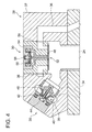
- FIG.3 and FIG.4 are schematic sectional views for explaining the configurations of the high-pressure valve 28 and the low-pressure valve 30.
- FIG.3 is a view showing a state when the high-pressure valve 28 is closed and the low-pressure valve 30 is open
- FIG.4 is a view showing a state when the high-pressure valve 28 is open and the low-pressure valve 30 is closed.
- the high-pressure valve 28, the low-pressure valves 30, and a casing 37 for the valves may be unitized into a valve unit 38 as illustrated in FIG.3 and FIG.4 .
- the high-pressure valve 28 illustrated in FIG.3 and FIG.4 is provided with a movable unit 40 including a valve element 35, a solenoid coil 42 which functions as an actuator for moving the movable unit 40 to a valve-opening position and a valve-closing position, a spring 44, and a valve seat 46.
- the high-pressure valve 28 is an electromagnetic poppet valve of normally closed type, and the valve seat 46 is provided on the working chamber 24 side with respect to the valve element 35.
- the high-pressure valve 28 is configured to switch the communication state between the working chamber 24 and the high-pressure line 12 (see FIG.2 ) by movement of the movable unit 40 resulting from electromagnetic force of the solenoid 42 or the energizing force of the spring 44.
- the movable unit 40 When the high-pressure valve 28 is not excited by the HPV control signal from the control unit 100, the movable unit 40 is energized by the spring 44 toward the valve seat 46, to be held in the position (the position of the movable unit 40 shown in FIG.3 ) where the working chamber 24 does not communicate with the high-pressure line 12.
- the movable unit 40 When the high-pressure valve 28 is excited by the HPV control signal from the control unit 100, the movable unit 40 is moved by the electromagnetic force against the energizing force of the spring 44 to the position (the position of the movable unit 40 shown in FIG.4 ) where the working chamber 24 communicates with the high-pressure line 12.
- the low-pressure valve 30 illustrated in FIG.3 and FIG.4 is provided with a movable unit 52 having a valve element 48 and an armature 50, a solenoid 54, a spring 56, and a valve seat 58.
- the low-pressure valve 30 is an electromagnetic poppet valve of normally open type, and the valve element 48 is provided on the working chamber 24 side with respect to the valve seat 58.
- the low-pressure valve 30 is configured to switch the communication state between the working chamber 24 and the low-pressure line 14 (see FIG.2 ) by movement of the movable unit 52 resulting from electromagnetic force of the solenoid 54 or the energizing force of the spring 56.
- the movable unit 52 When the low-pressure valve 30 is not excited by the LPV control signal from the control unit 100, the movable unit 52 is energized by the spring 56 in the direction of moving away from the valve seat 58 so as to be held in the valve-opening position (the position of the movable unit 52 in FIG.3 ) where the working chamber 24 communicates with the low-pressure line 14.
- the armature 50 is attracted by the electromagnetic force of the solenoid 54, and the movable unit 52 is moved by the electromagnetic force toward the valve seat 56 against the energizing force of the spring 56 to move to the valve-closing position (the position of the movable unit 52 in FIG.4 ) where the working chamber 24 does not communicate with the high-pressure line 12.
- the diagnostic system 70 for the hydraulic machine is, as illustrated in FIG.2(a) and (b) , provided with a pressure sensor 72 for detecting a pressure of the working chamber 24, and the an abnormality determination part 74 for determining abnormality of the hydraulic motor 10 based on the detection result of the pressure sensor 72.
- the abnormality determination part 74 may be included in the control/monitoring device 100 for controlling and monitoring the operation state of equipments constituting the hydraulic motor 10 (for example, the high-pressure valve 28 and the low-pressure valve 30) or measuring devices (for example, the pressure sensor 72).
- the pressure sensor 72 may be provided for each of the working chambers 24. In this case, it is possible to perform the abnormality determination for each of the cylinders 20 based on the pressure measured by the pressure sensor 72 and thus, it is possible to identify the cylinder 20 with abnormality.
- FIG.5 is a block diagram illustrating the configuration of the diagnostic system for the hydraulic machine.
- the diagnostic system 70 for the hydraulic machine is further provided with an integration part 76 and a dimensionless integral pressure obtaining part 78.
- the pressure measurement value of the working chamber 24 detected by the pressure sensor 72 is sent to the integration part 76.
- the pressure measurement value sent to the integration part 76 may not be the detection result directly obtained from the pressure sensor 72 and may be the value converted from the detection result of the pressure sensor into an appropriate pressure value by passing through a conversion part 91 and an offset addition part 92.
- a distortion value detected by the pressure sensor 72 may be converted into a suitable pressure value in the conversion part 91, and when offset calculation is required, an offset value may be added in the offset addition part 92.
- an integral value P is computed by integrating the pressure measurement value sent from the pressure sensor 72 in correspondence to a reciprocating motion cycle of the piston to calculate an integral value P.
- the integration corresponding to the reciprocating motion cycle of the piston 22 means finding the integral about time covering the period T of the reciprocating motion of the piston 22 (for example, from the time when the piston 22 reaches the bottom dead center to the time when the piston 22 reaches the bottom dead center after reaching the top dead center).
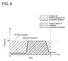
- a dimensionless integral pressure value P' ( P h ⁇ T) / P) is calculated.
- the dimensionless integral pressure value P' indicates a ratio of the integral value P calculated in the integration part 76 to the product of the pressure P h of the high-pressure line 12 and the reciprocating motion period (piston period) T of the piston 22.
- FIG.6 is a diagram visually showing "a ratio of the integral value P calculated in the integration part 76 to the product of the pressure P h of the high-pressure line 12 and the reciprocating motion period T of the piston 22" which is the dimensionless integral pressure value P'.
- abnormality determination can be performed in the abnormality determination part 74. Since the pressure of the high-pressure line 12 itself changes according to the operation state of the hydraulic machine, the integral value of the pressure (the cylinder pressure) inside the working chamber 24 communicating with the high-pressure line 12 via the high-pressure valve 28 is also affected by the operation state of the hydraulic machine. Therefore, by making it dimensionless by the pressure of the high-pressure line 12 as described above, it is possible to determine abnormality eliminating the influence of the operation state of the hydraulic machine (the hydraulic motor 10).
- the pressure P h of the high-pressure line 12 is obtained by processing the measurement value measured by a high-pressure line pressure measurement part 84 in a primary delay processing part 85 and an offset addition part 86 if needed.
- the piston period T is computed in a period calculation part 89 based on a value obtained by performing conversion processing of the measurement value measured by the rotation speed measurement part 87 of the hydraulic motor in a conversion part 88 if needed.
- the abnormality determination part 74 is configured to determine abnormality of the hydraulic motor 10 by at least considering whether or not the dimensionless integral pressure value P' is within a prescribed range. In the abnormality determination part 74, abnormality of the hydraulic motor 10 is determined, in addition to the dimensionless integral pressure value P', based on existence of the opening-closing command (the HPV control signal or LPV control signal) to the high-pressure valve 28 or the low-pressure valve 30 from the control unit 100.
- the opening-closing command the HPV control signal or LPV control signal
- the determination result of the abnormality determination part 74 may be outputted to a determination result output part 96 (for example, a monitor).
- a valve opening-closing command value I' explained below is used as information from the control unit 100, which indicates existence of the opening-closing command to the high-pressure valve 28 or the low-pressure valve 30.
- the valve opening-closing command value I' is obtained by processing suitable conversion etc. of a measurement value of the current passing through the solenoid (42, 54) of at least one of the high-pressure valve 28 or the low-pressure valve 30.
- the measurement value of the current is measured by a current measurement part 80. Since the current passing through the solenoid (42, 54) is generated due to the HPV control signal or the LPV control signal from the control unit 100, it shows whether or not there is the opening-closing command from the control unit 100.
- the measurement value (raw value) of the current flowing to the solenoid (42 54) acquired by the current measurement part 80 may be converted into a current value Iv by a conversion part 81, and may be a current value I by reproducing a pulse-like command value waveform about this current value I. Furthermore, the current value I may be processed in a primary delay processing part 83 by primary delay processing to obtain a valve opening-closing command value I' as an index which shows whether there is the opening-closing command from the control unit 100.
- whether the opening-closing command is provided for the high pressure valve 28 or the low-pressure valve 30 from the control unit may be determined from the HPV control signal or the LPV control signal outputted from the control unit.
- Iv0 ⁇ Iv11 and I0 ⁇ I11 indicate the current values in the solenoid (42, 54) of the high-pressure valve 28 or the low-pressure valve 30 corresponding to respective cylinders 20 or the low-pressure valve 30 in case where the hydraulic motor 10 has 12 cylinders 20.
- the abnormality determination part 74 includes a primary determination part 94 and a secondary determination part 95.
- the primary determination part 94 determines based on the above-mentioned dimensionless integral pressure value P' and the valve opening-closing command value I'.
- the secondary determination part 95 determines abnormality of the hydraulic machine based on the output P" from the primary determination part 94.
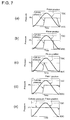
- (a) is a graph illustrating change of the cylinder pressure during a normal operation of the hydraulic motor
- (b) to (e) are graphs illustrating changes of the cylinder pressure corresponding to respective abnormal modes of the hydraulic motor.
- the cylinder pressure of the hydraulic motor 10 is substantially equal to the pressure of the low-pressure line 14 in a most part of the period (a compression stroke) while the piston 22 moves from the bottom dead center toward the top dead center.
- the solenoid 54 of the low-pressure valve 30 is excited to close the low-pressure valve 30, and immediately after that, the solenoid 42 of the high-pressure valve 28 is excited to open the high-pressure valve 28. Therefore, the cylinder pressure starts increasing rapidly from just before the top dead center and increases up to the pressure Ph of the high-pressure line 12.
- the piston 22 is moved downward from the top dead center to the bottom dead center by the pressure oil introduced to the working chamber 24 via the high pressure valve 28 (an intake stroke).
- the high-pressure valve 28 is changed into non-exciting state and closed.
- the low-pressure valve 30 is changed into non-exciting state and opened.
- the cylinder pressure drastically declines just before the bottom dead center and declines to the pressure of the low-pressure line 14.
- the period when the cylinder pressure is substantially equal to the pressure Ph of the high-pressure line 12 is approximately half of the reciprocating motion period T of the piston.
- the abnormality shown in FIG.7 (b) is the abnormality (early closing) which appears when the high-pressure valve 28 is closed ahead of the prescribed timing. Compared to the normal cylinder pressure change shown in FIG.7 (a) , the period when the cylinder pressure is substantially equal to the pressure Ph of the high pressure line 12 is slightly short.
- the abnormality shown in FIG.7(c) is the abnormality (latch fail) which appears when the low-pressure valve 30 is closed later than a prescribed timing and thus the high-pressure valve 28 is not opened at a prescribed timing.
- the period when the cylinder pressure is substantially equal to the pressure Ph of the high pressure line 12 is significantly short.
- the abnormality shown in FIG.7 (d) is the abnormality (intermittent juddering) which appears when, as a result of closing the high-pressure valve 28 later than a prescribed timing, the low-pressure valve 30 cannot open due to a fluid differential pressure acting on both sides of the valve element 48 of the low-pressure valve 30, although the low-pressure valve 30 is in the non-excited state and the piston 22 reaches the bottom dead center.
- the piston 22 starts moving up toward the top dead center from the bottom dead center after that, the operating fluid in the working chamber 24 is compressed in the state that the high-pressure valve 28 is opened and the low-pressure valve 30 stays closed. This makes it even harder to open the low-pressure valve 30.
- the period when the cylinder pressure is substantially equal to the pressure Ph of the high pressure line 12 is long in the case where the intermittent juddering occurs.
- the abnormality shown in FIG.7 (e) is the abnormality (continuous juddering) which appears when the high-pressure valve 28 stays open without being able to be closed for the entire cycle of the reciprocating motion of the piston 22 because the valve element 35 becomes immovable due to foreign matters being mixed in or fixation of the movable unit 40 of the high pressure valve 28.
- the period when the cylinder pressure is substantially equal to the pressure Ph of the high pressure line 12 is significantly long in the case where the continuous juddering occurs.
- FIG.8 is a flow chart illustrating one example of the abnormality determination process performed by the abnormality determination part 74.
- the abnormality determination process performed by the abnormality determination part 74 is explained in detail in reference to FIG.5 and FIG.8 .
- the primary determination part 94 determines whether or not the opening-closing command (motoring command) is provided for the high-pressure valve 28 and the low-pressure valve 30 based on the relation between the valve opening-closing command value I' and the threshold (see step S11 of FIG.8 ). If the valve opening-closing command value I' is greater than the threshold (40% in the example shown in FIG.8 ), the primary determination part 94 determines that the opening-closing command is provided for the high-pressure valve 28 and the low-pressure valve 30 (determined as YES in step S11 of FIG.8 ).
- the primary determination part 94 determines that the opening-closing command is not provided for the high-pressure valve 28 and the low-pressure valve 30 (determined as NO in step S11 of FIG.8 ).
- the determination process performed by the abnormality determination part 74 is as follows.
- the primary determination part 94 inputs a constant (for example, 50%) into the secondary determination part 95 as the output P", and the secondary determination part 95 determines that the hydraulic motor 10 is normal (see step S13 of FIG.8 ).
- the primary determination part 94 inputs the dimensionless integral pressure value P' into the secondary determination part 95 as the output P", and the secondary determination part 95 determines occurrence of abnormality (in step S14 of FIG.8 ).
- the abnormality determination part 74 is configured to determine, when the opening-closing command is not provided for the high-pressure valve 28 and the low-pressure valve 30 and the dimensionless integral pressure value P' exceeds the first threshold, occurrence of abnormality (continuous juddering) that the high-pressure valve 28 stays open without being able to be closed in the entire cycle of the reciprocating motion of the piston 22.
- the determination process performed by the abnormality determination part 74 is as follows.
- the primary determination part 94 inputs the dimensionless integral pressure value P' into the secondary determination part 95 as the output P" (in step S15 of FIG.8 ). Then, in the case where the output P" of the primary determination part 95 exceeds the first threshold (80% in the example shown in FIG.8 ) (when determined as YES in step S16), the secondary determination part 95 determines occurrence of continuous juddering (in step S17).
- the secondary determination part 95 is configured to determine, when the output P" of the primary determination part 95 exceeds an upper limit of a prescribed range (40% ⁇ P" ⁇ 60% in the example shown in FIG.8 ) (when determined as YES in step S18), occurrence of the abnormality (intermittent juddering) in which the high-pressure valve 28 is closed later than the prescribed timing. Furthermore, the secondary determination part 95 is configured to determine, when the output P" of the primary determination part 95 is within the prescribed range (40% ⁇ P" ⁇ 60% in the example shown in FIG.8 ) (when determined as YES in step S20), that the high-pressure valve 28 and the low-pressure valve 30 are normal.
- the secondary determination part 95 is configured to determine, when the output P" of the primary determination part 95 is below a lower limit of the prescribed range (40% ⁇ P" ⁇ 60% in the example shown in FIG.8 ) (when determined as NO in step S20), occurrence of the abnormality (early closing) where the high-pressure valve 28 is earlier than the prescribed timing or occurrence of the abnormality (latch fail) where the low-pressure valve 30 is closed later than the prescribed timing and thus the high-pressure valve 28 cannot be opened at the prescribed timing.
- the secondary determination part 95 determines occurrence of the early closing (in step S23), and in the case where the output P" of the primary determination part 95 is less than the threshold which is the lower limit of the prescribed range (10% in the example shown in FIG.8 ) (determined as NO in step S22), the secondary determination part 95 determines occurrence of the latch fail (in step S24).
- a variables output part 97 may be provided to output information relating to the pressure of the working chamber 24 detected by the pressure sensor 27 (the dimensionless integral pressure value P' in the example shown in FIG.5 ) to the control unit 100 of the hydraulic motor 10, and the information serves as variables for feedback control for at least one of the high-pressure valve 28 or the low-pressure valve 30.
- the control unit 100 may compute the opening-closing command (for example, opening-closing timing (the timing of excitation and non-excitation of the solenoid 42, 54)) to at least one of the high-pressure valve 28 or the low-pressure valve 30 by using a PI controller 98 so that the dimensionless integral pressure value P' (variables for feedback control) received from the variables output part 97 may approach a target value P*, and this opening-closing command may be outputted to a valve opening-closing command part 99.
- opening-closing command for example, opening-closing timing (the timing of excitation and non-excitation of the solenoid 42, 54)
- the diagnostic system 70 of the hydraulic machine further comprises a duty ratio calculation part configured to calculate a duty ratio which indicates a ratio of a period when the measurement value of the pressure of the working chamber 24 detected by the pressure sensor 72 is not less than the prescribed value to a period of the reciprocating motion of the piston 22.
- the abnormality determination part 74 is configured to determine abnormality of the hydraulic machine by at least considering whether or not the duty ratio calculated by the duty ratio calculation part is within a prescribed range.
- (a) to (e) are graphs each visually illustrating the duty ratio in a pressure waveform detected by the pressure sensor 72.
- the duty ratio ( ⁇ /T) is a ratio of the period ⁇ when the measurement value of the pressure of the working chamber 24 detected by the pressure sensor 72 is not less than the prescribed value to the period T of the reciprocating motion of the piston 22.
- a prescribed range may be may be defined using the ratio ⁇ a /T of the case shown in FIG.9(a) where the cylinder is in normal state. For example, when the difference between the duty ratio ⁇ /T calculated based on the measurement value of the pressure and the ratio ⁇ a /T is within 15% on the basis of ⁇ a /T, it is determined that the cylinder is in a normal state. When the difference exceeds 15%, it is determined that the cylinder is in an abnormal state. Further, FIG.9(b) to (e) show the duty ratios in the case of (b) early closing, (c) latch fail, (d) intermittent juddering and (e) continuous juddering, respectively.
- the abnormality determination part 74 is configured to compare, regarding at least one cycle of the reciprocating motion of the piston 22, an actual pressure waveform of the working chamber 24 detected by the pressure sensor 27 with an ideal normal pressure waveform which is predicted from an opening-closing command provided for at least one of the high-pressure valve 28 or the low-pressure valve 30 so as to determine abnormality of the hydraulic machine based on deviation of the actual pressure waveform from the ideal pressure waveform.
- FIG.10(a) is a graph schematically illustrating the valve opening-closing command
- FIG.10(b) to (d) show waveforms of the pressure of the working chamber (the cylinder pressure) detected by the pressure sensor 72 when the valve opening-closing command of FIG.10(a) is provided.
- FIG.10 (b) shows the ideal pressure waveform predicted from the valve opening-closing command of FIG.10(a).
- FIG.10(c) and (d) show pressure waveforms of the case where abnormality occurs.
- the waveform of the pressure (cylinder pressure) of the working chamber 24 detected by the pressure sensor 72 is, for instance, compared to the ideal pressure waveform in viewpoints such as the number of peaks in the pressure waveform per each cycle of the piston 22, the maximum pressure and the average pressure. If the pressure waveform having significant deviation from the ideal waveform as shown in FIG.10 (c) and (d) , it is determined that abnormality has occurred in the hydraulic machine.
- the abnormality determination part 74 is configured to determine abnormality of the high-pressure valve 28 and the low-pressure valve 30 based on a delay time TD of pressure change of the working chamber 24 caused by opening or closing of the at least one of the high-pressure valve 28 or the low-pressure valve 30 with respect to a timing of supplying the opening-closing control signal (HPV control signal or LPV control signal) to at least one of the high-pressure valve 28 or the low-pressure valve 30 from the control unit 100 of the hydraulic machine.
- FIG.11 is a chart showing a relationship between the cylinder pressure and the HPV control signal to the high-pressure valve 28 during the normal operation of the hydraulic machine.
- FIG.12 is a chart showing a relationship between the cylinder pressure and the HPV control signal to the high-pressure valve 28 during an abnormal operation of the hydraulic machine.
- the solenoid 42 of the high-pressure valve 28 is unexcited by the HPV control signal 132A, and then before the piston 22 reaches the bottom dead center, the high-pressure valve 28 is closed and immediately after this, the low-pressure valve 30 whose solenoid 53 is unexcited is now opened, whereby the cylinder pressure declines.
- the solenoid 42 of the high-pressure valve 28 is unexcited by the HPV control signal 132A at time t 1 , the high-pressure valve 28 cannot be closed before the piston 22 reaches the bottom dead center.
- the low-pressure valve 30 cannot open due to the fluid differential pressure acting on both sides of the valve element 48 of the low-pressure valve 30 and thus, the cylinder pressure remains high even at the bottom dead center of the piston 22.
- the delay time (ideal delay time TD 0 ) until the cylinder pressure actually falls from the transmitting time of a valve closing command (HPV control signal 132A) to the high-pressure valve 28 in the chart shown in FIG.11 the delay time (ideal delay time TD) until the cylinder pressure actually falls from the transmitting time of the valve closing command (HPV control signal 132A) to the high-pressure valve 28 in the chart shown in FIG.12 is significantly long.
- abnormality of the high-pressure valve 28 and the low-pressure valve 30 can be determined based on the deviation of the delay time TD from the ideal delay time TD 0 .
- the integration part 76, the dimensionless integral pressure obtaining part 78 and the abnormality determination part 74 are configured by FPGA (Field Programmable Gate Array) 90.
- the hydraulic motor 10 has twelve cylinders 20, the rotation shaft 32 rotates at 1000rpm, and the diagnostic system performs the abnormality determination of the hydraulic machine for each of the cylinders 20 every rotation of the rotation shaft 32.
- the abnormality determination needs to be performed 200 times per second. Therefore, by configuring the integration part 76, the dimensionless integral pressure obtaining part 78 and the abnormality determination part 74 by FPGA (Field Programmable Gate Array) 90 which is capable of high-speed parallel processing, the above-described abnormality determination of the hydraulic machine can be performed at high speed.
- FPGA Field Programmable Gate Array
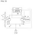
- FIG.13 is an illustration of the configuration of the hydraulic machine according to one embodiment.
- the hydraulic transmission 64 comprises: a rotation speed sensor 200 for detecting a rotation speed of the hydraulic motor 10; a first pressure sensor 210 provided at a first position in the low-pressure line 14 on the hydraulic motor 24 side to detect a pressure of the low-pressure line 14 at the first position; and a second pressure sensor 220 provided at a second position in the low-pressure line 14 on the hydraulic pump 8 side to detect a pressure of the low-pressure line 14 at the second position.
- the hydraulic transmission 64 further comprises a transmission diagnostic part 300 which is configured to diagnose abnormality of the hydraulic transmission 64 based on detection results of the rotation speed sensor 200, the first pressure sensor 210 and the second pressure sensor 220.
- the transmission diagnostic part 300 is configured to obtain a second estimated flow rate Q 2 in the low-pressure line 14 based on a pressure difference between the pressure in the low-pressure line 14 at the first position detected by the first pressure sensor 210 and the pressure in the low-pressure line 14 at the second position detected by the second pressure sensor 220, and a flow resistance in the low-pressure line 14 between the first position and the second position. For example, the flow resistance of the low-pressure line 14 between the first position and the second position is measured, and the expression of relation between the pressure difference between the first position and the second position and the flow rate of the operating fluid passing through the low-pressure line 14 is obtained beforehand. And the transmission diagnostic part 300 applies the difference between the pressure detected by the first pressure sensor 210 at the first position and the pressure detected by the second pressure sensor 220 at the second position to this relation expression obtained beforehand, so as to estimate the flow rate in the low pressure line 14.
- the transmission diagnostic part 300 determines abnormality of the hydraulic transmission 64.
- the first estimated flow rate Q 1 should be equal to the second estimated flow rate Q 2 .
- the measurement result of devices such as the rotation speed sensor 200 and the pressure sensors 210, 220
- the parameter required to compute the estimated flow rate such as a displacement ratio FD M defining the displacement volume of the hydraulic motor 10.
- failure can be estimated in one or some of the measuring devices or the devices that constitute the hydraulic motor 10. Therefore, it is possible to determine abnormality of the hydraulic transmission based on the difference between the first estimated flow rate Q 1 and the second estimated flow rate Q 2 .
Abstract
Description
- The present invention relates to a diagnostic system and a diagnostic method for a hydraulic machine, as well as a hydraulic transmission and a wind turbine generator.
- A hydraulic machine such as a hydraulic pump and a hydraulic motor has been known conventionally. For instance,
Patent Reference 1 describes a hydraulic machine for converting energy between fluid energy of operating fluid and rotational energy of a rotation shaft by using cyclical volume change of a working chamber which is formed by a cylinder and a piston. -
Patent Reference 2 describes, as a method for suppressing occurrence of opening and closing abnormality of a valve for switching a communication state between a working chamber of a hydraulic machine and outside the working chamber, control of an opening-closing timing of a valve in accordance with a condition of operating fluid (operating oil) and characteristics of components of a fluid operation machine. -
- [Patent Reference 1]
US 2010/0040470 - [Patent Reference 2]
WO 2011/104547 - In a hydraulic machine such as a hydraulic pump and a hydraulic motor, when the piston behavior becomes abnormal within the cylinder, for instance, due to the change in the opening and closing timing of the valve, it may cause problems such as performance decline of the hydraulic machine, occurrence of damage to the piston or cylinder due to seizing thereof caused by abnormal friction between the piston and the cylinder inner wall.
- To prevent these problems in advance, it is important to detect abnormality of the hydraulic machine before performance decline of the hydraulic machine or occurrence of damage to the piston or the like due to seizing.
- In this respect, there is almost no description in
Patent Reference - It is an object of at least one embodiment of the present invention to provide a diagnostic system and a diagnostic method for a hydraulic machine as well as a hydraulic transmission and a wind turbine generator, whereby abnormality of the hydraulic machine can be accurately diagnosed.
- A diagnostic system according to at least one embodiment of the present invention is for a hydraulic machine which comprises a rotation shaft, a cylinder, a piston forming a working chamber with the cylinder, a high-pressure valve and a low-pressure valve provided for the working chamber, and a converting mechanism for converting between rotational motion of the rotation shaft and reciprocating motion of the piston, and the diagnostic system comprises:
- a pressure sensor for detecting a pressure of the working chamber; and
- an abnormality determination part for determining abnormality of the hydraulic machine based on a detection result of the pressure sensor.
- A pressure inside the working chamber (hereinafter, also referred to as "cylinder pressure") changes in response to opening and closing of the high-pressure valve and the low-pressure valve as well as a reciprocation motion of the piston. During a normal operation of the hydraulic machine, the pressure in the working chamber changes periodically. Further, in the case where the cylinder pressure behaves differently from that of the normal operation of the hydraulic machine, such as the case where the cylinder pressure is high for a period longer or shorter than that of the normal operation, it is considered that abnormality has occurred in the hydraulic machine (e.g. abnormality of the high-pressure valve and the low-pressure valve, etc.).
- According to the diagnostic system of the hydraulic machine, the abnormality of the hydraulic machine is determined by the abnormality determination part based on the detection result of the pressure sensor and thus, it is possible to accurately diagnose abnormality of the hydraulic machine.
- In some embodiments, the diagnostic system for the hydraulic machine further comprises:
- an integration part for integrating measurement values of the pressure of the working chamber detected by the pressure sensor in correspondence to a reciprocating motion cycle of the piston to calculate an integral value; and
- a dimensionless integral pressure obtaining part for calculating a dimensionless integral pressure value which indicates a ratio of the integral value calculated by the integration part to a product of a period of the reciprocating motion of the piston and a pressure of a high-pressure line connected to the hydraulic machine for communication with the working chamber via the high-pressure valve, and
- the abnormality determination part is configured to determine abnormality of the hydraulic machine by at least considering whether or not the dimensionless integral is within a prescribed range.
- With this configuration, the abnormality determination part determines abnormality of the hydraulic machine by at least considering whether or not the dimensionless integral pressure value calculated by the dimensionless integral pressure obtaining part based on the pressure measurement value is within the prescribed range. Thus, it is possible to accurately diagnose abnormality of the hydraulic machine.
- As the pressure of the high-pressure oil line itself fluctuates depending on the operation state of the hydraulic machine, the integral value of the pressure (the cylinder pressure) inside the working chamber communication with the high-pressure line via the high-pressure valve is also affected by the operation state of the hydraulic machine. Therefore, by making it dimensionless by the pressure of the high-pressure line as described above, it is possible to determine abnormality eliminating influence of the operation state of the hydraulic machine.
- In some embodiments, in the case where a valve opening-closing command is not provided for the high-pressure valve and the low-pressure valve, the abnormality determination part is configured to determine, when the dimensionless integral pressure value exceeds a first threshold, occurrence of abnormality in which the high-pressure valve stays open without being able to be closed in the entire cycle of the reciprocating motion of the piston (hereinafter, referred to as "continuous juddering").
- With this configuration, occurrence of the continuous juddering can be detected by the simple technique based on existence of the opening-closing command to the high-pressure valve and the low-pressure valve and a size relation between the dimensionless integral pressure value and the first threshold value. Further, if the continuation juddering occurs, it may cause not only the performance decline of the hydraulic machine but damage to the piston by seizure, etc. Therefore, it is useful in the viewpoint of maintenance of the soundness of the hydraulic machine that occurrence of the continuation juddering is detectable with the above-mentioned configuration.
- In some embodiments, in the case where the valve opening-closing command is provided for at least one of the high-pressure valve or the low-pressure valve, the abnormality determination part is configured to:
- when the dimensionless integral pressure value is within the prescribed range, determine that the high-pressure valve and the low-pressure valve are normal;
- when the dimensionless integral pressure value exceeds an upper limit of the prescribed range, determine that the high-pressure valve is closed later than a prescribed timing (hereinafter referred to as "intermittent juddering"); and
- when the dimensionless integral pressure value is below a lower limit of the prescribed range, determine that the high-pressure valve is closed ahead of the prescribed timing (hereinafter referred to as "early closing") or that the low-pressure valve is closed later than a prescribed timing and thus the high-pressure valve is not opened at a prescribed timing (hereinafter referred to as "latch fail".
- With this configuration, occurrence of the intermittent juddering, the early closing or the latch fail can be detected by the simple technique based on existence of the opening-closing command to the high-pressure valve and the low-pressure valve and a size relation between the dimensionless integral pressure value and the first threshold value. Further, if the intermittent juddering, the early closing or the latch fail occurs, the performance of the hydraulic machine may decline. Therefore, it is useful in the viewpoint of maintaining the performance of the hydraulic machine that occurrence of these abnormalities is detectable with the above-mentioned configuration.
- In some embodiments, the integration part, the dimensionless integral pressure obtaining part and the abnormality determination part are configured by FPGA.
- In the hydraulic machine, for instance, in the case where the number of cylinders is large or where the rotation speed of the rotation shaft is high, it is necessary to perform high-speed processing in the operation in the integration part or the dimensionless integral pressure obtaining part, and the abnormality determination in the abnormality determination part, in order to perform the abnormality diagnosis of the hydraulic machine while delay is reduced.
- In this point, the FPGA (Field Programmable Gate Array), a high-speed parallel processing is possible. Therefore, with the above-mentioned configuration, since the integration part, the dimensionless integral pressure obtaining part and the abnormality determination part are configured by FPGA, the abnormality determination of the hydraulic machine can be performed at high speed.
- In some embodiments, the above diagnostic system for the hydraulic machine further comprises:
- a duty ratio calculation part configured to calculate a duty ratio which indicates a ratio of a period when the measurement value of the pressure of the working chamber detected by the pressure sensor is not less than a prescribed value to a period of the reciprocating motion of the piston, and
- the abnormality determination part is configured to determine abnormality of the hydraulic machine by at least considering whether or not the duty ratio calculated by the duty ratio calculation part is within a prescribed range.
- With this configuration, the abnormality determination part determines abnormality of the hydraulic machine based on whether or not the duty ratio calculated from the pressure detected by the pressure sensor is within the prescribed range. Therefore, it is possible to accurately diagnose abnormality of the hydraulic machine.
- In some embodiments, the abnormality determination part is configured to compare, regarding at least one cycle of the reciprocating motion of the piston, an actual pressure waveform of the working chamber detected by the pressure sensor with an ideal normal pressure waveform which is predicted from an opening-closing command provided for at least one of the high-pressure valve or the low-pressure valve so as to determine abnormality of the hydraulic machine based on deviation of the actual pressure waveform from the ideal pressure waveform.
- With this configuration, the abnormality determination part determines abnormality of the hydraulic machine based on the deviation of the actual waveform detected by the pressure sensor from the ideal pressure waveform predicted from the opening-closing command provided for at least one of the high-pressure valve or the low-pressure valve. Therefore, it is possible to accurately diagnose abnormality of the hydraulic machine.
- In some embodiments, the abnormality determination part is configured to compare, with respect to a timing of supplying an opening-closing signal to at least one of the high-pressure valve or the low-pressure valve from a control unit of the hydraulic machine, a delay time of pressure change of the working chamber caused by opening or closing of the at least one of the high-pressure valve or the low-pressure valve with an ideal delay time so as to determine abnormality of the high-pressure valve and the low-pressure valve based on a comparison result of comparing the delay time with the ideal delay time.
- The delay time of pressure change of the working chamber can be obtained from the timing of supplying the opening-closing signal to at least one of the high-pressure valve or the low-pressure valve from the control unit of the hydraulic machine and the measurement value of the pressure sensor. With this configuration, the abnormality determination part determines the abnormality of the hydraulic machine based on the comparison result of comparing the delay time based on the measurement value of the pressure sensor to the ideal delay time. Therefore, it is possible to accurately diagnose abnormality of the hydraulic machine.
- In some embodiments, the above diagnostic system for the hydraulic machine further comprises:
- a variables output part configured to output information relating to the pressure of the working chamber detected by the pressure sensor to a control unit of the hydraulic machine, the information serving as variables for feedback control for at least one of the high-pressure valve or the low-pressure valve.
- With this configuration, the information relating to the pressure of the working chamber (e.g. the dimensionless integral pressure value calculated by the dimensionless integral pressure obtaining part) is output to the control unit of the hydraulic machine as the variables for feedback control for at least one of the high-pressure valve or the low-pressure valve. Therefore, it is possible to achieve better operation of the hydraulic machine using this control unit.
- A hydraulic transmission according to at least one embodiment of the present invention comprises:
- a hydraulic pump configured to generate pressure oil;
- a hydraulic motor configured to be driven by the pressure oil from the hydraulic pump;
- a high-pressure line connecting a discharge port of the hydraulic pump and an intake port of the hydraulic motor;
- a low-pressure line connecting a discharge port of the hydraulic motor and an intake port of the hydraulic pump; and
- a hydraulic machine diagnostic part including any one of the diagnostic systems described above and configured to diagnose abnormality of at least one of the hydraulic pump or the hydraulic motor.
- The above hydraulic transmission comprises the hydraulic machine diagnostic part which includes the diagnostic system and is configured to diagnose abnormality of at least one of the hydraulic pump or the hydraulic motor. Thus, abnormality of at least one of the hydraulic pump or the hydraulic motor can be determined by the abnormality determination part based on the detection result of the pressure sensor provided in the diagnostic system. Therefore, it is possible to accurately diagnose abnormality of at least one of the hydraulic pump or the hydraulic motor.
- In some embodiments, the hydraulic transmission further comprises:
- a rotation speed sensor configured to detect a rotation speed of the hydraulic motor;
- a first pressure sensor provided at a first position in the low-pressure line on a hydraulic motor side to detect a pressure of the low-pressure line at the first position;
- a second pressure sensor provided at a second position in the low-pressure line on a hydraulic pump side to detect a pressure of the low-pressure line at the second position; and
- a transmission diagnostic part configured to diagnose abnormality of the hydraulic transmission based on detection results of the rotation speed sensor, the first pressure sensor and the second pressure sensor,
- the transmission diagnostic part is configured to:
- obtain a first estimated flow rate in the low-pressure line based on the rotation speed of the hydraulic motor detected by the rotation speed sensor and displacement of the hydraulic motor;
- obtain a second estimated flow rate in the low-pressure line based on a pressure difference between the pressure in the low-pressure line at the first position detected by the first pressure sensor and the pressure in the low-pressure line at the second position detected by the second pressure sensor, and a flow resistance in the low-pressure line between the first position and the second position; and
- determine abnormality of the hydraulic transmission based on a difference between the first estimated flow rate and the second estimated flow rate.
- With this configuration, the estimated flow rate in the low-pressure line is obtained in two methods. Specifically, the first estimated flow rate is obtained based on the detection result of the rotation speed sensor, and the second estimated flow rate is obtained based on the detection results of the first pressure sensor and the second pressure sensor. If the whole hydraulic transmission including various sensors (the rotation speed sensor, the first pressure sensor, the second pressure sensor, etc.) is functioning normally, the first estimated flow rate should be equal to the second estimated flow rate. On the other hand, if there is difference between the first estimated flow rate and the second estimated flow rate, it can be estimated that the measurement result of devices (such as the rotation speed sensor and the pressure sensor) used to estimate the flow rate or the parameter required to calculate the estimated flow rate (such as a displacement ratio FDM defining the displacement volume of the hydraulic motor) is different from the actual value. Specifically, failure can be estimated in either one of the measuring devices or the devices that constitute the hydraulic machine. Therefore, it is possible to determine abnormality of the hydraulic transmission based on the difference between the first estimated flow rate and the second estimated flow rate.
- A wind turbine generator according to at least one embodiment of the present invention comprises:
- any one of the hydraulic transmissions described above;
- a wind turbine rotor configured to input mechanical energy to the hydraulic pump of the hydraulic transmission; and
- a generator configured to be driven by the hydraulic motor of the hydraulic transmission.
- The hydraulic transmission included in the above-mentioned wind turbine generator comprises the hydraulic machine diagnostic part including the diagnostic system and configured to diagnose abnormality of at least one of the hydraulic pump or the hydraulic motor. Thus, abnormality of at least one of the hydraulic pump or the hydraulic motor can be determined by the abnormality determination part based on the detection result of the pressure sensor provided in the diagnostic system. Therefore, it is possible to accurately diagnose abnormality of at least one of the hydraulic pump or the hydraulic motor.
- A diagnostic method according to at least one embodiment of the present invention is for a hydraulic machine which comprises a rotation shaft, a cylinder, a piston forming a working chamber with the cylinder, a high-pressure valve and a low-pressure valve provided for the working chamber, and a converting mechanism for converting between rotational motion of the rotation shaft and reciprocating motion of the piston, and this diagnostic method comprises:
- a pressure detection step of detecting a pressure of the working chamber; and
- an abnormality determination step of determining abnormality of the hydraulic machine based on a detection result of the pressure detection step.
- According to the above diagnostic method for the hydraulic machine, abnormality of the hydraulic machine can be determined in the abnormality determination step based on the detection result of the pressure detection step. Therefore, it is possible to accurately diagnose abnormality of the hydraulic machine.
- In some embodiments, the diagnostic method for the hydraulic machine further comprises:
- an integration step for integrating measurement values of the pressure of the working chamber detected in the pressure detection step in correspondence to a reciprocating motion cycle of the piston so as to calculate an integral value; and
- a dimensionless integral pressure obtaining step for calculating a dimensionless integral pressure value which indicates a ratio of the integral value calculated in the integration step to a product of a period of the reciprocating motion of the piston and a pressure of a high-pressure line connected to the hydraulic machine for communication with the working chamber via the high-pressure valve, and
- in the abnormality determination step, abnormality of the hydraulic machine is determined by at least considering whether or not the dimensionless integral is within a prescribed range.
- According to the above diagnostic method for the hydraulic machine,
whether or not the dimensionless integral pressure value calculated in the dimensionless integral pressure obtaining step based on the pressure measurement value is within the prescribed range is at least considered in the abnormality determination step. Thus, it is possible to accurately diagnose abnormality of the hydraulic machine. - As the pressure of the high-pressure oil line itself fluctuates depending on the operation state of the hydraulic machine, the integral value of the pressure (the cylinder pressure) inside the working chamber communication with the high-pressure line via the high-pressure valve is also affected by the operation state of the hydraulic machine. Therefore, by making it dimensionless by the pressure of the high-pressure line as described above, it is possible to determine abnormality eliminating influence of the operation state of the hydraulic machine.
- According to at least one embodiment of the present invention, abnormality of the hydraulic machine can be diagnosed accurately in the hydraulic machine.
-
- [
FIG.1] FIG.1 is a schematic illustration of a configuration of a wind turbine generator according to one embodiment. - [
FIG.2] FIG.2 is a schematic illustration of a configuration of a diagnostic system for a hydraulic machine (a hydraulic motor) according to one embodiment. - [
FIG.3] FIG.3 is a schematic cross-sectional view explaining configurations of a high-pressure and a low-pressure valve. - [
FIG.4] FIG.4 is a schematic cross-sectional view explaining configurations of a high-pressure and a low-pressure valve. - [
FIG.5] FIG.5 is a block diagram illustrating a configuration of a diagnostic system for a hydraulic machine. - [
FIG.6] FIG.6 is a diagram visually showing a dimensionless integral pressure value P'. - [
FIG.7 ] (a) is a graph illustrating change of a cylinder pressure during a normal operation of a hydraulic motor, (b) to (e) are graphs illustrating changes of the cylinder pressure corresponding to respective abnormal modes of the hydraulic motor. - [
FIG.8] FIG.8 is a flow chart illustrating one example of an abnormality determination process performed by an abnormality determination part. - [
FIG.9 ] (a) to (e) are graphs each visually illustrating a duty ratio in a pressure waveform detected by a pressure sensor. - [
FIG.10 ] (a) is a graph schematically illustrating a valve opening-closing command, and (b) to (d) show waveforms of a pressure of a working chamber (a cylinder pressure) detected by the pressure sensor. - [
FIG.11] FIG.11 is a chart showing a relationship between the cylinder pressure and a HPV control signal to the high-pressure valve during the normal operation of the hydraulic machine. - [
FIG.12] FIG.12 is a chart showing a relationship between the cylinder pressure and a HPV control signal to the high-pressure valve during an abnormal operation of the hydraulic machine. - [
FIG.13] FIG.13 is an illustration of a configuration of a hydraulic machine according to one embodiment. - Embodiments of the present invention will now be described in detail with reference to the accompanying drawings. It is intended, however, that unless particularly specified, dimensions, materials, shape, its relative positions and the like shall be interpreted as illustrative only and not limitative of the scope of the present invention.
- In the following embodiments, a hydraulic machine according to one embodiment of the present invention is described using a hydraulic motor of a hydraulic transmission which constitutes a drive train of a wind turbine generator as one example. However, the hydraulic machine is not limited to this example and may be a hydraulic pump or a hydraulic motor which is applicable to arbitrary uses.
- First, a general structure of a wind turbine generator comprising a hydraulic machine (a hydraulic motor) which is an application target to which the diagnostic system and diagnostic method according to the present embodiment is applied.
-
FIG.1 is a schematic illustration of a configuration of a wind turbine generator according to one embodiment. As shown inFIG.1 , thewind turbine generator 1 is equipped with arotor 3 constituted by at least oneblade 2 and ahub 4. - In one embodiment, a
hydraulic pump 8 is connected to therotor 3 via arotation shaft 6. Ahydraulic motor 10 is connected to thehydraulic pump 8 through a high-pressure line 12 and a low-pressure line 14. Specifically, an outlet of thehydraulic pump 8 is connected to an inlet ofhydraulic motor 10 through the high-pressure line 12, and an inlet of thehydraulic pump 8 is connected to an outlet of thehydraulic motor 10 through the low-pressure line 14. Thehydraulic pump 8 is driven by therotation shaft 6 and boots a pressure of the operating oil to generate high-pressure operating oil (pressure oil). The pressure oil generated by thehydraulic pump 8 is supplied to thehydraulic motor 10 through the high-pressure line 12, and thehydraulic motor 10 is driven by this pressure oil.
The operating oil having performed work in thehydraulic motor 10 is returned to thehydraulic pump 8 through the low-pressure line 14 disposed between the outlet of thehydraulic motor 10 and the inlet of thehydraulic pump 8. - A
generator 16 is connected with thehydraulic motor 10. In one embodiment, thegenerator 16 is a synchronous generator connected to the grid and is configured to be driven by thehydraulic motor 10. - Further, a
nacelle 18 installed on thetower 19 covers at least a part of therotation shaft 6. In one embodiment, thehydraulic pump 8, thehydraulic motor 10 and thegenerator 16 are installed inside the nacelle18. - In the
wind turbine generator 1 shown inFIG.1 , rotation energy of therotor 3 is inputted into thegenerator 16 via ahydraulic transmission 64 including thehydraulic pump 8 and thehydraulic motor 10 to generate electric power in thegenerator 16. - Next, the diagnostic system and diagnostic method for the hydraulic machine according to the embodiment are explained.
FIG.2 is a schematic illustration of a configuration of a diagnostic system for a hydraulic machine (a hydraulic motor) according to one embodiment.FIG.2 (a) is a general illustration of the diagnostic system for the hydraulic machine, andFIG.2 (b) is an illustration of a configuration of a control/monitoring device. - A
diagnostic system 70 for the hydraulic machine illustrated inFIG.2 (a) is a diagnostic system for thehydraulic motor 10. Thehydraulic motor 10 comprises arotation shaft 32,cylinders 20,pistons 22 which form workingchambers 24 with thecylinders 20, a high-pressure valve 28 and a low-pressure valve 30 provided for the working chamber, and a convertingmechanism 25. - The converting
mechanism 25 is for converting between rotational motion of therotation shaft 32 and reciprocating motion of thepiston 22 and may include acam 26 having a cam profile engageable with thepiston 22. - From the perspective of smoothly convert reciprocating motion of the
piston 22 into rotational motion of therotation shaft 32, thepiston 22 is preferably constituted by apiston body 22A slidably moving in thecylinder 20, and a piston roller or a piston shoe which is attached to thepiston body 22A and contacts the cam profile of thecam 26. InFIG.2 , the example in which thepiston 22 is constituted by thepiston body 22A and apiston shoe 22B is illustrated. - The
cam 26 is an eccentric cam disposed eccentrically with respect to the axial center O of the rotation shaft (crankshaft) 32 of thehydraulic motor 10. While thepiston 22 moves up and down once, thecam 26 and therotation shaft 32 with thecam 26 attached thereto make one rotation. - In another embodiment, the
cam 26 is an annular multi-lobe cam (a ring cam) having two or more lobes (convex parts). In this case, while thecam 26 and therotation shaft 32 with thecam 26 attached thereto make one rotation, thepistons 22 reciprocate as many times as the number of lobes. - The high-
pressure valve 28 is provided in a high-pressure communication line 34 between the workingchamber 24 and the high-pressure lines 12 disposed outside the workingchamber 24, and is configured to switch a communication state between the workingchamber 24 and the high-pressure line 12. The low-pressure valve 30 is provided in a low-pressure communication line 36 between the workingchamber 24 and the low-pressure line14 disposed outside the workingchamber 24, and is configured to switch a communication state between the workingchamber 24 and the low-pressure line 14. - A control unit 100 (see
FIG.2 (b) ) contained in a control/monitoring device 110 is configured to control opening and closing operation of thehigh pressure valve 28 by supplying a HPV control signal to the high pressure valve 28 (an opening-closing command to the high pressure valve 28), and control opening and closing operation of the low-pressure valve 30 by supplying a LPV control signal to the low-pressure valve 30 (an opening-closing command to the low-pressure valve 30). - Moreover, the pressure of the working
chamber 24 detected by apressure sensor 72 is inputted to the control/monitoring device 110. The detection result of thispressure sensor 72 is used to determine abnormality of the hydraulic machine in aFPGA 90 which is described later. -
FIG.3 andFIG.4 are schematic sectional views for explaining the configurations of the high-pressure valve 28 and the low-pressure valve 30.FIG.3 is a view showing a state when the high-pressure valve 28 is closed and the low-pressure valve 30 is open, andFIG.4 is a view showing a state when the high-pressure valve 28 is open and the low-pressure valve 30 is closed. In some embodiments, the high-pressure valve 28, the low-pressure valves 30, and acasing 37 for the valves may be unitized into avalve unit 38 as illustrated inFIG.3 andFIG.4 . - The high-
pressure valve 28 illustrated inFIG.3 andFIG.4 is provided with amovable unit 40 including avalve element 35, asolenoid coil 42 which functions as an actuator for moving themovable unit 40 to a valve-opening position and a valve-closing position, aspring 44, and avalve seat 46. The high-pressure valve 28 is an electromagnetic poppet valve of normally closed type, and thevalve seat 46 is provided on the workingchamber 24 side with respect to thevalve element 35. The high-pressure valve 28 is configured to switch the communication state between the workingchamber 24 and the high-pressure line 12 (seeFIG.2 ) by movement of themovable unit 40 resulting from electromagnetic force of thesolenoid 42 or the energizing force of thespring 44. - When the high-
pressure valve 28 is not excited by the HPV control signal from thecontrol unit 100, themovable unit 40 is energized by thespring 44 toward thevalve seat 46, to be held in the position (the position of themovable unit 40 shown inFIG.3 ) where the workingchamber 24 does not communicate with the high-pressure line 12. When the high-pressure valve 28 is excited by the HPV control signal from thecontrol unit 100, themovable unit 40 is moved by the electromagnetic force against the energizing force of thespring 44 to the position (the position of themovable unit 40 shown inFIG.4 ) where the workingchamber 24 communicates with the high-pressure line 12. - The low-
pressure valve 30 illustrated inFIG.3 andFIG.4 is provided with amovable unit 52 having avalve element 48 and anarmature 50, asolenoid 54, aspring 56, and avalve seat 58. The low-pressure valve 30 is an electromagnetic poppet valve of normally open type, and thevalve element 48 is provided on the workingchamber 24 side with respect to thevalve seat 58. The low-pressure valve 30 is configured to switch the communication state between the workingchamber 24 and the low-pressure line 14 (seeFIG.2 ) by movement of themovable unit 52 resulting from electromagnetic force of thesolenoid 54 or the energizing force of thespring 56. - When the low-
pressure valve 30 is not excited by the LPV control signal from thecontrol unit 100, themovable unit 52 is energized by thespring 56 in the direction of moving away from thevalve seat 58 so as to be held in the valve-opening position (the position of themovable unit 52 inFIG.3 ) where the workingchamber 24 communicates with the low-pressure line 14. When the low-pressure valve 30 is excited by the LPV control signal from thecontrol unit 100, thearmature 50 is attracted by the electromagnetic force of thesolenoid 54, and themovable unit 52 is moved by the electromagnetic force toward thevalve seat 56 against the energizing force of thespring 56 to move to the valve-closing position (the position of themovable unit 52 inFIG.4 ) where the workingchamber 24 does not communicate with the high-pressure line 12. - The
diagnostic system 70 for the hydraulic machine is, as illustrated inFIG.2(a) and (b) , provided with apressure sensor 72 for detecting a pressure of the workingchamber 24, and the anabnormality determination part 74 for determining abnormality of thehydraulic motor 10 based on the detection result of thepressure sensor 72. Theabnormality determination part 74 may be included in the control/monitoring device 100 for controlling and monitoring the operation state of equipments constituting the hydraulic motor 10 (for example, the high-pressure valve 28 and the low-pressure valve 30) or measuring devices (for example, the pressure sensor 72). - In the case where the
hydraulic motor 10 has a plurality of workingchambers 20 formed by a plurality ofcylinders 20 and a plurality ofpistons 22, respectively, as shown inFIG.2 (a) , thepressure sensor 72 may be provided for each of the workingchambers 24. In this case, it is possible to perform the abnormality determination for each of thecylinders 20 based on the pressure measured by thepressure sensor 72 and thus, it is possible to identify thecylinder 20 with abnormality. -
FIG.5 is a block diagram illustrating the configuration of the diagnostic system for the hydraulic machine. - As shown in
FIG.5 , thediagnostic system 70 for the hydraulic machine is further provided with anintegration part 76 and a dimensionless integralpressure obtaining part 78. - The pressure measurement value of the working
chamber 24 detected by thepressure sensor 72 is sent to theintegration part 76. In this process, the pressure measurement value sent to theintegration part 76 may not be the detection result directly obtained from thepressure sensor 72 and may be the value converted from the detection result of the pressure sensor into an appropriate pressure value by passing through aconversion part 91 and an offsetaddition part 92. For example, a distortion value detected by thepressure sensor 72 may be converted into a suitable pressure value in theconversion part 91, and when offset calculation is required, an offset value may be added in the offsetaddition part 92. - In the
integration part 76, an integral value P is computed by integrating the pressure measurement value sent from thepressure sensor 72 in correspondence to a reciprocating motion cycle of the piston to calculate an integral value P. The integration corresponding to the reciprocating motion cycle of thepiston 22 means finding the integral about time covering the period T of the reciprocating motion of the piston 22 (for example, from the time when thepiston 22 reaches the bottom dead center to the time when thepiston 22 reaches the bottom dead center after reaching the top dead center). - In the dimensionless integral
pressure obtaining part 78, a dimensionless integral pressure value P' ( = ( Ph ×T) / P) is calculated. The dimensionless integral pressure value P' indicates a ratio of the integral value P calculated in theintegration part 76 to the product of the pressure Ph of the high-pressure line 12 and the reciprocating motion period (piston period) T of thepiston 22. Further,FIG.6 is a diagram visually showing "a ratio of the integral value P calculated in theintegration part 76 to the product of the pressure Ph of the high-pressure line 12 and the reciprocating motion period T of thepiston 22" which is the dimensionless integral pressure value P'. - Based on the dimensionless integral pressure value P' obtained in the above manner, abnormality determination can be performed in the
abnormality determination part 74. Since the pressure of the high-pressure line 12 itself changes according to the operation state of the hydraulic machine, the integral value of the pressure (the cylinder pressure) inside the workingchamber 24 communicating with the high-pressure line 12 via the high-pressure valve 28 is also affected by the operation state of the hydraulic machine. Therefore, by making it dimensionless by the pressure of the high-pressure line 12 as described above, it is possible to determine abnormality eliminating the influence of the operation state of the hydraulic machine (the hydraulic motor 10). - Further, the pressure Ph of the high-
pressure line 12 is obtained by processing the measurement value measured by a high-pressure linepressure measurement part 84 in a primarydelay processing part 85 and an offsetaddition part 86 if needed. Moreover, the piston period T is computed in aperiod calculation part 89 based on a value obtained by performing conversion processing of the measurement value measured by the rotationspeed measurement part 87 of the hydraulic motor in aconversion part 88 if needed. - The
abnormality determination part 74 is configured to determine abnormality of thehydraulic motor 10 by at least considering whether or not the dimensionless integral pressure value P' is within a prescribed range. In theabnormality determination part 74, abnormality of thehydraulic motor 10 is determined, in addition to the dimensionless integral pressure value P', based on existence of the opening-closing command (the HPV control signal or LPV control signal) to the high-pressure valve 28 or the low-pressure valve 30 from thecontrol unit 100. - As shown in
FIG.5 , the determination result of theabnormality determination part 74 may be outputted to a determination result output part 96 (for example, a monitor). - In some embodiments, as illustrated in
FIG.5 , a valve opening-closing command value I' explained below is used as information from thecontrol unit 100, which indicates existence of the opening-closing command to the high-pressure valve 28 or the low-pressure valve 30. - The valve opening-closing command value I' is obtained by processing suitable conversion etc. of a measurement value of the current passing through the solenoid (42, 54) of at least one of the high-
pressure valve 28 or the low-pressure valve 30. The measurement value of the current is measured by acurrent measurement part 80. Since the current passing through the solenoid (42, 54) is generated due to the HPV control signal or the LPV control signal from thecontrol unit 100, it shows whether or not there is the opening-closing command from thecontrol unit 100. The measurement value (raw value) of the current flowing to the solenoid (42 54) acquired by thecurrent measurement part 80 may be converted into a current value Iv by aconversion part 81, and may be a current value I by reproducing a pulse-like command value waveform about this current value I. Furthermore, the current value I may be processed in a primarydelay processing part 83 by primary delay processing to obtain a valve opening-closing command value I' as an index which shows whether there is the opening-closing command from thecontrol unit 100. - In another embodiment, whether the opening-closing command is provided for the
high pressure valve 28 or the low-pressure valve 30 from the control unit may be determined from the HPV control signal or the LPV control signal outputted from the control unit. - In
FIG.5 , Iv0 ∼ Iv11 and I0 ∼ I11 indicate the current values in the solenoid (42, 54) of the high-pressure valve 28 or the low-pressure valve 30 corresponding torespective cylinders 20 or the low-pressure valve 30 in case where thehydraulic motor 10 has 12cylinders 20. - The
abnormality determination part 74 includes aprimary determination part 94 and asecondary determination part 95. Theprimary determination part 94 determines based on the above-mentioned dimensionless integral pressure value P' and the valve opening-closing command value I'. Thesecondary determination part 95 determines abnormality of the hydraulic machine based on the output P" from theprimary determination part 94. - In
FIG.7, (a) is a graph illustrating change of the cylinder pressure during a normal operation of the hydraulic motor, (b) to (e) are graphs illustrating changes of the cylinder pressure corresponding to respective abnormal modes of the hydraulic motor. - As illustrated in
FIG.7A , the cylinder pressure of thehydraulic motor 10 is substantially equal to the pressure of the low-pressure line 14 in a most part of the period (a compression stroke) while thepiston 22 moves from the bottom dead center toward the top dead center. In thehydraulic motor 10, when thepiston 22 reaches just before the top dead center, thesolenoid 54 of the low-pressure valve 30 is excited to close the low-pressure valve 30, and immediately after that, thesolenoid 42 of the high-pressure valve 28 is excited to open the high-pressure valve 28. Therefore, the cylinder pressure starts increasing rapidly from just before the top dead center and increases up to the pressure Ph of the high-pressure line 12. Then, thepiston 22 is moved downward from the top dead center to the bottom dead center by the pressure oil introduced to the workingchamber 24 via the high pressure valve 28 (an intake stroke). When thepiston 22 is located just before the bottom dead center, the high-pressure valve 28 is changed into non-exciting state and closed. Immediately after this, the low-pressure valve 30 is changed into non-exciting state and opened. As a result, the cylinder pressure drastically declines just before the bottom dead center and declines to the pressure of the low-pressure line 14. Thus, the period when the cylinder pressure is substantially equal to the pressure Ph of the high-pressure line 12 is approximately half of the reciprocating motion period T of the piston. - On the other hand, if the opening-closing timing of the high-
pressure valve 28 and the low-pressure valve 30 shifts from the normal timing, abnormal cylinder pressure change appears as shown inFIG.7(b) - (e) . - The abnormality shown in
FIG.7 (b) is the abnormality (early closing) which appears when the high-pressure valve 28 is closed ahead of the prescribed timing. Compared to the normal cylinder pressure change shown inFIG.7 (a) , the period when the cylinder pressure is substantially equal to the pressure Ph of thehigh pressure line 12 is slightly short. - The abnormality shown in
FIG.7(c) is the abnormality (latch fail) which appears when the low-pressure valve 30 is closed later than a prescribed timing and thus the high-pressure valve 28 is not opened at a prescribed timing. Compared to the normal cylinder pressure change shown inFIG.7 (a) , the period when the cylinder pressure is substantially equal to the pressure Ph of thehigh pressure line 12 is significantly short. - The abnormality shown in
FIG.7 (d) is the abnormality (intermittent juddering) which appears when, as a result of closing the high-pressure valve 28 later than a prescribed timing, the low-pressure valve 30 cannot open due to a fluid differential pressure acting on both sides of thevalve element 48 of the low-pressure valve 30, although the low-pressure valve 30 is in the non-excited state and thepiston 22 reaches the bottom dead center. In this case, when thepiston 22 starts moving up toward the top dead center from the bottom dead center after that, the operating fluid in the workingchamber 24 is compressed in the state that the high-pressure valve 28 is opened and the low-pressure valve 30 stays closed. This makes it even harder to open the low-pressure valve 30. Compared to the normal cylinder pressure change shown inFIG.7 (a) , the period when the cylinder pressure is substantially equal to the pressure Ph of thehigh pressure line 12 is long in the case where the intermittent juddering occurs. - Further, the abnormality shown in
FIG.7 (e) is the abnormality (continuous juddering) which appears when the high-pressure valve 28 stays open without being able to be closed for the entire cycle of the reciprocating motion of thepiston 22 because thevalve element 35 becomes immovable due to foreign matters being mixed in or fixation of themovable unit 40 of thehigh pressure valve 28. Compared to the normal cylinder pressure change shown inFIG.7 (a) , the period when the cylinder pressure is substantially equal to the pressure Ph of thehigh pressure line 12 is significantly long in the case where the continuous juddering occurs. -
FIG.8 is a flow chart illustrating one example of the abnormality determination process performed by theabnormality determination part 74. The abnormality determination process performed by theabnormality determination part 74 is explained in detail in reference toFIG.5 andFIG.8 . - The
primary determination part 94 determines whether or not the opening-closing command (motoring command) is provided for the high-pressure valve 28 and the low-pressure valve 30 based on the relation between the valve opening-closing command value I' and the threshold (see step S11 ofFIG.8 ). If the valve opening-closing command value I' is greater than the threshold (40% in the example shown inFIG.8 ), theprimary determination part 94 determines that the opening-closing command is provided for the high-pressure valve 28 and the low-pressure valve 30 (determined as YES in step S11 ofFIG.8 ). On the other hand, if the valve opening-closing command value I' is not greater than the threshold (40% in the example shown inFIG.8 ), theprimary determination part 94 determines that the opening-closing command is not provided for the high-pressure valve 28 and the low-pressure valve 30 (determined as NO in step S11 ofFIG.8 ). - First, in the case where the valve opening-closing command value I' is not greater than the threshold (40% in the example shown in
FIG.8 ) and it is determined that the opening-closing command is not provided for the high-pressure valve 28 and the low-pressure valve 30 (determined as NO in step S11 ofFIG.8 ), the determination process performed by theabnormality determination part 74 is as follows. - When the valve opening-closing command value I' is not greater than the threshold (40% in the example shown in
FIG.8 ) and the dimensionless integral pressure value P' is not greater than the first threshold (60% in the example shown inFIG.8 ) (when determined as NO in step S12 ofFIG.8 ), theprimary determination part 94 inputs a constant (for example, 50%) into thesecondary determination part 95 as the output P", and thesecondary determination part 95 determines that thehydraulic motor 10 is normal (see step S13 ofFIG.8 ). - On the other hand, when the valve opening-closing command value I' is not greater than the threshold (40% in the example shown in
FIG.8 ) and the dimensionless integral pressure value P' is greater than the first threshold (60% in the example shown inFIG.8 ) (when determined as YES in step S12 ofFIG.8 ), theprimary determination part 94 inputs the dimensionless integral pressure value P' into thesecondary determination part 95 as the output P", and thesecondary determination part 95 determines occurrence of abnormality (in step S14 ofFIG.8 ). Specifically, theabnormality determination part 74 is configured to determine, when the opening-closing command is not provided for the high-pressure valve 28 and the low-pressure valve 30 and the dimensionless integral pressure value P' exceeds the first threshold, occurrence of abnormality (continuous juddering) that the high-pressure valve 28 stays open without being able to be closed in the entire cycle of the reciprocating motion of thepiston 22. - In contrast, in the case where the valve opening-closing command value I' is greater than the threshold (40% in the example shown in
FIG.8 ) and it is determined that the opening-closing command is provided for the high-pressure valve 28 and the low-pressure valve 30 (determined as YES in step S11 ofFIG.8 ), the determination process performed by theabnormality determination part 74 is as follows. - When the valve opening-closing command value I' is greater than the threshold (40% in the example shown in
FIG.8 ), theprimary determination part 94 inputs the dimensionless integral pressure value P' into thesecondary determination part 95 as the output P" (in step S15 ofFIG.8 ). Then, in the case where the output P" of theprimary determination part 95 exceeds the first threshold (80% in the example shown inFIG.8 ) (when determined as YES in step S16), thesecondary determination part 95 determines occurrence of continuous juddering (in step S17). Further, thesecondary determination part 95 is configured to determine, when the output P" of theprimary determination part 95 exceeds an upper limit of a prescribed range (40% < P" < 60% in the example shown inFIG.8 ) (when determined as YES in step S18), occurrence of the abnormality (intermittent juddering) in which the high-pressure valve 28 is closed later than the prescribed timing. Furthermore, thesecondary determination part 95 is configured to determine, when the output P" of theprimary determination part 95 is within the prescribed range (40% < P" < 60% in the example shown inFIG.8 ) (when determined as YES in step S20), that the high-pressure valve 28 and the low-pressure valve 30 are normal. Moreover, thesecondary determination part 95 is configured to determine, when the output P" of theprimary determination part 95 is below a lower limit of the prescribed range (40% < P" < 60% in the example shown inFIG.8 ) (when determined as NO in step S20), occurrence of the abnormality (early closing) where the high-pressure valve 28 is earlier than the prescribed timing or occurrence of the abnormality (latch fail) where the low-pressure valve 30 is closed later than the prescribed timing and thus the high-pressure valve 28 cannot be opened at the prescribed timing. In some embodiments, in the case where the output P" of theprimary determination part 95 is greater than a threshold which is below the lower limit of the prescribed range (10% in the example shown inFIG.8 ) (determined as YES in step S22), thesecondary determination part 95 determines occurrence of the early closing (in step S23), and in the case where the output P" of theprimary determination part 95 is less than the threshold which is the lower limit of the prescribed range (10% in the example shown inFIG.8 ) (determined as NO in step S22), thesecondary determination part 95 determines occurrence of the latch fail (in step S24). - In addition, as shown in
FIG.5 , in some embodiments, avariables output part 97 may be provided to output information relating to the pressure of the workingchamber 24 detected by the pressure sensor 27 (the dimensionless integral pressure value P' in the example shown inFIG.5 ) to thecontrol unit 100 of thehydraulic motor 10, and the information serves as variables for feedback control for at least one of the high-pressure valve 28 or the low-pressure valve 30. Thecontrol unit 100 may compute the opening-closing command (for example, opening-closing timing (the timing of excitation and non-excitation of thesolenoid 42, 54)) to at least one of the high-pressure valve 28 or the low-pressure valve 30 by using aPI controller 98 so that the dimensionless integral pressure value P' (variables for feedback control) received from thevariables output part 97 may approach a target value P*, and this opening-closing command may be outputted to a valve opening-closing command part 99. - In some embodiments, the
diagnostic system 70 of the hydraulic machine further comprises a duty ratio calculation part configured to calculate a duty ratio which indicates a ratio of a period when the measurement value of the pressure of the workingchamber 24 detected by thepressure sensor 72 is not less than the prescribed value to a period of the reciprocating motion of thepiston 22. Theabnormality determination part 74 is configured to determine abnormality of the hydraulic machine by at least considering whether or not the duty ratio calculated by the duty ratio calculation part is within a prescribed range. - In
FIG.9, (a) to (e) are graphs each visually illustrating the duty ratio in a pressure waveform detected by thepressure sensor 72. InFIG.9(a) to (e) , the duty ratio (τ/T) is a ratio of the period τ when the measurement value of the pressure of the workingchamber 24 detected by thepressure sensor 72 is not less than the prescribed value to the period T of the reciprocating motion of thepiston 22. - A prescribed range may be may be defined using the ratio τa/T of the case shown in
FIG.9(a) where the cylinder is in normal state. For example, when the difference between the duty ratio τ/T calculated based on the measurement value of the pressure and the ratio τa/T is within 15% on the basis of τa/T, it is determined that the cylinder is in a normal state. When the difference exceeds 15%, it is determined that the cylinder is in an abnormal state. Further,FIG.9(b) to (e) show the duty ratios in the case of (b) early closing, (c) latch fail, (d) intermittent juddering and (e) continuous juddering, respectively. - In some embodiments, the
abnormality determination part 74 is configured to compare, regarding at least one cycle of the reciprocating motion of thepiston 22, an actual pressure waveform of the workingchamber 24 detected by the pressure sensor 27 with an ideal normal pressure waveform which is predicted from an opening-closing command provided for at least one of the high-pressure valve 28 or the low-pressure valve 30 so as to determine abnormality of the hydraulic machine based on deviation of the actual pressure waveform from the ideal pressure waveform. -
FIG.10(a) is a graph schematically illustrating the valve opening-closing command, andFIG.10(b) to (d) show waveforms of the pressure of the working chamber (the cylinder pressure) detected by thepressure sensor 72 when the valve opening-closing command ofFIG.10(a) is provided.FIG.10 (b) shows the ideal pressure waveform predicted from the valve opening-closing command ofFIG.10(a). FIG.10(c) and (d) show pressure waveforms of the case where abnormality occurs. - The waveform of the pressure (cylinder pressure) of the working
chamber 24 detected by thepressure sensor 72 is, for instance, compared to the ideal pressure waveform in viewpoints such as the number of peaks in the pressure waveform per each cycle of thepiston 22, the maximum pressure and the average pressure. If the pressure waveform having significant deviation from the ideal waveform as shown inFIG.10 (c) and (d) , it is determined that abnormality has occurred in the hydraulic machine. - In some embodiments, the
abnormality determination part 74 is configured to determine abnormality of the high-pressure valve 28 and the low-pressure valve 30 based on a delay time TD of pressure change of the workingchamber 24 caused by opening or closing of the at least one of the high-pressure valve 28 or the low-pressure valve 30 with respect to a timing of supplying the opening-closing control signal (HPV control signal or LPV control signal) to at least one of the high-pressure valve 28 or the low-pressure valve 30 from thecontrol unit 100 of the hydraulic machine. -
FIG.11 is a chart showing a relationship between the cylinder pressure and the HPV control signal to the high-pressure valve 28 during the normal operation of the hydraulic machine.FIG.12 is a chart showing a relationship between the cylinder pressure and the HPV control signal to the high-pressure valve 28 during an abnormal operation of the hydraulic machine. - As illustrated in
FIG.11 , at time t1, thesolenoid 42 of the high-pressure valve 28 is unexcited by theHPV control signal 132A, and then before thepiston 22 reaches the bottom dead center, the high-pressure valve 28 is closed and immediately after this, the low-pressure valve 30 whose solenoid 53 is unexcited is now opened, whereby the cylinder pressure declines. In contrast, in the example shown inFIG.12 , although thesolenoid 42 of the high-pressure valve 28 is unexcited by theHPV control signal 132A at time t1, the high-pressure valve 28 cannot be closed before thepiston 22 reaches the bottom dead center. As a result, in spite of being in the non-excitation state, the low-pressure valve 30 cannot open due to the fluid differential pressure acting on both sides of thevalve element 48 of the low-pressure valve 30 and thus, the cylinder pressure remains high even at the bottom dead center of thepiston 22. - Therefore, compared to the delay time (ideal delay time TD0) until the cylinder pressure actually falls from the transmitting time of a valve closing command (
HPV control signal 132A) to the high-pressure valve 28 in the chart shown inFIG.11 , the delay time (ideal delay time TD) until the cylinder pressure actually falls from the transmitting time of the valve closing command (HPV control signal 132A) to the high-pressure valve 28 in the chart shown inFIG.12 is significantly long. Thus, by comparing the delay time TD and the ideal delay time TD0 of the pressure change of the workingchamber 24 from the transmitting time of the opening-closing control signal (HPV control signal or LPV control signal) from thecontrol unit 100, abnormality of the high-pressure valve 28 and the low-pressure valve 30 can be determined based on the deviation of the delay time TD from the ideal delay time TD0. - In the
diagnostic system 70 of the hydraulic machine illustrated inFIG.5 , theintegration part 76, the dimensionless integralpressure obtaining part 78 and theabnormality determination part 74 are configured by FPGA (Field Programmable Gate Array) 90. - For instance, the
hydraulic motor 10 has twelvecylinders 20, therotation shaft 32 rotates at 1000rpm, and the diagnostic system performs the abnormality determination of the hydraulic machine for each of thecylinders 20 every rotation of therotation shaft 32. In this case, the abnormality determination needs to be performed 200 times per second. Therefore, by configuring theintegration part 76, the dimensionless integralpressure obtaining part 78 and theabnormality determination part 74 by FPGA (Field Programmable Gate Array) 90 which is capable of high-speed parallel processing, the above-described abnormality determination of the hydraulic machine can be performed at high speed. -
FIG.13 is an illustration of the configuration of the hydraulic machine according to one embodiment. - In some embodiments, the
hydraulic transmission 64 comprises: arotation speed sensor 200 for detecting a rotation speed of thehydraulic motor 10; afirst pressure sensor 210 provided at a first position in the low-pressure line 14 on thehydraulic motor 24 side to detect a pressure of the low-pressure line 14 at the first position; and asecond pressure sensor 220 provided at a second position in the low-pressure line 14 on thehydraulic pump 8 side to detect a pressure of the low-pressure line 14 at the second position. - The
hydraulic transmission 64 further comprises a transmissiondiagnostic part 300 which is configured to diagnose abnormality of thehydraulic transmission 64 based on detection results of therotation speed sensor 200, thefirst pressure sensor 210 and thesecond pressure sensor 220. - The transmission
diagnostic part 300 is configured to obtain a first estimated flow rate Q1 in the low-pressure line 14 based on the rotation speed of thehydraulic motor 10 detected by therotation speed sensor 200 and displacement of thehydraulic motor 10. More specifically, the transmissiondiagnostic part 300 computes the first estimated flow rate Q1 using the formula, Q1 = nM × FDM × VgM × NM, wherein nM is the total number of the pistons of thehydraulic motor 10, FDM is a ratio of the current displacement to the maximum displacement of the hydraulic motor 10 (a ratio of the number of active working chambers to the total number of the cylinders), VgM is a piston displacement volume per cylinder, NM is the rotation speed of thehydraulic motor 10. - Further, the transmission
diagnostic part 300 is configured to obtain a second estimated flow rate Q2 in the low-pressure line 14 based on a pressure difference between the pressure in the low-pressure line 14 at the first position detected by thefirst pressure sensor 210 and the pressure in the low-pressure line 14 at the second position detected by thesecond pressure sensor 220, and a flow resistance in the low-pressure line 14 between the first position and the second position. For example, the flow resistance of the low-pressure line 14 between the first position and the second position is measured, and the expression of relation between the pressure difference between the first position and the second position and the flow rate of the operating fluid passing through the low-pressure line 14 is obtained beforehand. And the transmissiondiagnostic part 300 applies the difference between the pressure detected by thefirst pressure sensor 210 at the first position and the pressure detected by thesecond pressure sensor 220 at the second position to this relation expression obtained beforehand, so as to estimate the flow rate in thelow pressure line 14. - Based on the difference between the first estimated flow rate Q1 and the second estimated flow rate Q2 obtained in the above manner, the transmission
diagnostic part 300 determines abnormality of thehydraulic transmission 64. - If the whole
hydraulic transmission 64 including various sensors (therotation speed sensor 200, thefirst pressure sensor 210, thesecond pressure sensor 220, etc.) is functioning normally, the first estimated flow rate Q1 should be equal to the second estimated flow rate Q2. On the other hand, if there is difference between the first estimated flow rate Q1 and the second estimated flow rate Q2, it can be estimated that the measurement result of devices (such as therotation speed sensor 200 and thepressure sensors 210, 220) used to estimate the flow rate or the parameter required to compute the estimated flow rate (such as a displacement ratio FDM defining the displacement volume of the hydraulic motor 10) is different from the actual value. Specifically, failure can be estimated in one or some of the measuring devices or the devices that constitute thehydraulic motor 10. Therefore, it is possible to determine abnormality of the hydraulic transmission based on the difference between the first estimated flow rate Q1 and the second estimated flow rate Q2. -
- 1
- Wind turbine generator
- 2
- Blade
- 3
- Rotor
- 4
- Hub
- 6
- Rotation shaft
- 8
- Hydraulic pump
- 10
- Hydraulic motor
- 12
- High-pressure line
- 14
- Low-pressure line
- 16
- Generator
- 18
- Nacelle
- 19
- Tower
- 20
- Cylinder
- 22
- Piston
- 24
- Working chamber
- 25
- Converting mechanism
- 26
- Cam
- 28
- High-pressure valve
- 30
- Low-pressure valve
- 32
- Rotation shaft (Hydraulic motor)
- 34
- High-pressure communication line
- 35
- Valve element
- 36
- Low-pressure communication line
- 40
- Movable unit
- 42
- Solenoid coil
- 44
- Spring
- 46
- Valve seat
- 48
- Valve element
- 50
- Armature
- 52
- Movable unit
- 54
- Solenoid
- 56
- Spring
- 58
- Valve seat
- 64
- Hydraulic transmission
- 70
- Diagnostic system
- 72
- Pressure sensor
- 74
- Abnormality determination part
- 90
- FPGA
- 100
- Control unit
- 110
- Control/monitoring device
- 200
- Rotation speed sensor
- 210
- First pressure sensor
- 220
- Second pressure sensor
- 300
- Transmission diagnostic part
Claims (14)
- A diagnostic system for a hydraulic machine which comprises a rotation shaft (32), a cylinder (20), a piston (22) forming a working chamber (24) with the cylinder, a high-pressure valve (28) and a low-pressure valve (30) provided for the working chamber, and a converting mechanism (25) for converting between rotational motion of the rotation shaft (32) and reciprocating motion of the piston (22), the diagnostic system comprising:a pressure sensor (72) for detecting a pressure of the working chamber (24); andan abnormality determination part (74) for determining abnormality of the hydraulic machine based on a detection result of the pressure sensor (72).
- The diagnostic system for the hydraulic machine according to claim 1, further comprising:an integration part (76) for integrating measurement values of the pressure of the working chamber detected by the pressure sensor (72) in correspondence to a reciprocating motion cycle of the piston (22) to calculate an integral value; anda dimensionless integral pressure obtaining part (78) for calculating a dimensionless integral pressure value (P') which indicates a ratio of the integral value calculated by the integration part to a product of a period of the reciprocating motion of the piston and a pressure of a high-pressure line (12) connected to the hydraulic machine for communication with the working chamber via the high-pressure valve (28),wherein the abnormality determination part (74) is configured to determine abnormality of the hydraulic machine by at least considering whether or not the dimensionless integral pressure value (P') is within a prescribed range.
- The diagnostic system for the hydraulic machine according to claim 2,
wherein, in the case where a valve opening-closing command is not provided for the high-pressure valve (28) and the low-pressure valve (30), the abnormality determination part (74) is configured to determine, when the dimensionless integral pressure value (P') exceeds a first threshold, occurrence of abnormality in which the high-pressure valve (28) stays open without being able to be closed in the entire cycle of the reciprocating motion of the piston (22). - The diagnostic system for the hydraulic machine according to claim 3,
wherein, in the case where the valve opening-closing command is provided for at least one of the high-pressure valve (28) or the low-pressure valve (30), the abnormality determination part (74) is configured to:when the dimensionless integral pressure value (P') is within the prescribed range, determine that the high-pressure valve (28) and the low-pressure valve (30) are normal;when the dimensionless integral pressure value (P') exceeds an upper limit of the prescribed range, determine that the high-pressure valve (28) is closed later than a prescribed timing; andwhen the dimensionless integral pressure value (P') is below a lower limit of the prescribed range, determine that the high-pressure valve (28) is closed ahead of the prescribed timing or that the low-pressure valve (30) is closed later than a prescribed timing and thus the high-pressure valve (28) is not opened at a prescribed timing. - The diagnostic system for the hydraulic machine according to any one of claims 2 to 4,
wherein the integration part (76), the dimensionless integral pressure obtaining part (78) and the abnormality determination part (74) are configured by FPGA. - The diagnostic system for the hydraulic machine according to claim 1, further comprising:a duty ratio calculation part configured to calculate a duty ratio which indicates a ratio of a period when the measurement value of the pressure of the working chamber (24) detected by the pressure sensor (72) is not less than a prescribed value to a period of the reciprocating motion of the piston (22),wherein the abnormality determination part (74) is configured to determine abnormality of the hydraulic machine by at least considering whether or not the duty ratio calculated by the duty ratio calculation part is within a prescribed range.
- The diagnostic system for the hydraulic machine according to claim 1,
wherein the abnormality determination part (74) is configured to compare, regarding at least one cycle of the reciprocating motion of the piston (22), an actual pressure waveform of the working chamber (24) detected by the pressure sensor (72) with an ideal normal pressure waveform which is predicted from an opening-closing command provided for at least one of the high-pressure valve (28) or the low-pressure valve (30) so as to determine abnormality of the hydraulic machine based on deviation of the actual pressure waveform from the ideal pressure waveform. - The diagnostic system for the hydraulic machine according to claim 1,
wherein the abnormality determination part (74) is configured to compare, with respect to a timing of supplying an opening-closing signal to at least one of the high-pressure valve (28) or the low-pressure valve (30) from a control unit of the hydraulic machine, a delay time of pressure change of the working chamber (24) caused by opening or closing of the at least one of the high-pressure valve (28) or the low-pressure valve (30) with an ideal delay time so as to determine abnormality of the high-pressure valve and the low-pressure valve based on a comparison result of comparing the delay time with the ideal delay time. - The diagnostic system for the hydraulic machine according to any one of claims 1 to 8, further comprising:a variables output part (97) configured to output information relating to the pressure of the working chamber (24) detected by the pressure sensor (72) to a control unit (100) of the hydraulic machine, the information serving as variables for feedback control for at least one of the high-pressure valve (28) or the low-pressure valve (30).
- A hydraulic transmission comprising:a hydraulic pump (8) configured to generate pressure oil;a hydraulic motor (10) configured to be driven by the pressure oil from the hydraulic pump;a high-pressure line (12) connecting a discharge port of the hydraulic pump and an intake port of the hydraulic motor;a low-pressure line (14) connecting a discharge port of the hydraulic motor and an intake port of the hydraulic pump; anda hydraulic machine diagnostic part including the diagnostic system described in any one of claims 1 to 9 and configured to diagnose abnormality of at least one of the hydraulic pump (8) or the hydraulic motor (10).
- The hydraulic transmission according to claim 10, further comprising:a rotation speed sensor (200) configured to detect a rotation speed of the hydraulic motor (10);a first pressure sensor (210) provided at a first position in the low-pressure line (14) on a hydraulic motor side to detect a pressure of the low-pressure line (14) at the first position;a second pressure sensor (220) provided at a second position in the low-pressure line (14) on a hydraulic pump side to detect a pressure of the low-pressure line (14) at the second position; anda transmission diagnostic part (300) configured to diagnose abnormality of the hydraulic transmission based on detection results of the rotation speed sensor (200), the first pressure sensor (210) and the second pressure sensor (220),wherein the transmission diagnostic part (300) is configured to:obtain a first estimated flow rate in the low-pressure line (14) based on the rotation speed of the hydraulic motor (10) detected by the rotation speed sensor (200) and displacement of the hydraulic motor;obtain a second estimated flow rate in the low-pressure line (14) based on a pressure difference between the pressure in the low-pressure line at the first position detected by the first pressure sensor (210) and the pressure in the low-pressure line at the second position detected by the second pressure sensor (220), and a flow resistance in the low-pressure line (14) between the first position and the second position; anddetermine abnormality of the hydraulic transmission (64) based on a difference between the first estimated flow rate and the second estimated flow rate.
- A wind turbine generator comprising:the hydraulic transmission (64) described in claim 10 or 11;a wind turbine rotor (3) configured to input mechanical energy to the hydraulic pump (8) of the hydraulic transmission; anda generator (16) configured to be driven by the hydraulic motor (10) of the hydraulic transmission (64).
- A diagnostic method for a hydraulic machine which comprises a rotation shaft (32), a cylinder (20), a piston (22) forming a working chamber (24) with the cylinder, a high-pressure valve (28) and a low-pressure valve (30) provided for the working chamber, and a converting mechanism (25) for converting between rotational motion of the rotation shaft and reciprocating motion of the piston (22), the diagnostic method comprising:a pressure detection step for detecting a pressure of the working chamber (24); andan abnormality determination step of determining abnormality of the hydraulic machine based on a detection result of the pressure detection step.
- The diagnostic method for the hydraulic machine according to claim 13, further comprising:an integration step for integrating measurement values of the pressure of the working chamber (24) detected in the pressure detection step in correspondence to a reciprocating motion cycle of the piston (22) so as to calculate an integral value; anda dimensionless integral pressure obtaining step for calculating a dimensionless integral pressure value (P') which indicates a ratio of the integral value calculated in the integration step to a product of a period of the reciprocating motion of the piston (22) and a pressure of a high-pressure line (12) connected to the hydraulic machine for communication with the working chamber (24) via the high-pressure valve (28),wherein, in the abnormality determination step, abnormality of the hydraulic machine is determined by at least considering whether or not the dimensionless integral pressure value (P') is within a prescribed range.
Applications Claiming Priority (1)
| Application Number | Priority Date | Filing Date | Title |
|---|---|---|---|
| JP2013270844A JP5931844B2 (en) | 2013-12-27 | 2013-12-27 | Diagnosis system and diagnosis method for hydraulic machine, hydraulic transmission and wind power generator |
Publications (2)
| Publication Number | Publication Date |
|---|---|
| EP2889480A1 true EP2889480A1 (en) | 2015-07-01 |
| EP2889480B1 EP2889480B1 (en) | 2017-07-05 |
Family
ID=50729384
Family Applications (1)
| Application Number | Title | Priority Date | Filing Date |
|---|---|---|---|
| EP14168555.2A Active EP2889480B1 (en) | 2013-12-27 | 2014-05-16 | Diagnostic system and diagnostic method for hydraulic machine, and hydraulic transmission and wind turbine generator |
Country Status (2)
| Country | Link |
|---|---|
| EP (1) | EP2889480B1 (en) |
| JP (1) | JP5931844B2 (en) |
Cited By (6)
| Publication number | Priority date | Publication date | Assignee | Title |
|---|---|---|---|---|
| EP3211276A1 (en) * | 2016-02-26 | 2017-08-30 | Mitsubishi Heavy Industries, Ltd. | System and method for diagnosing hydraulic machine, hydraulic machine, and renewable-energy type power generating apparatus |
| EP3211232A1 (en) * | 2016-02-26 | 2017-08-30 | Mitsubishi Heavy Industries, Ltd. | System and method for diagnosing hydraulic machine, hydraulic machine, hydraulic transmission, and renewable-energy type power generating apparatus |
| EP3211395B1 (en) * | 2016-02-26 | 2019-04-10 | Mitsubishi Heavy Industries, Ltd. | Method and system for diagnosing hydraulic machine, hydraulic machine, and renewable-energy type power generating apparatus |
| US11174843B2 (en) | 2017-09-22 | 2021-11-16 | Mitsubishi Power, Ltd. | Solar thermal power generation equipment including wind turbine on the same vertically oriented shaft |
| CN116906477A (en) * | 2023-07-17 | 2023-10-20 | 大庆石油管理局有限公司 | Hydraulic transmission system device used in tower type pumping unit hand brake |
| CN117006178A (en) * | 2023-08-04 | 2023-11-07 | 大庆石油管理局有限公司 | Flexible braking device of tower crane |
Families Citing this family (4)
| Publication number | Priority date | Publication date | Assignee | Title |
|---|---|---|---|---|
| JP6736987B2 (en) * | 2016-06-03 | 2020-08-05 | 日本精工株式会社 | Condition monitoring device for rotating parts of wind power generator |
| JP6234524B1 (en) * | 2016-08-26 | 2017-11-22 | 三菱重工業株式会社 | Hydraulic motor operation method, operation control system, hydraulic transmission and renewable energy power generator |
| CN110792565B (en) * | 2019-10-17 | 2020-12-25 | 中广核(北京)新能源科技有限公司 | Main shaft-free direct-drive generator for wind power generation |
| CN113123956B (en) * | 2021-04-07 | 2023-02-28 | 郑州恩普特科技股份有限公司 | Water hammer fault diagnosis method for water pump |
Citations (10)
| Publication number | Priority date | Publication date | Assignee | Title |
|---|---|---|---|---|
| EP0183295A1 (en) * | 1984-11-15 | 1986-06-04 | Dowell Schlumberger Corp. | A method of observing the pumping characteristics of a positive displacement pump, and a pump enabling the method to be implemented |
| US5846056A (en) * | 1995-04-07 | 1998-12-08 | Dhindsa; Jasbir S. | Reciprocating pump system and method for operating same |
| WO2006124746A2 (en) * | 2005-05-16 | 2006-11-23 | Miller Davis J | System and method for power pump performance monitoring and analysis |
| WO2008066589A2 (en) * | 2006-11-30 | 2008-06-05 | Entegris, Inc. | System and method for operation of a pump |
| US20080190176A1 (en) * | 2005-04-14 | 2008-08-14 | Klaus Muller | Method and Device For Monitoring a Fluid Flow Delivered By Means of a Pump |
| US20090252620A1 (en) * | 2007-07-30 | 2009-10-08 | Lazzara Gerard S | Reinforced smart mud pump |
| US20100040470A1 (en) | 2008-08-13 | 2010-02-18 | Jacob Johannes Nies | Wind energy system with fluid-working machine with non-symmetric actuation |
| GB2482879A (en) * | 2010-08-17 | 2012-02-22 | Artemis Intelligent Power Ltd | Fluid-working machine with asymmetrically profiled multi-lobe ring cam |
| US20120076670A1 (en) * | 2010-02-23 | 2012-03-29 | Artemis Intelligent Power Limited | Fluid-working machine and method of operating a fluid-working machine |
| US20120156056A1 (en) * | 2010-12-17 | 2012-06-21 | Aisan Kogyo Kabushiki Kaisha | Pump units |
Family Cites Families (8)
| Publication number | Priority date | Publication date | Assignee | Title |
|---|---|---|---|---|
| JPS62135674A (en) * | 1985-12-09 | 1987-06-18 | Hitachi Constr Mach Co Ltd | Hydraulic pump and motor device |
| JPH11280637A (en) * | 1998-03-31 | 1999-10-15 | Kayaba Ind Co Ltd | Generator |
| JP2007107458A (en) * | 2005-10-13 | 2007-04-26 | Honda Motor Co Ltd | Control device of internal combustion engine |
| JP4851978B2 (en) * | 2007-03-29 | 2012-01-11 | 新潟原動機株式会社 | Combustion control method and apparatus for gas engine |
| JP5583204B2 (en) * | 2010-11-30 | 2014-09-03 | 三菱重工業株式会社 | Energy extraction device and method of operating energy extraction device |
| JP5502189B2 (en) * | 2010-11-30 | 2014-05-28 | 三菱重工業株式会社 | Renewable energy power generator and method of operating the same |
| JP5524409B2 (en) * | 2011-05-30 | 2014-06-18 | 三菱重工業株式会社 | Renewable energy power generator and method of operating the same |
| JP6055608B2 (en) * | 2012-04-26 | 2016-12-27 | 日立オートモティブシステムズ株式会社 | Engine control device |
-
2013
- 2013-12-27 JP JP2013270844A patent/JP5931844B2/en active Active
-
2014
- 2014-05-16 EP EP14168555.2A patent/EP2889480B1/en active Active
Patent Citations (10)
| Publication number | Priority date | Publication date | Assignee | Title |
|---|---|---|---|---|
| EP0183295A1 (en) * | 1984-11-15 | 1986-06-04 | Dowell Schlumberger Corp. | A method of observing the pumping characteristics of a positive displacement pump, and a pump enabling the method to be implemented |
| US5846056A (en) * | 1995-04-07 | 1998-12-08 | Dhindsa; Jasbir S. | Reciprocating pump system and method for operating same |
| US20080190176A1 (en) * | 2005-04-14 | 2008-08-14 | Klaus Muller | Method and Device For Monitoring a Fluid Flow Delivered By Means of a Pump |
| WO2006124746A2 (en) * | 2005-05-16 | 2006-11-23 | Miller Davis J | System and method for power pump performance monitoring and analysis |
| WO2008066589A2 (en) * | 2006-11-30 | 2008-06-05 | Entegris, Inc. | System and method for operation of a pump |
| US20090252620A1 (en) * | 2007-07-30 | 2009-10-08 | Lazzara Gerard S | Reinforced smart mud pump |
| US20100040470A1 (en) | 2008-08-13 | 2010-02-18 | Jacob Johannes Nies | Wind energy system with fluid-working machine with non-symmetric actuation |
| US20120076670A1 (en) * | 2010-02-23 | 2012-03-29 | Artemis Intelligent Power Limited | Fluid-working machine and method of operating a fluid-working machine |
| GB2482879A (en) * | 2010-08-17 | 2012-02-22 | Artemis Intelligent Power Ltd | Fluid-working machine with asymmetrically profiled multi-lobe ring cam |
| US20120156056A1 (en) * | 2010-12-17 | 2012-06-21 | Aisan Kogyo Kabushiki Kaisha | Pump units |
Cited By (8)
| Publication number | Priority date | Publication date | Assignee | Title |
|---|---|---|---|---|
| EP3211276A1 (en) * | 2016-02-26 | 2017-08-30 | Mitsubishi Heavy Industries, Ltd. | System and method for diagnosing hydraulic machine, hydraulic machine, and renewable-energy type power generating apparatus |
| EP3211232A1 (en) * | 2016-02-26 | 2017-08-30 | Mitsubishi Heavy Industries, Ltd. | System and method for diagnosing hydraulic machine, hydraulic machine, hydraulic transmission, and renewable-energy type power generating apparatus |
| EP3211395B1 (en) * | 2016-02-26 | 2019-04-10 | Mitsubishi Heavy Industries, Ltd. | Method and system for diagnosing hydraulic machine, hydraulic machine, and renewable-energy type power generating apparatus |
| US11174843B2 (en) | 2017-09-22 | 2021-11-16 | Mitsubishi Power, Ltd. | Solar thermal power generation equipment including wind turbine on the same vertically oriented shaft |
| CN116906477A (en) * | 2023-07-17 | 2023-10-20 | 大庆石油管理局有限公司 | Hydraulic transmission system device used in tower type pumping unit hand brake |
| CN116906477B (en) * | 2023-07-17 | 2024-01-30 | 大庆石油管理局有限公司 | Hydraulic transmission system device used in tower type pumping unit hand brake |
| CN117006178A (en) * | 2023-08-04 | 2023-11-07 | 大庆石油管理局有限公司 | Flexible braking device of tower crane |
| CN117006178B (en) * | 2023-08-04 | 2024-03-01 | 大庆石油管理局有限公司 | Flexible braking device of tower crane |
Also Published As
| Publication number | Publication date |
|---|---|
| JP5931844B2 (en) | 2016-06-08 |
| EP2889480B1 (en) | 2017-07-05 |
| JP2015124848A (en) | 2015-07-06 |
Similar Documents
| Publication | Publication Date | Title |
|---|---|---|
| EP2889480B1 (en) | Diagnostic system and diagnostic method for hydraulic machine, and hydraulic transmission and wind turbine generator | |
| EP3104005B1 (en) | Diagnosis system for a hydraulic machine, a hydraulic machine, a wind turbine power generating apparatus, and a method of diagnosing hydraulic machine | |
| CN100564902C (en) | The method of hydraulic driving system and operation hydraulic driving system | |
| JP2015124848A5 (en) | ||
| EP2896830B1 (en) | Hydraulic machine and power generating apparatus | |
| EP3121444B1 (en) | Fluid working machine and method of operating a fluid working machine | |
| KR101717042B1 (en) | An valve actuator using air compression | |
| EP3211276B1 (en) | Hydraulic machine with diagnosis system, renewable-energy type power generating apparatus and method for diagnosing hydraulic machine | |
| EP3211275B1 (en) | Method and system for diagnosing hydraulic machine, hydraulic machine, and renewable-energy type power generating apparatus | |
| EP3211395B1 (en) | Method and system for diagnosing hydraulic machine, hydraulic machine, and renewable-energy type power generating apparatus | |
| EP3211232B1 (en) | System and method for diagnosing hydraulic machine, hydraulic machine, hydraulic transmission, and renewable-energy type power generating apparatus | |
| JP6449102B2 (en) | Diagnosis method and apparatus for hydraulic machine, renewable energy type power generation apparatus and diagnosis method therefor | |
| EP2871371A1 (en) | Switching unit, hydraulic machine and power generating apparatus | |
| EP4317684A1 (en) | Method of controlling a valve | |
| EP2873870B1 (en) | Spool valve assembly, hydraulic machine and power generating apparatus | |
| US20200166036A1 (en) | Method and device for expanding a gas with a reciprocating-piston machine | |
| KR102169666B1 (en) | Method for testing quick closing of actuator for power plant | |
| EP3287636B1 (en) | Operation method and operation control system for hydraulic motor, hydraulic transmission, and renewable-energy type power generating apparatus | |
| JP2018155220A (en) | Hydraulic machine and foreign matter detection method for the same |
Legal Events
| Date | Code | Title | Description |
|---|---|---|---|
| PUAI | Public reference made under article 153(3) epc to a published international application that has entered the european phase |
Free format text: ORIGINAL CODE: 0009012 |
|
| 17P | Request for examination filed |
Effective date: 20140516 |
|
| AK | Designated contracting states |
Kind code of ref document: A1 Designated state(s): AL AT BE BG CH CY CZ DE DK EE ES FI FR GB GR HR HU IE IS IT LI LT LU LV MC MK MT NL NO PL PT RO RS SE SI SK SM TR |
|
| AX | Request for extension of the european patent |
Extension state: BA ME |
|
| R17P | Request for examination filed (corrected) |
Effective date: 20151120 |
|
| RBV | Designated contracting states (corrected) |
Designated state(s): AL AT BE BG CH CY CZ DE DK EE ES FI FR GB GR HR HU IE IS IT LI LT LU LV MC MK MT NL NO PL PT RO RS SE SI SK SM TR |
|
| 17Q | First examination report despatched |
Effective date: 20160429 |
|
| GRAP | Despatch of communication of intention to grant a patent |
Free format text: ORIGINAL CODE: EPIDOSNIGR1 |
|
| RIC1 | Information provided on ipc code assigned before grant |
Ipc: F03C 1/40 20060101ALI20161014BHEP Ipc: F04B 49/06 20060101ALI20161014BHEP Ipc: F03C 1/053 20060101ALI20161014BHEP Ipc: F04B 17/02 20060101AFI20161014BHEP Ipc: F04B 7/00 20060101ALI20161014BHEP |
|
| INTG | Intention to grant announced |
Effective date: 20161102 |
|
| GRAJ | Information related to disapproval of communication of intention to grant by the applicant or resumption of examination proceedings by the epo deleted |
Free format text: ORIGINAL CODE: EPIDOSDIGR1 |
|
| GRAS | Grant fee paid |
Free format text: ORIGINAL CODE: EPIDOSNIGR3 |
|
| GRAP | Despatch of communication of intention to grant a patent |
Free format text: ORIGINAL CODE: EPIDOSNIGR1 |
|
| INTC | Intention to grant announced (deleted) | ||
| INTG | Intention to grant announced |
Effective date: 20170222 |
|
| GRAA | (expected) grant |
Free format text: ORIGINAL CODE: 0009210 |
|
| AK | Designated contracting states |
Kind code of ref document: B1 Designated state(s): AL AT BE BG CH CY CZ DE DK EE ES FI FR GB GR HR HU IE IS IT LI LT LU LV MC MK MT NL NO PL PT RO RS SE SI SK SM TR |
|
| REG | Reference to a national code |
Ref country code: GB Ref legal event code: FG4D |
|
| REG | Reference to a national code |
Ref country code: CH Ref legal event code: EP |
|
| REG | Reference to a national code |
Ref country code: AT Ref legal event code: REF Ref document number: 906803 Country of ref document: AT Kind code of ref document: T Effective date: 20170715 |
|
| REG | Reference to a national code |
Ref country code: IE Ref legal event code: FG4D |
|
| REG | Reference to a national code |
Ref country code: DE Ref legal event code: R096 Ref document number: 602014011414 Country of ref document: DE |
|
| REG | Reference to a national code |
Ref country code: NL Ref legal event code: MP Effective date: 20170705 |
|
| REG | Reference to a national code |
Ref country code: AT Ref legal event code: MK05 Ref document number: 906803 Country of ref document: AT Kind code of ref document: T Effective date: 20170705 |
|
| REG | Reference to a national code |
Ref country code: LT Ref legal event code: MG4D |
|
| PG25 | Lapsed in a contracting state [announced via postgrant information from national office to epo] |
Ref country code: HR Free format text: LAPSE BECAUSE OF FAILURE TO SUBMIT A TRANSLATION OF THE DESCRIPTION OR TO PAY THE FEE WITHIN THE PRESCRIBED TIME-LIMIT Effective date: 20170705 Ref country code: NO Free format text: LAPSE BECAUSE OF FAILURE TO SUBMIT A TRANSLATION OF THE DESCRIPTION OR TO PAY THE FEE WITHIN THE PRESCRIBED TIME-LIMIT Effective date: 20171005 Ref country code: LT Free format text: LAPSE BECAUSE OF FAILURE TO SUBMIT A TRANSLATION OF THE DESCRIPTION OR TO PAY THE FEE WITHIN THE PRESCRIBED TIME-LIMIT Effective date: 20170705 Ref country code: AT Free format text: LAPSE BECAUSE OF FAILURE TO SUBMIT A TRANSLATION OF THE DESCRIPTION OR TO PAY THE FEE WITHIN THE PRESCRIBED TIME-LIMIT Effective date: 20170705 Ref country code: FI Free format text: LAPSE BECAUSE OF FAILURE TO SUBMIT A TRANSLATION OF THE DESCRIPTION OR TO PAY THE FEE WITHIN THE PRESCRIBED TIME-LIMIT Effective date: 20170705 Ref country code: NL Free format text: LAPSE BECAUSE OF FAILURE TO SUBMIT A TRANSLATION OF THE DESCRIPTION OR TO PAY THE FEE WITHIN THE PRESCRIBED TIME-LIMIT Effective date: 20170705 Ref country code: SE Free format text: LAPSE BECAUSE OF FAILURE TO SUBMIT A TRANSLATION OF THE DESCRIPTION OR TO PAY THE FEE WITHIN THE PRESCRIBED TIME-LIMIT Effective date: 20170705 |
|
| PG25 | Lapsed in a contracting state [announced via postgrant information from national office to epo] |
Ref country code: LV Free format text: LAPSE BECAUSE OF FAILURE TO SUBMIT A TRANSLATION OF THE DESCRIPTION OR TO PAY THE FEE WITHIN THE PRESCRIBED TIME-LIMIT Effective date: 20170705 Ref country code: ES Free format text: LAPSE BECAUSE OF FAILURE TO SUBMIT A TRANSLATION OF THE DESCRIPTION OR TO PAY THE FEE WITHIN THE PRESCRIBED TIME-LIMIT Effective date: 20170705 Ref country code: GR Free format text: LAPSE BECAUSE OF FAILURE TO SUBMIT A TRANSLATION OF THE DESCRIPTION OR TO PAY THE FEE WITHIN THE PRESCRIBED TIME-LIMIT Effective date: 20171006 Ref country code: PL Free format text: LAPSE BECAUSE OF FAILURE TO SUBMIT A TRANSLATION OF THE DESCRIPTION OR TO PAY THE FEE WITHIN THE PRESCRIBED TIME-LIMIT Effective date: 20170705 Ref country code: RS Free format text: LAPSE BECAUSE OF FAILURE TO SUBMIT A TRANSLATION OF THE DESCRIPTION OR TO PAY THE FEE WITHIN THE PRESCRIBED TIME-LIMIT Effective date: 20170705 Ref country code: BG Free format text: LAPSE BECAUSE OF FAILURE TO SUBMIT A TRANSLATION OF THE DESCRIPTION OR TO PAY THE FEE WITHIN THE PRESCRIBED TIME-LIMIT Effective date: 20171005 Ref country code: IS Free format text: LAPSE BECAUSE OF FAILURE TO SUBMIT A TRANSLATION OF THE DESCRIPTION OR TO PAY THE FEE WITHIN THE PRESCRIBED TIME-LIMIT Effective date: 20171105 |
|
| REG | Reference to a national code |
Ref country code: DE Ref legal event code: R097 Ref document number: 602014011414 Country of ref document: DE |
|
| PG25 | Lapsed in a contracting state [announced via postgrant information from national office to epo] |
Ref country code: RO Free format text: LAPSE BECAUSE OF FAILURE TO SUBMIT A TRANSLATION OF THE DESCRIPTION OR TO PAY THE FEE WITHIN THE PRESCRIBED TIME-LIMIT Effective date: 20170705 Ref country code: DK Free format text: LAPSE BECAUSE OF FAILURE TO SUBMIT A TRANSLATION OF THE DESCRIPTION OR TO PAY THE FEE WITHIN THE PRESCRIBED TIME-LIMIT Effective date: 20170705 Ref country code: CZ Free format text: LAPSE BECAUSE OF FAILURE TO SUBMIT A TRANSLATION OF THE DESCRIPTION OR TO PAY THE FEE WITHIN THE PRESCRIBED TIME-LIMIT Effective date: 20170705 |
|
| PLBE | No opposition filed within time limit |
Free format text: ORIGINAL CODE: 0009261 |
|
| STAA | Information on the status of an ep patent application or granted ep patent |
Free format text: STATUS: NO OPPOSITION FILED WITHIN TIME LIMIT |
|
| REG | Reference to a national code |
Ref country code: FR Ref legal event code: PLFP Year of fee payment: 5 |
|
| PG25 | Lapsed in a contracting state [announced via postgrant information from national office to epo] |
Ref country code: IT Free format text: LAPSE BECAUSE OF FAILURE TO SUBMIT A TRANSLATION OF THE DESCRIPTION OR TO PAY THE FEE WITHIN THE PRESCRIBED TIME-LIMIT Effective date: 20170705 Ref country code: SM Free format text: LAPSE BECAUSE OF FAILURE TO SUBMIT A TRANSLATION OF THE DESCRIPTION OR TO PAY THE FEE WITHIN THE PRESCRIBED TIME-LIMIT Effective date: 20170705 Ref country code: EE Free format text: LAPSE BECAUSE OF FAILURE TO SUBMIT A TRANSLATION OF THE DESCRIPTION OR TO PAY THE FEE WITHIN THE PRESCRIBED TIME-LIMIT Effective date: 20170705 Ref country code: SK Free format text: LAPSE BECAUSE OF FAILURE TO SUBMIT A TRANSLATION OF THE DESCRIPTION OR TO PAY THE FEE WITHIN THE PRESCRIBED TIME-LIMIT Effective date: 20170705 |
|
| 26N | No opposition filed |
Effective date: 20180406 |
|
| PG25 | Lapsed in a contracting state [announced via postgrant information from national office to epo] |
Ref country code: SI Free format text: LAPSE BECAUSE OF FAILURE TO SUBMIT A TRANSLATION OF THE DESCRIPTION OR TO PAY THE FEE WITHIN THE PRESCRIBED TIME-LIMIT Effective date: 20170705 |
|
| REG | Reference to a national code |
Ref country code: CH Ref legal event code: PL |
|
| REG | Reference to a national code |
Ref country code: BE Ref legal event code: MM Effective date: 20180531 |
|
| PG25 | Lapsed in a contracting state [announced via postgrant information from national office to epo] |
Ref country code: MC Free format text: LAPSE BECAUSE OF FAILURE TO SUBMIT A TRANSLATION OF THE DESCRIPTION OR TO PAY THE FEE WITHIN THE PRESCRIBED TIME-LIMIT Effective date: 20170705 |
|
| REG | Reference to a national code |
Ref country code: IE Ref legal event code: MM4A |
|
| PG25 | Lapsed in a contracting state [announced via postgrant information from national office to epo] |
Ref country code: LI Free format text: LAPSE BECAUSE OF NON-PAYMENT OF DUE FEES Effective date: 20180531 Ref country code: CH Free format text: LAPSE BECAUSE OF NON-PAYMENT OF DUE FEES Effective date: 20180531 |
|
| PG25 | Lapsed in a contracting state [announced via postgrant information from national office to epo] |
Ref country code: LU Free format text: LAPSE BECAUSE OF NON-PAYMENT OF DUE FEES Effective date: 20180516 |
|
| PG25 | Lapsed in a contracting state [announced via postgrant information from national office to epo] |
Ref country code: IE Free format text: LAPSE BECAUSE OF NON-PAYMENT OF DUE FEES Effective date: 20180516 |
|
| PG25 | Lapsed in a contracting state [announced via postgrant information from national office to epo] |
Ref country code: BE Free format text: LAPSE BECAUSE OF NON-PAYMENT OF DUE FEES Effective date: 20180531 |
|
| PG25 | Lapsed in a contracting state [announced via postgrant information from national office to epo] |
Ref country code: MT Free format text: LAPSE BECAUSE OF NON-PAYMENT OF DUE FEES Effective date: 20180516 |
|
| PG25 | Lapsed in a contracting state [announced via postgrant information from national office to epo] |
Ref country code: TR Free format text: LAPSE BECAUSE OF FAILURE TO SUBMIT A TRANSLATION OF THE DESCRIPTION OR TO PAY THE FEE WITHIN THE PRESCRIBED TIME-LIMIT Effective date: 20170705 |
|
| PG25 | Lapsed in a contracting state [announced via postgrant information from national office to epo] |
Ref country code: PT Free format text: LAPSE BECAUSE OF FAILURE TO SUBMIT A TRANSLATION OF THE DESCRIPTION OR TO PAY THE FEE WITHIN THE PRESCRIBED TIME-LIMIT Effective date: 20170705 |
|
| PG25 | Lapsed in a contracting state [announced via postgrant information from national office to epo] |
Ref country code: HU Free format text: LAPSE BECAUSE OF FAILURE TO SUBMIT A TRANSLATION OF THE DESCRIPTION OR TO PAY THE FEE WITHIN THE PRESCRIBED TIME-LIMIT; INVALID AB INITIO Effective date: 20140516 Ref country code: CY Free format text: LAPSE BECAUSE OF FAILURE TO SUBMIT A TRANSLATION OF THE DESCRIPTION OR TO PAY THE FEE WITHIN THE PRESCRIBED TIME-LIMIT Effective date: 20170705 Ref country code: MK Free format text: LAPSE BECAUSE OF NON-PAYMENT OF DUE FEES Effective date: 20170705 |
|
| PG25 | Lapsed in a contracting state [announced via postgrant information from national office to epo] |
Ref country code: AL Free format text: LAPSE BECAUSE OF FAILURE TO SUBMIT A TRANSLATION OF THE DESCRIPTION OR TO PAY THE FEE WITHIN THE PRESCRIBED TIME-LIMIT Effective date: 20170705 |
|
| REG | Reference to a national code |
Ref country code: DE Ref legal event code: R082 Ref document number: 602014011414 Country of ref document: DE Representative=s name: CBDL PATENTANWAELTE GBR, DE |
|
| REG | Reference to a national code |
Ref country code: FR Ref legal event code: PLFP Year of fee payment: 10 |
|
| PGFP | Annual fee paid to national office [announced via postgrant information from national office to epo] |
Ref country code: GB Payment date: 20230330 Year of fee payment: 10 |
|
| PGFP | Annual fee paid to national office [announced via postgrant information from national office to epo] |
Ref country code: FR Payment date: 20230411 Year of fee payment: 10 Ref country code: DE Payment date: 20230331 Year of fee payment: 10 |