EP2889461A1 - NOx reducing device - Google Patents
NOx reducing device Download PDFInfo
- Publication number
- EP2889461A1 EP2889461A1 EP14196787.7A EP14196787A EP2889461A1 EP 2889461 A1 EP2889461 A1 EP 2889461A1 EP 14196787 A EP14196787 A EP 14196787A EP 2889461 A1 EP2889461 A1 EP 2889461A1
- Authority
- EP
- European Patent Office
- Prior art keywords
- nox
- controller
- top plate
- device body
- tail pipe
- Prior art date
- Legal status (The legal status is an assumption and is not a legal conclusion. Google has not performed a legal analysis and makes no representation as to the accuracy of the status listed.)
- Granted
Links
Images


Classifications
-
- F—MECHANICAL ENGINEERING; LIGHTING; HEATING; WEAPONS; BLASTING
- F01—MACHINES OR ENGINES IN GENERAL; ENGINE PLANTS IN GENERAL; STEAM ENGINES
- F01N—GAS-FLOW SILENCERS OR EXHAUST APPARATUS FOR MACHINES OR ENGINES IN GENERAL; GAS-FLOW SILENCERS OR EXHAUST APPARATUS FOR INTERNAL-COMBUSTION ENGINES
- F01N3/00—Exhaust or silencing apparatus having means for purifying, rendering innocuous, or otherwise treating exhaust
- F01N3/08—Exhaust or silencing apparatus having means for purifying, rendering innocuous, or otherwise treating exhaust for rendering innocuous
- F01N3/0807—Exhaust or silencing apparatus having means for purifying, rendering innocuous, or otherwise treating exhaust for rendering innocuous by using absorbents or adsorbents
- F01N3/0814—Exhaust or silencing apparatus having means for purifying, rendering innocuous, or otherwise treating exhaust for rendering innocuous by using absorbents or adsorbents combined with catalytic converters, e.g. NOx absorption/storage reduction catalysts
-
- B—PERFORMING OPERATIONS; TRANSPORTING
- B60—VEHICLES IN GENERAL
- B60K—ARRANGEMENT OR MOUNTING OF PROPULSION UNITS OR OF TRANSMISSIONS IN VEHICLES; ARRANGEMENT OR MOUNTING OF PLURAL DIVERSE PRIME-MOVERS IN VEHICLES; AUXILIARY DRIVES FOR VEHICLES; INSTRUMENTATION OR DASHBOARDS FOR VEHICLES; ARRANGEMENTS IN CONNECTION WITH COOLING, AIR INTAKE, GAS EXHAUST OR FUEL SUPPLY OF PROPULSION UNITS IN VEHICLES
- B60K13/00—Arrangement in connection with combustion air intake or gas exhaust of propulsion units
- B60K13/04—Arrangement in connection with combustion air intake or gas exhaust of propulsion units concerning exhaust
-
- F—MECHANICAL ENGINEERING; LIGHTING; HEATING; WEAPONS; BLASTING
- F01—MACHINES OR ENGINES IN GENERAL; ENGINE PLANTS IN GENERAL; STEAM ENGINES
- F01N—GAS-FLOW SILENCERS OR EXHAUST APPARATUS FOR MACHINES OR ENGINES IN GENERAL; GAS-FLOW SILENCERS OR EXHAUST APPARATUS FOR INTERNAL-COMBUSTION ENGINES
- F01N13/00—Exhaust or silencing apparatus characterised by constructional features
- F01N13/18—Construction facilitating manufacture, assembly, or disassembly
- F01N13/1805—Fixing exhaust manifolds, exhaust pipes or pipe sections to each other, to engine or to vehicle body
- F01N13/1811—Fixing exhaust manifolds, exhaust pipes or pipe sections to each other, to engine or to vehicle body with means permitting relative movement, e.g. compensation of thermal expansion or vibration
- F01N13/1822—Fixing exhaust manifolds, exhaust pipes or pipe sections to each other, to engine or to vehicle body with means permitting relative movement, e.g. compensation of thermal expansion or vibration for fixing exhaust pipes or devices to vehicle body
-
- F—MECHANICAL ENGINEERING; LIGHTING; HEATING; WEAPONS; BLASTING
- F01—MACHINES OR ENGINES IN GENERAL; ENGINE PLANTS IN GENERAL; STEAM ENGINES
- F01N—GAS-FLOW SILENCERS OR EXHAUST APPARATUS FOR MACHINES OR ENGINES IN GENERAL; GAS-FLOW SILENCERS OR EXHAUST APPARATUS FOR INTERNAL-COMBUSTION ENGINES
- F01N3/00—Exhaust or silencing apparatus having means for purifying, rendering innocuous, or otherwise treating exhaust
- F01N3/02—Exhaust or silencing apparatus having means for purifying, rendering innocuous, or otherwise treating exhaust for cooling, or for removing solid constituents of, exhaust
- F01N3/021—Exhaust or silencing apparatus having means for purifying, rendering innocuous, or otherwise treating exhaust for cooling, or for removing solid constituents of, exhaust by means of filters
-
- F—MECHANICAL ENGINEERING; LIGHTING; HEATING; WEAPONS; BLASTING
- F01—MACHINES OR ENGINES IN GENERAL; ENGINE PLANTS IN GENERAL; STEAM ENGINES
- F01N—GAS-FLOW SILENCERS OR EXHAUST APPARATUS FOR MACHINES OR ENGINES IN GENERAL; GAS-FLOW SILENCERS OR EXHAUST APPARATUS FOR INTERNAL-COMBUSTION ENGINES
- F01N3/00—Exhaust or silencing apparatus having means for purifying, rendering innocuous, or otherwise treating exhaust
- F01N3/08—Exhaust or silencing apparatus having means for purifying, rendering innocuous, or otherwise treating exhaust for rendering innocuous
- F01N3/10—Exhaust or silencing apparatus having means for purifying, rendering innocuous, or otherwise treating exhaust for rendering innocuous by thermal or catalytic conversion of noxious components of exhaust
- F01N3/18—Exhaust or silencing apparatus having means for purifying, rendering innocuous, or otherwise treating exhaust for rendering innocuous by thermal or catalytic conversion of noxious components of exhaust characterised by methods of operation; Control
- F01N3/20—Exhaust or silencing apparatus having means for purifying, rendering innocuous, or otherwise treating exhaust for rendering innocuous by thermal or catalytic conversion of noxious components of exhaust characterised by methods of operation; Control specially adapted for catalytic conversion
- F01N3/206—Adding periodically or continuously substances to exhaust gases for promoting purification, e.g. catalytic material in liquid form, NOx reducing agents
- F01N3/2066—Selective catalytic reduction [SCR]
-
- B—PERFORMING OPERATIONS; TRANSPORTING
- B60—VEHICLES IN GENERAL
- B60Y—INDEXING SCHEME RELATING TO ASPECTS CROSS-CUTTING VEHICLE TECHNOLOGY
- B60Y2200/00—Type of vehicle
- B60Y2200/40—Special vehicles
- B60Y2200/41—Construction vehicles, e.g. graders, excavators
-
- E—FIXED CONSTRUCTIONS
- E02—HYDRAULIC ENGINEERING; FOUNDATIONS; SOIL SHIFTING
- E02F—DREDGING; SOIL-SHIFTING
- E02F9/00—Component parts of dredgers or soil-shifting machines, not restricted to one of the kinds covered by groups E02F3/00 - E02F7/00
- E02F9/08—Superstructures; Supports for superstructures
- E02F9/0858—Arrangement of component parts installed on superstructures not otherwise provided for, e.g. electric components, fenders, air-conditioning units
- E02F9/0866—Engine compartment, e.g. heat exchangers, exhaust filters, cooling devices, silencers, mufflers, position of hydraulic pumps in the engine compartment
-
- F—MECHANICAL ENGINEERING; LIGHTING; HEATING; WEAPONS; BLASTING
- F01—MACHINES OR ENGINES IN GENERAL; ENGINE PLANTS IN GENERAL; STEAM ENGINES
- F01N—GAS-FLOW SILENCERS OR EXHAUST APPARATUS FOR MACHINES OR ENGINES IN GENERAL; GAS-FLOW SILENCERS OR EXHAUST APPARATUS FOR INTERNAL-COMBUSTION ENGINES
- F01N2590/00—Exhaust or silencing apparatus adapted to particular use, e.g. for military applications, airplanes, submarines
- F01N2590/08—Exhaust or silencing apparatus adapted to particular use, e.g. for military applications, airplanes, submarines for heavy duty applications, e.g. trucks, buses, tractors, locomotives
-
- F—MECHANICAL ENGINEERING; LIGHTING; HEATING; WEAPONS; BLASTING
- F01—MACHINES OR ENGINES IN GENERAL; ENGINE PLANTS IN GENERAL; STEAM ENGINES
- F01N—GAS-FLOW SILENCERS OR EXHAUST APPARATUS FOR MACHINES OR ENGINES IN GENERAL; GAS-FLOW SILENCERS OR EXHAUST APPARATUS FOR INTERNAL-COMBUSTION ENGINES
- F01N2610/00—Adding substances to exhaust gases
- F01N2610/02—Adding substances to exhaust gases the substance being ammonia or urea
-
- Y—GENERAL TAGGING OF NEW TECHNOLOGICAL DEVELOPMENTS; GENERAL TAGGING OF CROSS-SECTIONAL TECHNOLOGIES SPANNING OVER SEVERAL SECTIONS OF THE IPC; TECHNICAL SUBJECTS COVERED BY FORMER USPC CROSS-REFERENCE ART COLLECTIONS [XRACs] AND DIGESTS
- Y02—TECHNOLOGIES OR APPLICATIONS FOR MITIGATION OR ADAPTATION AGAINST CLIMATE CHANGE
- Y02A—TECHNOLOGIES FOR ADAPTATION TO CLIMATE CHANGE
- Y02A50/00—TECHNOLOGIES FOR ADAPTATION TO CLIMATE CHANGE in human health protection, e.g. against extreme weather
- Y02A50/20—Air quality improvement or preservation, e.g. vehicle emission control or emission reduction by using catalytic converters
-
- Y—GENERAL TAGGING OF NEW TECHNOLOGICAL DEVELOPMENTS; GENERAL TAGGING OF CROSS-SECTIONAL TECHNOLOGIES SPANNING OVER SEVERAL SECTIONS OF THE IPC; TECHNICAL SUBJECTS COVERED BY FORMER USPC CROSS-REFERENCE ART COLLECTIONS [XRACs] AND DIGESTS
- Y02—TECHNOLOGIES OR APPLICATIONS FOR MITIGATION OR ADAPTATION AGAINST CLIMATE CHANGE
- Y02T—CLIMATE CHANGE MITIGATION TECHNOLOGIES RELATED TO TRANSPORTATION
- Y02T10/00—Road transport of goods or passengers
- Y02T10/10—Internal combustion engine [ICE] based vehicles
- Y02T10/12—Improving ICE efficiencies
Definitions
- the present invention relates to a NOx reducing device provided for a construction machine having an engine to serve as an aftertreatment device for an exhaust gas of the engine.
- the background art of the present invention will be described by taking a shovel as an example.
- the shovel comprises a lower traveling body, and an upper slewing body mounted on the lower traveling body.
- FIG. 5 is a top plan view of the upper slewing body
- FIG. 6 is a back view of a rear end of the upper slewing body.
- the upper slewing body comprises an upper frame 1 as a base thereof, and a non-illustrated working attachment attached to one end portion (in FIG. 5 , left end portion) of the upper frame 1 (The following description will be made on an assumption that this end a "front" end).
- the working attachment includes a boom, an arm and a bucket.
- the upper slewing body further comprises: three partition walls 2 to 4 each extending in a right-left direction; an engine 6; a combination of a cooling fan 7 and a heat exchanger 8 as cooling equipment; a hydraulic pump 9; and an exhaust gas aftertreatment device 10.
- the partition walls 2 to 4 define an engine compartment 5 on a rear region of the upper frame 1.
- the engine 6 is provided, and the cooling fan 7 and the heat exchanger 8 such as a radiator are installed on a left side of the engine 6.
- the hydraulic pump 9 is provided on a right side of the engine 6 while being connected to an output shaft of the engine, and the exhaust gas aftertreatment device (additionally serving as a muffler) 10 is installed on the right side of the engine 6 in a posture where it extends transversely across an upper side of the hydraulic pump 9.
- the exhaust gas aftertreatment device 10 comprises: an exhaust gas purifying device 14 comprised of a DPF (Diesel Particulate Filter) for removing PM (Particulate Matter) such as soot contained in exhaust gas and provided in an engine exhaust passage; and a NOx reducing device 15 comprised of an SCR (Selective Catalytic Reduction) system for decreasing NOx emissions and provided in the engine exhaust passage at a position downstream of the exhaust gas purifying device 14, as disclosed, for example, in JP 2013-224542 A .
- DPF Diesel Particulate Filter
- PM Porate Matter
- NOx reducing device 15 comprised of an SCR (Selective Catalytic Reduction) system for decreasing NOx emissions and provided in the engine exhaust passage at a position downstream of the exhaust gas purifying device 14, as disclosed, for example, in JP 2013-224542 A .
- the NOx reducing device 15 comprises a device body (reference sign is omitted) for performing a urea-based selective catalytic reduction (SCR) reaction for NOx, and a tail pipe (exhaust stack) 16 for releasing treated exhaust gas from the device body to the outside.
- the device body of the NOx reducing device 15 is disposed in side-by-side relation to the exhaust gas purifying device 14 in the right-left direction.
- the NOx reducing device 15 further comprises a mount table 13. As illustrated in FIGS. 5 and 6 , the mount table 13 has a top pate 11, and a plurality of support legs 12 and the mount table 13 is arranged to stride over the hydraulic pump 9 so as to support the exhaust gas purifying device 14 and the device body of the NOx reducing device 15.
- the exhaust gas purifying device 14 and the device body of the NOx reducing device 15 are installed on the top plate 11 of the mount table 13 (also, see JP 2013-224542 A ).
- the NOx reducing device 15 further comprises: a NOx sensor configured to detect an amount of NOx contained in exhaust gas; a urea solution injection control section (Dosing Control Unit: DCU) configured to control an injection amount of urea solution; and a NOx controller configured to send, as NOx information, a signal from the NOx sensor to the urea solution injection control section (none of these components is illustrated).
- a NOx sensor configured to detect an amount of NOx contained in exhaust gas
- a urea solution injection control section Dosing Control Unit: DCU
- a NOx controller configured to send, as NOx information, a signal from the NOx sensor to the urea solution injection control section (none of these components is illustrated).
- the NOx controller is installed at a position around the NOx reducing device 15 and close to the NOx sensor.
- the NOx reducing device 15, particularly, the tail pipe 16 is heated up to extremely high temperatures during engine operation, thereby causing a problem that the NOx controller undergoes heat damage including shortening of usable life, failure, malfunction, and the like caused by the high temperatures.
- the NOx controller is less resistant to water, and is likely to be adversely influenced by rainwater or washing water intruding into the engine compartment 5.
- the present invention provides a NOx reducing device which is provided for a construction machine having an engine to serve as an exhaust gas aftertreatment device for treating exhaust gas from the engine to decrease NOx in the exhaust gas by using an aqueous urea solution.
- the NOx reducing device comprises: a device body configured to allow execution of a urea-based selective catalytic reduction reaction for the NOx, wherein the device body has an outlet end portion; a tail pipe provided at the outlet end portion; an aqueous urea solution injection control section configured to control an injection amount of an aqueous urea solution; a NOx sensor configured to detect an amount of NOx in the exhaust gas; a NOx controller configured to send, as NOx information, a signal from the NOx sensor, to the aqueous urea solution injection control section; and a mount table supporting the device body, wherein the mount table comprises a top plate and a leg supporting the top plate.
- the device body and the tail pipe are provided on an upper side of the top plate, and the NOx controller is provided with respect to a lower surface of the top plate in such a manner that the NOx controller is entirely covered from thereabove by the top plate.
- the present invention can effectively protect the NOx controller against heat and water, while suppressing an increase in cost of a construction machine and deterioration in assemblability of the NOx controller.
- FIGS. 1 to 4 With reference to FIGS. 1 to 4 , one embodiment of the present invention will be described.
- This embodiment is one example where the present invention is applied to a shovel in which an exhaust gas aftertreatment device 20 is installed on a rear region of an upper slewing body, in the same manner as that in the conventional shovel illustrated in FIGS. 5 and 6 .
- the shovel comprises a lower traveling body, and an upper slewing body mounted on the lower traveling body.
- the upper slewing body comprises an upper frame 1 as a base thereof, and a non-illustrated working attachment attached to one end portion (in FIG. 5 , left end portion) of the upper frame 1 (The following description will be made on an assumption that this end portion is a "front" end portion).
- the working attachment includes a boom, an arm and a bucket.
- the upper slewing body further comprises: partition walls 2 to 4 each extending in a right-left direction; an engine 6; a combination of a cooling fan 7 and a heat exchanger 8 as cooling equipment; a hydraulic pump 9; and an exhaust gas aftertreatment device 20 (see FIG. 1 ).
- the partition walls 2 to 4 define an engine compartment 5 on a rear region of the upper frame 1.
- the engine 6 is provided, and the cooling fan 7 and the heat exchanger 8 such as a radiator are installed on a left side of the engine 6.
- the hydraulic pump 9 is provided on a right side of the engine 6 while being connected to an output shaft of the engine 6, and the exhaust gas aftertreatment device 20 (an aftermentioned exhaust gas purifying device 21 and a device body 23 of an aftermentioned NOx reducing device 22) is installed on the right side of the engine 6 in a posture where the exhaust gas aftertreatment device 20 extends transversely across an upper side of the hydraulic pump 9.
- the exhaust gas aftertreatment device 20 an aftermentioned exhaust gas purifying device 21 and a device body 23 of an aftermentioned NOx reducing device 22
- the exhaust gas aftertreatment device 20 comprises: an exhaust gas purifying device 21 comprised of a DPF (Diesel Particulate Filter) for removing PM (Particulate Matter) such as soot contained in exhaust gas and provided in an engine exhaust passage; and a NOx reducing device 22 comprised of an SCR (Selective Catalytic Reduction) system for decreasing NOx emissions and provided in the engine exhaust passage at a position downstream of the exhaust gas purifying device 21.
- the exhaust gas purifying device 21 and the aftermentioned device body 23 of the NOx reducing device 22 are arranged in side-by-side relation in the right-left direction.
- the NOx reducing device 22 comprises: a device body 23 configured to allow execution of a urea-based SCR reaction for NOx, wherein the device body 23 has an exhaust gas outlet end portion(aftermentioned outlet end cover 23c); a tail pipe 27 provided at the outlet end portion of the device body 23 to release treated exhaust gas from the device body 23 to the outside; a NOx sensor 24 configured to detect an amount of NOx in exhaust gas; an aqueous urea solution injection control section (Dosing Control Unit: DCU) 25 configured to control an injection amount of an aqueous urea solution; a NOx controller 26 configured to send, as NOx information, a signal from the NOx sensor 24, to the aqueous urea solution injection control section 25; and a mount table 30 supporting the device body 23.
- an amount of the aqueous urea solution to be injected into an inside of the device body 23 is controlled by the NOx reducing device 22.
- the device body 23 comprises: a casing 23a internally equipped with a urea-based SCR catalyst and an oxidation catalyst; and an inlet end cover 23b and an outlet end cover 23c provided on respective opposite sides of the casing 23a.
- the tail pipe 27 is provided in a central region of an edge face of the outlet end cover 23c.
- the tail pipe 27 is formed in a V shape which has a first portion gradually extending obliquely downwardly from the outlet end cover 23c in a lateral (rearward) direction, and a second portion gradually extending obliquely upwardly from a distal end of the first portion in the lateral (rearward) direction. That is, the entire tail pipe 27 is disposed close to an aftermentioned top plate 28 of the mount table 30, and, particularly, an intermediate region of the tail pipe 27 is disposed closest to the aftermentioned top plate 28.
- the mount table 30 supports the exhaust gas purifying device 21 and the device body 23.
- the mount table 30 comprises a top plate 28, and a plurality of (in this embodiment, total four) legs 29 supporting the top plate 28.
- the mount table 30 are arranged to stride over the hydraulic pump 9.
- the exhaust gas purifying device 21 and the device body 23 of the NOx reducing device 22 are installed on the top plate 28 in side-by-side relation. That is, the device body 23 and the tail pipe 27 are provided on an upper side of the top plate 28.
- Each of the top plate 28 and the legs 29 may be made of a commonly-used metal material such as steel sheet.
- the top plate 28 may be made of a raw material having at least one of heat resisting properties and heat shielding properties.
- the top plate 28 has a device-body support portion 28b with a reference surface (upper surface) A supporting the device body 23, and a NOx-controller installation portion 28a with a lower surface 28c provided with the NOx controller 26.
- the reference surface A supports the exhaust gas purifying device 21 and the device body 23 of the NOx reducing device 22.
- the NOx-controller installation portion 28a is coupled to a side edge (rear edge) of the device-body support portion 28b through a step portion B, so as to allow an upper surface of the NOx-controller installation portion 28a to be located below the upper surface (reference surface A) of the device-body support portion 28b, and allow the lower surface 28c of the NOx-controller installation portion 28a to be located below a lower surface of the device-body support portion 28b.
- the device body 23 is supported by the device-body support portion 28b, in a posture where the tail pipe 27 extends laterally (approximately horizontally: backwardly in this embodiment) from the device body 23.
- the top plate 28 has an outlet-side end region (rear end region) provided at a position offset from the device body 23 on a tail pipe side of the device body 23 where the tail pipe is provided (offset rearwardly from the device body 23), and the NOx-controller installation portion 28a is provided with respect to the outlet-side end region of the top plate 28.
- the NOx controller 26 is attached to the lower surface 28c of the top plate 28 in such a manner that the NOx controller 26 is entirely covered from thereabove by the top plate 28 (NOx-controller installation portion 28a), and an air layer S is formed between the NOx controller 26 and the lower surface 28c of the top plate 28.
- the NOx controller 26 is attached in the above state by providing a pair of elongated nuts 31, 31 on the lower surface 28c of the NOx-controller installation portion 28a to protrude downwardly, and, after penetratingly inserting two bolts 32, 32 into the NOx controller 26 from therebelow, screwing the bolts 32, 32 into the elongated nuts 31, 31, respectively.
- the NOx controller 26 is provided with respect to the lower surface 28c of the top plate 28 (NOx-controller installation portion 28a) in such a manner that the NOx controller 26 is entirely covered from thereabove by the NOx-controller installation portion 28a. Therefore, it becomes possible to protect the NOx controller 26 against heat and water by utilizing the NOx-controller installation portion 28a as a heat shielding plate and a water-protection roof.
- top plate 28 of the mount table 30 as a protective member also makes it possible to eliminate a need for an extra heat insulating material or cover, and allow the NOx controller 26 and the device body 23 to be preliminarily installed to the top plate 28 and then assembled to an installation site in the form of an integrated unit (so-called "sub-assembling"). This is advantageous in terms of cost of the shovel and assemblability (installability) of the NOx controller 26.
- the NOx-controller installation portion 28a is coupled to the side edge of the device-body support portion 28b through the step portion B, so as to allow the upper surface of the NOx-controller installation portion 28a to be located below the upper surface of the device-body support portion 28b, and allow the lower surface 28c of the NOx-controller installation portion 28a to be located below the lower surface of the device-body support portion 28b. Therefore, the NOx controller 26 can be disposed away from a heat source (device body 23 and tail pipe 27). This allows the heat protection effect (protective effect against heat) to be further enhanced.
- the NOx-controller installation portion 28a is provided in a region offset laterally (backwardly) from the device body 23 and having a low possibility of the existence of a structure hindering installation of the NOx controller 26, so that the installation of the NOx controller 26 becomes easier.
- the NOx-controller installation portion 28a allows the NOx controller 26 to be reliably protected against heat damage, it becomes possible to install the NOx controller 26 at a position where it can be easily installed without any concern for heat from the tail pipe 27.
- the NOx controller 26 is provided in such a manner that the air layer S is formed between the NOx controller 26 and the lower surface 28c of the top plate 28, so that, based on a heat insulating effect of the air layer S, the heat protection effect can be further enhanced.
- the NOx-controller installation portion 28a of the top plate 28 of the mount table 30 may be coupled to a remaining portion of the top plate 28 without interposing the step portion therebetween, i.e., coupled in such a manner as to become flush with the remaining portion, and the NOx controller 26 may be installed with respect to the lower surface of the NOx-controller installation portion 28a.
- this configuration is preferable in the case where the tail pipe 27 is formed in an L shape which has a first portion extending laterally (approximately horizontally) from the outlet end cover 23c, and a second portion extending upwardly from a distal end of the first portion, as illustrated in FIG. 4 (i.e., in the case where a distance between the tail pipe 27 and the NOx controller 26 is greater than that in the aforementioned embodiment).
- the NOx controller 26 may be installed with respect to a lower surface of a portion of the top plate 28 on which the device body 23 is installed (e.g., the device-body support portion 28b).
- any suitable structure other than that in the above embodiment may be employed.
- the NOx controller 26 may be directly installed to the lower surface of the top plate 28 (without forming the air layer 5 therebetween).
- NOx controller 26 is installed with respect to the lower surface of the top plate 28. In the case where a plurality of NOx controllers are provided, all of the NOx controllers may be installed with respect to the lower surface of the top plate 28.
- the present invention can be widely applied to a construction machine provided with a NOx reducing device with a NOx controller.
- the present invention provides a NOx reducing device which is provided for a construction machine having an engine to serve as an exhaust gas aftertreatment device for treating exhaust gas from the engine to decrease NOx in the exhaust gas by using an aqueous urea solution.
- the NOx reducing device comprises: a device body configured to allow execution of a urea-based selective catalytic reduction (SCR) reaction for the NOx, wherein the device body has an outlet end portion; a tail pipe provided at the outlet end portion; an aqueous urea solution injection control section configured to control an injection amount of an aqueous urea solution; a NOx sensor configured to detect an amount of NOx in the exhaust gas; a NOx controller configured to send, as NOx information, a signal from the NOx sensor, to the aqueous urea solution injection control section; and a mount table supporting the device body, wherein the mount table comprises a top plate and a leg supporting the top plate.
- SCR selective catalytic reduction
- the device body and the tail pipe are provided on an upper side of the top plate, and the NOx controller is provided with respect to a lower surface of the top plate in such a manner that the NOx controller is entirely covered from thereabove by the top plate.
- the NOx controller is installed with respect to the lower surface of the top plate of the mount table in such a manner that the NOx controller is entirely covered from thereabove by the top plate, so that it becomes possible to effectively protect the NOx controller against heat and water by utilizing the top plate as a heat shielding plate and a water-protection roof.
- top plate of the mount table as a protective member also makes it possible to eliminate a need for an extra heat insulating material or cover, and allow the NOx controller and the device body to be preliminarily installed to the top plate and then assembled to an installation site in the form of an integrated unit (so-called "sub-assembling"). This is advantageous in terms of cost of the construction machine and assemblability (installability) of the NOx controller.
- the top plate has a device-body support portion with an upper surface supporting the device body, and a NOx-controller installation portion with a lower surface provided with the NOx controller, wherein the NOx-controller installation portion is coupled to a side edge of the device-body support portion through a step portion, so as to allow an upper surface of the NOx-controller installation portion to be located below the upper surface of the device-body support portion, and allow the lower surface of the NOx-controller installation portion to be located below a lower surface of the device-body support portion.
- the NOx controller can be disposed away from a heat source (device body and tail pipe). This allows the heat protection effect to be further enhanced.
- the device body is supported by the device-body support portion, in a posture where the tail pipe extends laterally from the device body, wherein the top plate has an end region provided at a position offset from the device body on a tail pipe side of the device body where the tail pipe is provided, and the NOx-controller installation portion is provided with respect to the end region of the top plate.
- This aspect becomes particularly effective in a situation where the tail pipe is disposed in adjacent relation to the top plate, because NOx-controller can be disposed below the tail pipe and at a position away from the tail pipe.
- the NOx controller is provided with respect to the end region of the top plate offset from the device body on a tail pipe side of the device body where the tail pipe is provided, i.e., at a position having a low possibility of the existence of an obstacle to installation of the NOx controller, so that the installation of the NOx controller becomes easier.
- the NOx-controller installation portion allows the NOx controller to be reliably protected against heat damage, it becomes possible to install the NOx controller at a position where it can be easily installed without any concern for heat from the tail pipe.
- the NOx controller is provided with respect to the lower surface of the top plate, in such a manner that an air layer is formed between the NOx controller and the lower surface of the top plate.
- the heat protection effect can be further enhanced based on a heat insulating effect of the air layer.
- the NOx reducing device (22) comprises a device body (23), a tail pipe (27) provided at an outlet end portion of the device body (23), a NOx controller (26), and a mount table (30) supporting the device body (23).
- the mount table (30) comprises a top plate (28) and a leg (29) supporting the top plate (28).
- the device body (23) and the tail pipe (27) are provided on an upper side of the top plate (28).
- the NOx controller (26) is provided with respect to a lower surface (28c) of the top plate (28) in such a manner that the NOx controller (26) is entirely covered from thereabove by the top plate (28).
Landscapes
- Engineering & Computer Science (AREA)
- Chemical & Material Sciences (AREA)
- Combustion & Propulsion (AREA)
- Mechanical Engineering (AREA)
- General Engineering & Computer Science (AREA)
- Chemical Kinetics & Catalysis (AREA)
- Toxicology (AREA)
- Health & Medical Sciences (AREA)
- Transportation (AREA)
- Exhaust Gas After Treatment (AREA)
- Exhaust Gas Treatment By Means Of Catalyst (AREA)
- Exhaust Silencers (AREA)
- Component Parts Of Construction Machinery (AREA)
Abstract
Description
- The present invention relates to a NOx reducing device provided for a construction machine having an engine to serve as an aftertreatment device for an exhaust gas of the engine.
- The background art of the present invention will be described by taking a shovel as an example. The shovel comprises a lower traveling body, and an upper slewing body mounted on the lower traveling body.
-
FIG. 5 is a top plan view of the upper slewing body, andFIG. 6 is a back view of a rear end of the upper slewing body. - The upper slewing body comprises an
upper frame 1 as a base thereof, and a non-illustrated working attachment attached to one end portion (inFIG. 5 , left end portion) of the upper frame 1 (The following description will be made on an assumption that this end a "front" end). The working attachment includes a boom, an arm and a bucket. - The upper slewing body further comprises: three
partition walls 2 to 4 each extending in a right-left direction; anengine 6; a combination of acooling fan 7 and aheat exchanger 8 as cooling equipment; ahydraulic pump 9; and an exhaustgas aftertreatment device 10. - The
partition walls 2 to 4 define anengine compartment 5 on a rear region of theupper frame 1. Within theengine compartment 5, theengine 6 is provided, and thecooling fan 7 and theheat exchanger 8 such as a radiator are installed on a left side of theengine 6. - The
hydraulic pump 9 is provided on a right side of theengine 6 while being connected to an output shaft of the engine, and the exhaust gas aftertreatment device (additionally serving as a muffler) 10 is installed on the right side of theengine 6 in a posture where it extends transversely across an upper side of thehydraulic pump 9. - The exhaust
gas aftertreatment device 10 comprises: an exhaust gas purifyingdevice 14 comprised of a DPF (Diesel Particulate Filter) for removing PM (Particulate Matter) such as soot contained in exhaust gas and provided in an engine exhaust passage; and aNOx reducing device 15 comprised of an SCR (Selective Catalytic Reduction) system for decreasing NOx emissions and provided in the engine exhaust passage at a position downstream of the exhaust gas purifyingdevice 14, as disclosed, for example, inJP 2013-224542 A - The
NOx reducing device 15 comprises a device body (reference sign is omitted) for performing a urea-based selective catalytic reduction (SCR) reaction for NOx, and a tail pipe (exhaust stack) 16 for releasing treated exhaust gas from the device body to the outside. In some cases, the device body of theNOx reducing device 15 is disposed in side-by-side relation to the exhaust gas purifyingdevice 14 in the right-left direction. - The
NOx reducing device 15 further comprises a mount table 13. As illustrated inFIGS. 5 and 6 , the mount table 13 has atop pate 11, and a plurality ofsupport legs 12 and the mount table 13 is arranged to stride over thehydraulic pump 9 so as to support the exhaust gas purifyingdevice 14 and the device body of theNOx reducing device 15. The exhaust gas purifyingdevice 14 and the device body of theNOx reducing device 15 are installed on thetop plate 11 of the mount table 13 (also, seeJP 2013-224542 A - The
NOx reducing device 15 further comprises: a NOx sensor configured to detect an amount of NOx contained in exhaust gas; a urea solution injection control section (Dosing Control Unit: DCU) configured to control an injection amount of urea solution; and a NOx controller configured to send, as NOx information, a signal from the NOx sensor to the urea solution injection control section (none of these components is illustrated). - With a view to shortening a length of a harness to be connected to the NOx sensor, to thereby decrease noise and costs, the NOx controller is installed at a position around the
NOx reducing device 15 and close to the NOx sensor. - However, the
NOx reducing device 15, particularly, thetail pipe 16, is heated up to extremely high temperatures during engine operation, thereby causing a problem that the NOx controller undergoes heat damage including shortening of usable life, failure, malfunction, and the like caused by the high temperatures. - Moreover, the NOx controller is less resistant to water, and is likely to be adversely influenced by rainwater or washing water intruding into the
engine compartment 5. - As a countermeasure against the above problems, it is conceivable to surround the NOx controller by a heat insulating material or a cover with a heat insulating material. However, this countermeasure is inadvisable because it leads to an increase in cost of a construction machine and deterioration in assembleability (installability) of the NOx controller.
- It is also conceivable to install the NOx controller at a position away from the
tail pipe 16 radiating heat at a level of the highest temperature, as far as possible. However, this countermeasure is less effective, because flexibility in positional selectivity of the NOx controller becomes low due to restrictions on harness length and limitations on space, and a remaining portion of theNOx reducing device 15 other than the tail pipe is also deemed as a high-temperature portion through which exhaust gas flows. - It is an object of the present invention to provide a NOx reducing device capable of effectively protecting a NOx controller against heat and water, while suppressing an increase in cost of a construction machine and deterioration in assemblability of the NOx controller.
- In order to achieve the above object, the present invention provides a NOx reducing device which is provided for a construction machine having an engine to serve as an exhaust gas aftertreatment device for treating exhaust gas from the engine to decrease NOx in the exhaust gas by using an aqueous urea solution. The NOx reducing device comprises: a device body configured to allow execution of a urea-based selective catalytic reduction reaction for the NOx, wherein the device body has an outlet end portion; a tail pipe provided at the outlet end portion; an aqueous urea solution injection control section configured to control an injection amount of an aqueous urea solution; a NOx sensor configured to detect an amount of NOx in the exhaust gas; a NOx controller configured to send, as NOx information, a signal from the NOx sensor, to the aqueous urea solution injection control section; and a mount table supporting the device body, wherein the mount table comprises a top plate and a leg supporting the top plate. In the NOx reducing device, the device body and the tail pipe are provided on an upper side of the top plate, and the NOx controller is provided with respect to a lower surface of the top plate in such a manner that the NOx controller is entirely covered from thereabove by the top plate.
- The present invention can effectively protect the NOx controller against heat and water, while suppressing an increase in cost of a construction machine and deterioration in assemblability of the NOx controller.
-
-
FIG. 1 is a perspective view illustrating an installed state of an exhaust gas aftertreatment device according to one embodiment of the present invention. -
FIG. 2 is a side view illustrating the installed state. -
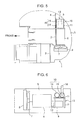
FIG. 3 is a side view enlargedly illustrating the area III encircled by the broken line inFIG. 2 . -
FIG. 4 is a side view illustrating an installed state of an exhaust gas aftertreatment device according to another embodiment of the present invention. -
FIG. 5 is a schematic top plan view of an upper slewing body of a conventional hydraulic shovel. -
FIG. 6 is a back view of an engine compartment provided on a rear region of the upper slewing body illustrated inFIG. 5 . - With reference to the accompanying drawing, the present invention will now be described based on embodiments thereof. It is to be understood that the following description is made to exemplify some embodiments of the present invention and is not intended to limit the scope of the present invention.
- With reference to
FIGS. 1 to 4 , one embodiment of the present invention will be described. - This embodiment is one example where the present invention is applied to a shovel in which an exhaust
gas aftertreatment device 20 is installed on a rear region of an upper slewing body, in the same manner as that in the conventional shovel illustrated inFIGS. 5 and 6 . - Specifically, the shovel comprises a lower traveling body, and an upper slewing body mounted on the lower traveling body.
- The upper slewing body comprises an
upper frame 1 as a base thereof, and a non-illustrated working attachment attached to one end portion (inFIG. 5 , left end portion) of the upper frame 1 (The following description will be made on an assumption that this end portion is a "front" end portion). The working attachment includes a boom, an arm and a bucket. - The upper slewing body further comprises:
partition walls 2 to 4 each extending in a right-left direction; anengine 6; a combination of acooling fan 7 and aheat exchanger 8 as cooling equipment; ahydraulic pump 9; and an exhaust gas aftertreatment device 20 (seeFIG. 1 ). - The
partition walls 2 to 4 define anengine compartment 5 on a rear region of theupper frame 1. Within theengine compartment 5, theengine 6 is provided, and thecooling fan 7 and theheat exchanger 8 such as a radiator are installed on a left side of theengine 6. - The
hydraulic pump 9 is provided on a right side of theengine 6 while being connected to an output shaft of theengine 6, and the exhaust gas aftertreatment device 20 (an aftermentioned exhaust gas purifyingdevice 21 and adevice body 23 of an aftermentioned NOx reducing device 22) is installed on the right side of theengine 6 in a posture where the exhaustgas aftertreatment device 20 extends transversely across an upper side of thehydraulic pump 9. - Referring to
FIGS. 1 and3 , the exhaustgas aftertreatment device 20 comprises: an exhaust gas purifyingdevice 21 comprised of a DPF (Diesel Particulate Filter) for removing PM (Particulate Matter) such as soot contained in exhaust gas and provided in an engine exhaust passage; and aNOx reducing device 22 comprised of an SCR (Selective Catalytic Reduction) system for decreasing NOx emissions and provided in the engine exhaust passage at a position downstream of the exhaust gas purifyingdevice 21. The exhaust gas purifyingdevice 21 and theaftermentioned device body 23 of theNOx reducing device 22 are arranged in side-by-side relation in the right-left direction. - The
NOx reducing device 22 comprises: adevice body 23 configured to allow execution of a urea-based SCR reaction for NOx, wherein thedevice body 23 has an exhaust gas outlet end portion(aftermentionedoutlet end cover 23c); atail pipe 27 provided at the outlet end portion of thedevice body 23 to release treated exhaust gas from thedevice body 23 to the outside; aNOx sensor 24 configured to detect an amount of NOx in exhaust gas; an aqueous urea solution injection control section (Dosing Control Unit: DCU) 25 configured to control an injection amount of an aqueous urea solution; aNOx controller 26 configured to send, as NOx information, a signal from theNOx sensor 24, to the aqueous urea solutioninjection control section 25; and a mount table 30 supporting thedevice body 23. Depending on an amount of NOx contained in exhaust gas, an amount of the aqueous urea solution to be injected into an inside of thedevice body 23 is controlled by theNOx reducing device 22. - The
device body 23 comprises: acasing 23a internally equipped with a urea-based SCR catalyst and an oxidation catalyst; and aninlet end cover 23b and anoutlet end cover 23c provided on respective opposite sides of thecasing 23a. - The
tail pipe 27 is provided in a central region of an edge face of theoutlet end cover 23c. In this embodiment, thetail pipe 27 is formed in a V shape which has a first portion gradually extending obliquely downwardly from theoutlet end cover 23c in a lateral (rearward) direction, and a second portion gradually extending obliquely upwardly from a distal end of the first portion in the lateral (rearward) direction. That is, theentire tail pipe 27 is disposed close to an aftermentionedtop plate 28 of the mount table 30, and, particularly, an intermediate region of thetail pipe 27 is disposed closest to the aftermentionedtop plate 28. - The mount table 30 supports the exhaust gas purifying
device 21 and thedevice body 23. Specifically, the mount table 30 comprises atop plate 28, and a plurality of (in this embodiment, total four)legs 29 supporting thetop plate 28. The mount table 30 are arranged to stride over thehydraulic pump 9. The exhaust gas purifyingdevice 21 and thedevice body 23 of theNOx reducing device 22 are installed on thetop plate 28 in side-by-side relation. That is, thedevice body 23 and thetail pipe 27 are provided on an upper side of thetop plate 28. - Each of the
top plate 28 and thelegs 29 may be made of a commonly-used metal material such as steel sheet. In particular, thetop plate 28 may be made of a raw material having at least one of heat resisting properties and heat shielding properties. - The
top plate 28 has a device-body support portion 28b with a reference surface (upper surface) A supporting thedevice body 23, and a NOx-controller installation portion 28a with alower surface 28c provided with theNOx controller 26. In this embodiment, the reference surface A supports the exhaustgas purifying device 21 and thedevice body 23 of theNOx reducing device 22. - The NOx-
controller installation portion 28a is coupled to a side edge (rear edge) of the device-body support portion 28b through a step portion B, so as to allow an upper surface of the NOx-controller installation portion 28a to be located below the upper surface (reference surface A) of the device-body support portion 28b, and allow thelower surface 28c of the NOx-controller installation portion 28a to be located below a lower surface of the device-body support portion 28b. - In this embodiment, the
device body 23 is supported by the device-body support portion 28b, in a posture where thetail pipe 27 extends laterally (approximately horizontally: backwardly in this embodiment) from thedevice body 23. Further, thetop plate 28 has an outlet-side end region (rear end region) provided at a position offset from thedevice body 23 on a tail pipe side of thedevice body 23 where the tail pipe is provided (offset rearwardly from the device body 23), and the NOx-controller installation portion 28a is provided with respect to the outlet-side end region of thetop plate 28. - The
NOx controller 26 is attached to thelower surface 28c of thetop plate 28 in such a manner that theNOx controller 26 is entirely covered from thereabove by the top plate 28 (NOx-controller installation portion 28a), and an air layer S is formed between theNOx controller 26 and thelower surface 28c of thetop plate 28. - Specifically, the
NOx controller 26 is attached in the above state by providing a pair ofelongated nuts lower surface 28c of the NOx-controller installation portion 28a to protrude downwardly, and, after penetratingly inserting twobolts NOx controller 26 from therebelow, screwing thebolts elongated nuts - As above, the
NOx controller 26 is provided with respect to thelower surface 28c of the top plate 28 (NOx-controller installation portion 28a) in such a manner that theNOx controller 26 is entirely covered from thereabove by the NOx-controller installation portion 28a. Therefore, it becomes possible to protect theNOx controller 26 against heat and water by utilizing the NOx-controller installation portion 28a as a heat shielding plate and a water-protection roof. - The utilization of the
top plate 28 of the mount table 30 as a protective member also makes it possible to eliminate a need for an extra heat insulating material or cover, and allow theNOx controller 26 and thedevice body 23 to be preliminarily installed to thetop plate 28 and then assembled to an installation site in the form of an integrated unit (so-called "sub-assembling"). This is advantageous in terms of cost of the shovel and assemblability (installability) of theNOx controller 26. - That is, it becomes possible to effectively protect the
NOx controller 26 against heat and water, without causing negative effects such as an increase in cost of the shovel and deterioration in assemblability of theNOx controller 26. - Further, the NOx-
controller installation portion 28a is coupled to the side edge of the device-body support portion 28b through the step portion B, so as to allow the upper surface of the NOx-controller installation portion 28a to be located below the upper surface of the device-body support portion 28b, and allow thelower surface 28c of the NOx-controller installation portion 28a to be located below the lower surface of the device-body support portion 28b. Therefore, theNOx controller 26 can be disposed away from a heat source (device body 23 and tail pipe 27). This allows the heat protection effect (protective effect against heat) to be further enhanced. - This effect becomes particularly effective in the situation where the
tail pipe 27 as a heat source is formed in a V shape, and thetail pipe 27 is disposed to extend from the central region of the outlet end face of thedevice body 23 to come close to thetop plate 28, as in this embodiment. - Further, the NOx-
controller installation portion 28a is provided in a region offset laterally (backwardly) from thedevice body 23 and having a low possibility of the existence of a structure hindering installation of theNOx controller 26, so that the installation of theNOx controller 26 becomes easier. - In other words, because the NOx-
controller installation portion 28a allows theNOx controller 26 to be reliably protected against heat damage, it becomes possible to install theNOx controller 26 at a position where it can be easily installed without any concern for heat from thetail pipe 27. - Furthermore, the
NOx controller 26 is provided in such a manner that the air layer S is formed between theNOx controller 26 and thelower surface 28c of thetop plate 28, so that, based on a heat insulating effect of the air layer S, the heat protection effect can be further enhanced. - (1) As illustrated in
FIG. 4 , the NOx-controller installation portion 28a of thetop plate 28 of the mount table 30 may be coupled to a remaining portion of thetop plate 28 without interposing the step portion therebetween, i.e., coupled in such a manner as to become flush with the remaining portion, and theNOx controller 26 may be installed with respect to the lower surface of the NOx-controller installation portion 28a. - This makes it possible to eliminate a need to perform a working for forming the step portion in the
top plate 28, so that it becomes possible to keep a production cost at a low level. - Even in this case, as a fundamental effect, it is possible to protect the
NOx controller 26 against heat and water, based on heat shielding and water protection actions of the top plate 28 (NOx-controller installation portion 28a). - Particularly, this configuration is preferable in the case where the
tail pipe 27 is formed in an L shape which has a first portion extending laterally (approximately horizontally) from theoutlet end cover 23c, and a second portion extending upwardly from a distal end of the first portion, as illustrated inFIG. 4 (i.e., in the case where a distance between thetail pipe 27 and theNOx controller 26 is greater than that in the aforementioned embodiment). - (2) The
NOx controller 26 may be installed with respect to a lower surface of a portion of thetop plate 28 on which thedevice body 23 is installed (e.g., the device-body support portion 28b). - (3) As an installation structure of the
NOx controller 26 with respect to the lower surface of thetop plate 28, any suitable structure other than that in the above embodiment may be employed. For example, it is possible to employ a structure in which an elongated nut is provided on an upper surface of theNOx controller 26 to protrude upwardly, and theNOx controller 26 is installed with respect to thetop plate 28 by using a bolt penetratingly inserted into thetop plate 28 from thereabove. - The
NOx controller 26 may be directly installed to the lower surface of the top plate 28 (without forming theair layer 5 therebetween). - (4) In the aforementioned embodiment, only one
NOx controller 26 is installed with respect to the lower surface of thetop plate 28. In the case where a plurality of NOx controllers are provided, all of the NOx controllers may be installed with respect to the lower surface of thetop plate 28. - (5) In addition to a shovel, the present invention can be widely applied to a construction machine provided with a NOx reducing device with a NOx controller.
- The above specific embodiments primarily include an invention having the following features.
- In order to achieve the aforementioned object, the present invention provides a NOx reducing device which is provided for a construction machine having an engine to serve as an exhaust gas aftertreatment device for treating exhaust gas from the engine to decrease NOx in the exhaust gas by using an aqueous urea solution. The NOx reducing device comprises: a device body configured to allow execution of a urea-based selective catalytic reduction (SCR) reaction for the NOx, wherein the device body has an outlet end portion; a tail pipe provided at the outlet end portion; an aqueous urea solution injection control section configured to control an injection amount of an aqueous urea solution; a NOx sensor configured to detect an amount of NOx in the exhaust gas; a NOx controller configured to send, as NOx information, a signal from the NOx sensor, to the aqueous urea solution injection control section; and a mount table supporting the device body, wherein the mount table comprises a top plate and a leg supporting the top plate. In the NOx reducing device, the device body and the tail pipe are provided on an upper side of the top plate, and the NOx controller is provided with respect to a lower surface of the top plate in such a manner that the NOx controller is entirely covered from thereabove by the top plate.
- In the present invention, the NOx controller is installed with respect to the lower surface of the top plate of the mount table in such a manner that the NOx controller is entirely covered from thereabove by the top plate, so that it becomes possible to effectively protect the NOx controller against heat and water by utilizing the top plate as a heat shielding plate and a water-protection roof.
- The utilization of the top plate of the mount table as a protective member also makes it possible to eliminate a need for an extra heat insulating material or cover, and allow the NOx controller and the device body to be preliminarily installed to the top plate and then assembled to an installation site in the form of an integrated unit (so-called "sub-assembling"). This is advantageous in terms of cost of the construction machine and assemblability (installability) of the NOx controller.
- Preferably, in the NOx reducing device, the top plate has a device-body support portion with an upper surface supporting the device body, and a NOx-controller installation portion with a lower surface provided with the NOx controller, wherein the NOx-controller installation portion is coupled to a side edge of the device-body support portion through a step portion, so as to allow an upper surface of the NOx-controller installation portion to be located below the upper surface of the device-body support portion, and allow the lower surface of the NOx-controller installation portion to be located below a lower surface of the device-body support portion.
- According to this aspect, the NOx controller can be disposed away from a heat source (device body and tail pipe). This allows the heat protection effect to be further enhanced.
- Preferably, in the above NOx reducing device, the device body is supported by the device-body support portion, in a posture where the tail pipe extends laterally from the device body, wherein the top plate has an end region provided at a position offset from the device body on a tail pipe side of the device body where the tail pipe is provided, and the NOx-controller installation portion is provided with respect to the end region of the top plate. This aspect becomes particularly effective in a situation where the tail pipe is disposed in adjacent relation to the top plate, because NOx-controller can be disposed below the tail pipe and at a position away from the tail pipe.
- Further, according to this aspect, the NOx controller is provided with respect to the end region of the top plate offset from the device body on a tail pipe side of the device body where the tail pipe is provided, i.e., at a position having a low possibility of the existence of an obstacle to installation of the NOx controller, so that the installation of the NOx controller becomes easier.
- In other words, because the NOx-controller installation portion allows the NOx controller to be reliably protected against heat damage, it becomes possible to install the NOx controller at a position where it can be easily installed without any concern for heat from the tail pipe.
- Preferably, in the NOx reducing device, the NOx controller is provided with respect to the lower surface of the top plate, in such a manner that an air layer is formed between the NOx controller and the lower surface of the top plate.
- According to this aspect, the heat protection effect can be further enhanced based on a heat insulating effect of the air layer.
- This application is based on Japanese Patent application No.
2013-272367 - Although the present invention has been fully described by way of example with reference to the accompanying drawings, it is to be understood that various changes and modifications will be apparent to those skilled in the art. Therefore, unless otherwise such changes and modifications depart from the scope of the present invention hereinafter defined, they should be construed as being included therein.
- Provided is a NOx reducing device which is capable of effectively protecting a NOx controller against heat and water, while suppressing an increase in cost of a construction machine and deterioration in assemblability of the NOx controller. The NOx reducing device (22) comprises a device body (23), a tail pipe (27) provided at an outlet end portion of the device body (23), a NOx controller (26), and a mount table (30) supporting the device body (23). The mount table (30) comprises a top plate (28) and a leg (29) supporting the top plate (28). The device body (23) and the tail pipe (27) are provided on an upper side of the top plate (28). The NOx controller (26) is provided with respect to a lower surface (28c) of the top plate (28) in such a manner that the NOx controller (26) is entirely covered from thereabove by the top plate (28).
Claims (4)
- A NOx reducing device provided for a construction machine having an engine to serve as an exhaust gas aftertreatment device for treating exhaust gas from the engine to decrease NOx in the exhaust gas by using an aqueous urea solution, comprising:a device body configured to allow execution of a urea-based selective catalytic reduction reaction for the NOx, the device body having an outlet end portion;a tail pipe provided at the outlet end portion;an aqueous urea solution injection control section configured to control an injection amount of an aqueous urea solution;a NOx sensor configured to detect an amount of NOx in the exhaust gas;a NOx controller configured to send, as NOx information, a signal from the NOx sensor, to the aqueous urea solution injection control section; anda mount table supporting the device body,whereinthe mount table comprises a top plate and a leg supporting the top plate,the device body and the tail pipe are provided on an upper side of the top plate, andthe NOx controller is provided with respect to a lower surface of the top plate in such a manner that the NOx controller is entirely covered from thereabove by the top plate.
- The NOx reducing device according to claim 1, wherein
the top plate has a device-body support portion with an upper surface supporting the device body, and a NOx-controller installation portion with a lower surface provided with the NOx controller, and
the NOx-controller installation portion is coupled to a side edge of the device-body support portion through a step portion, so as to allow an upper surface of the NOx-controller installation portion to be located below the upper surface of the device-body support portion, and allow the lower surface of the NOx-controller installation portion to be located below a lower surface of the device-body support portion. - The NOx reducing device according to claim 2, wherein:the device body is supported by the device-body support portion, in a posture where the tail pipe extends laterally from the device body;the top plate has an end region provided at a position offset from the device body on a tail pipe side of the device body where the tail pipe is provided; andthe NOx-controller installation portion is provided with respect to the end region of the top plate.
- The NOx reducing device according to any one of claims 1 to 3, wherein the NOx controller is provided with respect to the lower surface of the top plate, in such a manner that an air layer is formed between the NOx controller and the lower surface of the top plate.
Applications Claiming Priority (1)
| Application Number | Priority Date | Filing Date | Title |
|---|---|---|---|
| JP2013272367A JP5895931B2 (en) | 2013-12-27 | 2013-12-27 | Construction machinery |
Publications (2)
| Publication Number | Publication Date |
|---|---|
| EP2889461A1 true EP2889461A1 (en) | 2015-07-01 |
| EP2889461B1 EP2889461B1 (en) | 2017-08-02 |
Family
ID=52101067
Family Applications (1)
| Application Number | Title | Priority Date | Filing Date |
|---|---|---|---|
| EP14196787.7A Active EP2889461B1 (en) | 2013-12-27 | 2014-12-08 | NOx reducing device |
Country Status (3)
| Country | Link |
|---|---|
| US (1) | US9429056B2 (en) |
| EP (1) | EP2889461B1 (en) |
| JP (1) | JP5895931B2 (en) |
Families Citing this family (5)
| Publication number | Priority date | Publication date | Assignee | Title |
|---|---|---|---|---|
| JP6190182B2 (en) * | 2013-06-28 | 2017-08-30 | 株式会社タダノ | Exhaust purification system for rough terrain cranes |
| US10377227B2 (en) * | 2014-08-21 | 2019-08-13 | Mitsubishi Logisnext Co., LTD. | Industrial vehicle |
| JP2017053315A (en) * | 2015-09-11 | 2017-03-16 | コベルコ建機株式会社 | Exhaust gas after-treatment device and construction machine including the same |
| CA2934750C (en) * | 2016-03-31 | 2017-07-04 | Takamu Kanayama | Dump truck |
| DE102017130866A1 (en) * | 2017-12-21 | 2019-06-27 | Faurecia Emissions Control Technologies, Germany Gmbh | Exhaust system for an internal combustion engine of a motor vehicle and motor vehicle |
Citations (4)
| Publication number | Priority date | Publication date | Assignee | Title |
|---|---|---|---|---|
| US20100031644A1 (en) * | 2008-08-07 | 2010-02-11 | Caterpillar Inc. | Mounting assembly for emissions control system |
| US20130145820A1 (en) * | 2011-12-12 | 2013-06-13 | Caterpillar Inc. | Sensor mounting arrangement |
| JP2013224542A (en) | 2012-04-20 | 2013-10-31 | Kobelco Contstruction Machinery Ltd | Working machine |
| EP2801711A1 (en) * | 2012-01-06 | 2014-11-12 | Volvo Construction Equipment AB | Exhaust gas reduction device for heavy equipment |
Family Cites Families (9)
| Publication number | Priority date | Publication date | Assignee | Title |
|---|---|---|---|---|
| JP4153113B2 (en) * | 1998-12-04 | 2008-09-17 | 株式会社デンソー | Gas concentration detector |
| JP4689357B2 (en) * | 2005-06-08 | 2011-05-25 | 株式会社小松製作所 | Work vehicle |
| JP4739104B2 (en) * | 2006-04-21 | 2011-08-03 | 日本特殊陶業株式会社 | Sensor control device |
| JPWO2008136203A1 (en) * | 2007-05-01 | 2010-07-29 | 日立建機株式会社 | Construction machinery |
| JP5006740B2 (en) * | 2007-09-13 | 2012-08-22 | ヤンマー株式会社 | Black smoke purification device for diesel engine |
| JP2009210299A (en) * | 2008-02-29 | 2009-09-17 | Sumitomo Electric Ind Ltd | NOx SENSOR, EXHAUST EMISSION CONTROL SYSTEM, AND NOx MEASURING METHOD |
| EP2302180B1 (en) * | 2008-07-10 | 2014-04-30 | Hitachi Construction Machinery Co., Ltd | Construction machine |
| US20100186381A1 (en) * | 2009-01-26 | 2010-07-29 | Caterpillar Inc | Exhaust system thermal enclosure |
| JP2010270555A (en) * | 2009-05-25 | 2010-12-02 | Kobelco Contstruction Machinery Ltd | Frame for working machine |
-
2013
- 2013-12-27 JP JP2013272367A patent/JP5895931B2/en active Active
-
2014
- 2014-12-02 US US14/557,555 patent/US9429056B2/en active Active
- 2014-12-08 EP EP14196787.7A patent/EP2889461B1/en active Active
Patent Citations (4)
| Publication number | Priority date | Publication date | Assignee | Title |
|---|---|---|---|---|
| US20100031644A1 (en) * | 2008-08-07 | 2010-02-11 | Caterpillar Inc. | Mounting assembly for emissions control system |
| US20130145820A1 (en) * | 2011-12-12 | 2013-06-13 | Caterpillar Inc. | Sensor mounting arrangement |
| EP2801711A1 (en) * | 2012-01-06 | 2014-11-12 | Volvo Construction Equipment AB | Exhaust gas reduction device for heavy equipment |
| JP2013224542A (en) | 2012-04-20 | 2013-10-31 | Kobelco Contstruction Machinery Ltd | Working machine |
Also Published As
| Publication number | Publication date |
|---|---|
| JP2015124773A (en) | 2015-07-06 |
| US9429056B2 (en) | 2016-08-30 |
| EP2889461B1 (en) | 2017-08-02 |
| JP5895931B2 (en) | 2016-03-30 |
| US20150184568A1 (en) | 2015-07-02 |
Similar Documents
| Publication | Publication Date | Title |
|---|---|---|
| EP2889461B1 (en) | NOx reducing device | |
| EP2842783B1 (en) | Work vehicle | |
| US8973353B2 (en) | Exhaust gas post-treatment unit and construction vehicle carrying same | |
| JP3751962B2 (en) | Engine exhaust purification system | |
| EP3156623B1 (en) | Exhaust aftertreatment sensor assembly | |
| WO2009142058A1 (en) | Construction machine | |
| US10940752B2 (en) | Industrial vehicle | |
| EP3009759B1 (en) | Utility vehicle | |
| EP3239411B1 (en) | Operation machine | |
| JPWO2014155510A1 (en) | Wheel loader | |
| WO2014155506A1 (en) | Wheel loader | |
| JPWO2014155505A1 (en) | Work vehicle and wheel loader | |
| JP2017002582A (en) | Construction machine | |
| JP4925877B2 (en) | Construction vehicle | |
| EP3222830B1 (en) | Industrial vehicle | |
| JP2012246771A (en) | Arrangement structure of exhaust emission control device for engine driven working machine | |
| US20160153173A1 (en) | Work vehicle | |
| JP6451241B2 (en) | Construction machinery | |
| JP2014125868A (en) | Counterweight, construction machinery, and control method for construction machinery | |
| JP6176297B2 (en) | Construction machinery | |
| JP5756880B2 (en) | Wheel loader | |
| JP5855557B2 (en) | Construction machinery | |
| JP2017053315A (en) | Exhaust gas after-treatment device and construction machine including the same | |
| JP2019043274A (en) | Rear part structure of rear engine vehicle | |
| JP6765994B2 (en) | Excavator |
Legal Events
| Date | Code | Title | Description |
|---|---|---|---|
| PUAI | Public reference made under article 153(3) epc to a published international application that has entered the european phase |
Free format text: ORIGINAL CODE: 0009012 |
|
| 17P | Request for examination filed |
Effective date: 20141208 |
|
| AK | Designated contracting states |
Kind code of ref document: A1 Designated state(s): AL AT BE BG CH CY CZ DE DK EE ES FI FR GB GR HR HU IE IS IT LI LT LU LV MC MK MT NL NO PL PT RO RS SE SI SK SM TR |
|
| AX | Request for extension of the european patent |
Extension state: BA ME |
|
| R17P | Request for examination filed (corrected) |
Effective date: 20151216 |
|
| RBV | Designated contracting states (corrected) |
Designated state(s): AL AT BE BG CH CY CZ DE DK EE ES FI FR GB GR HR HU IE IS IT LI LT LU LV MC MK MT NL NO PL PT RO RS SE SI SK SM TR |
|
| GRAJ | Information related to disapproval of communication of intention to grant by the applicant or resumption of examination proceedings by the epo deleted |
Free format text: ORIGINAL CODE: EPIDOSDIGR1 |
|
| GRAP | Despatch of communication of intention to grant a patent |
Free format text: ORIGINAL CODE: EPIDOSNIGR1 |
|
| GRAP | Despatch of communication of intention to grant a patent |
Free format text: ORIGINAL CODE: EPIDOSNIGR1 |
|
| RIC1 | Information provided on ipc code assigned before grant |
Ipc: F01N 13/18 20100101ALI20170120BHEP Ipc: E02F 9/08 20060101ALI20170120BHEP Ipc: B60K 13/04 20060101ALI20170120BHEP Ipc: F01N 3/20 20060101AFI20170120BHEP |
|
| INTG | Intention to grant announced |
Effective date: 20170223 |
|
| GRAS | Grant fee paid |
Free format text: ORIGINAL CODE: EPIDOSNIGR3 |
|
| GRAA | (expected) grant |
Free format text: ORIGINAL CODE: 0009210 |
|
| AK | Designated contracting states |
Kind code of ref document: B1 Designated state(s): AL AT BE BG CH CY CZ DE DK EE ES FI FR GB GR HR HU IE IS IT LI LT LU LV MC MK MT NL NO PL PT RO RS SE SI SK SM TR |
|
| REG | Reference to a national code |
Ref country code: CH Ref legal event code: EP Ref country code: AT Ref legal event code: REF Ref document number: 914742 Country of ref document: AT Kind code of ref document: T Effective date: 20170815 |
|
| REG | Reference to a national code |
Ref country code: IE Ref legal event code: FG4D |
|
| REG | Reference to a national code |
Ref country code: DE Ref legal event code: R096 Ref document number: 602014012476 Country of ref document: DE |
|
| REG | Reference to a national code |
Ref country code: NL Ref legal event code: MP Effective date: 20170802 |
|
| REG | Reference to a national code |
Ref country code: AT Ref legal event code: MK05 Ref document number: 914742 Country of ref document: AT Kind code of ref document: T Effective date: 20170802 |
|
| REG | Reference to a national code |
Ref country code: FR Ref legal event code: PLFP Year of fee payment: 4 |
|
| REG | Reference to a national code |
Ref country code: LT Ref legal event code: MG4D |
|
| PG25 | Lapsed in a contracting state [announced via postgrant information from national office to epo] |
Ref country code: NL Free format text: LAPSE BECAUSE OF FAILURE TO SUBMIT A TRANSLATION OF THE DESCRIPTION OR TO PAY THE FEE WITHIN THE PRESCRIBED TIME-LIMIT Effective date: 20170802 Ref country code: LT Free format text: LAPSE BECAUSE OF FAILURE TO SUBMIT A TRANSLATION OF THE DESCRIPTION OR TO PAY THE FEE WITHIN THE PRESCRIBED TIME-LIMIT Effective date: 20170802 Ref country code: NO Free format text: LAPSE BECAUSE OF FAILURE TO SUBMIT A TRANSLATION OF THE DESCRIPTION OR TO PAY THE FEE WITHIN THE PRESCRIBED TIME-LIMIT Effective date: 20171102 Ref country code: AT Free format text: LAPSE BECAUSE OF FAILURE TO SUBMIT A TRANSLATION OF THE DESCRIPTION OR TO PAY THE FEE WITHIN THE PRESCRIBED TIME-LIMIT Effective date: 20170802 Ref country code: HR Free format text: LAPSE BECAUSE OF FAILURE TO SUBMIT A TRANSLATION OF THE DESCRIPTION OR TO PAY THE FEE WITHIN THE PRESCRIBED TIME-LIMIT Effective date: 20170802 Ref country code: FI Free format text: LAPSE BECAUSE OF FAILURE TO SUBMIT A TRANSLATION OF THE DESCRIPTION OR TO PAY THE FEE WITHIN THE PRESCRIBED TIME-LIMIT Effective date: 20170802 Ref country code: SE Free format text: LAPSE BECAUSE OF FAILURE TO SUBMIT A TRANSLATION OF THE DESCRIPTION OR TO PAY THE FEE WITHIN THE PRESCRIBED TIME-LIMIT Effective date: 20170802 |
|
| PG25 | Lapsed in a contracting state [announced via postgrant information from national office to epo] |
Ref country code: GR Free format text: LAPSE BECAUSE OF FAILURE TO SUBMIT A TRANSLATION OF THE DESCRIPTION OR TO PAY THE FEE WITHIN THE PRESCRIBED TIME-LIMIT Effective date: 20171103 Ref country code: ES Free format text: LAPSE BECAUSE OF FAILURE TO SUBMIT A TRANSLATION OF THE DESCRIPTION OR TO PAY THE FEE WITHIN THE PRESCRIBED TIME-LIMIT Effective date: 20170802 Ref country code: LV Free format text: LAPSE BECAUSE OF FAILURE TO SUBMIT A TRANSLATION OF THE DESCRIPTION OR TO PAY THE FEE WITHIN THE PRESCRIBED TIME-LIMIT Effective date: 20170802 Ref country code: PL Free format text: LAPSE BECAUSE OF FAILURE TO SUBMIT A TRANSLATION OF THE DESCRIPTION OR TO PAY THE FEE WITHIN THE PRESCRIBED TIME-LIMIT Effective date: 20170802 Ref country code: RS Free format text: LAPSE BECAUSE OF FAILURE TO SUBMIT A TRANSLATION OF THE DESCRIPTION OR TO PAY THE FEE WITHIN THE PRESCRIBED TIME-LIMIT Effective date: 20170802 Ref country code: IS Free format text: LAPSE BECAUSE OF FAILURE TO SUBMIT A TRANSLATION OF THE DESCRIPTION OR TO PAY THE FEE WITHIN THE PRESCRIBED TIME-LIMIT Effective date: 20171202 Ref country code: BG Free format text: LAPSE BECAUSE OF FAILURE TO SUBMIT A TRANSLATION OF THE DESCRIPTION OR TO PAY THE FEE WITHIN THE PRESCRIBED TIME-LIMIT Effective date: 20171102 |
|
| PG25 | Lapsed in a contracting state [announced via postgrant information from national office to epo] |
Ref country code: RO Free format text: LAPSE BECAUSE OF FAILURE TO SUBMIT A TRANSLATION OF THE DESCRIPTION OR TO PAY THE FEE WITHIN THE PRESCRIBED TIME-LIMIT Effective date: 20170802 Ref country code: DK Free format text: LAPSE BECAUSE OF FAILURE TO SUBMIT A TRANSLATION OF THE DESCRIPTION OR TO PAY THE FEE WITHIN THE PRESCRIBED TIME-LIMIT Effective date: 20170802 Ref country code: CZ Free format text: LAPSE BECAUSE OF FAILURE TO SUBMIT A TRANSLATION OF THE DESCRIPTION OR TO PAY THE FEE WITHIN THE PRESCRIBED TIME-LIMIT Effective date: 20170802 |
|
| REG | Reference to a national code |
Ref country code: DE Ref legal event code: R097 Ref document number: 602014012476 Country of ref document: DE |
|
| PG25 | Lapsed in a contracting state [announced via postgrant information from national office to epo] |
Ref country code: SK Free format text: LAPSE BECAUSE OF FAILURE TO SUBMIT A TRANSLATION OF THE DESCRIPTION OR TO PAY THE FEE WITHIN THE PRESCRIBED TIME-LIMIT Effective date: 20170802 Ref country code: SM Free format text: LAPSE BECAUSE OF FAILURE TO SUBMIT A TRANSLATION OF THE DESCRIPTION OR TO PAY THE FEE WITHIN THE PRESCRIBED TIME-LIMIT Effective date: 20170802 Ref country code: EE Free format text: LAPSE BECAUSE OF FAILURE TO SUBMIT A TRANSLATION OF THE DESCRIPTION OR TO PAY THE FEE WITHIN THE PRESCRIBED TIME-LIMIT Effective date: 20170802 |
|
| PLBE | No opposition filed within time limit |
Free format text: ORIGINAL CODE: 0009261 |
|
| STAA | Information on the status of an ep patent application or granted ep patent |
Free format text: STATUS: NO OPPOSITION FILED WITHIN TIME LIMIT |
|
| 26N | No opposition filed |
Effective date: 20180503 |
|
| REG | Reference to a national code |
Ref country code: CH Ref legal event code: PL |
|
| PG25 | Lapsed in a contracting state [announced via postgrant information from national office to epo] |
Ref country code: SI Free format text: LAPSE BECAUSE OF FAILURE TO SUBMIT A TRANSLATION OF THE DESCRIPTION OR TO PAY THE FEE WITHIN THE PRESCRIBED TIME-LIMIT Effective date: 20170802 |
|
| REG | Reference to a national code |
Ref country code: IE Ref legal event code: MM4A |
|
| PG25 | Lapsed in a contracting state [announced via postgrant information from national office to epo] |
Ref country code: LU Free format text: LAPSE BECAUSE OF NON-PAYMENT OF DUE FEES Effective date: 20171208 Ref country code: MT Free format text: LAPSE BECAUSE OF NON-PAYMENT OF DUE FEES Effective date: 20171208 |
|
| REG | Reference to a national code |
Ref country code: BE Ref legal event code: MM Effective date: 20171231 |
|
| PG25 | Lapsed in a contracting state [announced via postgrant information from national office to epo] |
Ref country code: IE Free format text: LAPSE BECAUSE OF NON-PAYMENT OF DUE FEES Effective date: 20171208 |
|
| PG25 | Lapsed in a contracting state [announced via postgrant information from national office to epo] |
Ref country code: BE Free format text: LAPSE BECAUSE OF NON-PAYMENT OF DUE FEES Effective date: 20171231 Ref country code: LI Free format text: LAPSE BECAUSE OF NON-PAYMENT OF DUE FEES Effective date: 20171231 Ref country code: CH Free format text: LAPSE BECAUSE OF NON-PAYMENT OF DUE FEES Effective date: 20171231 |
|
| PG25 | Lapsed in a contracting state [announced via postgrant information from national office to epo] |
Ref country code: MC Free format text: LAPSE BECAUSE OF FAILURE TO SUBMIT A TRANSLATION OF THE DESCRIPTION OR TO PAY THE FEE WITHIN THE PRESCRIBED TIME-LIMIT Effective date: 20170802 Ref country code: HU Free format text: LAPSE BECAUSE OF FAILURE TO SUBMIT A TRANSLATION OF THE DESCRIPTION OR TO PAY THE FEE WITHIN THE PRESCRIBED TIME-LIMIT; INVALID AB INITIO Effective date: 20141208 |
|
| PG25 | Lapsed in a contracting state [announced via postgrant information from national office to epo] |
Ref country code: CY Free format text: LAPSE BECAUSE OF FAILURE TO SUBMIT A TRANSLATION OF THE DESCRIPTION OR TO PAY THE FEE WITHIN THE PRESCRIBED TIME-LIMIT Effective date: 20170802 |
|
| PG25 | Lapsed in a contracting state [announced via postgrant information from national office to epo] |
Ref country code: MK Free format text: LAPSE BECAUSE OF FAILURE TO SUBMIT A TRANSLATION OF THE DESCRIPTION OR TO PAY THE FEE WITHIN THE PRESCRIBED TIME-LIMIT Effective date: 20170802 |
|
| PG25 | Lapsed in a contracting state [announced via postgrant information from national office to epo] |
Ref country code: TR Free format text: LAPSE BECAUSE OF FAILURE TO SUBMIT A TRANSLATION OF THE DESCRIPTION OR TO PAY THE FEE WITHIN THE PRESCRIBED TIME-LIMIT Effective date: 20170802 |
|
| PG25 | Lapsed in a contracting state [announced via postgrant information from national office to epo] |
Ref country code: PT Free format text: LAPSE BECAUSE OF FAILURE TO SUBMIT A TRANSLATION OF THE DESCRIPTION OR TO PAY THE FEE WITHIN THE PRESCRIBED TIME-LIMIT Effective date: 20170802 |
|
| PG25 | Lapsed in a contracting state [announced via postgrant information from national office to epo] |
Ref country code: AL Free format text: LAPSE BECAUSE OF FAILURE TO SUBMIT A TRANSLATION OF THE DESCRIPTION OR TO PAY THE FEE WITHIN THE PRESCRIBED TIME-LIMIT Effective date: 20170802 |
|
| PGFP | Annual fee paid to national office [announced via postgrant information from national office to epo] |
Ref country code: IT Payment date: 20231110 Year of fee payment: 10 |
|
| PG25 | Lapsed in a contracting state [announced via postgrant information from national office to epo] |
Ref country code: IT Free format text: LAPSE BECAUSE OF NON-PAYMENT OF DUE FEES Effective date: 20241208 |
|
| PGFP | Annual fee paid to national office [announced via postgrant information from national office to epo] |
Ref country code: DE Payment date: 20251028 Year of fee payment: 12 |
|
| PGFP | Annual fee paid to national office [announced via postgrant information from national office to epo] |
Ref country code: GB Payment date: 20251030 Year of fee payment: 12 |
|
| PGFP | Annual fee paid to national office [announced via postgrant information from national office to epo] |
Ref country code: FR Payment date: 20251110 Year of fee payment: 12 |