EP2889460A1 - Diesel engine - Google Patents
Diesel engine Download PDFInfo
- Publication number
- EP2889460A1 EP2889460A1 EP14180589.5A EP14180589A EP2889460A1 EP 2889460 A1 EP2889460 A1 EP 2889460A1 EP 14180589 A EP14180589 A EP 14180589A EP 2889460 A1 EP2889460 A1 EP 2889460A1
- Authority
- EP
- European Patent Office
- Prior art keywords
- case
- exhaust gas
- dpf
- pipe
- scr catalyst
- Prior art date
- Legal status (The legal status is an assumption and is not a legal conclusion. Google has not performed a legal analysis and makes no representation as to the accuracy of the status listed.)
- Granted
Links
Images



Classifications
-
- F—MECHANICAL ENGINEERING; LIGHTING; HEATING; WEAPONS; BLASTING
- F01—MACHINES OR ENGINES IN GENERAL; ENGINE PLANTS IN GENERAL; STEAM ENGINES
- F01N—GAS-FLOW SILENCERS OR EXHAUST APPARATUS FOR MACHINES OR ENGINES IN GENERAL; GAS-FLOW SILENCERS OR EXHAUST APPARATUS FOR INTERNAL-COMBUSTION ENGINES
- F01N3/00—Exhaust or silencing apparatus having means for purifying, rendering innocuous, or otherwise treating exhaust
- F01N3/02—Exhaust or silencing apparatus having means for purifying, rendering innocuous, or otherwise treating exhaust for cooling, or for removing solid constituents of, exhaust
- F01N3/021—Exhaust or silencing apparatus having means for purifying, rendering innocuous, or otherwise treating exhaust for cooling, or for removing solid constituents of, exhaust by means of filters
- F01N3/033—Exhaust or silencing apparatus having means for purifying, rendering innocuous, or otherwise treating exhaust for cooling, or for removing solid constituents of, exhaust by means of filters in combination with other devices
- F01N3/035—Exhaust or silencing apparatus having means for purifying, rendering innocuous, or otherwise treating exhaust for cooling, or for removing solid constituents of, exhaust by means of filters in combination with other devices with catalytic reactors
-
- F—MECHANICAL ENGINEERING; LIGHTING; HEATING; WEAPONS; BLASTING
- F01—MACHINES OR ENGINES IN GENERAL; ENGINE PLANTS IN GENERAL; STEAM ENGINES
- F01N—GAS-FLOW SILENCERS OR EXHAUST APPARATUS FOR MACHINES OR ENGINES IN GENERAL; GAS-FLOW SILENCERS OR EXHAUST APPARATUS FOR INTERNAL-COMBUSTION ENGINES
- F01N13/00—Exhaust or silencing apparatus characterised by constructional features
- F01N13/009—Exhaust or silencing apparatus characterised by constructional features having two or more separate purifying devices arranged in series
-
- F—MECHANICAL ENGINEERING; LIGHTING; HEATING; WEAPONS; BLASTING
- F01—MACHINES OR ENGINES IN GENERAL; ENGINE PLANTS IN GENERAL; STEAM ENGINES
- F01N—GAS-FLOW SILENCERS OR EXHAUST APPARATUS FOR MACHINES OR ENGINES IN GENERAL; GAS-FLOW SILENCERS OR EXHAUST APPARATUS FOR INTERNAL-COMBUSTION ENGINES
- F01N13/00—Exhaust or silencing apparatus characterised by constructional features
- F01N13/18—Construction facilitating manufacture, assembly, or disassembly
- F01N13/1805—Fixing exhaust manifolds, exhaust pipes or pipe sections to each other, to engine or to vehicle body
-
- F—MECHANICAL ENGINEERING; LIGHTING; HEATING; WEAPONS; BLASTING
- F01—MACHINES OR ENGINES IN GENERAL; ENGINE PLANTS IN GENERAL; STEAM ENGINES
- F01N—GAS-FLOW SILENCERS OR EXHAUST APPARATUS FOR MACHINES OR ENGINES IN GENERAL; GAS-FLOW SILENCERS OR EXHAUST APPARATUS FOR INTERNAL-COMBUSTION ENGINES
- F01N3/00—Exhaust or silencing apparatus having means for purifying, rendering innocuous, or otherwise treating exhaust
- F01N3/02—Exhaust or silencing apparatus having means for purifying, rendering innocuous, or otherwise treating exhaust for cooling, or for removing solid constituents of, exhaust
- F01N3/021—Exhaust or silencing apparatus having means for purifying, rendering innocuous, or otherwise treating exhaust for cooling, or for removing solid constituents of, exhaust by means of filters
-
- F—MECHANICAL ENGINEERING; LIGHTING; HEATING; WEAPONS; BLASTING
- F01—MACHINES OR ENGINES IN GENERAL; ENGINE PLANTS IN GENERAL; STEAM ENGINES
- F01N—GAS-FLOW SILENCERS OR EXHAUST APPARATUS FOR MACHINES OR ENGINES IN GENERAL; GAS-FLOW SILENCERS OR EXHAUST APPARATUS FOR INTERNAL-COMBUSTION ENGINES
- F01N3/00—Exhaust or silencing apparatus having means for purifying, rendering innocuous, or otherwise treating exhaust
- F01N3/08—Exhaust or silencing apparatus having means for purifying, rendering innocuous, or otherwise treating exhaust for rendering innocuous
- F01N3/10—Exhaust or silencing apparatus having means for purifying, rendering innocuous, or otherwise treating exhaust for rendering innocuous by thermal or catalytic conversion of noxious components of exhaust
- F01N3/18—Exhaust or silencing apparatus having means for purifying, rendering innocuous, or otherwise treating exhaust for rendering innocuous by thermal or catalytic conversion of noxious components of exhaust characterised by methods of operation; Control
- F01N3/20—Exhaust or silencing apparatus having means for purifying, rendering innocuous, or otherwise treating exhaust for rendering innocuous by thermal or catalytic conversion of noxious components of exhaust characterised by methods of operation; Control specially adapted for catalytic conversion
- F01N3/206—Adding periodically or continuously substances to exhaust gases for promoting purification, e.g. catalytic material in liquid form, NOx reducing agents
- F01N3/2066—Selective catalytic reduction [SCR]
-
- F—MECHANICAL ENGINEERING; LIGHTING; HEATING; WEAPONS; BLASTING
- F01—MACHINES OR ENGINES IN GENERAL; ENGINE PLANTS IN GENERAL; STEAM ENGINES
- F01N—GAS-FLOW SILENCERS OR EXHAUST APPARATUS FOR MACHINES OR ENGINES IN GENERAL; GAS-FLOW SILENCERS OR EXHAUST APPARATUS FOR INTERNAL-COMBUSTION ENGINES
- F01N13/00—Exhaust or silencing apparatus characterised by constructional features
- F01N13/18—Construction facilitating manufacture, assembly, or disassembly
- F01N13/1805—Fixing exhaust manifolds, exhaust pipes or pipe sections to each other, to engine or to vehicle body
- F01N13/1811—Fixing exhaust manifolds, exhaust pipes or pipe sections to each other, to engine or to vehicle body with means permitting relative movement, e.g. compensation of thermal expansion or vibration
-
- F—MECHANICAL ENGINEERING; LIGHTING; HEATING; WEAPONS; BLASTING
- F01—MACHINES OR ENGINES IN GENERAL; ENGINE PLANTS IN GENERAL; STEAM ENGINES
- F01N—GAS-FLOW SILENCERS OR EXHAUST APPARATUS FOR MACHINES OR ENGINES IN GENERAL; GAS-FLOW SILENCERS OR EXHAUST APPARATUS FOR INTERNAL-COMBUSTION ENGINES
- F01N2250/00—Combinations of different methods of purification
- F01N2250/02—Combinations of different methods of purification filtering and catalytic conversion
-
- F—MECHANICAL ENGINEERING; LIGHTING; HEATING; WEAPONS; BLASTING
- F01—MACHINES OR ENGINES IN GENERAL; ENGINE PLANTS IN GENERAL; STEAM ENGINES
- F01N—GAS-FLOW SILENCERS OR EXHAUST APPARATUS FOR MACHINES OR ENGINES IN GENERAL; GAS-FLOW SILENCERS OR EXHAUST APPARATUS FOR INTERNAL-COMBUSTION ENGINES
- F01N2340/00—Dimensional characteristics of the exhaust system, e.g. length, diameter or volume of the exhaust apparatus; Spatial arrangements of exhaust apparatuses
- F01N2340/04—Arrangement of the exhaust system relative to a vehicle or parts thereof
-
- F—MECHANICAL ENGINEERING; LIGHTING; HEATING; WEAPONS; BLASTING
- F01—MACHINES OR ENGINES IN GENERAL; ENGINE PLANTS IN GENERAL; STEAM ENGINES
- F01N—GAS-FLOW SILENCERS OR EXHAUST APPARATUS FOR MACHINES OR ENGINES IN GENERAL; GAS-FLOW SILENCERS OR EXHAUST APPARATUS FOR INTERNAL-COMBUSTION ENGINES
- F01N2470/00—Structure or shape of exhaust gas passages, pipes or tubes
- F01N2470/18—Structure or shape of exhaust gas passages, pipes or tubes the axis of inlet or outlet tubes being other than the longitudinal axis of apparatus
-
- F—MECHANICAL ENGINEERING; LIGHTING; HEATING; WEAPONS; BLASTING
- F01—MACHINES OR ENGINES IN GENERAL; ENGINE PLANTS IN GENERAL; STEAM ENGINES
- F01N—GAS-FLOW SILENCERS OR EXHAUST APPARATUS FOR MACHINES OR ENGINES IN GENERAL; GAS-FLOW SILENCERS OR EXHAUST APPARATUS FOR INTERNAL-COMBUSTION ENGINES
- F01N2590/00—Exhaust or silencing apparatus adapted to particular use, e.g. for military applications, airplanes, submarines
- F01N2590/08—Exhaust or silencing apparatus adapted to particular use, e.g. for military applications, airplanes, submarines for heavy duty applications, e.g. trucks, buses, tractors, locomotives
-
- F—MECHANICAL ENGINEERING; LIGHTING; HEATING; WEAPONS; BLASTING
- F01—MACHINES OR ENGINES IN GENERAL; ENGINE PLANTS IN GENERAL; STEAM ENGINES
- F01N—GAS-FLOW SILENCERS OR EXHAUST APPARATUS FOR MACHINES OR ENGINES IN GENERAL; GAS-FLOW SILENCERS OR EXHAUST APPARATUS FOR INTERNAL-COMBUSTION ENGINES
- F01N2610/00—Adding substances to exhaust gases
- F01N2610/02—Adding substances to exhaust gases the substance being ammonia or urea
-
- F—MECHANICAL ENGINEERING; LIGHTING; HEATING; WEAPONS; BLASTING
- F01—MACHINES OR ENGINES IN GENERAL; ENGINE PLANTS IN GENERAL; STEAM ENGINES
- F01N—GAS-FLOW SILENCERS OR EXHAUST APPARATUS FOR MACHINES OR ENGINES IN GENERAL; GAS-FLOW SILENCERS OR EXHAUST APPARATUS FOR INTERNAL-COMBUSTION ENGINES
- F01N2610/00—Adding substances to exhaust gases
- F01N2610/14—Arrangements for the supply of substances, e.g. conduits
- F01N2610/1453—Sprayers or atomisers; Arrangement thereof in the exhaust apparatus
-
- F—MECHANICAL ENGINEERING; LIGHTING; HEATING; WEAPONS; BLASTING
- F01—MACHINES OR ENGINES IN GENERAL; ENGINE PLANTS IN GENERAL; STEAM ENGINES
- F01N—GAS-FLOW SILENCERS OR EXHAUST APPARATUS FOR MACHINES OR ENGINES IN GENERAL; GAS-FLOW SILENCERS OR EXHAUST APPARATUS FOR INTERNAL-COMBUSTION ENGINES
- F01N3/00—Exhaust or silencing apparatus having means for purifying, rendering innocuous, or otherwise treating exhaust
- F01N3/08—Exhaust or silencing apparatus having means for purifying, rendering innocuous, or otherwise treating exhaust for rendering innocuous
- F01N3/10—Exhaust or silencing apparatus having means for purifying, rendering innocuous, or otherwise treating exhaust for rendering innocuous by thermal or catalytic conversion of noxious components of exhaust
- F01N3/18—Exhaust or silencing apparatus having means for purifying, rendering innocuous, or otherwise treating exhaust for rendering innocuous by thermal or catalytic conversion of noxious components of exhaust characterised by methods of operation; Control
- F01N3/20—Exhaust or silencing apparatus having means for purifying, rendering innocuous, or otherwise treating exhaust for rendering innocuous by thermal or catalytic conversion of noxious components of exhaust characterised by methods of operation; Control specially adapted for catalytic conversion
- F01N3/206—Adding periodically or continuously substances to exhaust gases for promoting purification, e.g. catalytic material in liquid form, NOx reducing agents
- F01N3/208—Control of selective catalytic reduction [SCR], e.g. by adjusting the dosing of reducing agent
-
- Y—GENERAL TAGGING OF NEW TECHNOLOGICAL DEVELOPMENTS; GENERAL TAGGING OF CROSS-SECTIONAL TECHNOLOGIES SPANNING OVER SEVERAL SECTIONS OF THE IPC; TECHNICAL SUBJECTS COVERED BY FORMER USPC CROSS-REFERENCE ART COLLECTIONS [XRACs] AND DIGESTS
- Y02—TECHNOLOGIES OR APPLICATIONS FOR MITIGATION OR ADAPTATION AGAINST CLIMATE CHANGE
- Y02T—CLIMATE CHANGE MITIGATION TECHNOLOGIES RELATED TO TRANSPORTATION
- Y02T10/00—Road transport of goods or passengers
- Y02T10/10—Internal combustion engine [ICE] based vehicles
- Y02T10/12—Improving ICE efficiencies
Definitions
- the present invention relates to a diesel engine, and more particularly, to a diesel engine in which an engine body, a DPF case and an SCR catalyst case can be placed compactly.
- diesel engines there is a diesel engine including an engine body, a DPF case and an SCR catalyst case, in which a DPF is accommodated in the DPF case, and an SCR catalyst is accommodated in the SCR catalyst case (see Japanese Patent Application No. 2011-32946 ( Fig. 1 ) for example).
- the engine of this kind has a merit that the DPF traps PM in exhaust gas, and it is possible to reduce NOx in exhaust gas by the SCR catalyst.
- the diesel engine of Japanese Patent Application No. 2011-32946 has a problem because the engine body, the DPF case and the SCR catalyst case are placed such that they stay away from one another.
- a diesel engine including an engine body (1), a DPF case (2) and an SCR catalyst case (3), in which a DPF (4) is accommodated in the DPF case (2) and an SCR catalyst (5) is accommodated in the SCR catalyst case (3), wherein the DPF case (2) and the SCR catalyst case (3) are mounted on the engine body (1), the DPF case (2) is supported by the engine body (1) through an exhaust gas introducing pipe (2a), and the SCR catalyst case (3) is supported by the DPF case (2) through an exhaust gas relay pipe (8).
- the invention according to claim 1 has the following effects.
- the DPF case (2) is supported by the engine body (1) through an exhaust gas introducing pipe (2a), and the SCR catalyst case (3) is supported by the DPF case (2) through an exhaust gas relay pipe (8). Therefore, the exhaust gas introducing pipe (2a) and the exhaust gas relay pipe (8) are effectively utilized as support members of the DPF case (2) and the SCR catalyst case (3), and it is possible to easily support the DPF case (2) and the SCR catalyst case (3) on the engine body (1).
- the invention according to claim 2 exerts the following effects in addition to the effects of the invention according to claim 1.
- the DPF case (2) and the SCR catalyst case (3) are oriented to a direction which extends along a crankshaft center axis (19). Therefore, the engine body (1), the DPF case (2) and the SCR catalyst case (3) do not intersect with each other, and it is possible to compactly place the engine body (1), the DPF case (2) and the SCR catalyst case (3).
- the invention according to claim 3 exerts the following effects in addition to the effects of the invention according to claim 2.
- the DPF case (2) and the SCR catalyst case (3) are arranged side by side and above the cylinder head cover (7). Therefore, it is possible to effectively utilize an empty space existing above the engine body (1), and it is possible to compactly place the engine body (1), the DPF case (2) and the SCR catalyst case (3).
- the invention according to claim 4 exerts the following effects in addition to the effects of the invention according to claim 2 or 3.
- the straight pipe portion (12a) of the DPF-side exhaust gas relay pipe (12) is placed along a peripheral wall of the DPF case (2) in a direction which extends along a longitudinal direction of the DPF case (2), and as illustrated in Figs. 1 and 2 , the straight pipe portion (13a) of the SCR-side exhaust gas relay pipe (13) is placed along a peripheral wall of the SCR catalyst case (3) in a direction which extends along a longitudinal direction of the SCR catalyst case (3).
- the DPF case (2), the SCR catalyst case (3) and the straight pipe portions (12a) and (13a) of the DPF-side exhaust gas relay pipe (12) and the SCR-side exhaust gas relay pipe (13) do not intersect with each other, and it is possible to compactly place the DPF case (2), the SCR catalyst case (3) and the straight pipe portions (12a) and (13a) of the DPF-side exhaust gas relay pipe (12) and the SCR-side exhaust gas relay pipe (13).
- the invention according to claim 5 exerts the following effects in addition to the effects of the invention according to claim 4.
- the DPF case 2 and the SCR catalyst case 3 are sandwiched between the straight pipe portions 12a and 13a of the DPF-side exhaust gas relay pipe 12 and the SCR-side exhaust gas relay pipe 13 and the straight pipe portions 12a and 13a are placed lateral to the DPF case 2 and the SCR catalyst case 3. Therefore, it is possible to prevent the straight pipe portion (13a) of the SCR-side exhaust gas relay pipe (13) from being excessively heated by radiation from the DPF case (2), and it is possible to avoid inconvenience that crystal of urea aqueous solution (18) conglutinates in the straight pipe portion (13a).
- the straight pipe portions (12a) and (13a) of the DPF-side exhaust gas relay pipe (12) and the SCR-side exhaust gas relay pipe (13) are placed on right and left both sides of the diesel engine such that the DPF case (2) and the SCR catalyst case (3) are sandwiched between the straight pipe portions (12a) and (13a). Therefore, the straight pipe portions (12a) and (13a) do not largely project upward of the DPF case (2) and the SCR catalyst case (3), and it is possible to keep the height of the engine low.
- the invention according to claim 6 exerts the following effects in addition to the effects of the invention according to claim 5.
- both ends of the SCR-side exhaust gas relay pipe (13) are provided with slip joint portions (17), and as illustrated in Fig. 6 , each of the slip joint portions (17) is fitted such that pipe portions (17a) and (17b) can expand, contract and slide in a longitudinal direction thereof, and the pipe portions (17a) and (17b) are fixed by a fastening portion (17c) at predetermined expanding, contracting and sliding positions. Therefore, after the DPF case (2) and the SCR catalyst case (3) are mounted on the engine body (1), if a fastened degree of the slip joint portion (17) is loosened, it is possible to release stress in various portions of the pipes caused by twist or positional deviation, and to prevent distortion of the various portions of the pipes.
- Figs. 1 to 6 are diagrams for describing a diesel engine according to an embodiment of the present invention. In this embodiment, a vertical type straight multicylinder diesel engine will be described.
- a cylinder head (20) is assembled into an upper portion of a cylinder block (12)
- a cylinder head cover (7) is assembled into an upper portion of the cylinder head (20)
- a gear case (21) is assembled into a front portion of the cylinder block (12)
- a flywheel housing (6) is assembled into a rear end of the cylinder block (12)
- an oil pan (23) is assembled into a lower portion of the cylinder block (12).
- An intake manifold (24) is assembled into one of lateral sides of the cylinder head (20) as shown in Fig. 2
- an exhaust manifold (25) is assembled into the other lateral side as shown in Fig. 3 .
- this engine includes an engine body (1), a DPF case (2) and an SCR catalyst case (3).
- a DPF (4) is accommodated in the DPF case (2), and an SCR catalyst (5) is accommodated in the SCR catalyst case (3).
- the DPF case (2) and the SCR catalyst case (3) are mounted on the engine body (1).
- a DOC (26) is accommodated in the DPF case (2) on an upstream side, and the DPF (4) is accommodated in the DPF case (2) on a downstream side.
- the DPF is an abbreviation of a diesel particulate filter
- the DOC is an abbreviation of a diesel oxidation catalyst.
- the SCR catalyst (5) is accommodated in the SCR catalyst case (3) on the upstream side
- an oxidation catalyst (27) is accommodated in the SCR catalyst case (3) on the downstream side, thereby preventing ammonia from slipping.
- the SCR is an abbreviation of selective catalytic reduction.
- the DPF case (2) is supported by the engine body (1) through an exhaust gas introducing pipe (2a), and the SCR catalyst case (3) is supported by the DPF case (2) through an exhaust gas relay pipe (8).
- the DPF case (2) and the SCR catalyst case (3) are oriented to a direction which extends along a crankshaft center axis (19).
- a width direction of the engine body (1) is defined as a lateral direction
- the DPF case (2) and the SCR catalyst case (3) are arranged side by side and above the cylinder head cover (7).
- the exhaust gas introducing pipe (2a) of the DPF case (2) rearwardly curves and extends from a lower surface of a peripheral wall of a rear portion of the DPF case (2).
- a supercharger (22) is mounted on an upper portion of an exhaust manifold (25), an exhaust gas discharging pipe (22a) is provided on a rear portion of the supercharger (22), and the exhaust gas introducing pipe (2a) of the DPF case (2) is mounted on the exhaust gas discharging pipe (22a) of the supercharger (22). That is, the DPF case (2) is supported by the engine body (1) through the exhaust gas introducing pipe (2a) of the DPF case (2), the exhaust gas discharging pipe (22a) of a rear portion of the supercharger (22) and the supercharger (22).
- the exhaust gas discharging pipe (22a) and the supercharger (22) are effectively utilized as support members of the DPF case (2) and the SCR catalyst case (3).
- the exhaust gas relay pipe (8) is placed between an exhaust gas discharge pipe (2b) of the DPF case (2) and an exhaust gas introducing pipe (3a) of the SCR catalyst case (3).
- the exhaust gas relay pipe (8) includes a DPF-side exhaust gas relay pipe (12) and an SCR-side exhaust gas relay pipe (13).
- the DPF-side exhaust gas relay pipe (12) and the SCR-side exhaust gas relay pipe (13) respectively include straight pipe portions (12a) and (13a).
- the straight pipe portion (12a) of the DPF-side exhaust gas relay pipe (12) is placed along a peripheral wall of the DPF case (2) in a direction which extends along a longitudinal direction of the DPF case (2).
- the straight pipe portion (13a) of the SCR-side exhaust gas relay pipe (13) is placed along a peripheral wall of the SCR catalyst case (3) in a direction which extends along a longitudinal direction of the SCR catalyst case (3).
- exhaust gas (15) discharged from the DPF case (2) and urea aqueous solution (18) injected from a urea aqueous solution injector (16) are mixed with each other in the straight pipe portion (13a) of the SCR-side exhaust gas relay pipe (13).
- the DPF case 2 and the SCR catalyst case 3 are sandwiched between the straight pipe portions 12a and 13a of the DPF-side exhaust gas relay pipe 12 and the SCR-side exhaust gas relay pipe 13 and the straight pipe portions 12a and 13a are placed lateral to the DPF case 2 and the SCR catalyst case 3.
- a direction of the crankshaft center axis (19) is defined as a longitudinal direction
- the flywheel housing (6) is defined as existing on a rear side
- a width direction of the engine body (1) is defined as a lateral direction.
- the exhaust gas discharge pipe (2b) of the DPF case (2) rearwardly curves and extends from a peripheral wall of a front end of the DPF case (2) on a side opposite from the SCR catalyst case (3).
- the exhaust gas introducing pipe (3a) of the SCR catalyst case (3) rearwardly curves and extends from a peripheral wall of a front end of the SCR catalyst case (3) on a side opposite from the DPF case (2).
- the DPF-side exhaust gas relay pipe (12) includes the straight pipe portion (12a) and a curved pipe portion (12b).
- the straight pipe portion (12a) straightly extends rearward from an extending end (2c) of the exhaust gas discharge pipe (2b) of the DPF case (2).
- the curved pipe portion (12b) laterally curves and extends from the extending end (12c) of the straight pipe portion (12a) toward the SCR catalyst case (3).
- the SCR-side exhaust gas relay pipe (13) includes the straight pipe portion (13a) and a curved pipe portion (13b).
- the curved pipe portion (13b) forwardly curves and extends from the extending end (12d) of the curved pipe portion (12b) of the DPF-side exhaust gas relay pipe (12) toward the exhaust gas introducing pipe (3a) of the SCR catalyst case (3).
- the straight pipe portion (13a) straightly extends forward from an extending end (13c) of the curved pipe portion (13b) toward the extending end 3b of the exhaust gas introducing pipe (3a) of the SCR catalyst case (3).
- the curved pipe portion (12b) of the DPF-side exhaust gas relay pipe (12) includes a straight pipe-shaped extension portion (12e), and an inlet-side NOx sensor (33) is mounted on the extension portion (12e).
- the urea aqueous solution injector (16) is mounted on the curved pipe portion (13b) of the SCR-side exhaust gas relay pipe (13).
- the exhaust gas introducing pipe (3a) of the SCR catalyst case (3) includes a straight pipe-shaped extension portion (3c).
- An exhaust gas temperature sensor (35) is mounted on the exhaust gas introducing pipe (3a) of the SCR catalyst case (3).
- An outlet-side NOx sensor (34) is mounted on an exhaust gas introducing pipe (3d) of the SCR catalyst case (3).
- both ends of the SCR-side exhaust gas relay pipe (13) are provided with slip joint portions (17).
- the slip joint portions (17) are fitted such that pipe portions (17a) and (17b) can expand, contract and slide in a longitudinal direction, and the pipe portions (17a) and (17b) are fixed by a fastening portion (17c) at predetermined expanding, contracting and sliding positions.
- the slip joint portions (17) are fitted such that the pipe portions (17a) and (17b) can rotate and slide in a peripheral direction, and the pipe portions (17a) and (17b) are fixed by the fastening portion (17c) at predetermined rotating and sliding positions.
- the fastening portion (17c) fastens and fixes the pipe portions (17a) and (17b) by a fastening band.
- a space between the pipe portions (17a) and (17b) is sealed by a gasket (17d).
Landscapes
- Engineering & Computer Science (AREA)
- Chemical & Material Sciences (AREA)
- Combustion & Propulsion (AREA)
- Mechanical Engineering (AREA)
- General Engineering & Computer Science (AREA)
- Chemical Kinetics & Catalysis (AREA)
- Health & Medical Sciences (AREA)
- Toxicology (AREA)
- Exhaust Gas After Treatment (AREA)
- Exhaust Silencers (AREA)
- Processes For Solid Components From Exhaust (AREA)
Abstract
Description
- The present invention relates to a diesel engine, and more particularly, to a diesel engine in which an engine body, a DPF case and an SCR catalyst case can be placed compactly.
- As conventional diesel engines, there is a diesel engine including an engine body, a DPF case and an SCR catalyst case, in which a DPF is accommodated in the DPF case, and an SCR catalyst is accommodated in the SCR catalyst case (see Japanese Patent Application No.
2011-32946 Fig. 1 ) for example). - The engine of this kind has a merit that the DPF traps PM in exhaust gas, and it is possible to reduce NOx in exhaust gas by the SCR catalyst.
- However, the diesel engine of Japanese Patent Application No.
2011-32946 - «Problem» The engine body, the DPF case and the SCR catalyst case cannot be placed compactly.
- According to the diesel engine of Japanese Patent Application No.
2011-32946 - It is an object of the present invention to provide a diesel engine in which an engine body, a DPF case and an SCR catalyst case can be placed compactly.
- A matter to define the invention according to
claim 1 is as follows. - As illustrated in
Figs. 1 to 5 , a diesel engine including an engine body (1), a DPF case (2) and an SCR catalyst case (3), in which a DPF (4) is accommodated in the DPF case (2) and an SCR catalyst (5) is accommodated in the SCR catalyst case (3), wherein
the DPF case (2) and the SCR catalyst case (3) are mounted on the engine body (1),
the DPF case (2) is supported by the engine body (1) through an exhaust gas introducing pipe (2a), and the SCR catalyst case (3) is supported by the DPF case (2) through an exhaust gas relay pipe (8). - The invention according to
claim 1 has the following effects. - As illustrated in
Figs. 1 to 5 , since the DPF case (2) and the SCR catalyst case (3) are mounted on the engine body (1), it is possible to compactly place the engine body (1), the DPF case (2) and the SCR catalyst case (3). - As illustrated in
Figs. 1 to 5 , since the DPF case (2) and the SCR catalyst case (3) are mounted on the engine body (1), if the engine body (1) is mounted on the engine-mounting machine, the DPF case (2) and the SCR catalyst case (3) are also collectively mounted on the engine-mounting machine. Therefore, it becomes easy to mount these components on the engine-mounting machine. - As illustrated in
Figs. 1 to 5 , the DPF case (2) is supported by the engine body (1) through an exhaust gas introducing pipe (2a), and the SCR catalyst case (3) is supported by the DPF case (2) through an exhaust gas relay pipe (8). Therefore, the exhaust gas introducing pipe (2a) and the exhaust gas relay pipe (8) are effectively utilized as support members of the DPF case (2) and the SCR catalyst case (3), and it is possible to easily support the DPF case (2) and the SCR catalyst case (3) on the engine body (1). - The invention according to
claim 2 exerts the following effects in addition to the effects of the invention according toclaim 1. - As illustrated in
Fig. 1 , the DPF case (2) and the SCR catalyst case (3) are oriented to a direction which extends along a crankshaft center axis (19). Therefore, the engine body (1), the DPF case (2) and the SCR catalyst case (3) do not intersect with each other, and it is possible to compactly place the engine body (1), the DPF case (2) and the SCR catalyst case (3). - The invention according to
claim 3 exerts the following effects in addition to the effects of the invention according toclaim 2. - As illustrated in
Figs. 1 ,4A and5 , the DPF case (2) and the SCR catalyst case (3) are arranged side by side and above the cylinder head cover (7). Therefore, it is possible to effectively utilize an empty space existing above the engine body (1), and it is possible to compactly place the engine body (1), the DPF case (2) and the SCR catalyst case (3). - The invention according to claim 4 exerts the following effects in addition to the effects of the invention according to
claim - As illustrated in
Figs. 1 an 3, the straight pipe portion (12a) of the DPF-side exhaust gas relay pipe (12) is placed along a peripheral wall of the DPF case (2) in a direction which extends along a longitudinal direction of the DPF case (2), and as illustrated inFigs. 1 and2 , the straight pipe portion (13a) of the SCR-side exhaust gas relay pipe (13) is placed along a peripheral wall of the SCR catalyst case (3) in a direction which extends along a longitudinal direction of the SCR catalyst case (3). Therefore, the DPF case (2), the SCR catalyst case (3) and the straight pipe portions (12a) and (13a) of the DPF-side exhaust gas relay pipe (12) and the SCR-side exhaust gas relay pipe (13) do not intersect with each other, and it is possible to compactly place the DPF case (2), the SCR catalyst case (3) and the straight pipe portions (12a) and (13a) of the DPF-side exhaust gas relay pipe (12) and the SCR-side exhaust gas relay pipe (13). - The invention according to
claim 5 exerts the following effects in addition to the effects of the invention according to claim 4. - As illustrated in
Figs. 1 to 5 , theDPF case 2 and theSCR catalyst case 3 are sandwiched between thestraight pipe portions gas relay pipe 12 and the SCR-side exhaustgas relay pipe 13 and thestraight pipe portions DPF case 2 and theSCR catalyst case 3. Therefore, it is possible to prevent the straight pipe portion (13a) of the SCR-side exhaust gas relay pipe (13) from being excessively heated by radiation from the DPF case (2), and it is possible to avoid inconvenience that crystal of urea aqueous solution (18) conglutinates in the straight pipe portion (13a). - As illustrated in
Figs. 1 to 5 , the straight pipe portions (12a) and (13a) of the DPF-side exhaust gas relay pipe (12) and the SCR-side exhaust gas relay pipe (13) are placed on right and left both sides of the diesel engine such that the DPF case (2) and the SCR catalyst case (3) are sandwiched between the straight pipe portions (12a) and (13a). Therefore, the straight pipe portions (12a) and (13a) do not largely project upward of the DPF case (2) and the SCR catalyst case (3), and it is possible to keep the height of the engine low. - The invention according to
claim 6 exerts the following effects in addition to the effects of the invention according toclaim 5. - By structures of an exhaust gas discharging pipe (2a) of the DPF case (2), an exhaust gas introducing pipe (3a) of the SCR catalyst case (3) and the exhaust gas relay pipe (8) illustrated in
Fig. 1 , it is possible to reduce resistance of exhaust gas (15) sent from the DPF case (2) to the SCR catalyst case (3), and it is possible to prevent pressure of exhaust gas from increasing. - The invention according to
claim 7 exerts the following effects in addition to the effects of the invention according to any one of claims 4 to 6. - As illustrated in
Fig. 1 , both ends of the SCR-side exhaust gas relay pipe (13) are provided with slip joint portions (17), and as illustrated inFig. 6 , each of the slip joint portions (17) is fitted such that pipe portions (17a) and (17b) can expand, contract and slide in a longitudinal direction thereof, and the pipe portions (17a) and (17b) are fixed by a fastening portion (17c) at predetermined expanding, contracting and sliding positions. Therefore, after the DPF case (2) and the SCR catalyst case (3) are mounted on the engine body (1), if a fastened degree of the slip joint portion (17) is loosened, it is possible to release stress in various portions of the pipes caused by twist or positional deviation, and to prevent distortion of the various portions of the pipes. -
-
Fig. 1 is a plan view of a diesel engine according to an embodiment of the present invention; -
Fig. 2 is a right side view of the engine shown inFig. 1 ; -
Fig. 3 is a left side view of the engine shown inFig. 1 ; -
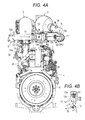
Fig. 4A is a back view of the engine shown inFig. 1 , andFig. 4B is a sectional view taken along line B-B inFig. 4A ; -
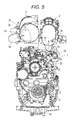
Fig. 5 is a front view of the engine shown inFig. 1 ; and -
Fig. 6 is a diagram for describing a principle of a slip joint portion used in the engine shown inFig. 1 . -
Figs. 1 to 6 are diagrams for describing a diesel engine according to an embodiment of the present invention. In this embodiment, a vertical type straight multicylinder diesel engine will be described. - A general outline of the engine is as follows.
- As shown in
Fig. 2 , a cylinder head (20) is assembled into an upper portion of a cylinder block (12), a cylinder head cover (7) is assembled into an upper portion of the cylinder head (20), a gear case (21) is assembled into a front portion of the cylinder block (12), a flywheel housing (6) is assembled into a rear end of the cylinder block (12), and an oil pan (23) is assembled into a lower portion of the cylinder block (12). - An intake manifold (24) is assembled into one of lateral sides of the cylinder head (20) as shown in
Fig. 2 , and an exhaust manifold (25) is assembled into the other lateral side as shown inFig. 3 . - As shown in
Figs. 1 to 5 , this engine includes an engine body (1), a DPF case (2) and an SCR catalyst case (3). - A DPF (4) is accommodated in the DPF case (2), and an SCR catalyst (5) is accommodated in the SCR catalyst case (3).
- The DPF case (2) and the SCR catalyst case (3) are mounted on the engine body (1).
- As shown in
Fig. 1 , a DOC (26) is accommodated in the DPF case (2) on an upstream side, and the DPF (4) is accommodated in the DPF case (2) on a downstream side. The DPF is an abbreviation of a diesel particulate filter, and the DOC is an abbreviation of a diesel oxidation catalyst. The SCR catalyst (5) is accommodated in the SCR catalyst case (3) on the upstream side, and an oxidation catalyst (27) is accommodated in the SCR catalyst case (3) on the downstream side, thereby preventing ammonia from slipping. The SCR is an abbreviation of selective catalytic reduction. - As shown in
Figs. 1 to 5 , the DPF case (2) is supported by the engine body (1) through an exhaust gas introducing pipe (2a), and the SCR catalyst case (3) is supported by the DPF case (2) through an exhaust gas relay pipe (8). - As shown in
Fig. 1 , the DPF case (2) and the SCR catalyst case (3) are oriented to a direction which extends along a crankshaft center axis (19). - As shown in
Figs. 1 ,4A and5 , if a width direction of the engine body (1) is defined as a lateral direction, the DPF case (2) and the SCR catalyst case (3) are arranged side by side and above the cylinder head cover (7). - As shown in
Fig. 3 , the exhaust gas introducing pipe (2a) of the DPF case (2) rearwardly curves and extends from a lower surface of a peripheral wall of a rear portion of the DPF case (2). A supercharger (22) is mounted on an upper portion of an exhaust manifold (25), an exhaust gas discharging pipe (22a) is provided on a rear portion of the supercharger (22), and the exhaust gas introducing pipe (2a) of the DPF case (2) is mounted on the exhaust gas discharging pipe (22a) of the supercharger (22). That is, the DPF case (2) is supported by the engine body (1) through the exhaust gas introducing pipe (2a) of the DPF case (2), the exhaust gas discharging pipe (22a) of a rear portion of the supercharger (22) and the supercharger (22). - According to this, the exhaust gas discharging pipe (22a) and the supercharger (22) are effectively utilized as support members of the DPF case (2) and the SCR catalyst case (3).
- As shown in
Fig. 1 , the exhaust gas relay pipe (8) is placed between an exhaust gas discharge pipe (2b) of the DPF case (2) and an exhaust gas introducing pipe (3a) of the SCR catalyst case (3). The exhaust gas relay pipe (8) includes a DPF-side exhaust gas relay pipe (12) and an SCR-side exhaust gas relay pipe (13). - As shown in
Fig. 1 , the DPF-side exhaust gas relay pipe (12) and the SCR-side exhaust gas relay pipe (13) respectively include straight pipe portions (12a) and (13a). As shown inFigs. 1 and3 , the straight pipe portion (12a) of the DPF-side exhaust gas relay pipe (12) is placed along a peripheral wall of the DPF case (2) in a direction which extends along a longitudinal direction of the DPF case (2). As shown inFigs. 1 and2 , the straight pipe portion (13a) of the SCR-side exhaust gas relay pipe (13) is placed along a peripheral wall of the SCR catalyst case (3) in a direction which extends along a longitudinal direction of the SCR catalyst case (3). - As shown in
Fig. 4B , exhaust gas (15) discharged from the DPF case (2) and urea aqueous solution (18) injected from a urea aqueous solution injector (16) are mixed with each other in the straight pipe portion (13a) of the SCR-side exhaust gas relay pipe (13). - As shown in
Figs. 1 to 5 , theDPF case 2 and theSCR catalyst case 3 are sandwiched between thestraight pipe portions gas relay pipe 12 and the SCR-side exhaustgas relay pipe 13 and thestraight pipe portions DPF case 2 and theSCR catalyst case 3. - As shown in
Fig. 1 , a direction of the crankshaft center axis (19) is defined as a longitudinal direction, the flywheel housing (6) is defined as existing on a rear side, and a width direction of the engine body (1) is defined as a lateral direction. Based on these definitions, the exhaust gas discharge pipe (2b) of the DPF case (2) rearwardly curves and extends from a peripheral wall of a front end of the DPF case (2) on a side opposite from the SCR catalyst case (3). - The exhaust gas introducing pipe (3a) of the SCR catalyst case (3) rearwardly curves and extends from a peripheral wall of a front end of the SCR catalyst case (3) on a side opposite from the DPF case (2).
- The DPF-side exhaust gas relay pipe (12) includes the straight pipe portion (12a) and a curved pipe portion (12b). The straight pipe portion (12a) straightly extends rearward from an extending end (2c) of the exhaust gas discharge pipe (2b) of the DPF case (2). The curved pipe portion (12b) laterally curves and extends from the extending end (12c) of the straight pipe portion (12a) toward the SCR catalyst case (3).
- The SCR-side exhaust gas relay pipe (13) includes the straight pipe portion (13a) and a curved pipe portion (13b). The curved pipe portion (13b) forwardly curves and extends from the extending end (12d) of the curved pipe portion (12b) of the DPF-side exhaust gas relay pipe (12) toward the exhaust gas introducing pipe (3a) of the SCR catalyst case (3). The straight pipe portion (13a) straightly extends forward from an extending end (13c) of the curved pipe portion (13b) toward the extending
end 3b of the exhaust gas introducing pipe (3a) of the SCR catalyst case (3). - As shown in
Fig. 1 , the curved pipe portion (12b) of the DPF-side exhaust gas relay pipe (12) includes a straight pipe-shaped extension portion (12e), and an inlet-side NOx sensor (33) is mounted on the extension portion (12e). As shown inFig. 2 , the urea aqueous solution injector (16) is mounted on the curved pipe portion (13b) of the SCR-side exhaust gas relay pipe (13). As shown inFig. 1 , the exhaust gas introducing pipe (3a) of the SCR catalyst case (3) includes a straight pipe-shaped extension portion (3c). An exhaust gas temperature sensor (35) is mounted on the exhaust gas introducing pipe (3a) of the SCR catalyst case (3). An outlet-side NOx sensor (34) is mounted on an exhaust gas introducing pipe (3d) of the SCR catalyst case (3). - As shown in
Fig. 1 , both ends of the SCR-side exhaust gas relay pipe (13) are provided with slip joint portions (17). As shown inFig. 6 , the slip joint portions (17) are fitted such that pipe portions (17a) and (17b) can expand, contract and slide in a longitudinal direction, and the pipe portions (17a) and (17b) are fixed by a fastening portion (17c) at predetermined expanding, contracting and sliding positions. The slip joint portions (17) are fitted such that the pipe portions (17a) and (17b) can rotate and slide in a peripheral direction, and the pipe portions (17a) and (17b) are fixed by the fastening portion (17c) at predetermined rotating and sliding positions. - The fastening portion (17c) fastens and fixes the pipe portions (17a) and (17b) by a fastening band. A space between the pipe portions (17a) and (17b) is sealed by a gasket (17d).
Claims (7)
- A diesel engine comprising an engine body 1, a DPF case 2 and an SCR catalyst case 3, in which a DPF 4 is accommodated in the DPF case 2 and an SCR catalyst 5 is accommodated in the SCR catalyst case 3, wherein
the DPF case 2 and the SCR catalyst case 3 are mounted on the engine body 1,
the DPF case 2 is supported by the engine body 1 through an exhaust gas introducing pipe 2a, and the SCR catalyst case 3 is supported by the DPF case 2 through an exhaust gas relay pipe 8. - The diesel engine according to claim 1, wherein
the DPF case 2 and the SCR catalyst case 3 are oriented to a direction which extends along a crankshaft center axis 19. - The diesel engine according to claim 2, wherein
when a width direction of the engine body 1 is defined as a lateral direction, the DPF case 2 and the SCR catalyst case 3 are arranged side by side and above the cylinder head cover 7. - The diesel engine according to claim 2 or 3, wherein
the exhaust gas relay pipe 8 is placed between an exhaust gas discharge pipe 2b of the DPF case 2 and an exhaust gas introducing pipe 3a of the SCR catalyst case 3, the diesel engine further comprises a DPF-side exhaust gas relay pipe 12 and an SCR-side exhaust gas relay pipe 13,
the DPF-side exhaust gas relay pipe 12 and the SCR-side exhaust gas relay pipe 13 respectively include straight pipe portions 12a and 13a, the straight pipe portion 12a of the DPF-side exhaust gas relay pipe 12 is placed along a peripheral wall of the DPF case 2 in a direction which extends along a longitudinal direction of the DPF case 2, and the straight pipe portion 13a of the SCR-side exhaust gas relay pipe 13 is placed along a peripheral wall of the SCR catalyst case 3 in a direction which extends along a longitudinal direction of the SCR catalyst case 3. - The diesel engine according to claim 4, wherein
when a width direction of the engine body 1 is defined as a lateral direction,
exhaust gas 15 discharged from the DPF case 2 and urea aqueous solution 18 injected from a urea aqueous solution injector 16 are mixed with each other in the straight pipe portion 13a of the SCR-side exhaust gas relay pipe 13, and
the DPF case 2 and the SCR catalyst case 3 are sandwiched between the straight pipe portions 12a and 13a of the DPF-side exhaust gas relay pipe 12 and the SCR-side exhaust gas relay pipe 13 and the straight pipe portions 12a and 13a are placed lateral to the DPF case 2 and the SCR catalyst case 3. - The diesel engine according to claim 5, wherein
when a direction of the crankshaft center axis 19 is defined as a longitudinal direction and the flywheel housing 6 is defined as existing on a rear side,
the exhaust gas discharge pipe 2b of the DPF case 2 rearwardly curves and extends from a peripheral wall of a front end of the DPF case 2 on a side opposite from the SCR catalyst case 3,
the exhaust gas introducing pipe 3a of the SCR catalyst case 3 rearwardly curves and extends from a peripheral wall of a front end of the SCR catalyst case 3 on a side opposite from the DPF case 2,
the DPF-side exhaust gas relay pipe 12 comprises the straight pipe portion 12a and a curved pipe portion 12b, the straight pipe portion 12a straightly extends rearward from an extending end 2c of the exhaust gas discharge pipe 2b of the DPF case 2, the curved pipe portion 12b laterally curves and extends from the extending end 12c of the straight pipe portion 12a toward the SCR catalyst case 3,
the SCR-side exhaust gas relay pipe 13 comprises the straight pipe portion 13a and a curved pipe portion 13b, the curved pipe portion 13b forwardly curves and extends from the extending end 12d of the curved pipe portion 12b of the DPF-side exhaust gas relay pipe 12 toward the exhaust gas introducing pipe 3a of the SCR catalyst case 3, and the straight pipe portion 13a straightly extends forward from an extending end 13c of the curved pipe portion 13b toward the extending end 3b of the exhaust gas introducing pipe 3a of the SCR catalyst case 3. - The diesel engine according to any one of claims 4 to 6, wherein
both ends of the SCR-side exhaust gas relay pipe 13 are provided with slip joint portions 17, each of the slip joint portions 17 is fitted such that pipe portions 17a and 17b can expand, contract and slide in a longitudinal direction thereof, and the pipe portions 17a and 17b are fixed by a fastening portion 17c at predetermined expanding, contracting and sliding positions.
Applications Claiming Priority (1)
| Application Number | Priority Date | Filing Date | Title |
|---|---|---|---|
| JP2013268348A JP6087804B2 (en) | 2013-12-26 | 2013-12-26 | diesel engine |
Publications (2)
| Publication Number | Publication Date |
|---|---|
| EP2889460A1 true EP2889460A1 (en) | 2015-07-01 |
| EP2889460B1 EP2889460B1 (en) | 2017-03-29 |
Family
ID=51298670
Family Applications (1)
| Application Number | Title | Priority Date | Filing Date |
|---|---|---|---|
| EP14180589.5A Active EP2889460B1 (en) | 2013-12-26 | 2014-08-11 | Diesel engine |
Country Status (3)
| Country | Link |
|---|---|
| US (1) | US9441514B2 (en) |
| EP (1) | EP2889460B1 (en) |
| JP (1) | JP6087804B2 (en) |
Cited By (3)
| Publication number | Priority date | Publication date | Assignee | Title |
|---|---|---|---|---|
| EP3324017A1 (en) * | 2016-11-21 | 2018-05-23 | Perkins Engines Company Limited | Aftertreatment assembly tolerance compensation scheme |
| DE102017100787A1 (en) | 2017-01-17 | 2018-07-19 | Volkswagen Aktiengesellschaft | Exhaust Aftertreatment Assembly and Method of Making Such Exhaust Aftertreatment Assembly |
| WO2019019725A1 (en) * | 2017-07-27 | 2019-01-31 | 天纳克(苏州)排放系统有限公司 | Engine exhaust after-treatment mixing device, after-treatment device comprising same, and application thereof |
Families Citing this family (7)
| Publication number | Priority date | Publication date | Assignee | Title |
|---|---|---|---|---|
| JP6682972B2 (en) * | 2016-04-14 | 2020-04-15 | いすゞ自動車株式会社 | Exhaust gas purification device for internal combustion engine |
| JP6612178B2 (en) | 2016-05-27 | 2019-11-27 | 株式会社クボタ | Working machine |
| EP3372798B1 (en) * | 2017-03-08 | 2020-03-04 | Perkins Engines Company Limited | A compact selective catalytic reduction system |
| JP6979593B2 (en) * | 2019-03-22 | 2021-12-15 | ヤンマーパワーテクノロジー株式会社 | engine |
| JP7513480B2 (en) * | 2020-09-30 | 2024-07-09 | ヤンマーホールディングス株式会社 | diesel engine |
| US12215612B2 (en) * | 2020-12-03 | 2025-02-04 | Transportation Ip Holdings, Llc | System and method for a cab-mounted muffler assembly |
| JP7506787B2 (en) * | 2021-10-26 | 2024-06-26 | ヤンマーパワーテクノロジー株式会社 | engine |
Citations (6)
| Publication number | Priority date | Publication date | Assignee | Title |
|---|---|---|---|---|
| EP0226088A1 (en) * | 1985-12-03 | 1987-06-24 | Witzenmann GmbH Metallschlauch-Fabrik Pforzheim | Pipe connection, particularly for internal combustion engines |
| EP1026375A2 (en) * | 1999-02-05 | 2000-08-09 | Witzenmann GmbH Metallschlauch-Fabrik Pforzheim | Pipe member for exhaust conduits in motor vehicles |
| US20100031644A1 (en) * | 2008-08-07 | 2010-02-11 | Caterpillar Inc. | Mounting assembly for emissions control system |
| US20100186381A1 (en) * | 2009-01-26 | 2010-07-29 | Caterpillar Inc | Exhaust system thermal enclosure |
| JP2011032946A (en) | 2009-08-03 | 2011-02-17 | Mitsubishi Fuso Truck & Bus Corp | Exhaust emission control device of internal combustion engine |
| EP2518290A1 (en) * | 2011-04-28 | 2012-10-31 | Caterpillar INC. | Exhaust gas aftertreatment support assembly |
Family Cites Families (18)
| Publication number | Priority date | Publication date | Assignee | Title |
|---|---|---|---|---|
| JPH051529A (en) * | 1991-06-27 | 1993-01-08 | Toyota Motor Corp | Exhaust device for internal combustion engine |
| GB2428739B (en) * | 2005-08-05 | 2010-03-31 | Ford Global Tech Llc | An exhaust manifold for an internal combustion engine |
| JP4286887B2 (en) * | 2007-09-28 | 2009-07-01 | 日産ディーゼル工業株式会社 | Exhaust purification equipment |
| JP4995689B2 (en) * | 2007-10-26 | 2012-08-08 | 日野自動車株式会社 | Exhaust purification device |
| US20100186394A1 (en) * | 2009-01-26 | 2010-07-29 | Caterpillar Inc. | Exhaust gas after treatment assembly |
| US20110079003A1 (en) * | 2009-10-05 | 2011-04-07 | Caterpillar Inc. | Reductant nozzle indentation mount |
| US8460610B2 (en) * | 2009-12-22 | 2013-06-11 | Caterpillar Inc. | Canister aftertreatment module |
| JP2012215022A (en) * | 2011-03-31 | 2012-11-08 | Komatsu Ltd | Engine unit |
| JP5663424B2 (en) * | 2011-07-20 | 2015-02-04 | 株式会社クボタ | Exhaust treatment device manufacturing method |
| JP2013104394A (en) * | 2011-11-16 | 2013-05-30 | Hino Motors Ltd | Exhaust emission control device |
| KR20140116083A (en) * | 2012-01-06 | 2014-10-01 | 볼보 컨스트럭션 이큅먼트 에이비 | Exhaust gas reduction device for heavy equipment |
| DE102012000591A1 (en) * | 2012-01-14 | 2013-07-18 | Daimler Ag | Engine block assembly with an exhaust system |
| DE112013000116B4 (en) * | 2012-10-16 | 2015-04-23 | Komatsu Ltd. | hydraulic excavators |
| JP5449517B1 (en) * | 2012-12-20 | 2014-03-19 | 株式会社小松製作所 | Work vehicle |
| US8919486B2 (en) * | 2013-02-15 | 2014-12-30 | Komatsu Ltd. | Hydraulic excavator |
| US8936128B2 (en) * | 2013-02-22 | 2015-01-20 | Komatsu Ltd. | Engine room of a wheel loader |
| DE112013000161C5 (en) * | 2013-03-15 | 2023-03-16 | Komatsu Ltd. | Exhaust aftertreatment unit and a construction vehicle containing it |
| CN104471153B (en) * | 2013-03-29 | 2016-02-10 | 株式会社小松制作所 | Bulldozer |
-
2013
- 2013-12-26 JP JP2013268348A patent/JP6087804B2/en active Active
-
2014
- 2014-08-11 EP EP14180589.5A patent/EP2889460B1/en active Active
- 2014-08-19 US US14/462,663 patent/US9441514B2/en active Active
Patent Citations (6)
| Publication number | Priority date | Publication date | Assignee | Title |
|---|---|---|---|---|
| EP0226088A1 (en) * | 1985-12-03 | 1987-06-24 | Witzenmann GmbH Metallschlauch-Fabrik Pforzheim | Pipe connection, particularly for internal combustion engines |
| EP1026375A2 (en) * | 1999-02-05 | 2000-08-09 | Witzenmann GmbH Metallschlauch-Fabrik Pforzheim | Pipe member for exhaust conduits in motor vehicles |
| US20100031644A1 (en) * | 2008-08-07 | 2010-02-11 | Caterpillar Inc. | Mounting assembly for emissions control system |
| US20100186381A1 (en) * | 2009-01-26 | 2010-07-29 | Caterpillar Inc | Exhaust system thermal enclosure |
| JP2011032946A (en) | 2009-08-03 | 2011-02-17 | Mitsubishi Fuso Truck & Bus Corp | Exhaust emission control device of internal combustion engine |
| EP2518290A1 (en) * | 2011-04-28 | 2012-10-31 | Caterpillar INC. | Exhaust gas aftertreatment support assembly |
Cited By (4)
| Publication number | Priority date | Publication date | Assignee | Title |
|---|---|---|---|---|
| EP3324017A1 (en) * | 2016-11-21 | 2018-05-23 | Perkins Engines Company Limited | Aftertreatment assembly tolerance compensation scheme |
| US10247081B2 (en) | 2016-11-21 | 2019-04-02 | Perkins Engines Company Limited | Aftertreatment assembly tolerance compensation scheme |
| DE102017100787A1 (en) | 2017-01-17 | 2018-07-19 | Volkswagen Aktiengesellschaft | Exhaust Aftertreatment Assembly and Method of Making Such Exhaust Aftertreatment Assembly |
| WO2019019725A1 (en) * | 2017-07-27 | 2019-01-31 | 天纳克(苏州)排放系统有限公司 | Engine exhaust after-treatment mixing device, after-treatment device comprising same, and application thereof |
Also Published As
| Publication number | Publication date |
|---|---|
| EP2889460B1 (en) | 2017-03-29 |
| US9441514B2 (en) | 2016-09-13 |
| JP6087804B2 (en) | 2017-03-01 |
| JP2015124642A (en) | 2015-07-06 |
| US20150184566A1 (en) | 2015-07-02 |
Similar Documents
| Publication | Publication Date | Title |
|---|---|---|
| EP2889460B1 (en) | Diesel engine | |
| EP2853704B1 (en) | Diesel engine | |
| CN104040130B (en) | Emission-control equipment | |
| EP2554816A3 (en) | NH3 emissions management in a nox reduction system | |
| EP2841727B1 (en) | Aftertreatment module with sensor mounting arrangement | |
| EP2878781B1 (en) | Cooling water circulation device | |
| JP2009167806A (en) | Exhaust gas purification device for internal combustion engine | |
| EP2282027A8 (en) | Heating exhaust gas for diesel particulate filter regeneration | |
| WO2007098514A3 (en) | Exhaust system for an internal combustion engine | |
| EP2126305A4 (en) | EXHAUST GAS POST-TREATMENT SYSTEM (EATS) | |
| US20160326937A1 (en) | Plenum chamber for exhaust system | |
| US20170114698A1 (en) | Exhaust-gas module for an internal combustion engine | |
| GB2500059A (en) | Mixer for an exhaust gas after-treatment system | |
| US9482133B2 (en) | Exhaust emission control system of internal combustion engine | |
| EP3222830B1 (en) | Industrial vehicle | |
| FR3021996B1 (en) | DEVICE FOR HEATING A LIQUID, IN PARTICULAR A REDUCING AGENT FOR REDUCING THE EXHAUST GASES EMITTED BY A MOTOR VEHICLE INTERNAL COMBUSTION ENGINE | |
| EP3073079B1 (en) | Engine exhaust aftertreatment device | |
| JP6051154B2 (en) | diesel engine | |
| JP6391405B2 (en) | Exhaust gas purification device | |
| MX2007002474A (en) | Structure for filtering exhaust gases of an internal combustion engine, and associated exhaust line. | |
| JP6087778B2 (en) | diesel engine | |
| JP6391406B2 (en) | Exhaust gas purification device | |
| FI20175264A7 (en) | Exhaust gas aftertreatment system, internal combustion engine and method for operating the same | |
| EP2309103A3 (en) | Exhaust gas device for an internal combustion engine | |
| WO2014040701A8 (en) | Scr module |
Legal Events
| Date | Code | Title | Description |
|---|---|---|---|
| PUAI | Public reference made under article 153(3) epc to a published international application that has entered the european phase |
Free format text: ORIGINAL CODE: 0009012 |
|
| 17P | Request for examination filed |
Effective date: 20140811 |
|
| AK | Designated contracting states |
Kind code of ref document: A1 Designated state(s): AL AT BE BG CH CY CZ DE DK EE ES FI FR GB GR HR HU IE IS IT LI LT LU LV MC MK MT NL NO PL PT RO RS SE SI SK SM TR |
|
| AX | Request for extension of the european patent |
Extension state: BA ME |
|
| R17P | Request for examination filed (corrected) |
Effective date: 20150828 |
|
| RBV | Designated contracting states (corrected) |
Designated state(s): AL AT BE BG CH CY CZ DE DK EE ES FI FR GB GR HR HU IE IS IT LI LT LU LV MC MK MT NL NO PL PT RO RS SE SI SK SM TR |
|
| GRAP | Despatch of communication of intention to grant a patent |
Free format text: ORIGINAL CODE: EPIDOSNIGR1 |
|
| INTG | Intention to grant announced |
Effective date: 20161116 |
|
| GRAS | Grant fee paid |
Free format text: ORIGINAL CODE: EPIDOSNIGR3 |
|
| GRAA | (expected) grant |
Free format text: ORIGINAL CODE: 0009210 |
|
| AK | Designated contracting states |
Kind code of ref document: B1 Designated state(s): AL AT BE BG CH CY CZ DE DK EE ES FI FR GB GR HR HU IE IS IT LI LT LU LV MC MK MT NL NO PL PT RO RS SE SI SK SM TR |
|
| REG | Reference to a national code |
Ref country code: GB Ref legal event code: FG4D |
|
| REG | Reference to a national code |
Ref country code: CH Ref legal event code: EP |
|
| REG | Reference to a national code |
Ref country code: AT Ref legal event code: REF Ref document number: 879991 Country of ref document: AT Kind code of ref document: T Effective date: 20170415 |
|
| REG | Reference to a national code |
Ref country code: IE Ref legal event code: FG4D |
|
| REG | Reference to a national code |
Ref country code: DE Ref legal event code: R096 Ref document number: 602014008013 Country of ref document: DE |
|
| REG | Reference to a national code |
Ref country code: FR Ref legal event code: PLFP Year of fee payment: 4 |
|
| PG25 | Lapsed in a contracting state [announced via postgrant information from national office to epo] |
Ref country code: GR Free format text: LAPSE BECAUSE OF FAILURE TO SUBMIT A TRANSLATION OF THE DESCRIPTION OR TO PAY THE FEE WITHIN THE PRESCRIBED TIME-LIMIT Effective date: 20170630 Ref country code: LT Free format text: LAPSE BECAUSE OF FAILURE TO SUBMIT A TRANSLATION OF THE DESCRIPTION OR TO PAY THE FEE WITHIN THE PRESCRIBED TIME-LIMIT Effective date: 20170329 Ref country code: NO Free format text: LAPSE BECAUSE OF FAILURE TO SUBMIT A TRANSLATION OF THE DESCRIPTION OR TO PAY THE FEE WITHIN THE PRESCRIBED TIME-LIMIT Effective date: 20170629 Ref country code: FI Free format text: LAPSE BECAUSE OF FAILURE TO SUBMIT A TRANSLATION OF THE DESCRIPTION OR TO PAY THE FEE WITHIN THE PRESCRIBED TIME-LIMIT Effective date: 20170329 Ref country code: HR Free format text: LAPSE BECAUSE OF FAILURE TO SUBMIT A TRANSLATION OF THE DESCRIPTION OR TO PAY THE FEE WITHIN THE PRESCRIBED TIME-LIMIT Effective date: 20170329 |
|
| REG | Reference to a national code |
Ref country code: NL Ref legal event code: MP Effective date: 20170329 |
|
| REG | Reference to a national code |
Ref country code: AT Ref legal event code: MK05 Ref document number: 879991 Country of ref document: AT Kind code of ref document: T Effective date: 20170329 |
|
| PG25 | Lapsed in a contracting state [announced via postgrant information from national office to epo] |
Ref country code: RS Free format text: LAPSE BECAUSE OF FAILURE TO SUBMIT A TRANSLATION OF THE DESCRIPTION OR TO PAY THE FEE WITHIN THE PRESCRIBED TIME-LIMIT Effective date: 20170329 Ref country code: LV Free format text: LAPSE BECAUSE OF FAILURE TO SUBMIT A TRANSLATION OF THE DESCRIPTION OR TO PAY THE FEE WITHIN THE PRESCRIBED TIME-LIMIT Effective date: 20170329 Ref country code: BG Free format text: LAPSE BECAUSE OF FAILURE TO SUBMIT A TRANSLATION OF THE DESCRIPTION OR TO PAY THE FEE WITHIN THE PRESCRIBED TIME-LIMIT Effective date: 20170629 Ref country code: SE Free format text: LAPSE BECAUSE OF FAILURE TO SUBMIT A TRANSLATION OF THE DESCRIPTION OR TO PAY THE FEE WITHIN THE PRESCRIBED TIME-LIMIT Effective date: 20170329 |
|
| PG25 | Lapsed in a contracting state [announced via postgrant information from national office to epo] |
Ref country code: NL Free format text: LAPSE BECAUSE OF FAILURE TO SUBMIT A TRANSLATION OF THE DESCRIPTION OR TO PAY THE FEE WITHIN THE PRESCRIBED TIME-LIMIT Effective date: 20170329 |
|
| PG25 | Lapsed in a contracting state [announced via postgrant information from national office to epo] |
Ref country code: SK Free format text: LAPSE BECAUSE OF FAILURE TO SUBMIT A TRANSLATION OF THE DESCRIPTION OR TO PAY THE FEE WITHIN THE PRESCRIBED TIME-LIMIT Effective date: 20170329 Ref country code: ES Free format text: LAPSE BECAUSE OF FAILURE TO SUBMIT A TRANSLATION OF THE DESCRIPTION OR TO PAY THE FEE WITHIN THE PRESCRIBED TIME-LIMIT Effective date: 20170329 Ref country code: EE Free format text: LAPSE BECAUSE OF FAILURE TO SUBMIT A TRANSLATION OF THE DESCRIPTION OR TO PAY THE FEE WITHIN THE PRESCRIBED TIME-LIMIT Effective date: 20170329 Ref country code: RO Free format text: LAPSE BECAUSE OF FAILURE TO SUBMIT A TRANSLATION OF THE DESCRIPTION OR TO PAY THE FEE WITHIN THE PRESCRIBED TIME-LIMIT Effective date: 20170329 Ref country code: AT Free format text: LAPSE BECAUSE OF FAILURE TO SUBMIT A TRANSLATION OF THE DESCRIPTION OR TO PAY THE FEE WITHIN THE PRESCRIBED TIME-LIMIT Effective date: 20170329 Ref country code: CZ Free format text: LAPSE BECAUSE OF FAILURE TO SUBMIT A TRANSLATION OF THE DESCRIPTION OR TO PAY THE FEE WITHIN THE PRESCRIBED TIME-LIMIT Effective date: 20170329 Ref country code: IT Free format text: LAPSE BECAUSE OF FAILURE TO SUBMIT A TRANSLATION OF THE DESCRIPTION OR TO PAY THE FEE WITHIN THE PRESCRIBED TIME-LIMIT Effective date: 20170329 |
|
| PG25 | Lapsed in a contracting state [announced via postgrant information from national office to epo] |
Ref country code: PT Free format text: LAPSE BECAUSE OF FAILURE TO SUBMIT A TRANSLATION OF THE DESCRIPTION OR TO PAY THE FEE WITHIN THE PRESCRIBED TIME-LIMIT Effective date: 20170731 Ref country code: PL Free format text: LAPSE BECAUSE OF FAILURE TO SUBMIT A TRANSLATION OF THE DESCRIPTION OR TO PAY THE FEE WITHIN THE PRESCRIBED TIME-LIMIT Effective date: 20170329 Ref country code: SM Free format text: LAPSE BECAUSE OF FAILURE TO SUBMIT A TRANSLATION OF THE DESCRIPTION OR TO PAY THE FEE WITHIN THE PRESCRIBED TIME-LIMIT Effective date: 20170329 Ref country code: IS Free format text: LAPSE BECAUSE OF FAILURE TO SUBMIT A TRANSLATION OF THE DESCRIPTION OR TO PAY THE FEE WITHIN THE PRESCRIBED TIME-LIMIT Effective date: 20170729 |
|
| REG | Reference to a national code |
Ref country code: DE Ref legal event code: R097 Ref document number: 602014008013 Country of ref document: DE |
|
| PG25 | Lapsed in a contracting state [announced via postgrant information from national office to epo] |
Ref country code: DK Free format text: LAPSE BECAUSE OF FAILURE TO SUBMIT A TRANSLATION OF THE DESCRIPTION OR TO PAY THE FEE WITHIN THE PRESCRIBED TIME-LIMIT Effective date: 20170329 |
|
| PLBE | No opposition filed within time limit |
Free format text: ORIGINAL CODE: 0009261 |
|
| STAA | Information on the status of an ep patent application or granted ep patent |
Free format text: STATUS: NO OPPOSITION FILED WITHIN TIME LIMIT |
|
| 26N | No opposition filed |
Effective date: 20180103 |
|
| REG | Reference to a national code |
Ref country code: CH Ref legal event code: PL |
|
| PG25 | Lapsed in a contracting state [announced via postgrant information from national office to epo] |
Ref country code: MC Free format text: LAPSE BECAUSE OF FAILURE TO SUBMIT A TRANSLATION OF THE DESCRIPTION OR TO PAY THE FEE WITHIN THE PRESCRIBED TIME-LIMIT Effective date: 20170329 |
|
| PG25 | Lapsed in a contracting state [announced via postgrant information from national office to epo] |
Ref country code: CH Free format text: LAPSE BECAUSE OF NON-PAYMENT OF DUE FEES Effective date: 20170831 Ref country code: LI Free format text: LAPSE BECAUSE OF NON-PAYMENT OF DUE FEES Effective date: 20170831 |
|
| REG | Reference to a national code |
Ref country code: IE Ref legal event code: MM4A |
|
| PG25 | Lapsed in a contracting state [announced via postgrant information from national office to epo] |
Ref country code: SI Free format text: LAPSE BECAUSE OF FAILURE TO SUBMIT A TRANSLATION OF THE DESCRIPTION OR TO PAY THE FEE WITHIN THE PRESCRIBED TIME-LIMIT Effective date: 20170329 |
|
| REG | Reference to a national code |
Ref country code: BE Ref legal event code: MM Effective date: 20170831 |
|
| PG25 | Lapsed in a contracting state [announced via postgrant information from national office to epo] |
Ref country code: LU Free format text: LAPSE BECAUSE OF NON-PAYMENT OF DUE FEES Effective date: 20170811 |
|
| REG | Reference to a national code |
Ref country code: FR Ref legal event code: PLFP Year of fee payment: 5 |
|
| PG25 | Lapsed in a contracting state [announced via postgrant information from national office to epo] |
Ref country code: IE Free format text: LAPSE BECAUSE OF NON-PAYMENT OF DUE FEES Effective date: 20170811 |
|
| PG25 | Lapsed in a contracting state [announced via postgrant information from national office to epo] |
Ref country code: BE Free format text: LAPSE BECAUSE OF NON-PAYMENT OF DUE FEES Effective date: 20170831 |
|
| PG25 | Lapsed in a contracting state [announced via postgrant information from national office to epo] |
Ref country code: MT Free format text: LAPSE BECAUSE OF NON-PAYMENT OF DUE FEES Effective date: 20170811 |
|
| PG25 | Lapsed in a contracting state [announced via postgrant information from national office to epo] |
Ref country code: HU Free format text: LAPSE BECAUSE OF FAILURE TO SUBMIT A TRANSLATION OF THE DESCRIPTION OR TO PAY THE FEE WITHIN THE PRESCRIBED TIME-LIMIT; INVALID AB INITIO Effective date: 20140811 |
|
| PG25 | Lapsed in a contracting state [announced via postgrant information from national office to epo] |
Ref country code: CY Free format text: LAPSE BECAUSE OF FAILURE TO SUBMIT A TRANSLATION OF THE DESCRIPTION OR TO PAY THE FEE WITHIN THE PRESCRIBED TIME-LIMIT Effective date: 20170329 |
|
| PG25 | Lapsed in a contracting state [announced via postgrant information from national office to epo] |
Ref country code: MK Free format text: LAPSE BECAUSE OF FAILURE TO SUBMIT A TRANSLATION OF THE DESCRIPTION OR TO PAY THE FEE WITHIN THE PRESCRIBED TIME-LIMIT Effective date: 20170329 |
|
| PG25 | Lapsed in a contracting state [announced via postgrant information from national office to epo] |
Ref country code: TR Free format text: LAPSE BECAUSE OF FAILURE TO SUBMIT A TRANSLATION OF THE DESCRIPTION OR TO PAY THE FEE WITHIN THE PRESCRIBED TIME-LIMIT Effective date: 20170329 |
|
| PG25 | Lapsed in a contracting state [announced via postgrant information from national office to epo] |
Ref country code: AL Free format text: LAPSE BECAUSE OF FAILURE TO SUBMIT A TRANSLATION OF THE DESCRIPTION OR TO PAY THE FEE WITHIN THE PRESCRIBED TIME-LIMIT Effective date: 20170329 |
|
| PGFP | Annual fee paid to national office [announced via postgrant information from national office to epo] |
Ref country code: DE Payment date: 20250702 Year of fee payment: 12 |
|
| PGFP | Annual fee paid to national office [announced via postgrant information from national office to epo] |
Ref country code: GB Payment date: 20250703 Year of fee payment: 12 |
|
| PGFP | Annual fee paid to national office [announced via postgrant information from national office to epo] |
Ref country code: FR Payment date: 20250703 Year of fee payment: 12 |