EP2889425B1 - Washing machine with bottom cover - Google Patents
Washing machine with bottom cover Download PDFInfo
- Publication number
- EP2889425B1 EP2889425B1 EP14199543.1A EP14199543A EP2889425B1 EP 2889425 B1 EP2889425 B1 EP 2889425B1 EP 14199543 A EP14199543 A EP 14199543A EP 2889425 B1 EP2889425 B1 EP 2889425B1
- Authority
- EP
- European Patent Office
- Prior art keywords
- wash
- washing machine
- bottom cover
- wash water
- water reservoir
- Prior art date
- Legal status (The legal status is an assumption and is not a legal conclusion. Google has not performed a legal analysis and makes no representation as to the accuracy of the status listed.)
- Active
Links
- 238000005406 washing Methods 0.000 title claims description 51
- XLYOFNOQVPJJNP-UHFFFAOYSA-N water Substances O XLYOFNOQVPJJNP-UHFFFAOYSA-N 0.000 claims description 73
- 239000007788 liquid Substances 0.000 claims description 37
- 239000002351 wastewater Substances 0.000 claims description 17
- 238000011010 flushing procedure Methods 0.000 claims description 3
- 239000003599 detergent Substances 0.000 description 11
- 230000000295 complement effect Effects 0.000 description 5
- 239000013505 freshwater Substances 0.000 description 4
- 238000011161 development Methods 0.000 description 3
- 230000018109 developmental process Effects 0.000 description 3
- 238000011084 recovery Methods 0.000 description 3
- 238000012546 transfer Methods 0.000 description 3
- 238000010586 diagram Methods 0.000 description 2
- 238000000034 method Methods 0.000 description 2
- 238000000465 moulding Methods 0.000 description 2
- 210000002445 nipple Anatomy 0.000 description 2
- 230000002787 reinforcement Effects 0.000 description 2
- 238000003466 welding Methods 0.000 description 2
- 230000005540 biological transmission Effects 0.000 description 1
- 230000000903 blocking effect Effects 0.000 description 1
- 238000000071 blow moulding Methods 0.000 description 1
- 238000004891 communication Methods 0.000 description 1
- 230000001419 dependent effect Effects 0.000 description 1
- 238000013461 design Methods 0.000 description 1
- 238000001514 detection method Methods 0.000 description 1
- 239000012530 fluid Substances 0.000 description 1
- 238000001746 injection moulding Methods 0.000 description 1
- 238000009434 installation Methods 0.000 description 1
- 230000010354 integration Effects 0.000 description 1
- 239000000463 material Substances 0.000 description 1
- 239000002184 metal Substances 0.000 description 1
- 238000005086 pumping Methods 0.000 description 1
- 238000004064 recycling Methods 0.000 description 1
- 230000008439 repair process Effects 0.000 description 1
- 238000002791 soaking Methods 0.000 description 1
- 239000011800 void material Substances 0.000 description 1
Images


Classifications
-
- D—TEXTILES; PAPER
- D06—TREATMENT OF TEXTILES OR THE LIKE; LAUNDERING; FLEXIBLE MATERIALS NOT OTHERWISE PROVIDED FOR
- D06F—LAUNDERING, DRYING, IRONING, PRESSING OR FOLDING TEXTILE ARTICLES
- D06F21/00—Washing machines with receptacles, e.g. perforated, having a rotary movement, e.g. oscillatory movement
- D06F21/02—Washing machines with receptacles, e.g. perforated, having a rotary movement, e.g. oscillatory movement about a horizontal axis
- D06F21/04—Washing machines with receptacles, e.g. perforated, having a rotary movement, e.g. oscillatory movement about a horizontal axis within an enclosing receptacle
-
- D—TEXTILES; PAPER
- D06—TREATMENT OF TEXTILES OR THE LIKE; LAUNDERING; FLEXIBLE MATERIALS NOT OTHERWISE PROVIDED FOR
- D06F—LAUNDERING, DRYING, IRONING, PRESSING OR FOLDING TEXTILE ARTICLES
- D06F39/00—Details of washing machines not specific to a single type of machines covered by groups D06F9/00 - D06F27/00
- D06F39/08—Liquid supply or discharge arrangements
- D06F39/083—Liquid discharge or recirculation arrangements
-
- D—TEXTILES; PAPER
- D06—TREATMENT OF TEXTILES OR THE LIKE; LAUNDERING; FLEXIBLE MATERIALS NOT OTHERWISE PROVIDED FOR
- D06F—LAUNDERING, DRYING, IRONING, PRESSING OR FOLDING TEXTILE ARTICLES
- D06F39/00—Details of washing machines not specific to a single type of machines covered by groups D06F9/00 - D06F27/00
- D06F39/12—Casings; Tubs
-
- D—TEXTILES; PAPER
- D06—TREATMENT OF TEXTILES OR THE LIKE; LAUNDERING; FLEXIBLE MATERIALS NOT OTHERWISE PROVIDED FOR
- D06F—LAUNDERING, DRYING, IRONING, PRESSING OR FOLDING TEXTILE ARTICLES
- D06F39/00—Details of washing machines not specific to a single type of machines covered by groups D06F9/00 - D06F27/00
- D06F39/08—Liquid supply or discharge arrangements
- D06F39/081—Safety arrangements for preventing water damage
-
- D—TEXTILES; PAPER
- D06—TREATMENT OF TEXTILES OR THE LIKE; LAUNDERING; FLEXIBLE MATERIALS NOT OTHERWISE PROVIDED FOR
- D06F—LAUNDERING, DRYING, IRONING, PRESSING OR FOLDING TEXTILE ARTICLES
- D06F39/00—Details of washing machines not specific to a single type of machines covered by groups D06F9/00 - D06F27/00
- D06F39/08—Liquid supply or discharge arrangements
- D06F39/083—Liquid discharge or recirculation arrangements
- D06F39/085—Arrangements or adaptations of pumps
Definitions
- the present invention relates to the technical field of washing machines and, in particular, to a washing machine comprising a housing with a bottom cover, and a hydraulic flushing system, comprising a first pump motor and a second pump motor and at least one wash liquid duct.
- a modern washing machine comprises a hydraulic system with wash water ducts and at least one pump to evacuate the water from tub to the outside through flexible hoses once the laundry has been cleaned or rinsed.
- Many washing machines also incorporate an "Aquastop" tray or wastewater collection tray having the shape of and constituting a bottom cover that is fixed to the frame, thereby defining a lower limit of a space inside the frame wherein the tub may be contained, possibly in a swinging fashion as in a laundry washer.
- an electrical wastewater detector device with a float element that, when the wastewater exceeds a certain level, sends a signal to a shutoff valve arranged in the water supply hose that is connected to the external tap to stop the supply of water to the washing machine.
- Washing machines with this type of hydraulic system are prone to a number of drawbacks when the utilizing the interior space, the access to elements such as the pump used for draining water from the wash tub, installation of the hydraulic system hoses in the factory, and access to the pump and various of these when repairs made.
- Document EP 2 447 405 A1 discloses a washing machine comprising a recovery tank separate from the wash tank and suitable for containing a portion of recovered liquid, recycling means that introduce, during one of the steps of the washing program, the portion of recovered liquid from the recovery tank into the wash tank, and recovering means that, after at least one wash cycle step, convey a potion of liquid used during the wash cycle from the wash tank into the recovery tank.
- a washing machine comprising a housing with a bottom cover, and a hydraulic flushing system, comprising a first pump motor and a second pump motor and at least one wash liquid duct. Further, at least a part of at least one hydraulic element selected from the at least one wash liquid duct and the first and the second pump motor is integrated into the bottom cover.
- the integration of the hydraulic elements in the bottom cover enables a reduction in assembly time for the hydraulic elements of the hydraulic washing system, such as pumps and hoses, since the positioning and interconnection of same are predetermined by the location of these hydraulics elements in the bottom cover. It is also possible to achieve a better utilization of the available space in the washing machine interior with which one can opt for a greater compactness and/or better arrangement of the hydraulic elements, compared to conventional washing machines. Moreover, the invention also provides design flexibility to be able to arrange the pump or pumps or water circulation duct connection or connections conveniently, for example, by reducing the risk of incorrect assembly or allowing easy and rapid accessibility for assembly/disassembly.
- At least part of the bottom cover can be manufactured by injection molding separately from a top and a bottom, then joined later, preferably by welding, most preferably ultrasonic welding.
- the bottom cover can be manufactured by blow molding.
- At least a portion of at least one wash liquid duct is integrated into the bottom cover.
- At least one of the pumps arranged in the bottom cover comprises a part of the pump motor housing that is at least partially integrated into the bottom cover, which reduces the transmission of noise and vibrations generated by the pump or pumps.
- the bottom cover also comprises a wastewater collection tray, which is preferably integrated into the bottom cover, and which can be formed in the bottom cover during the molding process of the same.
- the washing machine comprises a frame and the bottom cover closes a bottom of the frame and, preferably, is at least partially detachable.
- This embodiment of the system allows access to the interior of the appliance, particularly to the pump or pumps, without dismantling the oscillating group (tub, drum, and drive motor), which is especially useful in frames formed into a U (closed in the rear), even if the appliance must be leaned back.
- any releasable fixing method such as a clipping ("press fit") or screwing, can be used.
- an airtight fixing is provided when the bottom cover incorporates an Aquastop tray.
- the bottom cover can be hinged, and the bottom cover can be a one-piece cover or a two-piece cover comprising an exterior framework that is fixed to the bottom of the frame and a closing plate that is connected hingeably to the exterior framework.
- the bottom cover When the bottom cover is a one-piece cover, it can comprise a hinge by means of being articulated to the bottom of the washing machine frame or to an element arranged at the bottom of the frame.
- the bottom cover is a two-piece cover
- the exterior framework is firmly joined to the bottom of the frame
- the closing plate is articulated to the outer frame or to another element arranged on the bottom of the washing machine by means of a hinge, such that the closing plate is capable of swinging with respect to the exterior framework.
- the hinge is preferably designed to provide freedom of downward movement once a lock is released to move the cover in the top-down direction.
- Blocking can be accomplished, for example, by means of a series of grooves and fins at the hinge articulation that cooperate in a tongue-in-groove manner.
- the hydraulic system of the washing machine comprises at least one additional hydraulic element selected from among a wash water reservoir arranged in the bottom cover and a single wash tub arranged in the housing.
- the hydraulic system comprises at least one wash water reservoir having a minimum capacity of 50%, and preferably 75%, of the total volume of water used in a washing cycle.
- wash water reservoir depends on the internal space available within the washing machine.
- washing machines having wash tubs with a capacity of approximately 50 liters of water that use approximately 15 liters of water in a wash cycle.
- the capacity of the wash water reservoir is at least 7.5 liters, preferably 11.25 liters.
- the wash liquid duct is hydraulically connected to the wash water reservoir and/or wash tub.
- the pump can be hydraulically connected to the wash water reservoir and/or wash tub.
- the tub, one or more wash water reservoirs, one or more pumps, and one or more wash liquid ducts can form part of a wash liquid reuse circuit.
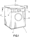
- the washing machine 1 shown in Figure 1 comprises a housing formed by a frame 20 in a U with a rear wall 25 joined to two side walls 27, a bottom cover 21 installed on the bottom of frame 20, a top cover 22 installed on the top of frame 20, as well was a front panel 23 with a mouth 23a and a control panel 24 in which the controls are installed and which enables access to the detergent compartment 1 installed on the front of frame 20.
- the rear wall 25 of the frame 20 has an access cut-out 25a that is closed by a removable rear closing cap 26, and through which the interior of the washing machine 1 is accessible.
- the bottom cover 21 comprises a central portion in the form of a wastewater collection tray 44.
- the upper surface of the wastewater collection tray 44 is tilted toward the drain 44a in which is mounted an essentially conventional wastewater sensing device 45.
- the washing machine is provided with a wash water reservoir 30 comprising two opposing side parts and joined by a rear part.
- an essentially conventional oscillating unit comprising a wash tub 2 in which rotates a wash drum 3 comprising a driven pulley 6 connected to a drive motor 4 by means of a fan belt 5.
- the drive motor 4 is arranged between the sides and the rear of the housing 20.
- the wash tub 2 is connected with the housing 20 on top by means of two retaining springs 9 anchored in internal flanges provided above on the opposing sides of the side walls of the housing 20, and below through dampers 7 articulated with respect to the damper supports 32.
- the supports 32 are installed on the reinforcements 32a joined to the respective side parts of the wash water reservoir 30.
- the bottom cover 21 comprises an exterior framework 21a bolted to the bottom of the frame 20 and a closing plate 21b that closes the interior void of the exterior framework 21a and is removably fixed to the exterior framework 21a by means of a removable fixing means.
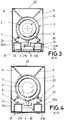
- the bottom cover 21 is articulated at its front to the wash water reservoir 30 by means of a hinge 33, while in the embodiment illustrated in Figure 4 it is bolted to a strip of the inner periphery the exterior framework 21a.
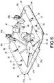
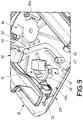
- FIGS 5 , 6 and 7 show a practical embodiment of the invention in which the bottom cover 21 comprises an exterior framework 21a, for example, made of sheet metal, above which is installed a wash water reservoir 30, and a hinged closing plate 21b, for example, made of a plastic material, which incorporates a wastewater collection tray 44 with a drain 44a of the type previously described with reference to Figure 2 , and in which is arranged the wastewater detection device (not shown in Figures 13 , 14 ), also as previously described with reference to Figure 2 .
- the wastewater detection device not shown in Figures 13 , 14
- the wash water reservoir 30 is installed on a support arranged at the bottom as shown schematically in Figure 3 .
- a first pump 40 intended for pumping wash liquid coming from the wash water reservoir 30 into the detergent compartment 10 (see Figure 1 ) as well as a second pump 41 intended to evacuate water from the wash tub 2.
- the closing plate 21b is articulated at its front to the wash water reservoir 30 by a hinge 33 that comprises each of two pins 33a that emerge horizontally from respective inner sides of the two side parts of the wash water reservoir 30, and each rotation bushing 33b at the free ends of the respective vertical projections 33c that emerge from the upper surface of the closing plate 21b.
- the hinge 33 provides freedom of downward movement once a lock is released when the hinged plate 21b moves in the top-down direction.
- the locking is realized by means of a series of complementary grooves and fins in the hinge pins 33a and the rotation bushing 33b that forming the articulation of the hinge 33, and that work together in a tongue-and-groove manner.
- the downward movement of the hinged closing plate 21b allows access to the interior of the washing machine, in particular to the pumps 40, 41, without needing to dismantle the tub 2 and the drum 3.
- the bottom cover 21 is joined to the bottom of the frame by means of a fixing screw 34 comprising a first lug 21c emerging horizontally from the rear edge of the closing plate 21b and a second lug 21d emerging horizontally from the rear edge of the exterior framework 21a in a position complementary to that of the first lug 21c.
- the first lug 21c has a vertical hole and the second lug has an internal thread 21d aligned with the vertical borehole such that a fixing screw 34a that passes through the vertical borehole of the first lug 21c can be screwed into the inner threads of the second lug 21d.
- an essentially conventional clipping fixing means 37 comprising, for example, vertically emerging nipples on the sides of the surface of the closing plate 21b which fit together elastically in the complementary retaining bushing of the exterior framework 21a.
- the exterior framework 21a For attachment to the frame, the exterior framework 21a comprises on the one hand a clipping fixing means 35 in the form of nipples that, for example, elastically fit into complementary apertures (not shown in the figures) at the bottom of the frame.
- the exterior framework 21a has through holes 36 in the opposing side strips, through which pass fixing screws (not shown in the figures) that screw into complementary holes provided in the bottom of the frame (not shown in the Figures).
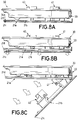
- FIGs 8A to 8C show the stages of opening the closing plate 21b with respect to the external framework 21a.
- the fixing screw 34a is unscrewed and then the closing plate 21b moves downward in a horizontal position against the resistance offered by the clipping fixing means 37 previously described with reference to Figures 5-7 , to reach the position shown in Figure 8B .
- the closing plate 21b rotates on the hinge 33 and swings relative to the exterior framework 21a, as shown in Figure 8C .
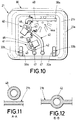
- Figures 9 to 12 show in more detail some of the characteristics of the closing plate 21b described above with reference to Figures 5 to 7 and 8A to 8C .
- connection from fluid inlet 46 of the first pump 40 is connected to a connector 30a provided on the inner side of one of the sides of the wash water reservoir 30 through a wash water outlet hose 48 that extends above the upper surface of the closing plate 21b while the outlet from the first pump 40 is connected to a first outlet connection 47 by means of a first wash liquid duct 42 integrated into the closing plate 21b.
- the first connection from the output connection 47 is connected to the detergent compartment by means of a resupply hose 50 (see Figures 12 and 13 ).
- the inlet connection 46 of the second pump 41 is connected to the wash tub 2 by means of a drain hose 49, while the outlet of the second pump 41 is connected to a second wash liquid duct 42 that has a second outlet connection 47 connected to an evacuation hose 51 (see Figures 12 and 13 ) that communicates with the drain from the washing machine 1.
- Figure 12 shows that the first wash liquid duct 42 is formed in the same body of the closing plate 21b that can be achieved, for example, in the molding of the closing plate 21b.
- Each of the pumps 40, 41 comprises a housing 43 partially integrated into the closing plate 21a.
- the wash liquid enters the interior of the housing 43 through the inlet connection 46 and is discharged under pressure through the outlet from the pump 40, 41 to the wash liquid duct 42.
- This structure is equally applicable to the second wash liquid duct.
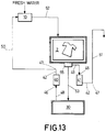
- FIG 13 shows a first embodiment of the hydraulic system of the washing machine.
- fresh water is supplied to the system by introducing it into the detergent compartment and leading it through a water supply hose 52 in the wash tub 2, and from there through the transfer duct 53 to the wash water reservoir 30 until there is enough water in wash tub 2 and the wash water reservoir 30 is full, after which the fresh water supply to the detergent compartment 10 is closed and the three-way valve 55 arranged in the outlet of wash tub 2 is closed.
- the three-way valve 55 When, after a wash cycle, it is necessary required to partially or completely evacuate the dirty wash liquid from tub 2, the three-way valve 55 is opened so that the dirty wash liquid can flow through the second wash water duct 42 to the drain hose 49, and the second pump 41 is operated to pump the dirty wash liquid through the discharge hose 51 to evacuate through the drain (not shown in the figures) of the washing machine 1, and the three-way valve 55 is closed.
- the first pump 40 When, after the evacuation of the wash liquid, continuing with a new wash cycle that requires the addition of wash water, the first pump 40 is operated to pump wash water from the wash water reservoir 30 through the wash water outlet hose 48, the first wash liquid duct 42 and the first hose 50 to the detergent compartment 10, from where it passes through the water supply hose 52 to the wash tub 2. After the wash tub 2 has been evacuated after a wash cycle, this can be done when all the wash water has been used, or only a portion thereof.
- this used wash water can be transferred to the wash water reservoir 30 by closing the access to the drain hose 49 by means of valve 55 and opening access to the transfer hose 53, such that the used wash water is transferred into the wash water reservoir 30 and, from there, by operating the first pump 40, can be brought through the wash water outlet hose 48, the first wash liquid duct 42 and the resupply hose 50 to the detergent compartment 10, from where it is recirculated, optionally being mixed with more fresh water and/or more detergent, to wash tub 2 via water supply hose 52.
- the tub 2, the wash water reservoir 30, the first pump 40, and the wash liquid duct 42 are part of a wash liquid recirculation circuit.
- the second embodiment of the hydraulic system of the washing machine shown in Figure 14 differs from the first embodiment illustrated in Figure 13 in that the wash tub 2 is not in hydraulic communication with the wash water reservoir 30 such that the valve 55 arranged at the outlet of the wash tub 2 is only two-way.
- the two-way valve 55 is opened so that the dirty wash liquid can flow through the second wash water duct 42 to the drain hose 49, and the second pump 41 is operated to pump the dirty wash liquid through the discharge hose 51 to evacuate through the drain (not shown in the figures) of the washing machine 1, and the two-way valve 55 is closed.
- fresh water can be supplied to the system by introducing it into the detergent compartment and leading it through the water supply hose 52 into the wash tub 2, and/or the wash water reservoir 30.
- the first pump 40 is operated to pump wash water from the wash water reservoir 30 through the wash water outlet hose 48, the first wash liquid duct 42 and the first hose 50 to the detergent compartment 10, from where it passes through the water supply hose 52 to the wash tub 2.
Description
- The present invention relates to the technical field of washing machines and, in particular, to a washing machine comprising a housing with a bottom cover, and a hydraulic flushing system, comprising a first pump motor and a second pump motor and at least one wash liquid duct.
- A washing machine of this generic type is disclosed in
US 2012/0090362 A1 . - A modern washing machine comprises a hydraulic system with wash water ducts and at least one pump to evacuate the water from tub to the outside through flexible hoses once the laundry has been cleaned or rinsed. Many washing machines also incorporate an "Aquastop" tray or wastewater collection tray having the shape of and constituting a bottom cover that is fixed to the frame, thereby defining a lower limit of a space inside the frame wherein the tub may be contained, possibly in a swinging fashion as in a laundry washer. To the "Aquastop" tray is connected an electrical wastewater detector device with a float element that, when the wastewater exceeds a certain level, sends a signal to a shutoff valve arranged in the water supply hose that is connected to the external tap to stop the supply of water to the washing machine.
- Washing machines with this type of hydraulic system are prone to a number of drawbacks when the utilizing the interior space, the access to elements such as the pump used for draining water from the wash tub, installation of the hydraulic system hoses in the factory, and access to the pump and various of these when repairs made.
-
Document EP 2 447 405 A1 discloses a washing machine comprising a recovery tank separate from the wash tank and suitable for containing a portion of recovered liquid, recycling means that introduce, during one of the steps of the washing program, the portion of recovered liquid from the recovery tank into the wash tank, and recovering means that, after at least one wash cycle step, convey a potion of liquid used during the wash cycle from the wash tank into the recovery tank. - It is an object of the present invention to overcome the drawbacks of the state of the art detailed above.
- With this object and other objects in view there is provided, in accordance with the invention, a washing machine as defined in the independent claim attached. Developments and embodiments of the invention are defined in dependent claims attached as well as in the subsequent disclosure and the Figures of the drawing attached.
- Accordingly there is provided, in accordance with the invention, a washing machine comprising a housing with a bottom cover, and a hydraulic flushing system, comprising a first pump motor and a second pump motor and at least one wash liquid duct. Further, at least a part of at least one hydraulic element selected from the at least one wash liquid duct and the first and the second pump motor is integrated into the bottom cover.
- The integration of the hydraulic elements in the bottom cover enables a reduction in assembly time for the hydraulic elements of the hydraulic washing system, such as pumps and hoses, since the positioning and interconnection of same are predetermined by the location of these hydraulics elements in the bottom cover. It is also possible to achieve a better utilization of the available space in the washing machine interior with which one can opt for a greater compactness and/or better arrangement of the hydraulic elements, compared to conventional washing machines. Moreover, the invention also provides design flexibility to be able to arrange the pump or pumps or water circulation duct connection or connections conveniently, for example, by reducing the risk of incorrect assembly or allowing easy and rapid accessibility for assembly/disassembly.
- At least part of the bottom cover can be manufactured by injection molding separately from a top and a bottom, then joined later, preferably by welding, most preferably ultrasonic welding. Alternatively, the bottom cover can be manufactured by blow molding.
- In accordance with an embodiment of the invention at least a portion of at least one wash liquid duct is integrated into the bottom cover.
- In accordance with another embodiment of the invention at least one of the pumps arranged in the bottom cover comprises a part of the pump motor housing that is at least partially integrated into the bottom cover, which reduces the transmission of noise and vibrations generated by the pump or pumps.
- In accordance with a further embodiment of the invention the bottom cover also comprises a wastewater collection tray, which is preferably integrated into the bottom cover, and which can be formed in the bottom cover during the molding process of the same.
- In accordance with yet another embodiment of the invention the washing machine comprises a frame and the bottom cover closes a bottom of the frame and, preferably, is at least partially detachable.
- This embodiment of the system allows access to the interior of the appliance, particularly to the pump or pumps, without dismantling the oscillating group (tub, drum, and drive motor), which is especially useful in frames formed into a U (closed in the rear), even if the appliance must be leaned back. To fix the cover to the frame, any releasable fixing method such as a clipping ("press fit") or screwing, can be used. Preferably, an airtight fixing is provided when the bottom cover incorporates an Aquastop tray.
- According to a further development this embodiment, at least a portion of the bottom cover can be hinged, and the bottom cover can be a one-piece cover or a two-piece cover comprising an exterior framework that is fixed to the bottom of the frame and a closing plate that is connected hingeably to the exterior framework.
- When the bottom cover is a one-piece cover, it can comprise a hinge by means of being articulated to the bottom of the washing machine frame or to an element arranged at the bottom of the frame.
- In turn, when the bottom cover is a two-piece cover, the exterior framework is firmly joined to the bottom of the frame, while the closing plate is articulated to the outer frame or to another element arranged on the bottom of the washing machine by means of a hinge, such that the closing plate is capable of swinging with respect to the exterior framework.
- In either case, the hinge is preferably designed to provide freedom of downward movement once a lock is released to move the cover in the top-down direction. Blocking can be accomplished, for example, by means of a series of grooves and fins at the hinge articulation that cooperate in a tongue-in-groove manner.
- According to yet another embodiment of the invention, the hydraulic system of the washing machine comprises at least one additional hydraulic element selected from among a wash water reservoir arranged in the bottom cover and a single wash tub arranged in the housing.
- In accordance with a development of this embodiment the hydraulic system comprises at least one wash water reservoir having a minimum capacity of 50%, and preferably 75%, of the total volume of water used in a washing cycle.
- In this regard it is noted that the capability of such a wash water reservoir depends on the internal space available within the washing machine. For example, there are washing machines having wash tubs with a capacity of approximately 50 liters of water that use approximately 15 liters of water in a wash cycle. In this case, the capacity of the wash water reservoir is at least 7.5 liters, preferably 11.25 liters.
- In accordance with yet a further embodiment of the invention the wash liquid duct is hydraulically connected to the wash water reservoir and/or wash tub. Likewise, the pump can be hydraulically connected to the wash water reservoir and/or wash tub.
- In still another embodiment of the invention the tub, one or more wash water reservoirs, one or more pumps, and one or more wash liquid ducts can form part of a wash liquid reuse circuit.
- Aspects and embodiments of the invention are described below in detail with reference to the Figures of the drawing attached. In particular,
-
Figure 1 is a front perspective view of a washing machine; -
Figure 2 is an exploded view of the housing of the washing machine illustrated inFigure 1 ; -
Figure 3 is a sectional view along the line A-A shown inFigure 1 , and shows a first embodiment; -
Figure 4 is another sectional view along the line A-A shown inFigure 1 , and shows a second embodiment; -
Figure 5 is a detailed view in rear perspective of a bottom cover provided with a wastewater collection tray that is installed in the wash water reservoir; -
Figure 6 is a rear perspective view of the bottom cover shown inFigure 5 , with the wastewater collection tray, but without the wash water reservoir; -
Figure 7 is a rear perspective view corresponding toFigure 5 , but with the wastewater collection tray in the open position -
Figures 8A to 8C are side elevational views showing stages of the opening of the wastewater collection tray of the bottom cover shown inFigure 5 ; -
Figure 9 is a front perspective view of the bottom cover shown inFigure 5 -
Figure 10 is a top view of the bottom cover shown inFigure 5 floor -
Figure 11 is a sectional view along line A-A shown inFigure 10 . -
Figure 12 is a sectional view along line B-B shown inFigure 10 . -
Figure 13 is a block diagram showing a first embodiment of the hydraulic system of the washing machine; and -
Figure 14 is a block diagram showing a second embodiment of the hydraulic system of the washing machine. - The
washing machine 1 shown inFigure 1 comprises a housing formed by aframe 20 in a U with a rear wall 25 joined to twoside walls 27, abottom cover 21 installed on the bottom offrame 20, atop cover 22 installed on the top offrame 20, as well was afront panel 23 with amouth 23a and acontrol panel 24 in which the controls are installed and which enables access to thedetergent compartment 1 installed on the front offrame 20. - The rear wall 25 of the
frame 20 has an access cut-out 25a that is closed by a removablerear closing cap 26, and through which the interior of thewashing machine 1 is accessible. - The
bottom cover 21 comprises a central portion in the form of awastewater collection tray 44. The upper surface of thewastewater collection tray 44 is tilted toward thedrain 44a in which is mounted an essentially conventionalwastewater sensing device 45. - The washing machine is provided with a
wash water reservoir 30 comprising two opposing side parts and joined by a rear part. - In the embodiment of the
washing machine 1 shown inFigure 2 , in the lower side parts of theside walls 27 of thehousing 20 are provided twosupports 31 for the wash water reservoir that serve to support which the opposing side parts of thewash water reservoir 30, which is installed above the bottom cover 21 (seeFigure 3 ), while in the embodiment of thewashing machine 1 ofFigure 4 thewash water reservoir 30 is installed on the upper surface of thebottom cover 21 which in turn is bolted to the bottom ofhousing 20. - As shown in
Figures 3 and 4 , inside thewashing machine 1 is an essentially conventional oscillating unit comprising awash tub 2 in which rotates awash drum 3 comprising a drivenpulley 6 connected to adrive motor 4 by means of afan belt 5. Thedrive motor 4 is arranged between the sides and the rear of thehousing 20. - The
wash tub 2 is connected with thehousing 20 on top by means of tworetaining springs 9 anchored in internal flanges provided above on the opposing sides of the side walls of thehousing 20, and below throughdampers 7 articulated with respect to the damper supports 32. Thesupports 32 are installed on thereinforcements 32a joined to the respective side parts of thewash water reservoir 30. - The
bottom cover 21 comprises anexterior framework 21a bolted to the bottom of theframe 20 and aclosing plate 21b that closes the interior void of theexterior framework 21a and is removably fixed to theexterior framework 21a by means of a removable fixing means. - In the embodiment illustrated in
Figure 3 , thebottom cover 21 is articulated at its front to thewash water reservoir 30 by means of ahinge 33, while in the embodiment illustrated inFigure 4 it is bolted to a strip of the inner periphery theexterior framework 21a. -
Figures 5 ,6 and7 show a practical embodiment of the invention in which thebottom cover 21 comprises anexterior framework 21a, for example, made of sheet metal, above which is installed awash water reservoir 30, and a hingedclosing plate 21b, for example, made of a plastic material, which incorporates awastewater collection tray 44 with adrain 44a of the type previously described with reference toFigure 2 , and in which is arranged the wastewater detection device (not shown inFigures 13 ,14 ), also as previously described with reference toFigure 2 . - The
wash water reservoir 30 is installed on a support arranged at the bottom as shown schematically inFigure 3 . - In the
closing plate 21b is arranged afirst pump 40 intended for pumping wash liquid coming from thewash water reservoir 30 into the detergent compartment 10 (seeFigure 1 ) as well as asecond pump 41 intended to evacuate water from thewash tub 2. - The
closing plate 21b is articulated at its front to thewash water reservoir 30 by ahinge 33 that comprises each of twopins 33a that emerge horizontally from respective inner sides of the two side parts of thewash water reservoir 30, and eachrotation bushing 33b at the free ends of the respectivevertical projections 33c that emerge from the upper surface of theclosing plate 21b. Thehinge 33 provides freedom of downward movement once a lock is released when the hingedplate 21b moves in the top-down direction. The locking is realized by means of a series of complementary grooves and fins in the hinge pins 33a and therotation bushing 33b that forming the articulation of thehinge 33, and that work together in a tongue-and-groove manner. The downward movement of the hingedclosing plate 21b allows access to the interior of the washing machine, in particular to thepumps tub 2 and thedrum 3. - From the rear, the
bottom cover 21 is joined to the bottom of the frame by means of a fixingscrew 34 comprising afirst lug 21c emerging horizontally from the rear edge of theclosing plate 21b and asecond lug 21d emerging horizontally from the rear edge of theexterior framework 21a in a position complementary to that of thefirst lug 21c. Thefirst lug 21c has a vertical hole and the second lug has aninternal thread 21d aligned with the vertical borehole such that a fixingscrew 34a that passes through the vertical borehole of thefirst lug 21c can be screwed into the inner threads of thesecond lug 21d. For fixing theclosing plate 21b to theexterior framework 21a, there is further provided an essentially conventional clipping fixing means 37 comprising, for example, vertically emerging nipples on the sides of the surface of theclosing plate 21b which fit together elastically in the complementary retaining bushing of theexterior framework 21a. - For attachment to the frame, the
exterior framework 21a comprises on the one hand a clipping fixing means 35 in the form of nipples that, for example, elastically fit into complementary apertures (not shown in the figures) at the bottom of the frame. On the other hand, theexterior framework 21a has throughholes 36 in the opposing side strips, through which pass fixing screws (not shown in the figures) that screw into complementary holes provided in the bottom of the frame (not shown in the Figures). -
Figures 8A to 8C show the stages of opening theclosing plate 21b with respect to theexternal framework 21a. Thus, when theclosing plate 21b is fixed to theexterior framework 21a as shown inFigure 8A , the fixingscrew 34a is unscrewed and then theclosing plate 21b moves downward in a horizontal position against the resistance offered by the clipping fixing means 37 previously described with reference toFigures 5-7 , to reach the position shown inFigure 8B . Then, theclosing plate 21b rotates on thehinge 33 and swings relative to theexterior framework 21a, as shown inFigure 8C . -
Figures 9 to 12 show in more detail some of the characteristics of theclosing plate 21b described above with reference toFigures 5 to 7 and8A to 8C . - As can be seen, the connection from
fluid inlet 46 of thefirst pump 40 is connected to aconnector 30a provided on the inner side of one of the sides of thewash water reservoir 30 through a washwater outlet hose 48 that extends above the upper surface of theclosing plate 21b while the outlet from thefirst pump 40 is connected to afirst outlet connection 47 by means of a firstwash liquid duct 42 integrated into theclosing plate 21b. The first connection from theoutput connection 47 is connected to the detergent compartment by means of a resupply hose 50 (seeFigures 12 and13 ). - The
inlet connection 46 of thesecond pump 41 is connected to thewash tub 2 by means of adrain hose 49, while the outlet of thesecond pump 41 is connected to a secondwash liquid duct 42 that has asecond outlet connection 47 connected to an evacuation hose 51 (seeFigures 12 and13 ) that communicates with the drain from thewashing machine 1. -
Figure 12 shows that the firstwash liquid duct 42 is formed in the same body of theclosing plate 21b that can be achieved, for example, in the molding of theclosing plate 21b. Each of thepumps housing 43 partially integrated into theclosing plate 21a. The wash liquid enters the interior of thehousing 43 through theinlet connection 46 and is discharged under pressure through the outlet from thepump wash liquid duct 42. This structure is equally applicable to the second wash liquid duct. -
Figure 13 shows a first embodiment of the hydraulic system of the washing machine. According to this embodiment, fresh water is supplied to the system by introducing it into the detergent compartment and leading it through awater supply hose 52 in thewash tub 2, and from there through thetransfer duct 53 to thewash water reservoir 30 until there is enough water inwash tub 2 and thewash water reservoir 30 is full, after which the fresh water supply to thedetergent compartment 10 is closed and the three-way valve 55 arranged in the outlet ofwash tub 2 is closed. When, after a wash cycle, it is necessary required to partially or completely evacuate the dirty wash liquid fromtub 2, the three-way valve 55 is opened so that the dirty wash liquid can flow through the secondwash water duct 42 to thedrain hose 49, and thesecond pump 41 is operated to pump the dirty wash liquid through thedischarge hose 51 to evacuate through the drain (not shown in the figures) of thewashing machine 1, and the three-way valve 55 is closed. - When, after the evacuation of the wash liquid, continuing with a new wash cycle that requires the addition of wash water, the
first pump 40 is operated to pump wash water from thewash water reservoir 30 through the washwater outlet hose 48, the firstwash liquid duct 42 and thefirst hose 50 to thedetergent compartment 10, from where it passes through thewater supply hose 52 to thewash tub 2. After thewash tub 2 has been evacuated after a wash cycle, this can be done when all the wash water has been used, or only a portion thereof. - Likewise, instead of draining the wash water from
wash tub 2 through thedrain hose 49, one can choose, when it is desired to reuse some or all of the used wash water that is evacuated fromwash tub 2, for example, such as water for soaking, this used wash water can be transferred to thewash water reservoir 30 by closing the access to thedrain hose 49 by means ofvalve 55 and opening access to thetransfer hose 53, such that the used wash water is transferred into thewash water reservoir 30 and, from there, by operating thefirst pump 40, can be brought through the washwater outlet hose 48, the firstwash liquid duct 42 and theresupply hose 50 to thedetergent compartment 10, from where it is recirculated, optionally being mixed with more fresh water and/or more detergent, to washtub 2 viawater supply hose 52. In this way, thetub 2, thewash water reservoir 30, thefirst pump 40, and thewash liquid duct 42 are part of a wash liquid recirculation circuit. - The second embodiment of the hydraulic system of the washing machine shown in
Figure 14 differs from the first embodiment illustrated inFigure 13 in that thewash tub 2 is not in hydraulic communication with thewash water reservoir 30 such that thevalve 55 arranged at the outlet of thewash tub 2 is only two-way. - As in the first embodiment of the hydraulic system, after a wash cycle, when it is necessary required to partially or completely evacuate the dirty wash liquid from
tub 2, the two-way valve 55 is opened so that the dirty wash liquid can flow through the secondwash water duct 42 to thedrain hose 49, and thesecond pump 41 is operated to pump the dirty wash liquid through thedischarge hose 51 to evacuate through the drain (not shown in the figures) of thewashing machine 1, and the two-way valve 55 is closed. - Moreover, fresh water can be supplied to the system by introducing it into the detergent compartment and leading it through the
water supply hose 52 into thewash tub 2, and/or thewash water reservoir 30. When, after the evacuation of the wash liquid, continuing with a new wash cycle that requires the addition of wash water, thefirst pump 40 is operated to pump wash water from thewash water reservoir 30 through the washwater outlet hose 48, the firstwash liquid duct 42 and thefirst hose 50 to thedetergent compartment 10, from where it passes through thewater supply hose 52 to thewash tub 2. -
- 1
- Washing machine
- 2
- Wash tub
- 3
- Rotating drum
- 4
- Drive motor
- 5
- Fan belt
- 6
- Belt pulley
- 7
- Damper
- 9
- Spring
- 10
- Detergent compartment
- 20
- Frame
- 21
- Bottom cover
- 21a
- External framework
- 21b
- Closing plate
- 21c
- First lug
- 21d
- Second lug
- 22
- Top cover
- 23
- Front panel
- 24
- Control panel
- 25
- Rear wall
- 25a
- Access cut-out
- 26
- Rear closure cover
- 27
- Side wall
- 30
- Wash water reservoir
- 30a
- Connector from the wash water reservoir
- 31
- Wash reservoir support
- 32
- Damper support
- 32a
- Reinforcement
- 33
- Hinge for reservoir hinged cover
- 33a
- Hinge pin
- 33b
- Rotation bushing
- 34
- Fastening screw from the bottom cover to the exterior framework
- 34a
- Fastening screw
- 35
- Fastening by clipping from the exterior framework to the frame
- 36
- Through hole for the screw from the exterior framework to the frame
- 37
- Fastening by clipping from the bottom cover to the exterior framework
- 40
- First pump motor
- 41
- Second pump motor
- 42
- Wash liquid duct
- 43
- Pump motor housing
- 44
- Wastewater collection tray
- 44a
- Drain
- 45
- Wastewater detector device
- 46
- Inlet connection to the pump motor
- 47
- Outlet connection to the pump motor
- 48
- Wash water outlet hose
- 49
- Tub drain hose
- 50
- Resupply hose
- 51
- Discharge hose
- 52
- Water drain hose
- 53
- Transfer hose
- 54
- Additional water drain hose
- 55
- Valve
Claims (13)
- Washing machine (1) comprising a housing with a bottom cover (21), and a hydraulic flushing system, comprising a first pump motor (40) and a second pump motor (41) and at least one wash liquid duct, characterized in that at least a part of at least one hydraulic element selected from the at least one wash liquid duct (42) and the first (40) and the second (41) pump motor is integrated into the bottom cover (21).
- Washing machine according to claim 1, characterized in that at least a part of the wash liquid duct (42) is integrated into the bottom cover (21).
- Washing machine (1) according to claim 1 or 2, characterized in that at least one of the first (40) and the second (41) pump motor is arranged in the bottom cover (21) and comprises a part of the pump motor housing (43) that is at least partially integrated into the bottom cover (21).
- Washing machine (1) according to one of the foregoing claims, characterized in that the bottom cover (21) comprises a wastewater collection tray (44).
- Washing machine (1) according to claim 4, characterized in that the wastewater collection tray (44) is integrated with the bottom cover (21).
- Washing machine (1) according to one of the foregoing claims, characterized in that the housing further comprises a frame (20) and the bottom cover (21) closes the bottom of the frame (20).
- Washing machine (1) according to one of the foregoing claims, characterized in that the bottom cover (21) is at least partially detachable.
- Washing machine (1) according to one of the foregoing claims, characterized in that at least part of the bottom cover (21) is hinged.
- Washing machine (1) according to one of the foregoing claims, characterized in that the hydraulic system comprises at least one additional hydraulic element selected from among a wash water reservoir (30) arranged in the bottom cover (21) and a single wash tub (2) arranged in the housing.
- Washing machine (1) according to claim 9, characterized in comprising at least one wash water reservoir (30) having a minimum capacity of 50%, preferably 75%, of the total volume of water used in a wash cycle.
- Washing machine (1) according to claim 9 or 10, characterized in that the wash liquid duct (42) is hydraulically connected to at least one hydraulic element selected from among the wash water reservoir (30) and the wash tub (2).
- Washing machine (1) according to claim 9, 10, or 11, characterized in that at least one of the first (40) and the second (41) pump motor is hydraulically connected to at least one hydraulic element selected from among the wash water reservoir (30) and the wash tub (2).
- Washing machine (1) according to one of claims 9 through 12, characterized in that at least one hydraulic element selected from the tub (2), at least one wash water reservoir (30), at least one pump motor (40) and at least one wash liquid duct (42) form part of a circuit for reuse of wash liquid.
Priority Applications (1)
| Application Number | Priority Date | Filing Date | Title |
|---|---|---|---|
| PL14199543T PL2889425T3 (en) | 2013-12-28 | 2014-12-22 | Washing machine with bottom cover |
Applications Claiming Priority (1)
| Application Number | Priority Date | Filing Date | Title |
|---|---|---|---|
| ES201331926A ES2539412B1 (en) | 2013-12-28 | 2013-12-28 | Washing machine with lower cover |
Publications (2)
| Publication Number | Publication Date |
|---|---|
| EP2889425A1 EP2889425A1 (en) | 2015-07-01 |
| EP2889425B1 true EP2889425B1 (en) | 2018-06-13 |
Family
ID=52146270
Family Applications (1)
| Application Number | Title | Priority Date | Filing Date |
|---|---|---|---|
| EP14199543.1A Active EP2889425B1 (en) | 2013-12-28 | 2014-12-22 | Washing machine with bottom cover |
Country Status (4)
| Country | Link |
|---|---|
| EP (1) | EP2889425B1 (en) |
| ES (2) | ES2539412B1 (en) |
| PL (1) | PL2889425T3 (en) |
| TR (1) | TR201810767T4 (en) |
Cited By (1)
| Publication number | Priority date | Publication date | Assignee | Title |
|---|---|---|---|---|
| WO2022022970A1 (en) * | 2020-07-29 | 2022-02-03 | BSH Hausgeräte GmbH | Laundry-care appliance having a washing medium tank |
Families Citing this family (1)
| Publication number | Priority date | Publication date | Assignee | Title |
|---|---|---|---|---|
| DE202017103815U1 (en) * | 2017-06-27 | 2017-08-24 | Polytec Plastics Germany Gmbh & Co. Kg | Washing machine, tumble dryer or dishwasher |
Citations (1)
| Publication number | Priority date | Publication date | Assignee | Title |
|---|---|---|---|---|
| EP2447405A1 (en) * | 2010-10-28 | 2012-05-02 | Candy S.p.A. | Method and device for washing laundry |
Family Cites Families (8)
| Publication number | Priority date | Publication date | Assignee | Title |
|---|---|---|---|---|
| IT225651Y1 (en) * | 1991-06-13 | 1997-01-13 | Zanussi Elettrodomestici | DISHWASHER WITH CONTROL PANEL |
| KR0131683Y1 (en) * | 1993-07-30 | 1999-04-15 | 김광호 | Anti-noise device of a washing machine |
| IT232516Y1 (en) * | 1994-07-29 | 2000-01-10 | Ramalplast S R L | EQUIPPED BRUSH, FOR COVERING HOUSEHOLD APPLIANCES. |
| ES2191564B1 (en) * | 2002-02-20 | 2004-12-16 | Plasticos Mondragon, S.A. | COVER MOLDED FOR APPLIANCES, WITH ELECTRONIC CONTROL INCORPORATED. |
| ES2224827B1 (en) * | 2002-12-17 | 2007-09-16 | Incaelec, S.L. | WASHING MACHINE PROVIDED WITH A LOWER DRAWER. |
| US20060081014A1 (en) * | 2004-09-10 | 2006-04-20 | Lg Electronics Inc. | Washing apparatus |
| CN101012616A (en) * | 2007-01-26 | 2007-08-08 | 许继海 | Fountain barrel washing machine having self-contained water tank |
| US20120090362A1 (en) * | 2008-12-31 | 2012-04-19 | Young Jin Hwang | Laundry machine |
-
2013
- 2013-12-28 ES ES201331926A patent/ES2539412B1/en not_active Revoked
-
2014
- 2014-12-22 EP EP14199543.1A patent/EP2889425B1/en active Active
- 2014-12-22 ES ES14199543.1T patent/ES2684406T3/en active Active
- 2014-12-22 TR TR2018/10767T patent/TR201810767T4/en unknown
- 2014-12-22 PL PL14199543T patent/PL2889425T3/en unknown
Patent Citations (1)
| Publication number | Priority date | Publication date | Assignee | Title |
|---|---|---|---|---|
| EP2447405A1 (en) * | 2010-10-28 | 2012-05-02 | Candy S.p.A. | Method and device for washing laundry |
Cited By (1)
| Publication number | Priority date | Publication date | Assignee | Title |
|---|---|---|---|---|
| WO2022022970A1 (en) * | 2020-07-29 | 2022-02-03 | BSH Hausgeräte GmbH | Laundry-care appliance having a washing medium tank |
Also Published As
| Publication number | Publication date |
|---|---|
| TR201810767T4 (en) | 2018-08-27 |
| PL2889425T3 (en) | 2018-11-30 |
| ES2684406T3 (en) | 2018-10-02 |
| ES2539412A1 (en) | 2015-06-30 |
| EP2889425A1 (en) | 2015-07-01 |
| ES2539412B1 (en) | 2016-04-21 |
Similar Documents
| Publication | Publication Date | Title |
|---|---|---|
| US20140083144A1 (en) | Wall-mounted drum-type washing machine | |
| US11001953B2 (en) | Washing machine | |
| KR20230165737A (en) | Washing machine | |
| EP2889425B1 (en) | Washing machine with bottom cover | |
| KR101225167B1 (en) | Washing Machine having Drain Casing | |
| CN110607657B (en) | Washing machine | |
| CN110607653B (en) | Washing machine | |
| KR100826206B1 (en) | drum type washer | |
| KR20180074490A (en) | Washing machine | |
| US11713533B2 (en) | Washing machine | |
| CN110607633A (en) | Washing machine | |
| CN110607634B (en) | Washing machine | |
| CN110607649B (en) | Washing machine | |
| KR101133616B1 (en) | Washing machine | |
| KR101248745B1 (en) | Drum type washing machine | |
| US8336343B2 (en) | Washing machine having remaining water discharge passage | |
| CN110578237A (en) | drum washing machine and water inlet system thereof | |
| KR20010088209A (en) | Drum washing machine | |
| CN110607651A (en) | Washing machine | |
| EP4357516A1 (en) | Washing machine and clothing treatment apparatus | |
| KR101270613B1 (en) | Washing machine | |
| CN110607646A (en) | Washing machine | |
| CN110607647A (en) | Washing machine | |
| CN110607658A (en) | Washing machine | |
| CN110607654A (en) | Washing machine |
Legal Events
| Date | Code | Title | Description |
|---|---|---|---|
| PUAI | Public reference made under article 153(3) epc to a published international application that has entered the european phase |
Free format text: ORIGINAL CODE: 0009012 |
|
| 17P | Request for examination filed |
Effective date: 20141222 |
|
| AK | Designated contracting states |
Kind code of ref document: A1 Designated state(s): AL AT BE BG CH CY CZ DE DK EE ES FI FR GB GR HR HU IE IS IT LI LT LU LV MC MK MT NL NO PL PT RO RS SE SI SK SM TR |
|
| AX | Request for extension of the european patent |
Extension state: BA ME |
|
| R17P | Request for examination filed (corrected) |
Effective date: 20160104 |
|
| RBV | Designated contracting states (corrected) |
Designated state(s): AL AT BE BG CH CY CZ DE DK EE ES FI FR GB GR HR HU IE IS IT LI LT LU LV MC MK MT NL NO PL PT RO RS SE SI SK SM TR |
|
| 17Q | First examination report despatched |
Effective date: 20170411 |
|
| GRAP | Despatch of communication of intention to grant a patent |
Free format text: ORIGINAL CODE: EPIDOSNIGR1 |
|
| INTG | Intention to grant announced |
Effective date: 20180201 |
|
| GRAS | Grant fee paid |
Free format text: ORIGINAL CODE: EPIDOSNIGR3 |
|
| GRAA | (expected) grant |
Free format text: ORIGINAL CODE: 0009210 |
|
| AK | Designated contracting states |
Kind code of ref document: B1 Designated state(s): AL AT BE BG CH CY CZ DE DK EE ES FI FR GB GR HR HU IE IS IT LI LT LU LV MC MK MT NL NO PL PT RO RS SE SI SK SM TR |
|
| REG | Reference to a national code |
Ref country code: GB Ref legal event code: FG4D |
|
| REG | Reference to a national code |
Ref country code: CH Ref legal event code: EP Ref country code: AT Ref legal event code: REF Ref document number: 1008636 Country of ref document: AT Kind code of ref document: T Effective date: 20180615 |
|
| REG | Reference to a national code |
Ref country code: IE Ref legal event code: FG4D |
|
| REG | Reference to a national code |
Ref country code: DE Ref legal event code: R096 Ref document number: 602014026904 Country of ref document: DE |
|
| REG | Reference to a national code |
Ref country code: ES Ref legal event code: FG2A Ref document number: 2684406 Country of ref document: ES Kind code of ref document: T3 Effective date: 20181002 |
|
| REG | Reference to a national code |
Ref country code: NL Ref legal event code: MP Effective date: 20180613 |
|
| REG | Reference to a national code |
Ref country code: LT Ref legal event code: MG4D |
|
| PG25 | Lapsed in a contracting state [announced via postgrant information from national office to epo] |
Ref country code: NO Free format text: LAPSE BECAUSE OF FAILURE TO SUBMIT A TRANSLATION OF THE DESCRIPTION OR TO PAY THE FEE WITHIN THE PRESCRIBED TIME-LIMIT Effective date: 20180913 Ref country code: SE Free format text: LAPSE BECAUSE OF FAILURE TO SUBMIT A TRANSLATION OF THE DESCRIPTION OR TO PAY THE FEE WITHIN THE PRESCRIBED TIME-LIMIT Effective date: 20180613 Ref country code: BG Free format text: LAPSE BECAUSE OF FAILURE TO SUBMIT A TRANSLATION OF THE DESCRIPTION OR TO PAY THE FEE WITHIN THE PRESCRIBED TIME-LIMIT Effective date: 20180913 Ref country code: FI Free format text: LAPSE BECAUSE OF FAILURE TO SUBMIT A TRANSLATION OF THE DESCRIPTION OR TO PAY THE FEE WITHIN THE PRESCRIBED TIME-LIMIT Effective date: 20180613 Ref country code: CY Free format text: LAPSE BECAUSE OF FAILURE TO SUBMIT A TRANSLATION OF THE DESCRIPTION OR TO PAY THE FEE WITHIN THE PRESCRIBED TIME-LIMIT Effective date: 20180613 Ref country code: LT Free format text: LAPSE BECAUSE OF FAILURE TO SUBMIT A TRANSLATION OF THE DESCRIPTION OR TO PAY THE FEE WITHIN THE PRESCRIBED TIME-LIMIT Effective date: 20180613 |
|
| PG25 | Lapsed in a contracting state [announced via postgrant information from national office to epo] |
Ref country code: LV Free format text: LAPSE BECAUSE OF FAILURE TO SUBMIT A TRANSLATION OF THE DESCRIPTION OR TO PAY THE FEE WITHIN THE PRESCRIBED TIME-LIMIT Effective date: 20180613 Ref country code: RS Free format text: LAPSE BECAUSE OF FAILURE TO SUBMIT A TRANSLATION OF THE DESCRIPTION OR TO PAY THE FEE WITHIN THE PRESCRIBED TIME-LIMIT Effective date: 20180613 Ref country code: HR Free format text: LAPSE BECAUSE OF FAILURE TO SUBMIT A TRANSLATION OF THE DESCRIPTION OR TO PAY THE FEE WITHIN THE PRESCRIBED TIME-LIMIT Effective date: 20180613 Ref country code: GR Free format text: LAPSE BECAUSE OF FAILURE TO SUBMIT A TRANSLATION OF THE DESCRIPTION OR TO PAY THE FEE WITHIN THE PRESCRIBED TIME-LIMIT Effective date: 20180914 |
|
| REG | Reference to a national code |
Ref country code: AT Ref legal event code: MK05 Ref document number: 1008636 Country of ref document: AT Kind code of ref document: T Effective date: 20180613 |
|
| PG25 | Lapsed in a contracting state [announced via postgrant information from national office to epo] |
Ref country code: NL Free format text: LAPSE BECAUSE OF FAILURE TO SUBMIT A TRANSLATION OF THE DESCRIPTION OR TO PAY THE FEE WITHIN THE PRESCRIBED TIME-LIMIT Effective date: 20180613 |
|
| PG25 | Lapsed in a contracting state [announced via postgrant information from national office to epo] |
Ref country code: RO Free format text: LAPSE BECAUSE OF FAILURE TO SUBMIT A TRANSLATION OF THE DESCRIPTION OR TO PAY THE FEE WITHIN THE PRESCRIBED TIME-LIMIT Effective date: 20180613 Ref country code: CZ Free format text: LAPSE BECAUSE OF FAILURE TO SUBMIT A TRANSLATION OF THE DESCRIPTION OR TO PAY THE FEE WITHIN THE PRESCRIBED TIME-LIMIT Effective date: 20180613 Ref country code: AT Free format text: LAPSE BECAUSE OF FAILURE TO SUBMIT A TRANSLATION OF THE DESCRIPTION OR TO PAY THE FEE WITHIN THE PRESCRIBED TIME-LIMIT Effective date: 20180613 Ref country code: IS Free format text: LAPSE BECAUSE OF FAILURE TO SUBMIT A TRANSLATION OF THE DESCRIPTION OR TO PAY THE FEE WITHIN THE PRESCRIBED TIME-LIMIT Effective date: 20181013 Ref country code: EE Free format text: LAPSE BECAUSE OF FAILURE TO SUBMIT A TRANSLATION OF THE DESCRIPTION OR TO PAY THE FEE WITHIN THE PRESCRIBED TIME-LIMIT Effective date: 20180613 Ref country code: SK Free format text: LAPSE BECAUSE OF FAILURE TO SUBMIT A TRANSLATION OF THE DESCRIPTION OR TO PAY THE FEE WITHIN THE PRESCRIBED TIME-LIMIT Effective date: 20180613 |
|
| PG25 | Lapsed in a contracting state [announced via postgrant information from national office to epo] |
Ref country code: IT Free format text: LAPSE BECAUSE OF FAILURE TO SUBMIT A TRANSLATION OF THE DESCRIPTION OR TO PAY THE FEE WITHIN THE PRESCRIBED TIME-LIMIT Effective date: 20180613 Ref country code: SM Free format text: LAPSE BECAUSE OF FAILURE TO SUBMIT A TRANSLATION OF THE DESCRIPTION OR TO PAY THE FEE WITHIN THE PRESCRIBED TIME-LIMIT Effective date: 20180613 |
|
| PGFP | Annual fee paid to national office [announced via postgrant information from national office to epo] |
Ref country code: GB Payment date: 20181219 Year of fee payment: 5 |
|
| REG | Reference to a national code |
Ref country code: DE Ref legal event code: R097 Ref document number: 602014026904 Country of ref document: DE |
|
| PLBE | No opposition filed within time limit |
Free format text: ORIGINAL CODE: 0009261 |
|
| STAA | Information on the status of an ep patent application or granted ep patent |
Free format text: STATUS: NO OPPOSITION FILED WITHIN TIME LIMIT |
|
| PGFP | Annual fee paid to national office [announced via postgrant information from national office to epo] |
Ref country code: DK Payment date: 20181023 Year of fee payment: 14 |
|
| 26N | No opposition filed |
Effective date: 20190314 |
|
| PG25 | Lapsed in a contracting state [announced via postgrant information from national office to epo] |
Ref country code: DK Free format text: LAPSE BECAUSE OF FAILURE TO SUBMIT A TRANSLATION OF THE DESCRIPTION OR TO PAY THE FEE WITHIN THE PRESCRIBED TIME-LIMIT Effective date: 20180613 Ref country code: SI Free format text: LAPSE BECAUSE OF FAILURE TO SUBMIT A TRANSLATION OF THE DESCRIPTION OR TO PAY THE FEE WITHIN THE PRESCRIBED TIME-LIMIT Effective date: 20180613 |
|
| REG | Reference to a national code |
Ref country code: CH Ref legal event code: PL |
|
| PG25 | Lapsed in a contracting state [announced via postgrant information from national office to epo] |
Ref country code: MC Free format text: LAPSE BECAUSE OF FAILURE TO SUBMIT A TRANSLATION OF THE DESCRIPTION OR TO PAY THE FEE WITHIN THE PRESCRIBED TIME-LIMIT Effective date: 20180613 Ref country code: LU Free format text: LAPSE BECAUSE OF NON-PAYMENT OF DUE FEES Effective date: 20181222 |
|
| REG | Reference to a national code |
Ref country code: IE Ref legal event code: MM4A |
|
| REG | Reference to a national code |
Ref country code: BE Ref legal event code: MM Effective date: 20181231 |
|
| PG25 | Lapsed in a contracting state [announced via postgrant information from national office to epo] |
Ref country code: FR Free format text: LAPSE BECAUSE OF NON-PAYMENT OF DUE FEES Effective date: 20181231 Ref country code: IE Free format text: LAPSE BECAUSE OF NON-PAYMENT OF DUE FEES Effective date: 20181222 |
|
| PG25 | Lapsed in a contracting state [announced via postgrant information from national office to epo] |
Ref country code: AL Free format text: LAPSE BECAUSE OF FAILURE TO SUBMIT A TRANSLATION OF THE DESCRIPTION OR TO PAY THE FEE WITHIN THE PRESCRIBED TIME-LIMIT Effective date: 20180613 Ref country code: BE Free format text: LAPSE BECAUSE OF NON-PAYMENT OF DUE FEES Effective date: 20181231 |
|
| PG25 | Lapsed in a contracting state [announced via postgrant information from national office to epo] |
Ref country code: LI Free format text: LAPSE BECAUSE OF NON-PAYMENT OF DUE FEES Effective date: 20181231 Ref country code: CH Free format text: LAPSE BECAUSE OF NON-PAYMENT OF DUE FEES Effective date: 20181231 |
|
| PG25 | Lapsed in a contracting state [announced via postgrant information from national office to epo] |
Ref country code: MT Free format text: LAPSE BECAUSE OF NON-PAYMENT OF DUE FEES Effective date: 20181222 |
|
| PG25 | Lapsed in a contracting state [announced via postgrant information from national office to epo] |
Ref country code: PT Free format text: LAPSE BECAUSE OF FAILURE TO SUBMIT A TRANSLATION OF THE DESCRIPTION OR TO PAY THE FEE WITHIN THE PRESCRIBED TIME-LIMIT Effective date: 20180613 |
|
| PG25 | Lapsed in a contracting state [announced via postgrant information from national office to epo] |
Ref country code: HU Free format text: LAPSE BECAUSE OF FAILURE TO SUBMIT A TRANSLATION OF THE DESCRIPTION OR TO PAY THE FEE WITHIN THE PRESCRIBED TIME-LIMIT; INVALID AB INITIO Effective date: 20141222 Ref country code: MK Free format text: LAPSE BECAUSE OF NON-PAYMENT OF DUE FEES Effective date: 20180613 |
|
| GBPC | Gb: european patent ceased through non-payment of renewal fee |
Effective date: 20191222 |
|
| PG25 | Lapsed in a contracting state [announced via postgrant information from national office to epo] |
Ref country code: GB Free format text: LAPSE BECAUSE OF NON-PAYMENT OF DUE FEES Effective date: 20191222 |
|
| REG | Reference to a national code |
Ref country code: ES Ref legal event code: FD2A Effective date: 20210524 |
|
| PG25 | Lapsed in a contracting state [announced via postgrant information from national office to epo] |
Ref country code: ES Free format text: LAPSE BECAUSE OF NON-PAYMENT OF DUE FEES Effective date: 20191223 |
|
| REG | Reference to a national code |
Ref country code: DE Ref legal event code: R084 Ref document number: 602014026904 Country of ref document: DE |
|
| PGFP | Annual fee paid to national office [announced via postgrant information from national office to epo] |
Ref country code: PL Payment date: 20221212 Year of fee payment: 9 |
|
| PGFP | Annual fee paid to national office [announced via postgrant information from national office to epo] |
Ref country code: TR Payment date: 20221221 Year of fee payment: 9 |
|
| PGFP | Annual fee paid to national office [announced via postgrant information from national office to epo] |
Ref country code: DE Payment date: 20231231 Year of fee payment: 10 |
|
| PGFP | Annual fee paid to national office [announced via postgrant information from national office to epo] |
Ref country code: PL Payment date: 20231211 Year of fee payment: 10 |