EP2889233A1 - An automated or semi-automated storage and retrieval system at differentiated temperatures - Google Patents
An automated or semi-automated storage and retrieval system at differentiated temperatures Download PDFInfo
- Publication number
- EP2889233A1 EP2889233A1 EP14200638.6A EP14200638A EP2889233A1 EP 2889233 A1 EP2889233 A1 EP 2889233A1 EP 14200638 A EP14200638 A EP 14200638A EP 2889233 A1 EP2889233 A1 EP 2889233A1
- Authority
- EP
- European Patent Office
- Prior art keywords
- load units
- electrical contact
- automated
- storage locations
- storage
- Prior art date
- Legal status (The legal status is an assumption and is not a legal conclusion. Google has not performed a legal analysis and makes no representation as to the accuracy of the status listed.)
- Granted
Links
- 238000001816 cooling Methods 0.000 claims abstract description 10
- 238000010438 heat treatment Methods 0.000 claims abstract description 10
- 239000004020 conductor Substances 0.000 description 2
- 238000012423 maintenance Methods 0.000 description 2
- 230000002146 bilateral effect Effects 0.000 description 1
- 230000001419 dependent effect Effects 0.000 description 1
- 230000008021 deposition Effects 0.000 description 1
- 238000005265 energy consumption Methods 0.000 description 1
- 230000007613 environmental effect Effects 0.000 description 1
- 230000003993 interaction Effects 0.000 description 1
Images

Classifications
-
- B—PERFORMING OPERATIONS; TRANSPORTING
- B65—CONVEYING; PACKING; STORING; HANDLING THIN OR FILAMENTARY MATERIAL
- B65G—TRANSPORT OR STORAGE DEVICES, e.g. CONVEYORS FOR LOADING OR TIPPING, SHOP CONVEYOR SYSTEMS OR PNEUMATIC TUBE CONVEYORS
- B65G1/00—Storing articles, individually or in orderly arrangement, in warehouses or magazines
- B65G1/02—Storage devices
- B65G1/04—Storage devices mechanical
- B65G1/0407—Storage devices mechanical using stacker cranes
Definitions
- the present invention generally pertains to the field of automated or semi-automated storage of load units. Particularly, the invention relates to an automated or semi-automated system for the storage and retrieval of load units at differentiated temperatures.
- the chosen solution to the problem of conserving goods at a suitable temperature is that of cooling or heating the whole of the warehouse containing the store to constant thermal conditions, set to a single temperature level.
- One object of the present invention is to optimize the ratio between the volumes cooled and/or heated and the goods that are cooled and/or heated, thus making the operating costs quite lower than those of the prior art solutions, while providing greater flexibility in the operation of the store.
- Another object of the present invention is to avoid the multiplication of stores which becomes necessary when storage units have to be climate-controlled at different temperatures.
- the shelves of an automated or semi-automated store have horizontal support guides, on which the various load units that may need to be heated or cooled can be placed; the horizontal guides are associated with stationary electrical contacts, interfaced with electrical contacts fixed to the load units that are to be conserved at a temperature other than that of the surrounding environment, for the purpose of supplying electrical power to cooling and/or heating devices associated with said load units.
- the load units to be heated or cooled are made in such a way that the goods are contained and protected within a closed or closable casing having thermally insulated walls.
- each load unit is thermally insulated from all the others present in the store, and since the load unit is associated with an independent device for cooling or heating the goods contained in the unit, it is unnecessary to provide further climate control of the whole storage environment, and the aforementioned advantages are therefore obtained.
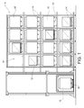
- the number 9 indicates as a whole an automated store for the storage of load units 12 at different temperatures.
- the expression "automated store” or “semi-automated store” indicates an automated or semi-automated system for the storage and retrieval of the load units 12.
- the store 9 comprises a plurality of storage locations 10, each capable of housing at least one load unit 12.
- the load units 12 may be of the conventional (non-climate-controlled) type, or of the cooled and/or heated type, for the control and maintenance of a given optimal conservation temperature.
- the storage locations 10 may be arranged with respect to one another in an ordered manner, in one-dimensional juxtaposition (that is to say, with the storage locations aligned in a single array), in two-dimensional juxtaposition (in a horizontal or vertical plane), or in three-dimensional juxtaposition (in a system of three orthogonal Cartesian axes, thus generating a block with a depth of two or more storage locations in the three directions).
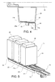
- the load units 12 can be stored in (or retrieved from) storage locations by handling means 16 of a known type, such as self-propelled vehicles (of the type known as "satellites"), or by telescopic forks ( Fig. 5 ) associated with Cartesian rack feeders.
- the satellite may be associated with a self-propelled shuttle (not shown) as described, for example, in International patent application No. PCT/IB2014/060649 , incorporated herein by reference.
- the handling means for transferring the load units from and towards the storage locations may be telescopic forks carried by conventional elevator trucks (not shown).
- Fig. 2 shows a detail of the automated store 9 according to an embodiment in which the handling means 16 is a self-propelled vehicle (satellite) movable on projections 14c of horizontal support guides 14, which are arranged in pairs in such a way that all the storage locations 10 can be reached, for the purpose of supporting the load units 12.
- the handling means 16 is a self-propelled vehicle (satellite) movable on projections 14c of horizontal support guides 14, which are arranged in pairs in such a way that all the storage locations 10 can be reached, for the purpose of supporting the load units 12.
- the handling means 16 may be fitted with a liftable plate 16a adapted to carry the load units 12 during the storage or retrieval operations.
- the load units are of the cooled and/or heated type; these units comprise an outer casing 18 shaped so as to enclose, in a thermally insulated manner, an internal volume containing the goods to be stored. It is to be understood that each unit having an insulating casing is capable of ensuring the maintenance of a specified temperature level, regardless of the requirements of the other cooled and/or heated units that may be present in the store. Purely by way of example, the three load units shown in Fig.
- the present invention allows the greatest flexibility in terms of the determination of the conservation temperatures that may be required by the various load units within a single environment. Furthermore, the present invention allows cooled and/or heated load units to be alternated with conventional load units in the various storage locations.
- the heated and/or cooled load units are each provided with a cooling or heating device 20 located, in a non-limiting embodiment shown in Fig. 2 , on the top part of the casing 18 of the respective load unit.
- the cooling or heating devices may be incorporated inside the casing 18 of the heated and/or cooled load unit. These devices are supplied with electrical power through the physical contact between two conductive elements (electrical contacts) 22 and 24, associated with the load unit and the support guide respectively.
- Fig. 3 shows a detail of the portion of the store shown in Fig. 2 , in which it may be seen that the load unit is supported on the guide 14 by supporting feet 26.
- the supporting feet 26 of each load unit may be present in variable numbers and types; that is to say, they may extend along all or part of the length of the side on which the load unit bears, instead of providing a support of the discrete type.
- a stationary electrical contact 22 is associated with the guide 14.
- the stationary electrical contacts 22 associated with each location are connected to one another along the guide 14 by means of a conductor 22a.
- the horizontal support guide 14 is shaped so as to have a horizontal top surface 14a, capable of supporting the load unit by contact with a lower portion 26a of the supporting foot 26, and a vertical flange 14b, preferably contiguous with and perpendicular to the horizontal top surface 14a of the guide.
- the vertical flange 14b is associated with the stationary electrical contact 22 relating to the storage location 10 in question.
- the stationary electrical contact 22 is fixed to the vertical flange 14b.
- the vertical flange 14b projects laterally or transversely from the guide 14.
- the stationary electrical contact 22 projects laterally or transversely from the vertical flange 14b.
- the supporting foot 26 of the heated and/or cooled load unit 12 incorporates a first electrical contact 24 which, by interfacing with the stationary electrical contact 22 fixed to the guide, supplies the cooling and/or heating device 20 of the respective load unit through a conducting element 22b.
- the first electrical contact 24 is incorporated into the lower portion 26a of the supporting foot 26 of the load unit, in the form of a conductive plate which draws electrical energy from the stationary contact 22 fixed to the guide 14, at the moment when the conductive plate and the external contact are superimposed.
- the handling means 16 should be capable of positioning the load unit in the corresponding storage location in a sufficiently precise way to enable the stationary contact 22 and the first electrical contact 24 (fixed to the supporting foot) to be correctly aligned.
- the stationary electrical contact 22 provides a top surface positioned substantially flush with the horizontal top surface 14a of the guide, or slightly raised above the horizontal top surface 14a of the guide. This configuration ensures a physical contact and electrical conduction between the electrical contacts 22 and 24 when the load unit bears on the guide 14 by means of its supporting foot 26.
- the geometry of the electrical contact is not a limiting feature, since other systems of interaction between the conductors fixed to the guide 14 and to the supporting foot 26 respectively may be provided, for example by plug and socket connections (not shown) or sliding contact connections (not shown).
- the first electrical contact 24, fixed to the load unit 12 is positioned on the outside of the supporting foot 26, but other configurations are not excluded.
- the electrical contacts are of the low or very low voltage direct current type, with voltages preferably less than or equal to 120 V, or even more preferably less than or equal to 72 V.
- the choice of handling means for moving the load units along the guides is not limited to the embodiment described herein (self-propelled satellite vehicles), but may include all the currently available solutions (automatic or semi-automatic), including the telescopic forks used in the example of Fig. 5 for the storage and retrieval of the load units 12.
- Forks commonly associated with shelving rack feeders or lift trucks (not shown), may be used for the bilateral frontal deposition of the load units in single, double or triple depths, depending on the number of elements which move (travel) relative to the fixed body, while satellite vehicles (possibly coupled to shuttles or shelving rack feeders, which are also not shown) may also be used with multiple depths.
- the present invention therefore makes it possible to store different types of product, which require different conservation temperatures, within the same non-climate-controlled store.
- the electrical power supply provided in all or part of the store area can be used to stabilize the temperatures of the containers over time and over a wide range of temperatures, which may be below zero or higher than the ambient temperature.
- the automated or semi-automated storage and retrieval system with differentiated temperatures provides very high energy efficiency compared with an ordinary cooled and/or heated store, since the latter requires climate control of the whole volume, with a very high ratio between the cooled volumes and the cooled goods, resulting in high operating costs with lower flexibility.
Landscapes
- Engineering & Computer Science (AREA)
- Mechanical Engineering (AREA)
- Devices That Are Associated With Refrigeration Equipment (AREA)
- Control Of Vending Devices And Auxiliary Devices For Vending Devices (AREA)
- Control Of Temperature (AREA)
Abstract
Description
- The present invention generally pertains to the field of automated or semi-automated storage of load units. Particularly, the invention relates to an automated or semi-automated system for the storage and retrieval of load units at differentiated temperatures.
- Many types of goods, particularly in the food industry, require specific conservation conditions, for which the control of environmental parameters such as humidity and temperature is very commonly required. In order to ensure the desired conservation conditions, it is necessary at present to provide climate control of a whole store at a given temperature. This solution, used in the known art, has considerable drawbacks in many respects, particularly as regards the poor or non-existent controllability of any thermal gradient which may be desired, for example, for the conservation of goods at different temperatures.
- In the current state of the art, the chosen solution to the problem of conserving goods at a suitable temperature is that of cooling or heating the whole of the warehouse containing the store to constant thermal conditions, set to a single temperature level.
- This requires high expenditure in terms of energy and financial resources, since a number of stores equal to the number of desired conservation temperatures must be provided. Furthermore, the energy consumption for the climate control of the environment is at the same level regardless of the volume and quantity of goods to be conserved at the temperature in question. The losses in financial and energy terms increase with a decrease in the ratio between the volume that is actually to be climate-controlled and the volume of the climate-controlled warehouse.
- One object of the present invention is to optimize the ratio between the volumes cooled and/or heated and the goods that are cooled and/or heated, thus making the operating costs quite lower than those of the prior art solutions, while providing greater flexibility in the operation of the store.
- Another object of the present invention is to avoid the multiplication of stores which becomes necessary when storage units have to be climate-controlled at different temperatures.
- The aforesaid objects and advantages, and others, are achieved, according to one aspect of the invention, by a system having the characteristics defined in Claim 1. Preferred embodiments of the invention are defined in the dependent claims.
- Briefly, the shelves of an automated or semi-automated store have horizontal support guides, on which the various load units that may need to be heated or cooled can be placed; the horizontal guides are associated with stationary electrical contacts, interfaced with electrical contacts fixed to the load units that are to be conserved at a temperature other than that of the surrounding environment, for the purpose of supplying electrical power to cooling and/or heating devices associated with said load units. The load units to be heated or cooled are made in such a way that the goods are contained and protected within a closed or closable casing having thermally insulated walls. Thus, since each load unit is thermally insulated from all the others present in the store, and since the load unit is associated with an independent device for cooling or heating the goods contained in the unit, it is unnecessary to provide further climate control of the whole storage environment, and the aforementioned advantages are therefore obtained.
- The structural and functional characteristics of some preferred embodiments of an automated or semi-automated system according to the invention will now be described.
- Reference is made to the attached drawings, in which:
-
Fig. 1 is a schematic view of an automated store according to one embodiment of the invention; -
Fig. 2 is a schematic perspective view of a set of load units contained in the store ofFig. 1 ; -
Fig. 3 is an enlarged schematic perspective view of a detail ofFig. 2 ; -
Fig. 4 is a schematic front view of a detail of the portion of store ofFig. 3 ; and -
Fig. 5 is a schematic perspective view of a set of load units contained in the store ofFig. 1 , according to a further embodiment. - With initial reference to
Fig. 1 , thenumber 9 indicates as a whole an automated store for the storage ofload units 12 at different temperatures. In this context, the expression "automated store" or "semi-automated store" indicates an automated or semi-automated system for the storage and retrieval of theload units 12. - The
store 9 comprises a plurality ofstorage locations 10, each capable of housing at least oneload unit 12. Theload units 12 may be of the conventional (non-climate-controlled) type, or of the cooled and/or heated type, for the control and maintenance of a given optimal conservation temperature. - The
storage locations 10 may be arranged with respect to one another in an ordered manner, in one-dimensional juxtaposition (that is to say, with the storage locations aligned in a single array), in two-dimensional juxtaposition (in a horizontal or vertical plane), or in three-dimensional juxtaposition (in a system of three orthogonal Cartesian axes, thus generating a block with a depth of two or more storage locations in the three directions). - In an automated storage and retrieval system, the
load units 12 can be stored in (or retrieved from) storage locations by handling means 16 of a known type, such as self-propelled vehicles (of the type known as "satellites"), or by telescopic forks (Fig. 5 ) associated with Cartesian rack feeders. In particular, the satellite may be associated with a self-propelled shuttle (not shown) as described, for example, in International patent application No.PCT/IB2014/060649 - According to an embodiment, in a storage and retrieval system of the semi-automated type, the handling means for transferring the load units from and towards the storage locations may be telescopic forks carried by conventional elevator trucks (not shown).
-
Fig. 2 shows a detail of theautomated store 9 according to an embodiment in which the handling means 16 is a self-propelled vehicle (satellite) movable onprojections 14c ofhorizontal support guides 14, which are arranged in pairs in such a way that all thestorage locations 10 can be reached, for the purpose of supporting theload units 12. - The handling means 16 may be fitted with a
liftable plate 16a adapted to carry theload units 12 during the storage or retrieval operations. - The load units, shown in
Fig. 2 , are of the cooled and/or heated type; these units comprise anouter casing 18 shaped so as to enclose, in a thermally insulated manner, an internal volume containing the goods to be stored. It is to be understood that each unit having an insulating casing is capable of ensuring the maintenance of a specified temperature level, regardless of the requirements of the other cooled and/or heated units that may be present in the store. Purely by way of example, the three load units shown inFig. 2 may maintain internal temperatures which differ considerably from one another (it would be possible for a first load unit to maintain an internal temperature of -18°C, while a second maintains a temperature of +4°C, and a third load unit maintains a temperature of +60°C), because the present invention allows the greatest flexibility in terms of the determination of the conservation temperatures that may be required by the various load units within a single environment. Furthermore, the present invention allows cooled and/or heated load units to be alternated with conventional load units in the various storage locations. - The heated and/or cooled load units are each provided with a cooling or
heating device 20 located, in a non-limiting embodiment shown inFig. 2 , on the top part of thecasing 18 of the respective load unit. - According to another embodiment (not shown), the cooling or heating devices may be incorporated inside the
casing 18 of the heated and/or cooled load unit. These devices are supplied with electrical power through the physical contact between two conductive elements (electrical contacts) 22 and 24, associated with the load unit and the support guide respectively. -
Fig. 3 shows a detail of the portion of the store shown inFig. 2 , in which it may be seen that the load unit is supported on theguide 14 by supportingfeet 26. The supportingfeet 26 of each load unit may be present in variable numbers and types; that is to say, they may extend along all or part of the length of the side on which the load unit bears, instead of providing a support of the discrete type. - At each
storage location 10, a stationaryelectrical contact 22 is associated with theguide 14. The stationaryelectrical contacts 22 associated with each location are connected to one another along theguide 14 by means of aconductor 22a. - As will be more readily understandable from
Fig. 4 , thehorizontal support guide 14 is shaped so as to have ahorizontal top surface 14a, capable of supporting the load unit by contact with alower portion 26a of the supportingfoot 26, and avertical flange 14b, preferably contiguous with and perpendicular to thehorizontal top surface 14a of the guide. Thevertical flange 14b is associated with the stationaryelectrical contact 22 relating to thestorage location 10 in question. - Preferably, the stationary
electrical contact 22 is fixed to thevertical flange 14b. - In a preferred embodiment, the
vertical flange 14b projects laterally or transversely from theguide 14. Conveniently, the stationaryelectrical contact 22 projects laterally or transversely from thevertical flange 14b. - According to a preferred but non-limiting embodiment of the invention, the supporting
foot 26 of the heated and/or cooledload unit 12 incorporates a firstelectrical contact 24 which, by interfacing with the stationaryelectrical contact 22 fixed to the guide, supplies the cooling and/orheating device 20 of the respective load unit through a conductingelement 22b. - In the embodiment illustrated herein, the first
electrical contact 24 is incorporated into thelower portion 26a of the supportingfoot 26 of the load unit, in the form of a conductive plate which draws electrical energy from thestationary contact 22 fixed to theguide 14, at the moment when the conductive plate and the external contact are superimposed. - To enable this superimposition to take place, the handling means 16 should be capable of positioning the load unit in the corresponding storage location in a sufficiently precise way to enable the
stationary contact 22 and the first electrical contact 24 (fixed to the supporting foot) to be correctly aligned. - According to a preferred embodiment, the stationary
electrical contact 22 provides a top surface positioned substantially flush with thehorizontal top surface 14a of the guide, or slightly raised above thehorizontal top surface 14a of the guide. This configuration ensures a physical contact and electrical conduction between theelectrical contacts guide 14 by means of its supportingfoot 26. - The geometry of the electrical contact is not a limiting feature, since other systems of interaction between the conductors fixed to the
guide 14 and to the supportingfoot 26 respectively may be provided, for example by plug and socket connections (not shown) or sliding contact connections (not shown). - Preferably, the first
electrical contact 24, fixed to theload unit 12, is positioned on the outside of the supportingfoot 26, but other configurations are not excluded. - Preferably, but not exclusively, the electrical contacts are of the low or very low voltage direct current type, with voltages preferably less than or equal to 120 V, or even more preferably less than or equal to 72 V.
- The choice of handling means for moving the load units along the guides is not limited to the embodiment described herein (self-propelled satellite vehicles), but may include all the currently available solutions (automatic or semi-automatic), including the telescopic forks used in the example of
Fig. 5 for the storage and retrieval of theload units 12. - These forks, commonly associated with shelving rack feeders or lift trucks (not shown), may be used for the bilateral frontal deposition of the load units in single, double or triple depths, depending on the number of elements which move (travel) relative to the fixed body, while satellite vehicles (possibly coupled to shuttles or shelving rack feeders, which are also not shown) may also be used with multiple depths.
- The present invention therefore makes it possible to store different types of product, which require different conservation temperatures, within the same non-climate-controlled store.
- The electrical power supply provided in all or part of the store area can be used to stabilize the temperatures of the containers over time and over a wide range of temperatures, which may be below zero or higher than the ambient temperature.
- The flexibility of the system will also be appreciated, as it does not limit the use of the storage locations to climate-controlled load units only, but allows the use of the location for ordinary pallets or other goods having no external
electrical contacts 24. If requirements vary over time, it will therefore be possible to interchange the positions of the load units, either among those requiring cooled and/or heated containers, or by storing ordinary goods which require no electrical power supply. - In conclusion, the automated or semi-automated storage and retrieval system with differentiated temperatures according to the present invention provides very high energy efficiency compared with an ordinary cooled and/or heated store, since the latter requires climate control of the whole volume, with a very high ratio between the cooled volumes and the cooled goods, resulting in high operating costs with lower flexibility.
- Various aspects and embodiments of an automated or semi-automated storage and retrieval system according to the invention have been described. It is to be understood that each embodiment may be combined with any other embodiment. Furthermore, the invention is not limited to the embodiments described, but may be modified within the scope defined by the attached claims.
Claims (10)
- An automated or semi-automated storage and retrieval system, comprising:- a plurality of storage locations (10);- a plurality of load units (12);- a pair of horizontal support rails (14) at each storage location, for supporting at least one load unit (12);- at least one handling means (16) for moving load units (12) to and from the storage locations (10);characterized in that:- at least some of the load units (12) are temperature controlled load units, each comprising a closed or closable container (18) with thermally insulating walls, a cooling device or a heating device (20), and a first electrical contact (24); and that- at least some of the storage locations (10) are provided with a second, stationary electrical contact (22) configured for contacting the first electrical contact (24) of one of said load units (12) at a controlled temperature and supplying electrical power to the respective heating or cooling device (20).
- A system according to claim 1, wherein the storage locations (10) are arranged in a linear or mono-dimensional arrangement, or in a two-dimensional arrangement, or in a three-dimensional arrangement.
- A system according to claim 2, wherein the guides (14) extend between two or more consecutive storage locations (10).
- A system according to claim 1, wherein the first electrical contact (24) is positioned and/or accessible on the outside of the respective temperature controlled load unit (12).
- A system according to any one of claims 1 to 4, wherein each temperature controlled load unit (12) includes at least one supporting foot (26) provided with said first electrical contact (24).
- A system according to any one of claims 1 to 5, characterized in that the first electrical contact (24) is an electrically conductive plate incorporated in a lower portion (26a) of the supporting foot (26).
- A system according to any one of the preceding claims, characterized in that the guide (14) provides a horizontal upper surface (14a) for supporting the supporting feet (26), and a vertical flange (14b) adjacent to the horizontal surface (14a), wherein one of said stationary electrical contacts (22) is fixed to the flange in at least some of the storage locations (12).
- A system according to claim 7, characterized in that the vertical flange (14b) projects laterally or transversely from the respective guide (14).
- A system according to claim 1, characterized in that the handling means (16) comprises a telescopic fork.
- A system according to claim 1, characterized in that the handling means (16) comprises a self-propelled vehicle movable along the guides (14).
Applications Claiming Priority (1)
| Application Number | Priority Date | Filing Date | Title |
|---|---|---|---|
| IT001102A ITTO20131102A1 (en) | 2013-12-31 | 2013-12-31 | AUTOMATED OR SEMI-AUTOMATED STORAGE AND COLLECTION SYSTEM WITH DIFFERENTIATED TEMPERATURES |
Publications (2)
| Publication Number | Publication Date |
|---|---|
| EP2889233A1 true EP2889233A1 (en) | 2015-07-01 |
| EP2889233B1 EP2889233B1 (en) | 2016-12-14 |
Family
ID=50116112
Family Applications (1)
| Application Number | Title | Priority Date | Filing Date |
|---|---|---|---|
| EP14200638.6A Active EP2889233B1 (en) | 2013-12-31 | 2014-12-30 | An automated or semi-automated storage and retrieval system at differentiated temperatures |
Country Status (3)
| Country | Link |
|---|---|
| EP (1) | EP2889233B1 (en) |
| ES (1) | ES2619355T3 (en) |
| IT (1) | ITTO20131102A1 (en) |
Cited By (5)
| Publication number | Priority date | Publication date | Assignee | Title |
|---|---|---|---|---|
| KR20170137045A (en) * | 2015-04-15 | 2017-12-12 | 오카도 이노베이션 리미티드 | Archiving systems and methods |
| WO2018073392A1 (en) * | 2016-10-19 | 2018-04-26 | Ocado Innovation Limited | Storage systems and methods |
| CN113023211A (en) * | 2021-03-01 | 2021-06-25 | 和通智能仓储科技(南京)有限公司 | Intelligent stereoscopic warehouse suitable for multilayer shuttle |
| IT202000024376A1 (en) * | 2020-10-15 | 2022-04-15 | Icam S R L | AUTOMATED WAREHOUSE EQUIPPED WITH REFRIGERATORS |
| NO346764B1 (en) * | 2021-06-10 | 2022-12-19 | Autostore Tech As | A storage container for an automated, grid-based storage and retrieval system. |
Citations (6)
| Publication number | Priority date | Publication date | Assignee | Title |
|---|---|---|---|---|
| JPS59165670U (en) * | 1983-04-21 | 1984-11-06 | 三菱電機株式会社 | Battery exchange device |
| EP0328178A2 (en) * | 1988-02-08 | 1989-08-16 | FATA AUTOMATION S.p.A. | System for the automated storage of refrigerated containers |
| JPH08198383A (en) * | 1995-01-26 | 1996-08-06 | Nippon Yusoki Co Ltd | Cooling keeping apparatus |
| JP2009050076A (en) * | 2007-08-17 | 2009-03-05 | Murata Mach Ltd | Charging system and charging method |
| JP2011205780A (en) * | 2010-03-25 | 2011-10-13 | Mitsui Eng & Shipbuild Co Ltd | Method of controlling power supply apparatus for reefer container, and device therefor |
| JP2012056659A (en) * | 2010-09-07 | 2012-03-22 | Murata Machinery Ltd | Automated storage and retrieval warehouse and container of the same |
-
2013
- 2013-12-31 IT IT001102A patent/ITTO20131102A1/en unknown
-
2014
- 2014-12-30 EP EP14200638.6A patent/EP2889233B1/en active Active
- 2014-12-30 ES ES14200638.6T patent/ES2619355T3/en active Active
Patent Citations (6)
| Publication number | Priority date | Publication date | Assignee | Title |
|---|---|---|---|---|
| JPS59165670U (en) * | 1983-04-21 | 1984-11-06 | 三菱電機株式会社 | Battery exchange device |
| EP0328178A2 (en) * | 1988-02-08 | 1989-08-16 | FATA AUTOMATION S.p.A. | System for the automated storage of refrigerated containers |
| JPH08198383A (en) * | 1995-01-26 | 1996-08-06 | Nippon Yusoki Co Ltd | Cooling keeping apparatus |
| JP2009050076A (en) * | 2007-08-17 | 2009-03-05 | Murata Mach Ltd | Charging system and charging method |
| JP2011205780A (en) * | 2010-03-25 | 2011-10-13 | Mitsui Eng & Shipbuild Co Ltd | Method of controlling power supply apparatus for reefer container, and device therefor |
| JP2012056659A (en) * | 2010-09-07 | 2012-03-22 | Murata Machinery Ltd | Automated storage and retrieval warehouse and container of the same |
Cited By (20)
| Publication number | Priority date | Publication date | Assignee | Title |
|---|---|---|---|---|
| KR20220021040A (en) * | 2015-04-15 | 2022-02-21 | 오카도 이노베이션 리미티드 | Storage system and methods |
| KR20220118562A (en) * | 2015-04-15 | 2022-08-25 | 오카도 이노베이션 리미티드 | Storage system and methods |
| KR20170137045A (en) * | 2015-04-15 | 2017-12-12 | 오카도 이노베이션 리미티드 | Archiving systems and methods |
| KR20220021043A (en) * | 2016-10-19 | 2022-02-21 | 오카도 이노베이션 리미티드 | Storage systems and methods |
| KR20220146709A (en) * | 2016-10-19 | 2022-11-01 | 오카도 이노베이션 리미티드 | Storage systems and methods |
| US10919699B2 (en) | 2016-10-19 | 2021-02-16 | Ocado Innovation Limited | Storage systems and methods |
| US12049358B2 (en) | 2016-10-19 | 2024-07-30 | Ocado Innovation Limited | Storage systems and methods |
| CN109923048B (en) * | 2016-10-19 | 2021-09-14 | 奥卡多创新有限公司 | Storage system and method |
| CN113548358A (en) * | 2016-10-19 | 2021-10-26 | 奥卡多创新有限公司 | Storage system and method |
| CN109923048A (en) * | 2016-10-19 | 2019-06-21 | 奥卡多创新有限公司 | Stocking system and method |
| KR20190064640A (en) * | 2016-10-19 | 2019-06-10 | 오카도 이노베이션 리미티드 | Archiving systems and methods |
| AU2017347684B2 (en) * | 2016-10-19 | 2023-06-29 | Ocado Innovation Limited | Storage systems and methods |
| US20190263589A1 (en) * | 2016-10-19 | 2019-08-29 | Ocado Innovation Limited | Storage systems and methods |
| WO2018073392A1 (en) * | 2016-10-19 | 2018-04-26 | Ocado Innovation Limited | Storage systems and methods |
| US11554914B2 (en) | 2016-10-19 | 2023-01-17 | Ocado Innovation Limited | Storage systems and methods |
| WO2022079687A1 (en) * | 2020-10-15 | 2022-04-21 | Icam S.R.L. | Automated warehouse provided with refrigerators |
| IT202000024376A1 (en) * | 2020-10-15 | 2022-04-15 | Icam S R L | AUTOMATED WAREHOUSE EQUIPPED WITH REFRIGERATORS |
| CN113023211B (en) * | 2021-03-01 | 2022-10-04 | 和通智能仓储科技(南京)有限公司 | Intelligent stereoscopic warehouse suitable for multilayer shuttle |
| CN113023211A (en) * | 2021-03-01 | 2021-06-25 | 和通智能仓储科技(南京)有限公司 | Intelligent stereoscopic warehouse suitable for multilayer shuttle |
| NO346764B1 (en) * | 2021-06-10 | 2022-12-19 | Autostore Tech As | A storage container for an automated, grid-based storage and retrieval system. |
Also Published As
| Publication number | Publication date |
|---|---|
| ES2619355T3 (en) | 2017-06-26 |
| EP2889233B1 (en) | 2016-12-14 |
| ITTO20131102A1 (en) | 2015-07-01 |
Similar Documents
| Publication | Publication Date | Title |
|---|---|---|
| EP2889233B1 (en) | An automated or semi-automated storage and retrieval system at differentiated temperatures | |
| US11821673B2 (en) | Cooled storage system having sections separated by thermal barrier | |
| ES2462143T3 (en) | Warehouse system with shelves | |
| CN107405257A (en) | Cryopreservation device | |
| WO2021079390A1 (en) | Automated system for handling containers | |
| EP4105147A1 (en) | Temporary storage shelf board, goods shelf, control method and device, apparatus and system | |
| NZ747317A (en) | High-bay warehouse with storage-and-retrieval units provided therein for storing and retrieving, or transferring, articles | |
| US20140079518A1 (en) | Stacking Crane System and the Stacking Crane Thereof | |
| WO2022258451A1 (en) | A storage container for an automated, grid-based storage and retrieval system | |
| EP3251475B1 (en) | Movable rack | |
| JPH01309274A (en) | Automatic storage system of refrigerating container | |
| JP2020152574A5 (en) | ||
| JP2020152574A (en) | Automatic warehouse system for freezing warehouse | |
| CN214376749U (en) | Box lunch machine | |
| JP6283557B2 (en) | Low temperature storage and low temperature storage system | |
| JP2020152557A (en) | Automatic warehouse system for freezing warehouse | |
| CN110068196B (en) | Egg rack assembly and refrigerator with same | |
| KR101809745B1 (en) | System for moving crates for storing objects in a warehouse | |
| CN210083814U (en) | Convenient fork type pallet | |
| WO2018001423A1 (en) | Storage and retrieval system | |
| CN216686127U (en) | Takeaway system of plugging into | |
| JPH04213504A (en) | Extreme low temperature stereoscopic automatic warehouse | |
| CN220169751U (en) | Deep low-temperature automatic stock solution storage tray for refrigerator | |
| CN205418762U (en) | Smart storage logistics system of high security | |
| CN213504276U (en) | Goods sorting box and goods sorting and warehousing system |
Legal Events
| Date | Code | Title | Description |
|---|---|---|---|
| PUAI | Public reference made under article 153(3) epc to a published international application that has entered the european phase |
Free format text: ORIGINAL CODE: 0009012 |
|
| 17P | Request for examination filed |
Effective date: 20141230 |
|
| AK | Designated contracting states |
Kind code of ref document: A1 Designated state(s): AL AT BE BG CH CY CZ DE DK EE ES FI FR GB GR HR HU IE IS IT LI LT LU LV MC MK MT NL NO PL PT RO RS SE SI SK SM TR |
|
| AX | Request for extension of the european patent |
Extension state: BA ME |
|
| R17P | Request for examination filed (corrected) |
Effective date: 20151224 |
|
| RBV | Designated contracting states (corrected) |
Designated state(s): AL AT BE BG CH CY CZ DE DK EE ES FI FR GB GR HR HU IE IS IT LI LT LU LV MC MK MT NL NO PL PT RO RS SE SI SK SM TR |
|
| GRAP | Despatch of communication of intention to grant a patent |
Free format text: ORIGINAL CODE: EPIDOSNIGR1 |
|
| RIC1 | Information provided on ipc code assigned before grant |
Ipc: B65D 88/74 20060101ALI20160518BHEP Ipc: B65G 1/02 20060101AFI20160518BHEP Ipc: B65G 1/04 20060101ALI20160518BHEP |
|
| INTG | Intention to grant announced |
Effective date: 20160606 |
|
| GRAS | Grant fee paid |
Free format text: ORIGINAL CODE: EPIDOSNIGR3 |
|
| GRAA | (expected) grant |
Free format text: ORIGINAL CODE: 0009210 |
|
| RIN1 | Information on inventor provided before grant (corrected) |
Inventor name: TRAVERSA, MAURIZIO Inventor name: SOLA, CLAUDIO |
|
| AK | Designated contracting states |
Kind code of ref document: B1 Designated state(s): AL AT BE BG CH CY CZ DE DK EE ES FI FR GB GR HR HU IE IS IT LI LT LU LV MC MK MT NL NO PL PT RO RS SE SI SK SM TR |
|
| REG | Reference to a national code |
Ref country code: GB Ref legal event code: FG4D |
|
| REG | Reference to a national code |
Ref country code: CH Ref legal event code: EP |
|
| REG | Reference to a national code |
Ref country code: IE Ref legal event code: FG4D |
|
| REG | Reference to a national code |
Ref country code: AT Ref legal event code: REF Ref document number: 853349 Country of ref document: AT Kind code of ref document: T Effective date: 20170115 |
|
| REG | Reference to a national code |
Ref country code: FR Ref legal event code: PLFP Year of fee payment: 3 |
|
| REG | Reference to a national code |
Ref country code: DE Ref legal event code: R096 Ref document number: 602014005468 Country of ref document: DE |
|
| PG25 | Lapsed in a contracting state [announced via postgrant information from national office to epo] |
Ref country code: LV Free format text: LAPSE BECAUSE OF FAILURE TO SUBMIT A TRANSLATION OF THE DESCRIPTION OR TO PAY THE FEE WITHIN THE PRESCRIBED TIME-LIMIT Effective date: 20161214 |
|
| REG | Reference to a national code |
Ref country code: LT Ref legal event code: MG4D |
|
| REG | Reference to a national code |
Ref country code: NL Ref legal event code: MP Effective date: 20161214 |
|
| PG25 | Lapsed in a contracting state [announced via postgrant information from national office to epo] |
Ref country code: GR Free format text: LAPSE BECAUSE OF FAILURE TO SUBMIT A TRANSLATION OF THE DESCRIPTION OR TO PAY THE FEE WITHIN THE PRESCRIBED TIME-LIMIT Effective date: 20170315 Ref country code: NO Free format text: LAPSE BECAUSE OF FAILURE TO SUBMIT A TRANSLATION OF THE DESCRIPTION OR TO PAY THE FEE WITHIN THE PRESCRIBED TIME-LIMIT Effective date: 20170314 Ref country code: SE Free format text: LAPSE BECAUSE OF FAILURE TO SUBMIT A TRANSLATION OF THE DESCRIPTION OR TO PAY THE FEE WITHIN THE PRESCRIBED TIME-LIMIT Effective date: 20161214 Ref country code: LT Free format text: LAPSE BECAUSE OF FAILURE TO SUBMIT A TRANSLATION OF THE DESCRIPTION OR TO PAY THE FEE WITHIN THE PRESCRIBED TIME-LIMIT Effective date: 20161214 |
|
| REG | Reference to a national code |
Ref country code: AT Ref legal event code: MK05 Ref document number: 853349 Country of ref document: AT Kind code of ref document: T Effective date: 20161214 |
|
| PG25 | Lapsed in a contracting state [announced via postgrant information from national office to epo] |
Ref country code: RS Free format text: LAPSE BECAUSE OF FAILURE TO SUBMIT A TRANSLATION OF THE DESCRIPTION OR TO PAY THE FEE WITHIN THE PRESCRIBED TIME-LIMIT Effective date: 20161214 Ref country code: BE Free format text: LAPSE BECAUSE OF NON-PAYMENT OF DUE FEES Effective date: 20161231 Ref country code: HR Free format text: LAPSE BECAUSE OF FAILURE TO SUBMIT A TRANSLATION OF THE DESCRIPTION OR TO PAY THE FEE WITHIN THE PRESCRIBED TIME-LIMIT Effective date: 20161214 Ref country code: FI Free format text: LAPSE BECAUSE OF FAILURE TO SUBMIT A TRANSLATION OF THE DESCRIPTION OR TO PAY THE FEE WITHIN THE PRESCRIBED TIME-LIMIT Effective date: 20161214 |
|
| REG | Reference to a national code |
Ref country code: ES Ref legal event code: FG2A Ref document number: 2619355 Country of ref document: ES Kind code of ref document: T3 Effective date: 20170626 |
|
| PG25 | Lapsed in a contracting state [announced via postgrant information from national office to epo] |
Ref country code: NL Free format text: LAPSE BECAUSE OF FAILURE TO SUBMIT A TRANSLATION OF THE DESCRIPTION OR TO PAY THE FEE WITHIN THE PRESCRIBED TIME-LIMIT Effective date: 20161214 |
|
| PG25 | Lapsed in a contracting state [announced via postgrant information from national office to epo] |
Ref country code: RO Free format text: LAPSE BECAUSE OF FAILURE TO SUBMIT A TRANSLATION OF THE DESCRIPTION OR TO PAY THE FEE WITHIN THE PRESCRIBED TIME-LIMIT Effective date: 20161214 Ref country code: EE Free format text: LAPSE BECAUSE OF FAILURE TO SUBMIT A TRANSLATION OF THE DESCRIPTION OR TO PAY THE FEE WITHIN THE PRESCRIBED TIME-LIMIT Effective date: 20161214 Ref country code: SK Free format text: LAPSE BECAUSE OF FAILURE TO SUBMIT A TRANSLATION OF THE DESCRIPTION OR TO PAY THE FEE WITHIN THE PRESCRIBED TIME-LIMIT Effective date: 20161214 Ref country code: IS Free format text: LAPSE BECAUSE OF FAILURE TO SUBMIT A TRANSLATION OF THE DESCRIPTION OR TO PAY THE FEE WITHIN THE PRESCRIBED TIME-LIMIT Effective date: 20170414 Ref country code: CZ Free format text: LAPSE BECAUSE OF FAILURE TO SUBMIT A TRANSLATION OF THE DESCRIPTION OR TO PAY THE FEE WITHIN THE PRESCRIBED TIME-LIMIT Effective date: 20161214 |
|
| PG25 | Lapsed in a contracting state [announced via postgrant information from national office to epo] |
Ref country code: BE Free format text: LAPSE BECAUSE OF FAILURE TO SUBMIT A TRANSLATION OF THE DESCRIPTION OR TO PAY THE FEE WITHIN THE PRESCRIBED TIME-LIMIT Effective date: 20161214 Ref country code: SM Free format text: LAPSE BECAUSE OF FAILURE TO SUBMIT A TRANSLATION OF THE DESCRIPTION OR TO PAY THE FEE WITHIN THE PRESCRIBED TIME-LIMIT Effective date: 20161214 Ref country code: AT Free format text: LAPSE BECAUSE OF FAILURE TO SUBMIT A TRANSLATION OF THE DESCRIPTION OR TO PAY THE FEE WITHIN THE PRESCRIBED TIME-LIMIT Effective date: 20161214 Ref country code: PL Free format text: LAPSE BECAUSE OF FAILURE TO SUBMIT A TRANSLATION OF THE DESCRIPTION OR TO PAY THE FEE WITHIN THE PRESCRIBED TIME-LIMIT Effective date: 20161214 Ref country code: PT Free format text: LAPSE BECAUSE OF FAILURE TO SUBMIT A TRANSLATION OF THE DESCRIPTION OR TO PAY THE FEE WITHIN THE PRESCRIBED TIME-LIMIT Effective date: 20170414 Ref country code: BG Free format text: LAPSE BECAUSE OF FAILURE TO SUBMIT A TRANSLATION OF THE DESCRIPTION OR TO PAY THE FEE WITHIN THE PRESCRIBED TIME-LIMIT Effective date: 20170314 |
|
| REG | Reference to a national code |
Ref country code: DE Ref legal event code: R097 Ref document number: 602014005468 Country of ref document: DE |
|
| PG25 | Lapsed in a contracting state [announced via postgrant information from national office to epo] |
Ref country code: MC Free format text: LAPSE BECAUSE OF FAILURE TO SUBMIT A TRANSLATION OF THE DESCRIPTION OR TO PAY THE FEE WITHIN THE PRESCRIBED TIME-LIMIT Effective date: 20161214 |
|
| REG | Reference to a national code |
Ref country code: IE Ref legal event code: MM4A |
|
| PLBE | No opposition filed within time limit |
Free format text: ORIGINAL CODE: 0009261 |
|
| STAA | Information on the status of an ep patent application or granted ep patent |
Free format text: STATUS: NO OPPOSITION FILED WITHIN TIME LIMIT |
|
| PG25 | Lapsed in a contracting state [announced via postgrant information from national office to epo] |
Ref country code: LU Free format text: LAPSE BECAUSE OF NON-PAYMENT OF DUE FEES Effective date: 20161230 |
|
| 26N | No opposition filed |
Effective date: 20170915 |
|
| PG25 | Lapsed in a contracting state [announced via postgrant information from national office to epo] |
Ref country code: DK Free format text: LAPSE BECAUSE OF FAILURE TO SUBMIT A TRANSLATION OF THE DESCRIPTION OR TO PAY THE FEE WITHIN THE PRESCRIBED TIME-LIMIT Effective date: 20161214 Ref country code: IE Free format text: LAPSE BECAUSE OF NON-PAYMENT OF DUE FEES Effective date: 20161230 |
|
| REG | Reference to a national code |
Ref country code: FR Ref legal event code: PLFP Year of fee payment: 4 |
|
| PG25 | Lapsed in a contracting state [announced via postgrant information from national office to epo] |
Ref country code: SI Free format text: LAPSE BECAUSE OF FAILURE TO SUBMIT A TRANSLATION OF THE DESCRIPTION OR TO PAY THE FEE WITHIN THE PRESCRIBED TIME-LIMIT Effective date: 20161214 |
|
| PG25 | Lapsed in a contracting state [announced via postgrant information from national office to epo] |
Ref country code: HU Free format text: LAPSE BECAUSE OF FAILURE TO SUBMIT A TRANSLATION OF THE DESCRIPTION OR TO PAY THE FEE WITHIN THE PRESCRIBED TIME-LIMIT; INVALID AB INITIO Effective date: 20141230 |
|
| PG25 | Lapsed in a contracting state [announced via postgrant information from national office to epo] |
Ref country code: MK Free format text: LAPSE BECAUSE OF FAILURE TO SUBMIT A TRANSLATION OF THE DESCRIPTION OR TO PAY THE FEE WITHIN THE PRESCRIBED TIME-LIMIT Effective date: 20161214 Ref country code: CY Free format text: LAPSE BECAUSE OF FAILURE TO SUBMIT A TRANSLATION OF THE DESCRIPTION OR TO PAY THE FEE WITHIN THE PRESCRIBED TIME-LIMIT Effective date: 20161214 |
|
| REG | Reference to a national code |
Ref country code: CH Ref legal event code: PL |
|
| PG25 | Lapsed in a contracting state [announced via postgrant information from national office to epo] |
Ref country code: MT Free format text: LAPSE BECAUSE OF NON-PAYMENT OF DUE FEES Effective date: 20161230 |
|
| PG25 | Lapsed in a contracting state [announced via postgrant information from national office to epo] |
Ref country code: TR Free format text: LAPSE BECAUSE OF FAILURE TO SUBMIT A TRANSLATION OF THE DESCRIPTION OR TO PAY THE FEE WITHIN THE PRESCRIBED TIME-LIMIT Effective date: 20161214 |
|
| PG25 | Lapsed in a contracting state [announced via postgrant information from national office to epo] |
Ref country code: LI Free format text: LAPSE BECAUSE OF NON-PAYMENT OF DUE FEES Effective date: 20171231 Ref country code: CH Free format text: LAPSE BECAUSE OF NON-PAYMENT OF DUE FEES Effective date: 20171231 |
|
| GBPC | Gb: european patent ceased through non-payment of renewal fee |
Effective date: 20181230 |
|
| PG25 | Lapsed in a contracting state [announced via postgrant information from national office to epo] |
Ref country code: GB Free format text: LAPSE BECAUSE OF NON-PAYMENT OF DUE FEES Effective date: 20181230 |
|
| PG25 | Lapsed in a contracting state [announced via postgrant information from national office to epo] |
Ref country code: AL Free format text: LAPSE BECAUSE OF FAILURE TO SUBMIT A TRANSLATION OF THE DESCRIPTION OR TO PAY THE FEE WITHIN THE PRESCRIBED TIME-LIMIT Effective date: 20161214 |
|
| REG | Reference to a national code |
Ref country code: DE Ref legal event code: R082 Ref document number: 602014005468 Country of ref document: DE Representative=s name: ALPSPITZ IP ALLGAYER UND PARTNER PATENTANWAELT, DE |
|
| PGFP | Annual fee paid to national office [announced via postgrant information from national office to epo] |
Ref country code: IT Payment date: 20231006 Year of fee payment: 10 Ref country code: FR Payment date: 20231220 Year of fee payment: 10 Ref country code: DE Payment date: 20231214 Year of fee payment: 10 |
|
| PGFP | Annual fee paid to national office [announced via postgrant information from national office to epo] |
Ref country code: ES Payment date: 20240102 Year of fee payment: 10 |