EP2889212A1 - Subfloor structure with an integral hull for a rotary wing aircraft - Google Patents
Subfloor structure with an integral hull for a rotary wing aircraft Download PDFInfo
- Publication number
- EP2889212A1 EP2889212A1 EP13400042.1A EP13400042A EP2889212A1 EP 2889212 A1 EP2889212 A1 EP 2889212A1 EP 13400042 A EP13400042 A EP 13400042A EP 2889212 A1 EP2889212 A1 EP 2889212A1
- Authority
- EP
- European Patent Office
- Prior art keywords
- subfloor
- hull
- bowl
- integral
- subfloor structure
- Prior art date
- Legal status (The legal status is an assumption and is not a legal conclusion. Google has not performed a legal analysis and makes no representation as to the accuracy of the status listed.)
- Granted
Links
- 239000002131 composite material Substances 0.000 claims abstract description 16
- 230000007704 transition Effects 0.000 claims description 26
- 238000010276 construction Methods 0.000 claims description 14
- 229910052751 metal Inorganic materials 0.000 claims description 3
- 239000002184 metal Substances 0.000 claims description 3
- 229910001234 light alloy Inorganic materials 0.000 abstract description 2
- XAGFODPZIPBFFR-UHFFFAOYSA-N aluminium Chemical compound [Al] XAGFODPZIPBFFR-UHFFFAOYSA-N 0.000 abstract 1
- 229910052782 aluminium Inorganic materials 0.000 abstract 1
- 239000004411 aluminium Substances 0.000 abstract 1
- 238000004519 manufacturing process Methods 0.000 description 13
- 230000008901 benefit Effects 0.000 description 6
- 230000001965 increasing effect Effects 0.000 description 4
- 230000010354 integration Effects 0.000 description 4
- 239000000463 material Substances 0.000 description 4
- 239000006096 absorbing agent Substances 0.000 description 3
- 238000005452 bending Methods 0.000 description 3
- 239000002828 fuel tank Substances 0.000 description 3
- 229910001092 metal group alloy Inorganic materials 0.000 description 3
- 238000000034 method Methods 0.000 description 3
- 229910000838 Al alloy Inorganic materials 0.000 description 2
- 238000004873 anchoring Methods 0.000 description 2
- 230000014509 gene expression Effects 0.000 description 2
- 238000005304 joining Methods 0.000 description 2
- 238000010521 absorption reaction Methods 0.000 description 1
- 238000004026 adhesive bonding Methods 0.000 description 1
- 230000003042 antagnostic effect Effects 0.000 description 1
- 230000009286 beneficial effect Effects 0.000 description 1
- 238000006243 chemical reaction Methods 0.000 description 1
- 238000009826 distribution Methods 0.000 description 1
- 230000002708 enhancing effect Effects 0.000 description 1
- 239000000835 fiber Substances 0.000 description 1
- 239000003733 fiber-reinforced composite Substances 0.000 description 1
- 238000005242 forging Methods 0.000 description 1
- 239000000446 fuel Substances 0.000 description 1
- 238000007689 inspection Methods 0.000 description 1
- 230000005923 long-lasting effect Effects 0.000 description 1
- 238000000275 quality assurance Methods 0.000 description 1
- 230000002787 reinforcement Effects 0.000 description 1
- 238000007789 sealing Methods 0.000 description 1
- 239000000126 substance Substances 0.000 description 1
- 238000003466 welding Methods 0.000 description 1
Images


Classifications
-
- B—PERFORMING OPERATIONS; TRANSPORTING
- B64—AIRCRAFT; AVIATION; COSMONAUTICS
- B64C—AEROPLANES; HELICOPTERS
- B64C1/00—Fuselages; Constructional features common to fuselages, wings, stabilising surfaces or the like
- B64C1/18—Floors
-
- B—PERFORMING OPERATIONS; TRANSPORTING
- B64—AIRCRAFT; AVIATION; COSMONAUTICS
- B64C—AEROPLANES; HELICOPTERS
- B64C1/00—Fuselages; Constructional features common to fuselages, wings, stabilising surfaces or the like
- B64C1/06—Frames; Stringers; Longerons ; Fuselage sections
-
- B—PERFORMING OPERATIONS; TRANSPORTING
- B64—AIRCRAFT; AVIATION; COSMONAUTICS
- B64C—AEROPLANES; HELICOPTERS
- B64C1/00—Fuselages; Constructional features common to fuselages, wings, stabilising surfaces or the like
- B64C1/06—Frames; Stringers; Longerons ; Fuselage sections
- B64C1/061—Frames
- B64C1/062—Frames specially adapted to absorb crash loads
-
- B—PERFORMING OPERATIONS; TRANSPORTING
- B64—AIRCRAFT; AVIATION; COSMONAUTICS
- B64C—AEROPLANES; HELICOPTERS
- B64C1/00—Fuselages; Constructional features common to fuselages, wings, stabilising surfaces or the like
- B64C1/06—Frames; Stringers; Longerons ; Fuselage sections
- B64C1/064—Stringers; Longerons
-
- B—PERFORMING OPERATIONS; TRANSPORTING
- B64—AIRCRAFT; AVIATION; COSMONAUTICS
- B64C—AEROPLANES; HELICOPTERS
- B64C1/00—Fuselages; Constructional features common to fuselages, wings, stabilising surfaces or the like
- B64C1/06—Frames; Stringers; Longerons ; Fuselage sections
- B64C1/12—Construction or attachment of skin panels
-
- B—PERFORMING OPERATIONS; TRANSPORTING
- B64—AIRCRAFT; AVIATION; COSMONAUTICS
- B64C—AEROPLANES; HELICOPTERS
- B64C27/00—Rotorcraft; Rotors peculiar thereto
- B64C27/04—Helicopters
-
- Y—GENERAL TAGGING OF NEW TECHNOLOGICAL DEVELOPMENTS; GENERAL TAGGING OF CROSS-SECTIONAL TECHNOLOGIES SPANNING OVER SEVERAL SECTIONS OF THE IPC; TECHNICAL SUBJECTS COVERED BY FORMER USPC CROSS-REFERENCE ART COLLECTIONS [XRACs] AND DIGESTS
- Y02—TECHNOLOGIES OR APPLICATIONS FOR MITIGATION OR ADAPTATION AGAINST CLIMATE CHANGE
- Y02T—CLIMATE CHANGE MITIGATION TECHNOLOGIES RELATED TO TRANSPORTATION
- Y02T50/00—Aeronautics or air transport
- Y02T50/40—Weight reduction
Definitions
- the invention belongs to the overall technical class of aeronautics, and air transport.
- the invention concerns the domain of aircraft structures.
- the invention relates to the technical field of constructional features of aircraft structures, such as frames, stringers, longerons, bulkheads, but also outer shells, fairings, covers or fuselage sections.
- the invention proposes a subfloor structure for a rotary wing aircraft or rotorcraft, such as a helicopter.
- a rotary wing aircraft 1 comprises an airframe 2, i.e. an aircraft structure that defines an outer loft 5, i.e. the aerodynamic envelope of the fuselage.
- the airframe 2 is extended longitudinally and laterally aside an anteroposterior plane XZ of the aircraft 1.
- Such an aircraft 1 is having structural constructions, including a subfloor structure 3 at a lower part LP of the airframe 2.
- a rotary wing aircraft 1 also have one -or a plurality of-: rotors R, landing gear LG, and equipment.
- a subfloor structure 3 is arranged within the lower part LP, between a floor surface 4 defining a cabin level and the outer loft 5.
- the subfloor structure 3 comprises a bottom shell 16, outer floor panels 13, inner floor panels 14 and a framework construction 15.
- the framework construction 15 connects the floor panels 13-14 to the bottom shell 16.
- the bottom shell 16 covers most of the surface of the lower part LP of the outer loft 5, below the floor surface 4.
- the framework construction 15 comprises interconnected longerons 8, outer ribs 9 and inner ribs 10, as well as the lower portion of main frames 11.
- the longerons 8 are structural and generally longitudinal beams being basically arranged side by side along the anteroposterior plane XZ.
- the longerons 8 are spanning the entire length of the subfloor structure 3, whereas the outer ribs 9 and inner ribs 10 are forming crossbeams.
- Such crossbeams are basically arranged orthogonally to the anteroposterior plane XZ and span the whole width of the subfloor structure 3 at their respective location.
- the framework construction 15 adopts a somehow perpendicular grid configuration with numerous intersections, such as the discrete kink locations 12.
- both the longerons 8 and the ribs 9-10 extend from the bottom shell 16 to the floor surface 4 and feature basically flat stiffened webs.
- Each longeron 8 or rib 9-10 has respective caps, along the upper and lower perimeter of the corresponding flat stiffened web.
- a fore portion of the longerons 8, proximal to the nose of the subfloor structure 3, is tilted inwardly with respect to a longitudinal direction X of the aircraft 1, in order to adapt the construction framework 15 to the outer loft 5 that shows a smaller width close to the front (nose) of the aircraft 1.
- the longerons 8 are locally attached to respective ribs 9-10 at the discrete kink locations 12, where the aft portion of the longeron 8 is substantially in line with the longitudinal direction X.
- the fore portion of the longerons 8 is also upwardly slanted by a predetermined angle in the anteroposterior plane XZ, with respect to the longitudinal direction X.
- the caps being connected to the rib at the discrete kink locations 12, this provides for adequate support of the caps of the longerons 8, reacting the discrete deflection of the normal loads of the caps of the longerons 8.
- the longerons 8 show a longitudinal trace progression described by two straight lines with no tangential continuity at their connection point.
- the bottom shell 16 At side portions of the bottom shell 16, it is typical having access openings 6, providing access to the systems / equipment integrated in the space between the longerons 8 and these side portions.
- the side portions and an essentially flat lower portion of the bottom shell 16 are forming a single part in some known airframes 2.
- the side portions of the bottom shell 16 are individual parts attached to the lower portion.
- Known airframes 2 have a bottom shell 16 made from composites.
- Such bottom shell 16 typically features a sandwich design with monolithic regions all along the joints connecting the construction framework 16 to the bottom shell 16.
- a typical subfloor structure 3 takes on the one hand the payload efforts and the loads from the landing gear LG. Such a subfloor structure 3 also transmits these efforts and loads to the main frames 11 globally acting, for specific types of architectures, as a beam supported by the two main frames 11.
- subfloor structures 3 house various systems / equipments (e.g. electrical, mechanical and armouring).
- housing of systems / equipments is mostly located in lateral volumes enclosed laterally between the longerons 8 and the side portions of the bottom shell 16.
- the longerons 8 confine, together with corresponding crossbeams formed by the ribs 9-10, compartments for fuel tanks T. In such compartments, elastomeric bladders are installed.
- Known subfloor structures 3 further provide for substantial kinetic energy absorption in case of a crash scenario of the rotary wing aircraft 1.
- the longerons 8 are beams working as main load carrying members.
- the document US2007114331 describes a helicopter collapsible deck having at least one longitudinal member and at least one cross member, which extend respectively in a first and second direction intersecting at a point; the cross member is interrupted at the point of intersection.
- the deck also has an anchoring device for connecting the longitudinal member and the cross member at the point of intersection.
- the anchoring device has at least one local permanent deformation section lying in a plane crosswise to the deck and for dissipating the energy transmitted to the deck in the event of impact.
- the document US2005001093 describes an impact resistant structure of a helicopter, which includes: an energy absorber positioned under a floor of the helicopter and directly connected to a cabin frame of the helicopter.
- the energy absorber is arranged in accordance with a distribution of a ground reaction force on a general ground at a time of crash situation.
- Another aspect provides an energy absorber that includes: a plurality of independent hollow tubes of fiber reinforced composite material integrally formed by bundling only the hollow tubes.
- the hollow tubes are arranged so as to reduce a number of intersecting wall surfaces of the hollow tubes.
- the document US6427945 describes a subfloor structure of an aircraft airframe of a helicopter that includes longerons and crossbeams that intersect each other and are interconnected to form a grid that is fixedly attached to the floor and the bottom skin of the aircraft fuselage. Structural elements such as pyramid frustums and reinforcements are arranged on the beams.
- the longeron and the crossbeam have a trapezoidal cross-section open on the wider base side, closed by a spine web along the narrow side, and bounded laterally by inclined leg webs that extend downwardly from the spine web at an angle outwardly relative to each other.
- the subfloor structure grid effectively absorbs the energy of a crash impact having both axial or vertical as well as non-axial or lateral impact force components.
- Both, the longerons and the bottom shell are frequently load carrying.
- a load proof connection between the lower longeron caps and the bottom shell is required.
- This connection is highly loaded in the fuel tank area due to the peeling load excited by the fuel inertia transverse pressure load.
- This load proof connection requires a high reliability and strength, high accuracy during the assembly process, high damage tolerance and adequate reparability.
- This load proof connection is hence defined by additional structural joints and the associated increase in structural complexity and production efforts in terms of e.g. tolerance management, quality assurance, assembly, sealing and production time. This finally translates to higher structural weight and production costs.
- the bottom shell Due to the necessity to attach the longerons to the bottom shell, the bottom shell has to provide for monolithic areas along the attachment to the construction framework. Providing for monolithic areas within a sandwich shell would reduce the bending stiffness of the sandwich bay, and would increase the production time and complicate an automatic lay-up with automatic composite fibre placement techniques.
- an object of the invention is to provide a subfloor structure avoiding, among others, most of the exposed drawbacks of the prior the art.
- claimed objects are a subfloor structure and a rotary wing aircraft.
- the subfloor structure for a rotary wing aircraft is comprising: an airframe extended longitudinally and laterally aside an anteroposterior plane and including and delimiting the subfloor structure with an outer bottom shell, a construction framework, and floor panels defining a floor surface at least locally perpendicular to an elevation direction of the anteroposterior plane; the subfloor structure having a pair of longerons extending at least locally along the longitudinal axis and at least a pair of crossbeams defined by inner and outer ribs and at least locally extending along a transverse direction orthogonal to the anteroposterior plane; the outer bottom shell having a bottom central portion delimited transversally by the two longerons, the outer bottom shell further having at least a pair of outer side shells extending outwards aside the bottom central portion.
- the subfloor structure further comprises an integral subfloor bowl hull made of a U-shaped one-piece and defining at least: the bottom central portion, two lateral transition regions and two upward web portions; the upward web portions integrally extending from the bottom central portion by forming the two longerons and being integrated to the integral subfloor bowl hull together with the two lateral transition regions; the lateral transition regions being opposed one to the other relatively to the anteroposterior plane, each transition region being continuously merged with the bottom central portion and one of the two upward web portions; the outer side shells being attached to the integral subfloor bowl hull in the vicinity of the lateral transition regions.
- the integral subfloor bowl hull is having at least a pair of upper external extensions each laterally extending from the upward web portions at least locally in a plane parallel to the floor surface, each of the upward web portions having a transitional location rigidly attached to the corresponding upper external extension, each transitional location being located proximal a top end portion of the corresponding upward web portion.
- At least a pair of upper external extensions is formed integral with the subfloor bowl shell at the transitional locations, each corresponding upward web portion being attached to the corresponding upper external extension in a continuous merging into the adjacent horizontal extension at the corresponding transitional location by forming a continuous curved transition.
- At least two upper external extensions are initially constructed as separated parts; each upper external extension is attached at a corresponding upper transitional location at a top end of the corresponding upward web portion of the integral subfloor bowl hull, by mechanical fastening means.
- each upper external extension is attached at a corresponding upper transitional location at a top end of the corresponding upward web portion of the integral subfloor bowl hull, by mechanical fastening means.
- each upward web portion extends upwardly from the bottom central portion of the subfloor bowl hull to a transitional location located proximal a top end portion of the upward web portion; the upward web portion extends at least locally parallel to the anteroposterior plane and the transitional location is extending atop the upward web portion, below the floor surface.
- the integral subfloor bowl hull spans over at least 2/3 of an overall longitudinal dimension of the subfloor structure, below the floor surface.
- the one-pieced structure allows the invention to provide a highly integrated architecture, without major disruptions along the longitudinal direction, thus offering remarkable mechanical performance and reduced assembling work-load.
- the subfloor structure incorporates a lower portion of at least two main frames; the main frames are attached to the integral subfloor bowl hull by mechanical fastening means.
- the integral subfloor bowl hull is a single-piece made of a composite material; the subfloor bowl hull having the bottom central portion and the integrated upward web portions constructed in a one shot curing step.
- the one-pieced structure allows the invention to provide a highly integrated architecture, possibly further integrating the upward web portion in a single composite unit.
- the integral subfloor bowl hull is made from a single-pieced of metal.
- the one-pieced structure allows the invention to provide a highly integrated architecture, possibly further integrating the upward web portion in a single metal-made unit, e.g. by forging.
- the subfloor structure is having the horizontal extensions; the outer ribs forming crossbeams are attached to the subfloor bowl hull at an outer portion of the upward web portions and at a lower portion of the horizontal extensions, by mechanical fastening means.
- the invention thus allows offering remarkable mechanical performance and reduced assembling work-load for outer ribs of crossbeams.
- the subfloor structure is having at least two upper external extensions above corresponding lateral transitional locations, each outer side shell being attached to the subfloor bowl hull in the vicinity of an outer portion of the lateral transitional location, to at least one outer rib forming a crossbeam and to a lower portion of the corresponding upper external extension, by mechanical fastening means.
- the invention thus allows offering remarkable mechanical performance and reduced assembling work-load for outer side shells.
- At least one inner rib of a crossbeam is attached to an inner portion of the corresponding upward web portion and to an upper portion of the bottom central portion of the integral subfloor bowl hull, by mechanical fastening means.
- the subfloor structure is having two upper external extensions flush with the floor plane; at least an inner floor panel being attached to an upper portion of the subfloor bowl hull, by mechanical fastening means; the two upper external extensions forming at least a part of outer floor panels.
- the invention allows easy obtaining of the floor surface, by easy adding of the inner panels and integrating of the outer floor panels, to the subfloor structure.
- the lateral transition locate regions and the transitional locations each form a cross-sectional contour, the cross-sectional contour describing an all along, smooth and tangential continuity in a transverse plane perpendicular to a longitudinal direction of the subfloor structure.
- Another object of the invention is a rotary wing aircraft comprising an airframe and a subfloor structure as exposed above.
- the subfloor structure comprises at least one integral subfloor bowl hull with integrated upward web portions.
- the rotary wing aircraft is chosen among: helicopters, hybrid rotorcraft, UAV drone rotorcrafts.
- Non-limiting embodiments of the invention are described by way of examples, with reference to the accompanying drawings, including the following figures 1-7 .
- the Figure 1 is a schematic side elevational view of a rotary wing aircraft, oriented front at left side and aft at right side ; the undercarriage or other structural items of the rotorcraft like the geometrical floor surface are illustrated as schematic box just for allowing an overall location.
- the Figure 2 is a part perspective view, with exploded structural items, of a non claimed subfloor structure.
- FIG. 3 is a part perspective view, from above and oriented front at left side and aft at right side, of an embodiment of subfloor structure according to the invention, with two integrated upward web portions and two appending upper external extensions integrated into a single integral subfloor bowl hull.
- the outer side portion is attached to the integral hull by mechanical fastening means.
- FIG. 4 is a part perspective view, with exploded structural items, of an embodiment of subfloor structure according to the invention, with two integrated upward web portions and oriented front at left side and aft at right side.
- the Figure 5 is an upright part plan view from the above, showing an embodiment of a subfloor structure to the invention, with two integrated upward web portions and oriented front at left side and aft at right side.
- the figure 5 shows the overall longitudinal dimension of the subfloor structure.
- the Figure 6 is a perspective view, of an embodiment of an embodiment of single integral subfloor bowl hull for a subfloor structure according to the invention, forming a singled-piece of composite material with two integrated upward web portions and upward web portions, showed oriented front at left side and aft at right side.
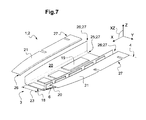
- FIG. 7 is a part perspective view, from above and oriented front at left side and aft at right side, of another embodiment of subfloor structure according to the invention, with two appending upper external extensions mechanically attached a posteriori to the construction of an integral subfloor bowl hull made as a single-pieced of light metal alloy or composite.
- a first direction X referred to as “longitudinal” direction, to which reference is made as of the front / back locating of the structures described. Typically, in an aircraft, this corresponds to the roll axis. Terms such as front/rear are relative thereto.
- Another direction Y is referred to as being “transverse”, and is referred to as of the side or lateral locating of the structures described. The terms “side” or “left” / "right” are relative thereto.
- the Figure 1 shows in a schematic view a rotary wing aircraft 1 comprising an airframe 2 and a subfloor structure 3.
- the subfloor structure 3 is arranged between a floor surface 4 and an outer loft 5 of the airframe 2 of the rotary wing aircraft 1 below the floor surface 4.
- the invention is e.g. dedicated to aircrafts 1 like the one of Figure 1 .
- the subfloor structure 3 comprises a bottom shell 16 and a framework 15, wherein the construction framework 15 is arranged inside the bottom shell 16.
- the Figure 3 shows that the framework 15 and the bottom shell 16 are denoted as separate parts of the subfloor structure 3.
- the access openings 6 and the opening covers 7 are shown explicitly.
- the bottom shell 16 is a single part consisting of the substantially flat central bottom portion 23 and the two side curved portions 22 with the access openings 6.
- the bottom shell 16 comprises a sandwich design with monolithic regions all along the joining areas to its attachment to the framework 15.
- the framework 15 fits into the bottom shell 16, wherein the outer panels 13 and the inner panels 14 cover the framework 15, wherein the mainframes 11 protrude beyond the floor surface in a vertical direction.
- the terms and expressions as at least locally extending have to be understood in a broad manner.
- the general extending indicates an overall direction along which the item is extending, but of course do comprises embodiments where items of the subfloor structure 3 are locally bent or diverging from a pure longitudinal / transverse / elevational direction.
- the structures corresponding to longerons 8 are shown as substantially so-called vertical webs 20 having similar function than the separated and further added longerons 8.
- a subfloor bowl hull 18 comprises thereby the substantially flat portion of the bottom shell 16 and the substantially vertical webs 20, both primary load carrying parts.
- Two substantially vertical webs 20 are foreseen, one at each side of the flat portion of the bottom shell 16.
- the substantially vertical webs, called upward web portions 20, are starting to extend in a substantially perpendicular direction from the lower part of the bottom shell 16, towards a floor surface 4 with floor panels (13, 14 / 21) of the aircraft 1.
- the angle between the substantially flat portion of the bottom shell and the substantially vertical webs and the floor surface can be between 80° and 130°.
- the so-called vertical webs 20 are e.g. integrally formed on both longitudinally extending sides of the bottom shell 16, in particular from both sides of the substantially flat and horizontally extending portion of the bottom shell 16. Thereby the bottom shell 16 and the vertical webs 20 can span the main longitudinal extending portion of the subfloor structure.
- the substantially vertical webs can take over hereby the functionality of the longerons in the subfloor structure 3. Between the substantially vertical webs and the bottom shell a material and structural continuity can be advantageously realized.
- the load carrying parts of the subfloor structure 3 can thereby be improved by avoiding stress concentration. Possible sources of failure can thereby be eliminated.
- a lower edge radius between the transition from the substantially flat bottom shell 16 and the substantially vertical webs of the upward web portions 20 can act as a trigger function within the vertical portion of the subfloor bowl hull 18 during a crash and can be varied.
- the longitudinal discrete kinks locations 12 are shown, wherein the trajectory of the respective longerons 8 is tilted inwards in order to adapt the framework 15 to the outer aircraft loft 5.
- An inner rib 10 is arranged coincident to the discrete kink location 12 to provide for adequate support and to react the discrete deflection of the load path of the longeron 8.
- the Figure 3 shows a subfloor structure 3 according to the invention that comprises a "hat-shaped" subfloor bowl hull 18, inner ribs 10 and outer ribs 9 for crossbeams, and two outer side shells 17 with access openings 6.
- the subfloor bowl hull 18 comprises a bottom central portion 23, upward webs portions 20, and integrated upper external extensions 21.
- the subfloor bowl shell 18 is one single integral part, with the bottom central portion 23, the webs 20 and the extensions 21 being integrally formed.
- the outer side portions 17 are shells close the contour of the hull 18, at its sides.
- the outer side portions 17 are secondary structural elements which are attached to the subfloor bowl hull 18 at a lateral transition area (transition region 25) from the bottom central portion 23 with the webs 20, to the outer lateral borders of the extensions 21 and to the outer ribs 9.
- the rigid attachment of the various structural items (e.g. 9, 10, 11, 17, and 21) to the hull 18 are designated as mechanical fastening means and shown in 27 on the figures 3 and 5 .
- the inner ribs 10 are arranged inside the subfloor bowl hull 18 between the webs 20, and are attached to the webs 20 and to the bottom central portion 23.
- the bottom central portion 23 of the hull 18 shows a flat lateral extension and a slight outwardly convex curvature along the longitudinal direction X, from the front to the back of the aircraft 1.
- the extensions 21 comprise cut-outs to house the main frames 11.
- An inner floor panel 14 is attached on top of the inner ribs 10, the lateral outer borders being attached to the webs 20 by mechanical fastening means 27.
- each extension 21 is formed as a separate part that is connected to U-shaped subfloor bowl hull 18 comprising the bottom central portion 23 and the webs 20.
- the extensions 21 of this embodiment are attached in this embodiment, to the top end of the respective webs 20, by mechanical fastening means 27.
- the Figure 4 shows the subfloor bowl hull 18 that comprises the bottom central portion 23, the webs 20 and the extensions 21.
- the geometrical continuity of these three structural items of the bowl hull 18 is resulting from integration into a single, unitary piece (i.e. the hull 18).
- the continuous transition at the transition region 25 between the bottom central portion 23 and the webs 20, and the continuous transition at transitional locations 26 between the webs 20 and the extensions 21 show a radius corner.
- the hull 18 is continuous along the most part of an overall longitudinal dimension DX of the whole subfloor structure 3, in the longitudinal direction X and shows a sandwich design with monolithic regions all along the joining areas to the crossbeams and sandwich regions 19.
- no discrete kink location 12 is present along the trajectory of the webs 20.
- the main frames 11 are divided into central portions, which are allocated within the webs 20, and lateral portions which are allocated between the outer side portions 17 forming shells, and the webs 20.
- the Figure 5 shows that the trajectory of the webs 20 follows a smoothly curved shape, with no kinks.
- the trajectory of the webs 20 is denoted by the transitional locations 26 between the respective web 20 and the respective extension 21 or the top end of the web 20.
- the smooth curve shows a tangent continuity all along its length.
- the Figure 6 shows the subfloor bowl hull 18 of Figure 4 .
- the subfloor bowl hull 18 represents the core element of the subfloor structure 3.
- the hat-shaped (or reversed omega sign shape) integral design of the subfloor bowl hull 18 is denoting the bottom central portion 23, the webs 20 and the extensions 21 being all formed in one single piece.
- the subfloor bowl hull 18 comprises only primary structural elements, which are main load carrying parts.
- the lateral borders of the bottom central portion 23 merge into the webs 20 forming a continuous and smooth transition region 25 with a radius corner.
- the top borders of the webs 20 merge into the extensions 21 forming a continuous and smooth transitional location 26 with a radius corner.
- the subfloor bowl hull 18 is in the embodiment of Figure 4 , made of a composite material and cured in one single shot.
- the sandwiched areas 19, the monolithic areas and the cut-outs of the horizontal extensions of the hull 18 are shown on Figures 4 and 6 .
- the Figure 7 shows an embodiment of the integral subfloor bowl hull 18, being composed of a bottom central portion 23 and two upwards web portions 20, the lateral borders of the bottom central portion 23 merging into the corresponding webs 20 forming a continuously smooth lateral transitional location with a radius corner.
- the upper external portions 21 are separate parts, attached a posteriori to the upper borders of the webs 20.
- Mechanical fastening means 27 are making the integrated hull 18 and the upper external portions 21 rigidly attached together.
- the integral hull 18 is a single-pieced of composite.
- the hull 18 of Figure 7 is made of forged metal alloy, for instance of aluminium alloy e.g. obtained by forge working of a sheet of light metal alloy.
- each upper external portion 21 is thus initially constructed as separated parts. Then, each upper external portion 21 is attached at a corresponding upper connection area, i.e. another type of transitional location 26, to the upward web portions 20 of the subfloor bowl hull 18, by mechanical fastening means 27. This departs from the embodiments of Figures 3-6 where the upper external portions 21 are integral with the upward web portions 20 and therefore the whole subfloor bowl shell 18.
- the subfloor structure 3 of the invention comprises attachments for embarked payload, e.g. rail seats 24.
- Secondary element not main load carrying element
- Secondary elements e.g. outer ribs 9, inner ribs 10, main frames 11 and in embodiments the upper external extensions 21
- secondary joints less strength and reliability required
- the invention thus allows the longerons (primary elements) being integrated to the lower portion of the bottom shell 16 (primary element) resulting in an integral "bowl"-like structural element (the hull 18) which represents the main load carrying part within the subfloor structure 3.
- This design eliminates a primary attachment between the longerons 8 and the bottom central portion 23 of the shell.
- the secondary side shells (secondary elements e.g. outer side portions 17) of the bottom shell 16 can be designed as individual parts which are rigidly attached to the "bowl" element (hull 18) at its lower portion (23) by means of chemical bonding and / or physical fastening (the expression “mechanical fastening means 27" covers all these types of rigid attachment).
- means 27 includes: screwing, riveting, gluing, welding or the like. Since the outer side portions 17 are secondary elements, there are no strong requirements set on their attachment to the hull 18. This departs the invention from prior bottom shells that include in a single hull 18, both the bottom central portion 23 and the outer side portions 17.
- the integral subfloor bowl hull 18 of the invention shows in a first embodiment a substantially horizontal, flat bottom portion 23 - that corresponds to the lower shell portion of the subfloor structures of the art - and two substantially vertical webs 20 - that correspond to the longerons 8 of the art - extending from both lateral ends of the horizontal bottom shell portion.
- the lower edge radius at the transition from the lower shell portion and the vertical shell portions develops the trigger function within the vertical shell portions during a cash event.
- the upper longeron has upper caps which are integrated within the upward web portions 20 and lower caps are integrated to the bottom central portion 23 or its transition area to the webs 20.
- the floor surface 4 shows a central portion (panel 14) and lateral portion (panels 13) which are attached to the webs of the hull 18, the ribs, frames and the side shells.
- the lateral floor parts (panels 13) are fixed structural parts, whereas the central floor part (panel 14) is removable.
- the "bowl"-shell formed by the integral subfloor bowl hull 18 incorporates as well substantially horizontal elements (upper external extensions 21), extending outwards from the upper ends of both substantially vertical webs.
- These parts are structural components that continuously stabilize the webs and the upper caps of the integral longeron defined by the portions 20, allowing for a smooth, continuous and smeared deflection of the loads applied on the cap.
- the substantially horizontal portions 21 / extensions 21 are hence primary load bearing elements which increase at the same time the effective area moment of inertia and hence the bending stiffness of the subfloor structure 3.
- the substantially horizontal extensions are preferably at the same time the outer floor panels.
- a central, removable inner floor panel 14 is then mechanically attached by means 27, to the webs of the "bowl"-shell and to the ribs.
- the webs of the "bowl"-shell or hull 18 show a longitudinal trace progression described by a curve with tangential continuity all along their top ends (or, if having upper external extensions 21 at their upper ends, along the transition from the webs to the extensions).
- the main functions of load carrying in the subfloor structure 3 are allocated within one single part, the hull 18. This is useful, easy to obtain during manufacturing processes and effective using composite materials and leads to important structural simplifications as well as to a pronounced compatibility to specific composite-related manufacturing processes.
- the invention eliminates a localized intersectional kinks and the associated discrete deflection of the load path of the longerons which are integrated in webs 20 according to the invention, hence eliminating the associated stress intensities and the required additional fittings.
- Embodiments of the invention allow exploiting the advantages of composite materials, allowing a higher degree of structural integration and the production of non-developable surfaces.
- Integrating outer side extensions 21 acting as external outer floor panels 13 of the art
- Integrating outer side extensions 21 to the integral subfloor bowl hull 18 in the floor surface 4, as per embodiment of Figures 4-6 , eliminates another structural joint (that one needed to attach the lateral floor panels to the "bowl"-shell webs), hence leading to further structural advantages.
Abstract
Description
- The invention belongs to the overall technical class of aeronautics, and air transport.
- More precisely, the invention concerns the domain of aircraft structures. Among such aircraft structures, the invention relates to the technical field of constructional features of aircraft structures, such as frames, stringers, longerons, bulkheads, but also outer shells, fairings, covers or fuselage sections.
- Specifically, the invention proposes a subfloor structure for a rotary wing aircraft or rotorcraft, such as a helicopter.
- Before discussing the background of the invention, some terms are briefly defined.
- As per
Figure 1 , arotary wing aircraft 1 comprises anairframe 2, i.e. an aircraft structure that defines anouter loft 5, i.e. the aerodynamic envelope of the fuselage. Theairframe 2 is extended longitudinally and laterally aside an anteroposterior plane XZ of theaircraft 1. Such anaircraft 1 is having structural constructions, including asubfloor structure 3 at a lower part LP of theairframe 2. Arotary wing aircraft 1 also have one -or a plurality of-: rotors R, landing gear LG, and equipment. - Now referring to
Figure 2 , is discussed a typical background of the invention. - In a classical
rotary wing aircraft 1, asubfloor structure 3 is arranged within the lower part LP, between afloor surface 4 defining a cabin level and theouter loft 5. Typically, thesubfloor structure 3 comprises abottom shell 16,outer floor panels 13,inner floor panels 14 and aframework construction 15. Theframework construction 15 connects the floor panels 13-14 to thebottom shell 16. For typical aircrafts, thebottom shell 16 covers most of the surface of the lower part LP of theouter loft 5, below thefloor surface 4. Theframework construction 15 comprises interconnectedlongerons 8,outer ribs 9 andinner ribs 10, as well as the lower portion ofmain frames 11. - The
longerons 8 are structural and generally longitudinal beams being basically arranged side by side along the anteroposterior plane XZ. Thelongerons 8 are spanning the entire length of thesubfloor structure 3, whereas theouter ribs 9 andinner ribs 10 are forming crossbeams. - Such crossbeams are basically arranged orthogonally to the anteroposterior plane XZ and span the whole width of the
subfloor structure 3 at their respective location. Hence, theframework construction 15 adopts a somehow perpendicular grid configuration with numerous intersections, such as thediscrete kink locations 12. - Upwardly, both the
longerons 8 and the ribs 9-10 extend from thebottom shell 16 to thefloor surface 4 and feature basically flat stiffened webs. Eachlongeron 8 or rib 9-10 has respective caps, along the upper and lower perimeter of the corresponding flat stiffened web. - Typical in such architectures, a fore portion of the
longerons 8, proximal to the nose of thesubfloor structure 3, is tilted inwardly with respect to a longitudinal direction X of theaircraft 1, in order to adapt theconstruction framework 15 to theouter loft 5 that shows a smaller width close to the front (nose) of theaircraft 1. Thelongerons 8 are locally attached to respective ribs 9-10 at thediscrete kink locations 12, where the aft portion of thelongeron 8 is substantially in line with the longitudinal direction X. - The fore portion of the
longerons 8 is also upwardly slanted by a predetermined angle in the anteroposterior plane XZ, with respect to the longitudinal direction X. The caps being connected to the rib at thediscrete kink locations 12, this provides for adequate support of the caps of thelongerons 8, reacting the discrete deflection of the normal loads of the caps of thelongerons 8. Geometrically speaking, thelongerons 8 show a longitudinal trace progression described by two straight lines with no tangential continuity at their connection point. - At side portions of the
bottom shell 16, it is typical havingaccess openings 6, providing access to the systems / equipment integrated in the space between thelongerons 8 and these side portions. The side portions and an essentially flat lower portion of thebottom shell 16 are forming a single part in some knownairframes 2. In other knownairframes 2, the side portions of thebottom shell 16 are individual parts attached to the lower portion. Knownairframes 2 have abottom shell 16 made from composites.Such bottom shell 16 typically features a sandwich design with monolithic regions all along the joints connecting theconstruction framework 16 to thebottom shell 16. - The tasks of the
subfloor structure 3 are manifold. Atypical subfloor structure 3 takes on the one hand the payload efforts and the loads from the landing gear LG. Such asubfloor structure 3 also transmits these efforts and loads to themain frames 11 globally acting, for specific types of architectures, as a beam supported by the twomain frames 11. - On the other hand, most known
subfloor structures 3 house various systems / equipments (e.g. electrical, mechanical and armouring). Typically, in knownsubfloor structures 3 housing of systems / equipments is mostly located in lateral volumes enclosed laterally between thelongerons 8 and the side portions of thebottom shell 16. Close to the center of thebottom shell 16, on sides of the anteroposterior plane XZ, thelongerons 8 confine, together with corresponding crossbeams formed by the ribs 9-10, compartments for fuel tanks T. In such compartments, elastomeric bladders are installed. -
Known subfloor structures 3 further provide for substantial kinetic energy absorption in case of a crash scenario of therotary wing aircraft 1. Thelongerons 8 are beams working as main load carrying members. - So as to illustrate the prior art, citation is now made of published documents related to constructional features of aircraft structures. For disclosure statement, the documents are
US2007114331 ,US2005001093 andUS6427945 . - The document
US2007114331 describes a helicopter collapsible deck having at least one longitudinal member and at least one cross member, which extend respectively in a first and second direction intersecting at a point; the cross member is interrupted at the point of intersection. The deck also has an anchoring device for connecting the longitudinal member and the cross member at the point of intersection. The anchoring device has at least one local permanent deformation section lying in a plane crosswise to the deck and for dissipating the energy transmitted to the deck in the event of impact. - The document
US2005001093 describes an impact resistant structure of a helicopter, which includes: an energy absorber positioned under a floor of the helicopter and directly connected to a cabin frame of the helicopter. The energy absorber is arranged in accordance with a distribution of a ground reaction force on a general ground at a time of crash situation. Another aspect provides an energy absorber that includes: a plurality of independent hollow tubes of fiber reinforced composite material integrally formed by bundling only the hollow tubes. The hollow tubes are arranged so as to reduce a number of intersecting wall surfaces of the hollow tubes. - The document
US6427945 describes a subfloor structure of an aircraft airframe of a helicopter that includes longerons and crossbeams that intersect each other and are interconnected to form a grid that is fixedly attached to the floor and the bottom skin of the aircraft fuselage. Structural elements such as pyramid frustums and reinforcements are arranged on the beams. The longeron and the crossbeam have a trapezoidal cross-section open on the wider base side, closed by a spine web along the narrow side, and bounded laterally by inclined leg webs that extend downwardly from the spine web at an angle outwardly relative to each other. The subfloor structure grid effectively absorbs the energy of a crash impact having both axial or vertical as well as non-axial or lateral impact force components. - Although the prior art provides interesting techniques, technical problems remain unsolved and useful enhancements would be beneficial.
- In a few words, enhancing the efficiency of a rotorcraft subfloor structure in terms of structural weight, design complexity, assembly work, manufacturing and overall production costs is becoming more and more required. This is due e.g. to the increasing cruising speed available with modern rotorcraft, the upgrade of customer needs in terms of payload / passengers capacity, the expending demand for lighter / cleaner / safer / longer-ranged and more silent apparatuses. While these constraints are growing, the demand for more energy saving and long-lasting rotorcrafts also increases, in an antagonistic manner.
- Besides, some other relative drawbacks may derive from prior art, as exemplified hereafter.
- Both, the longerons and the bottom shell are frequently load carrying. A load proof connection between the lower longeron caps and the bottom shell is required. This connection is highly loaded in the fuel tank area due to the peeling load excited by the fuel inertia transverse pressure load. This load proof connection requires a high reliability and strength, high accuracy during the assembly process, high damage tolerance and adequate reparability. This load proof connection is hence defined by additional structural joints and the associated increase in structural complexity and production efforts in terms of e.g. tolerance management, quality assurance, assembly, sealing and production time. This finally translates to higher structural weight and production costs.
- The discrete deflection of the load of the longerons at the intersectional kink locations results in high local stress levels at the upper caps of the longerons in the connection area. The upper caps have then to be supported by the rib by means of additional brackets. This is hence increasing weight and structural complexity.
- Due to the numerous cut-outs at the lateral sides of the fairings in the lower shells, most integral shell designs with integrated side shells becomes quite ineffective in terms of mechanical performance and manufacturing costs. In this case, an additional secondary element - the side shell portions with cut-outs - is integrated to a primary element - the bottom shell portion. Meanwhile a primary element - the longerons - is attached to another primary element - the bottom shell portion - by means of a highly loaded structural connection. Facing the outstanding possibilities of composites materials allowing for high structural integrability, this technical solution is deemed ineffective in terms of weight and reliability. The most current prior art rotorcrafts having alternatively separate side shells attached to a separate lower cover shell part includes another joint in the structure hence increasing complexity, assembly and production costs.
- Due to the necessity to attach the longerons to the bottom shell, the bottom shell has to provide for monolithic areas along the attachment to the construction framework. Providing for monolithic areas within a sandwich shell would reduce the bending stiffness of the sandwich bay, and would increase the production time and complicate an automatic lay-up with automatic composite fibre placement techniques.
- In view of the above drawbacks, it is an aim of the invention to provide for a subfloor structure that simplifies the structural arrangement of main load bearing components, in order to improve the overall structural airframe efficiency in terms of weight and production costs. Should a composite subfloor structure be contemplated, this would take benefit of the design and manufacturing advantages of composite materials. But similar benefits may be reached with other construction methods such as forged integrated large-sized metal items, e.g. involving light alloys like aluminium alloys.
- Therefore, an object of the invention is to provide a subfloor structure avoiding, among others, most of the exposed drawbacks of the prior the art.
- In this purpose, based upon the teachings of the document
US6427945 , claimed objects are a subfloor structure and a rotary wing aircraft. - In an embodiment, the subfloor structure for a rotary wing aircraft is comprising: an airframe extended longitudinally and laterally aside an anteroposterior plane and including and delimiting the subfloor structure with an outer bottom shell, a construction framework, and floor panels defining a floor surface at least locally perpendicular to an elevation direction of the anteroposterior plane; the subfloor structure having a pair of longerons extending at least locally along the longitudinal axis and at least a pair of crossbeams defined by inner and outer ribs and at least locally extending along a transverse direction orthogonal to the anteroposterior plane; the outer bottom shell having a bottom central portion delimited transversally by the two longerons, the outer bottom shell further having at least a pair of outer side shells extending outwards aside the bottom central portion. The subfloor structure further comprises an integral subfloor bowl hull made of a U-shaped one-piece and defining at least: the bottom central portion, two lateral transition regions and two upward web portions; the upward web portions integrally extending from the bottom central portion by forming the two longerons and being integrated to the integral subfloor bowl hull together with the two lateral transition regions; the lateral transition regions being opposed one to the other relatively to the anteroposterior plane, each transition region being continuously merged with the bottom central portion and one of the two upward web portions; the outer side shells being attached to the integral subfloor bowl hull in the vicinity of the lateral transition regions.
- In an embodiment, the integral subfloor bowl hull is having at least a pair of upper external extensions each laterally extending from the upward web portions at least locally in a plane parallel to the floor surface, each of the upward web portions having a transitional location rigidly attached to the corresponding upper external extension, each transitional location being located proximal a top end portion of the corresponding upward web portion.
- In an embodiment, at least a pair of upper external extensions is formed integral with the subfloor bowl shell at the transitional locations, each corresponding upward web portion being attached to the corresponding upper external extension in a continuous merging into the adjacent horizontal extension at the corresponding transitional location by forming a continuous curved transition. Thus, the invention allows the outer floor panels to be obtained together with the subfloor bowl hull.
- In an embodiment, at least two upper external extensions are initially constructed as separated parts; each upper external extension is attached at a corresponding upper transitional location at a top end of the corresponding upward web portion of the integral subfloor bowl hull, by mechanical fastening means. Thus, the invention allows some outer floor panels to be replaced by the upper external extensions and to be easily jointed to the subfloor bowl hull.
- In an embodiment, each upward web portion extends upwardly from the bottom central portion of the subfloor bowl hull to a transitional location located proximal a top end portion of the upward web portion; the upward web portion extends at least locally parallel to the anteroposterior plane and the transitional location is extending atop the upward web portion, below the floor surface.
- In an embodiment, the integral subfloor bowl hull spans over at least 2/3 of an overall longitudinal dimension of the subfloor structure, below the floor surface. The one-pieced structure allows the invention to provide a highly integrated architecture, without major disruptions along the longitudinal direction, thus offering remarkable mechanical performance and reduced assembling work-load.
- In an embodiment, the subfloor structure incorporates a lower portion of at least two main frames; the main frames are attached to the integral subfloor bowl hull by mechanical fastening means.
- In an embodiment, the integral subfloor bowl hull is a single-piece made of a composite material; the subfloor bowl hull having the bottom central portion and the integrated upward web portions constructed in a one shot curing step. The one-pieced structure allows the invention to provide a highly integrated architecture, possibly further integrating the upward web portion in a single composite unit.
- In an embodiment, the integral subfloor bowl hull is made from a single-pieced of metal. The one-pieced structure allows the invention to provide a highly integrated architecture, possibly further integrating the upward web portion in a single metal-made unit, e.g. by forging.
- In an embodiment, the subfloor structure is having the horizontal extensions; the outer ribs forming crossbeams are attached to the subfloor bowl hull at an outer portion of the upward web portions and at a lower portion of the horizontal extensions, by mechanical fastening means. The invention thus allows offering remarkable mechanical performance and reduced assembling work-load for outer ribs of crossbeams.
- In an embodiment, the subfloor structure is having at least two upper external extensions above corresponding lateral transitional locations, each outer side shell being attached to the subfloor bowl hull in the vicinity of an outer portion of the lateral transitional location, to at least one outer rib forming a crossbeam and to a lower portion of the corresponding upper external extension, by mechanical fastening means. The invention thus allows offering remarkable mechanical performance and reduced assembling work-load for outer side shells.
- In an embodiment, at least one inner rib of a crossbeam is attached to an inner portion of the corresponding upward web portion and to an upper portion of the bottom central portion of the integral subfloor bowl hull, by mechanical fastening means. The invention thus allows offering remarkable mechanical performance and reduced assembling work-load for inner ribs of crossbeams.
- In an embodiment, the subfloor structure is having two upper external extensions flush with the floor plane; at least an inner floor panel being attached to an upper portion of the subfloor bowl hull, by mechanical fastening means; the two upper external extensions forming at least a part of outer floor panels. Thus, the invention allows easy obtaining of the floor surface, by easy adding of the inner panels and integrating of the outer floor panels, to the subfloor structure.
- In an embodiment, the lateral transition locate regions and the transitional locations each form a cross-sectional contour, the cross-sectional contour describing an all along, smooth and tangential continuity in a transverse plane perpendicular to a longitudinal direction of the subfloor structure. Thus, the invention avoids discrete load deflections.
- Another object of the invention is a rotary wing aircraft comprising an airframe and a subfloor structure as exposed above. The subfloor structure comprises at least one integral subfloor bowl hull with integrated upward web portions. The rotary wing aircraft is chosen among: helicopters, hybrid rotorcraft, UAV drone rotorcrafts.
- Non-limiting embodiments of the invention are described by way of examples, with reference to the accompanying drawings, including the following
figures 1-7 . - The
Figure 1 is a schematic side elevational view of a rotary wing aircraft, oriented front at left side and aft at right side ; the undercarriage or other structural items of the rotorcraft like the geometrical floor surface are illustrated as schematic box just for allowing an overall location. - The
Figure 2 is a part perspective view, with exploded structural items, of a non claimed subfloor structure. - The
Figure 3 is a part perspective view, from above and oriented front at left side and aft at right side, of an embodiment of subfloor structure according to the invention, with two integrated upward web portions and two appending upper external extensions integrated into a single integral subfloor bowl hull. The outer side portion is attached to the integral hull by mechanical fastening means. - The
Figure 4 is a part perspective view, with exploded structural items, of an embodiment of subfloor structure according to the invention, with two integrated upward web portions and oriented front at left side and aft at right side. - The
Figure 5 is an upright part plan view from the above, showing an embodiment of a subfloor structure to the invention, with two integrated upward web portions and oriented front at left side and aft at right side. Thefigure 5 shows the overall longitudinal dimension of the subfloor structure. - The
Figure 6 is a perspective view, of an embodiment of an embodiment of single integral subfloor bowl hull for a subfloor structure according to the invention, forming a singled-piece of composite material with two integrated upward web portions and upward web portions, showed oriented front at left side and aft at right side. - The
Figure 7 is a part perspective view, from above and oriented front at left side and aft at right side, of another embodiment of subfloor structure according to the invention, with two appending upper external extensions mechanically attached a posteriori to the construction of an integral subfloor bowl hull made as a single-pieced of light metal alloy or composite. - In the following, throughout the figures equal features and objects as well as parts are referred to the same numerals.
- In examples, for defining in the invention 3D, three mutually orthogonal directions X, Y and Z, also called "axis", are depicted in
figures 2-9 . A first direction X, referred to as "longitudinal" direction, to which reference is made as of the front / back locating of the structures described. Typically, in an aircraft, this corresponds to the roll axis. Terms such as front/rear are relative thereto. Another direction Y is referred to as being "transverse", and is referred to as of the side or lateral locating of the structures described. The terms "side" or "left" / "right" are relative thereto. - Typically, in an aircraft, this corresponds to the pitch axis. Yet another direction Z, referred to as being "height", to which reference is made as of the elevation or upright dimension of the structures described. Typically, in an aircraft, this corresponds to the yaw axis. Terms such as "up" / "down" or "high" / "low" are relative thereto. The directions X, Y and Z define together a referential "XYZ". The directions X and Z define together an anteroposterior plane XZ of the
aircraft 1. - The
Figure 1 shows in a schematic view arotary wing aircraft 1 comprising anairframe 2 and asubfloor structure 3. Thesubfloor structure 3 is arranged between afloor surface 4 and anouter loft 5 of theairframe 2 of therotary wing aircraft 1 below thefloor surface 4. The invention is e.g. dedicated toaircrafts 1 like the one ofFigure 1 . - In classical rotorcrafts, e.g. like in
Figure 3 , thesubfloor structure 3 comprises abottom shell 16 and aframework 15, wherein theconstruction framework 15 is arranged inside thebottom shell 16. - The
Figure 3 shows that theframework 15 and thebottom shell 16 are denoted as separate parts of thesubfloor structure 3. Theaccess openings 6 and the opening covers 7 are shown explicitly. It can be seen, that thebottom shell 16 is a single part consisting of the substantially flatcentral bottom portion 23 and the two side curvedportions 22 with theaccess openings 6. Thebottom shell 16 comprises a sandwich design with monolithic regions all along the joining areas to its attachment to theframework 15. Theframework 15 fits into thebottom shell 16, wherein theouter panels 13 and theinner panels 14 cover theframework 15, wherein themainframes 11 protrude beyond the floor surface in a vertical direction. - In the following, the terms and expressions as at least locally extending have to be understood in a broad manner. The general extending indicates an overall direction along which the item is extending, but of course do comprises embodiments where items of the
subfloor structure 3 are locally bent or diverging from a pure longitudinal / transverse / elevational direction. - From the invention embodiments, the structures corresponding to
longerons 8 are shown as substantially so-calledvertical webs 20 having similar function than the separated and further addedlongerons 8. Asubfloor bowl hull 18 comprises thereby the substantially flat portion of thebottom shell 16 and the substantiallyvertical webs 20, both primary load carrying parts. Two substantiallyvertical webs 20 are foreseen, one at each side of the flat portion of thebottom shell 16. The substantially vertical webs, calledupward web portions 20, are starting to extend in a substantially perpendicular direction from the lower part of thebottom shell 16, towards afloor surface 4 with floor panels (13, 14 / 21) of theaircraft 1. The angle between the substantially flat portion of the bottom shell and the substantially vertical webs and the floor surface can be between 80° and 130°. The so-calledvertical webs 20 are e.g. integrally formed on both longitudinally extending sides of thebottom shell 16, in particular from both sides of the substantially flat and horizontally extending portion of thebottom shell 16. Thereby thebottom shell 16 and thevertical webs 20 can span the main longitudinal extending portion of the subfloor structure. The substantially vertical webs can take over hereby the functionality of the longerons in thesubfloor structure 3. Between the substantially vertical webs and the bottom shell a material and structural continuity can be advantageously realized. The load carrying parts of thesubfloor structure 3 can thereby be improved by avoiding stress concentration. Possible sources of failure can thereby be eliminated. A lower edge radius between the transition from the substantiallyflat bottom shell 16 and the substantially vertical webs of theupward web portions 20 can act as a trigger function within the vertical portion of thesubfloor bowl hull 18 during a crash and can be varied. - In a top view of a
classical subfloor structure 3, the longitudinaldiscrete kinks locations 12 are shown, wherein the trajectory of therespective longerons 8 is tilted inwards in order to adapt theframework 15 to theouter aircraft loft 5. Aninner rib 10 is arranged coincident to thediscrete kink location 12 to provide for adequate support and to react the discrete deflection of the load path of thelongeron 8. - The
Figure 3 shows asubfloor structure 3 according to the invention that comprises a "hat-shaped"subfloor bowl hull 18,inner ribs 10 andouter ribs 9 for crossbeams, and twoouter side shells 17 withaccess openings 6. Thesubfloor bowl hull 18 comprises a bottomcentral portion 23,upward webs portions 20, and integrated upperexternal extensions 21. Thesubfloor bowl shell 18 is one single integral part, with the bottomcentral portion 23, thewebs 20 and theextensions 21 being integrally formed. Theouter side portions 17 are shells close the contour of thehull 18, at its sides. Theouter side portions 17 are secondary structural elements which are attached to thesubfloor bowl hull 18 at a lateral transition area (transition region 25) from the bottomcentral portion 23 with thewebs 20, to the outer lateral borders of theextensions 21 and to theouter ribs 9. The rigid attachment of the various structural items (e.g. 9, 10, 11, 17, and 21) to thehull 18 are designated as mechanical fastening means and shown in 27 on thefigures 3 and5 . Theinner ribs 10 are arranged inside thesubfloor bowl hull 18 between thewebs 20, and are attached to thewebs 20 and to the bottomcentral portion 23. The bottomcentral portion 23 of thehull 18 shows a flat lateral extension and a slight outwardly convex curvature along the longitudinal direction X, from the front to the back of theaircraft 1. - The
extensions 21 comprise cut-outs to house the main frames 11. - An
inner floor panel 14 is attached on top of theinner ribs 10, the lateral outer borders being attached to thewebs 20 by mechanical fastening means 27. - In a further embodiment (shown on
Figure 7 ), eachextension 21 is formed as a separate part that is connected to U-shapedsubfloor bowl hull 18 comprising the bottomcentral portion 23 and thewebs 20. Theextensions 21 of this embodiment are attached in this embodiment, to the top end of therespective webs 20, by mechanical fastening means 27. - The
Figure 4 shows thesubfloor bowl hull 18 that comprises the bottomcentral portion 23, thewebs 20 and theextensions 21. The geometrical continuity of these three structural items of thebowl hull 18 is resulting from integration into a single, unitary piece (i.e. the hull 18). The continuous transition at thetransition region 25 between the bottomcentral portion 23 and thewebs 20, and the continuous transition attransitional locations 26 between thewebs 20 and theextensions 21 show a radius corner. FromFigure 5 , is shown that thehull 18 is continuous along the most part of an overall longitudinal dimension DX of thewhole subfloor structure 3, in the longitudinal direction X and shows a sandwich design with monolithic regions all along the joining areas to the crossbeams andsandwich regions 19. UnlikeFigure 2 , nodiscrete kink location 12 is present along the trajectory of thewebs 20. Themain frames 11 are divided into central portions, which are allocated within thewebs 20, and lateral portions which are allocated between theouter side portions 17 forming shells, and thewebs 20. - The
Figure 5 shows that the trajectory of thewebs 20 follows a smoothly curved shape, with no kinks. The trajectory of thewebs 20 is denoted by thetransitional locations 26 between therespective web 20 and therespective extension 21 or the top end of theweb 20. The smooth curve shows a tangent continuity all along its length. - The
Figure 6 shows thesubfloor bowl hull 18 ofFigure 4 . Thesubfloor bowl hull 18 represents the core element of thesubfloor structure 3. The hat-shaped (or reversed omega sign shape) integral design of thesubfloor bowl hull 18 is denoting the bottomcentral portion 23, thewebs 20 and theextensions 21 being all formed in one single piece. Thesubfloor bowl hull 18 comprises only primary structural elements, which are main load carrying parts. The lateral borders of the bottomcentral portion 23 merge into thewebs 20 forming a continuous andsmooth transition region 25 with a radius corner. The top borders of thewebs 20 merge into theextensions 21 forming a continuous and smoothtransitional location 26 with a radius corner. Thesubfloor bowl hull 18 is in the embodiment ofFigure 4 , made of a composite material and cured in one single shot. The sandwichedareas 19, the monolithic areas and the cut-outs of the horizontal extensions of thehull 18 are shown onFigures 4 and6 . - The
Figure 7 shows an embodiment of the integralsubfloor bowl hull 18, being composed of a bottomcentral portion 23 and twoupwards web portions 20, the lateral borders of the bottomcentral portion 23 merging into the correspondingwebs 20 forming a continuously smooth lateral transitional location with a radius corner. Unlike onfigures 4-6 , the upperexternal portions 21 are separate parts, attached a posteriori to the upper borders of thewebs 20. Mechanical fastening means 27 are making theintegrated hull 18 and the upperexternal portions 21 rigidly attached together. - In the embodiment of
Figure 7 , theintegral hull 18 is a single-pieced of composite. In other embodiments, thehull 18 ofFigure 7 is made of forged metal alloy, for instance of aluminium alloy e.g. obtained by forge working of a sheet of light metal alloy. - In the
subfloor structure 3 ofFigure 7 , the pair of upperexternal portions 21 is thus initially constructed as separated parts. Then, each upperexternal portion 21 is attached at a corresponding upper connection area, i.e. another type oftransitional location 26, to theupward web portions 20 of thesubfloor bowl hull 18, by mechanical fastening means 27. This departs from the embodiments ofFigures 3-6 where the upperexternal portions 21 are integral with theupward web portions 20 and therefore the wholesubfloor bowl shell 18. - The
subfloor structure 3 of the invention comprises attachments for embarked payload, e.g. rail seats 24. - Here are mentioned some of the principles of the invention.
- The integration of a secondary element (secondary element = not main load carrying element) to a primary element is less effective than the integration - e.g. in a subfloor bowl hull 18 - of a primary element (primary element=main load carrying element,
e.g. web portions 20 acting likelongerons 8, part ofbottom shell 16 defined by the bottomcentral portion 23 and in embodiments the upper external extensions 21) to another primary element, since a main structural joint and all of the associated drawbacks and challenges are then eliminated. Doing so, the structural reliability, robustness and weight efficiency are increased. Secondary elements (e.g.outer ribs 9,inner ribs 10,main frames 11 and in embodiments the upper external extensions 21) can be then attached by secondary joints (less strength and reliability required) to the primary integral element. The invention thus allows the longerons (primary elements) being integrated to the lower portion of the bottom shell 16 (primary element) resulting in an integral "bowl"-like structural element (the hull 18) which represents the main load carrying part within thesubfloor structure 3. This design eliminates a primary attachment between thelongerons 8 and the bottomcentral portion 23 of the shell. With the invention, the secondary side shells (secondary elements e.g. outer side portions 17) of thebottom shell 16 can be designed as individual parts which are rigidly attached to the "bowl" element (hull 18) at its lower portion (23) by means of chemical bonding and / or physical fastening (the expression "mechanical fastening means 27" covers all these types of rigid attachment). For instance, means 27 includes: screwing, riveting, gluing, welding or the like. Since theouter side portions 17 are secondary elements, there are no strong requirements set on their attachment to thehull 18. This departs the invention from prior bottom shells that include in asingle hull 18, both the bottomcentral portion 23 and theouter side portions 17. - The integral
subfloor bowl hull 18 of the invention shows in a first embodiment a substantially horizontal, flat bottom portion 23 - that corresponds to the lower shell portion of the subfloor structures of the art - and two substantially vertical webs 20 - that correspond to thelongerons 8 of the art - extending from both lateral ends of the horizontal bottom shell portion. There is a material and structural continuity between the load carrying bottom shell portion and the webs hence eliminating stress concentrations and possible sources of failure. The lower edge radius at the transition from the lower shell portion and the vertical shell portions develops the trigger function within the vertical shell portions during a cash event. The upper longeron has upper caps which are integrated within theupward web portions 20 and lower caps are integrated to the bottomcentral portion 23 or its transition area to thewebs 20. In this configuration, thefloor surface 4 shows a central portion (panel 14) and lateral portion (panels 13) which are attached to the webs of thehull 18, the ribs, frames and the side shells. In embodiments, the lateral floor parts (panels 13) are fixed structural parts, whereas the central floor part (panel 14) is removable. - In an embodiment of the invention, the "bowl"-shell formed by the integral
subfloor bowl hull 18 incorporates as well substantially horizontal elements (upper external extensions 21), extending outwards from the upper ends of both substantially vertical webs. These parts are structural components that continuously stabilize the webs and the upper caps of the integral longeron defined by theportions 20, allowing for a smooth, continuous and smeared deflection of the loads applied on the cap. - The substantially
horizontal portions 21 /extensions 21 are hence primary load bearing elements which increase at the same time the effective area moment of inertia and hence the bending stiffness of thesubfloor structure 3. The substantially horizontal extensions are preferably at the same time the outer floor panels. In an embodiment, a central, removableinner floor panel 14 is then mechanically attached bymeans 27, to the webs of the "bowl"-shell and to the ribs. - A discrete deflection of the longeron's load of the art is eliminated, where contrary to the design as per the invention, stress concentrations do arise at one single
discrete kink location 12. - Geometrically speaking, the webs of the "bowl"-shell or
hull 18 show a longitudinal trace progression described by a curve with tangential continuity all along their top ends (or, if having upperexternal extensions 21 at their upper ends, along the transition from the webs to the extensions). - The main functions of load carrying in the
subfloor structure 3 are allocated within one single part, thehull 18. This is useful, easy to obtain during manufacturing processes and effective using composite materials and leads to important structural simplifications as well as to a pronounced compatibility to specific composite-related manufacturing processes. - Further parts like supporting outer ribs, inner ribs and main frames are attached to the webs and bottom part of the integral
subfloor bowl hull 18 or "bowl"-shell. - Here are mentioned some advantages of the invention.
- Two primary, main load-carrying elements of the art - the
longerons 8 and the bottomcentral portion 23 of the bottom shell 16 - are integrated within a single part (hull 18). This eliminates the need of structural, primary joints between them. - This translates to a better performance and improved reliability, robustness and weight efficiency, since there is no additional source of failure (joints are structural discontinuities which excite interruptions of the load path and hence stress intensities which can initiate structural failure) and no additional need of inspection and assembly.
- The invention eliminates a localized intersectional kinks and the associated discrete deflection of the load path of the longerons which are integrated in
webs 20 according to the invention, hence eliminating the associated stress intensities and the required additional fittings. - Load bearing horizontal extensions increase the bending stiffness of the
subfloor structure 3. - Embodiments of the invention allow exploiting the advantages of composite materials, allowing a higher degree of structural integration and the production of non-developable surfaces.
- Integrating outer side extensions 21 (acting as external
outer floor panels 13 of the art) to the integralsubfloor bowl hull 18 in thefloor surface 4, as per embodiment ofFigures 4-6 , eliminates another structural joint (that one needed to attach the lateral floor panels to the "bowl"-shell webs), hence leading to further structural advantages. - Now, for clarity purposes, is a listing of alphanumeric references of various items shown in the Figures.
Table 1 : Reference list. REFERENCE DESIGNATION X Longitudinal Axis Y Transverse Axis Z Elevation Axis XZ Anteposterior Plane LG Landing gear R Rotors LP Lower part of airframe T Fuel tanks DX Overall longitudinal dimension (3) 1 Rotary wing aircraft 2 Airframe 3 Subfloor structure 4 Floor surface 5 Outer loft (Aerodynamic envelope) 6 Access opening 7 Removable Cover 8 Longeron 9 Outer rib of crossbeam 10 Inner rib of crossbeam 11 Main Frame 12 Discrete kink locations 13 Outer floor panel 14 Inner floor panel 15 Framework construction 16 Bottom shell 17 Outer side portion 18 Integral subfloor bowl hull 19 Sandwich region 20 Upward web portions 21 Upper external extensions 22 Side curved portion 23 Bottom central portion 24 Seat Rails 25 Transition region 26 Transitional locations 27 Mechanical fastening means
Claims (15)
- Subfloor structure (3) for a rotary wing aircraft (1), the rotary wing aircraft (1) comprising: an airframe (2) extended along an anteroposterior plane (XZ), including and delimiting the subfloor structure (3) with an outer bottom shell (16), a construction framework (15), and floor panels (13-14) defining a floor surface (4) at least locally perpendicular to an elevation direction (Z) of the anteroposterior plane (XZ) ; the subfloor structure (3) having a pair of longerons (8) extending at least locally along the longitudinal axis (X) and at least a pair of crossbeams defined by inner and outer ribs (9-10) and at least locally extending along a transverse direction (Y) orthogonal to the anteroposterior plane (XZ), the outer bottom shell (16) having a bottom central portion (23) delimited transversally by the two longerons (8), the outer bottom shell (16) further having at least a pair of outer side shells (17) extending outwards aside the bottom central portion (23);
characterized in that the subfloor structure (3) comprises an integral subfloor bowl hull (18) made of a U-shaped one-piece and defining at least: the bottom central portion (23), two lateral transition regions (25) and two upward web portions (20); the upward web portions (20) integrally extending from the bottom central portion (23) by forming the two longerons (8) and being integrated to the integral subfloor bowl hull (18) together with the two lateral transitional locations (25); the lateral transition regions (25) being opposed one to the other relatively to the anteroposterior plane (XZ), each transition region (25) being continuously merged with the bottom central portion (23) and one of the two upward web portions (20), the outer side shells (17) being attached to the integral subfloor bowl hull (18) in the vicinity of the lateral transition regions (25). - Subfloor structure (3) of claim 1,
characterized in that the integral subfloor bowl hull (18) is having at least a pair of upper external extensions (21) each laterally extending from the upward web portions (20) at least locally in a plane parallel to the floor surface (4), each of the upward web portions (20) having a transitional location (26) rigidly attached to the corresponding upper external extension (21), each transitional location (26) being located proximal a top end portion of the corresponding upward web portion (20). - Subfloor structure (3) of claim 2,
characterized in that at least a pair of upper external extensions (21) is formed integral with the subfloor bowl shell (18) at the transitional locations (26), each corresponding upward web portion (20) being attached to the corresponding upper external extension (21) in a continuous merging into the adjacent horizontal extension (21) at the corresponding transitional locations (26) by forming a continuous curved transition. - Subfloor structure (3) of claim 2,
characterized in that at least a pair of upper external extensions (21) are initially constructed as separated parts, each upper external extension (21) is attached at a corresponding upper transitional location (26) at a top end of the corresponding upward web portion (20) of the integral subfloor bowl hull (18), by mechanical fastening means (27). - Subfloor structure (3) of claim 1,
characterized in that each upward web portion (20) extends upwardly from the bottom central portion (23) of the subfloor bowl hull (18) to a transitional location (26) located proximal a top end portion of the upward web portion (20); the upward web portion (20) extends at least locally parallel to the anteroposterior plane (XZ) and the transitional location (26) is extending atop the upward web portion (20), below the floor surface (4). - Subfloor structure (3) of claim 1,
characterized in that the integral subfloor bowl hull (18) spans over at least 2/3 of an overall longitudinal dimension (DX) of the subfloor structure (3), below the floor surface (4). - Subfloor structure (3) of claim 1,
characterized in that the subfloor structure (3) incorporates a lower portion of at least two main frames (11) ; the main frames (11) are attached to the integral subfloor bowl hull (18) by mechanical fastening means (27). - Subfloor structure (3) of claim 1,
characterized in that the integral subfloor bowl hull (18) is a single-piece made of a composite material, the subfloor bowl hull (18) having the bottom central portion (23) and the integrated upward web portions (20) constructed in a one shot curing step. - Subfloor structure (3) of claim 1,
characterized in that the integral subfloor bowl hull (18) is made from a single-pieced of metal. - Subfloor structure (3) of claim 1 ,
characterized in that the subfloor structure (3) having the horizontal extensions (21); the outer ribs (9) forming crossbeams are attached to the subfloor bowl hull (18) at an outer portion of the upward web portions (20) and at a lower portion of the horizontal extensions (21), by mechanical fastening means (27). - Subfloor structure (3) of claim 1,
characterized in that, the subfloor structure (3) having at least two upper external extensions (21) above corresponding lateral transition regions (25), each outer side shell (17) is attached to the subfloor bowl hull (18) in the vicinity of an outer portion of the lateral transition region (25), to at least one outer rib (9) forming a crossbeam and to a lower portion of the corresponding upper external extension (21), by mechanical fastening means (27). - Subfloor structure (3) of claim 1,
characterized in that at least one inner rib (10) of a crossbeam is attached to an inner portion of the corresponding upward web portion (20) and to an upper portion of the bottom central portion (23) of the integral subfloor bowl hull (18), by mechanical fastening means (27). - Subfloor structure (3) of claim 1,
characterized in that, the subfloor structure (3) is having two upper external extensions (21) flush with the floor plane (4); at least an inner floor panel (14) attached to an upper portion of the subfloor bowl hull (18), by mechanical fastening means (27); the two upper external extensions (21) forming at least a part of outer floor panels (13). - Subfloor structure (3) of claim 1,
characterized in that the lateral transition regions (25) and the transitional locations (26) each form a cross-sectional contour, the cross-sectional contour describing an all along, smooth and tangential continuity in a transverse plane perpendicular to a longitudinal direction (X) of the subfloor structure (3). - A rotary wing aircraft (1) comprising an airframe (2) and a subfloor structure (3) according to claim 1, wherein the subfloor structure (3) comprises at least one integral subfloor bowl hull (18) with integrated upward web portions (20);
characterized in that the rotary wing aircraft (1) is chosen among : helicopters, hybrid rotorcraft, UAV drone rotorcrafts.
Priority Applications (5)
| Application Number | Priority Date | Filing Date | Title |
|---|---|---|---|
| EP13400042.1A EP2889212B1 (en) | 2013-12-30 | 2013-12-30 | Subfloor structure with an integral hull for a rotary wing aircraft |
| US14/578,653 US9688381B2 (en) | 2013-12-30 | 2014-12-22 | Subfloor structure with an integral hull for a rotary wing aircraft |
| KR1020140188704A KR101972404B1 (en) | 2013-12-30 | 2014-12-24 | Subfloor structure with an integral hull for a rotary wing aircraft |
| KR1020170103774A KR20170096623A (en) | 2013-12-30 | 2017-08-16 | Subfloor structure with an integral hull for a rotary wing aircraft |
| KR1020180045157A KR20180041654A (en) | 2013-12-30 | 2018-04-18 | Subfloor structure with an integral hull for a rotary wing aircraft |
Applications Claiming Priority (1)
| Application Number | Priority Date | Filing Date | Title |
|---|---|---|---|
| EP13400042.1A EP2889212B1 (en) | 2013-12-30 | 2013-12-30 | Subfloor structure with an integral hull for a rotary wing aircraft |
Publications (2)
| Publication Number | Publication Date |
|---|---|
| EP2889212A1 true EP2889212A1 (en) | 2015-07-01 |
| EP2889212B1 EP2889212B1 (en) | 2016-01-06 |
Family
ID=50151068
Family Applications (1)
| Application Number | Title | Priority Date | Filing Date |
|---|---|---|---|
| EP13400042.1A Active EP2889212B1 (en) | 2013-12-30 | 2013-12-30 | Subfloor structure with an integral hull for a rotary wing aircraft |
Country Status (3)
| Country | Link |
|---|---|
| US (1) | US9688381B2 (en) |
| EP (1) | EP2889212B1 (en) |
| KR (3) | KR101972404B1 (en) |
Families Citing this family (3)
| Publication number | Priority date | Publication date | Assignee | Title |
|---|---|---|---|---|
| EP3584151B1 (en) | 2018-06-20 | 2021-01-27 | AIRBUS HELICOPTERS DEUTSCHLAND GmbH | A modular subfloor arrangement for an aircraft |
| WO2021171633A1 (en) * | 2020-02-29 | 2021-09-02 | 株式会社エアロネクスト | Frame assembly and method for manufacturing same |
| CN112478126B (en) * | 2020-12-02 | 2024-01-02 | 中国航空工业集团公司沈阳飞机设计研究所 | Unmanned aerial vehicle fuselage cabin section |
Citations (4)
| Publication number | Priority date | Publication date | Assignee | Title |
|---|---|---|---|---|
| US6427945B1 (en) | 1999-05-14 | 2002-08-06 | Eurocopter Deutschland Gmbh | Subfloor structure of an aircraft airframe |
| US20050001093A1 (en) | 2002-12-04 | 2005-01-06 | Kawasaki Jukogyo Kabushiki Kaisha | Impact resistant structure for the helicopter and energy absorber used for the same |
| US20070114331A1 (en) | 2005-10-21 | 2007-05-24 | Stefano Poggi | Helicopter collapsible deck |
| US20120112004A1 (en) * | 2009-07-17 | 2012-05-10 | Atsumi Tanaka | Shock absorbing structure |
Family Cites Families (11)
| Publication number | Priority date | Publication date | Assignee | Title |
|---|---|---|---|---|
| DE3401189A1 (en) * | 1983-01-25 | 1984-07-26 | Westland PLC, Yeovil, Somerset | COMPOSITE HELICOPTER FUSELAGE |
| US4593870A (en) * | 1983-09-09 | 1986-06-10 | Bell Helicopter Textron Inc. | Energy absorbing composite aircraft structure |
| US5069318A (en) | 1989-12-26 | 1991-12-03 | Mcdonnell Douglas Corporation | Self-stabilized stepped crashworthy stiffeners |
| FR2693976B1 (en) * | 1992-07-22 | 1994-09-30 | Eurocopter France | Fuselage structure for helicopter. |
| AU2003258443A1 (en) | 2002-09-15 | 2004-04-30 | Rcc Regional Compact Car Ag | Structural component consisting of fibre-reinforced thermoplastic |
| US8869673B2 (en) * | 2006-01-31 | 2014-10-28 | Sikorsky Aircraft Corporation | Structural panel with ballistic protection |
| DE102006025388B4 (en) * | 2006-05-31 | 2009-10-29 | Airbus Deutschland Gmbh | Line system arrangement for use in fuselage of e.g. aircraft, has receiving region for receiving component of line system, and adapted to internal pressure which corresponds to particular external pressure of fuselage |
| DE102006026168A1 (en) * | 2006-06-06 | 2008-01-31 | Airbus Deutschland Gmbh | Aircraft fuselage structure and method for its manufacture |
| US8079549B2 (en) * | 2008-06-30 | 2011-12-20 | EMBRAER—Empresa Brasileira de Aeronautica S.A. | Monolithic integrated structural panels especially useful for aircraft structures |
| JP5237355B2 (en) * | 2010-11-26 | 2013-07-17 | 三菱重工業株式会社 | Method for manufacturing panel structure |
| FR2979896A1 (en) * | 2011-09-08 | 2013-03-15 | Airbus Operations Sas | AIRCRAFT FUSELAGE FRAME ELEMENT |
-
2013
- 2013-12-30 EP EP13400042.1A patent/EP2889212B1/en active Active
-
2014
- 2014-12-22 US US14/578,653 patent/US9688381B2/en active Active
- 2014-12-24 KR KR1020140188704A patent/KR101972404B1/en active IP Right Grant
-
2017
- 2017-08-16 KR KR1020170103774A patent/KR20170096623A/en active Application Filing
-
2018
- 2018-04-18 KR KR1020180045157A patent/KR20180041654A/en active Application Filing
Patent Citations (4)
| Publication number | Priority date | Publication date | Assignee | Title |
|---|---|---|---|---|
| US6427945B1 (en) | 1999-05-14 | 2002-08-06 | Eurocopter Deutschland Gmbh | Subfloor structure of an aircraft airframe |
| US20050001093A1 (en) | 2002-12-04 | 2005-01-06 | Kawasaki Jukogyo Kabushiki Kaisha | Impact resistant structure for the helicopter and energy absorber used for the same |
| US20070114331A1 (en) | 2005-10-21 | 2007-05-24 | Stefano Poggi | Helicopter collapsible deck |
| US20120112004A1 (en) * | 2009-07-17 | 2012-05-10 | Atsumi Tanaka | Shock absorbing structure |
Non-Patent Citations (1)
| Title |
|---|
| "COMPOSITES SOFTEN IMPACT", FLIGHT INTERNATIONAL, REED BUSINESS INFORMATION, SUTTON SURREY, GB, vol. 167, no. 4982, 26 April 2005 (2005-04-26), pages 26, XP001227208, ISSN: 0015-3710 * |
Also Published As
| Publication number | Publication date |
|---|---|
| KR20180041654A (en) | 2018-04-24 |
| US20150183505A1 (en) | 2015-07-02 |
| US9688381B2 (en) | 2017-06-27 |
| EP2889212B1 (en) | 2016-01-06 |
| KR20150079431A (en) | 2015-07-08 |
| KR20170096623A (en) | 2017-08-24 |
| KR101972404B1 (en) | 2019-04-25 |
Similar Documents
| Publication | Publication Date | Title |
|---|---|---|
| US9688382B2 (en) | Method of constructing a fixed-wing aircraft | |
| KR102073995B1 (en) | Apparatus and methods for joining composite structures of aircrafts | |
| US9708065B2 (en) | Crown cabin configuration for an aircraft | |
| US8322656B2 (en) | Wing-fuselage section of an aircraft | |
| US10343768B2 (en) | Landing gear well roof | |
| US9108718B2 (en) | Composite-material structure and aircraft main wing and aircraft fuselage provided with the same | |
| US9896181B2 (en) | Aircraft rear structure | |
| US20130236692A1 (en) | Composite material structure, and aircraft wing and aircraft fuselage provided therewith | |
| CN101977811B (en) | Fuselage structure for aircraft | |
| US20190112034A1 (en) | Aircraft landing gear bay roof comprising an inclined aft bulkhead | |
| EP2591996A1 (en) | Elliptical fuselage with wing to body volume integrated in pressurised cabin | |
| US9688381B2 (en) | Subfloor structure with an integral hull for a rotary wing aircraft | |
| US9517831B2 (en) | Rotary wing aircraft airframe | |
| CN115535211A (en) | Aircraft and method of manufacturing an aircraft | |
| CN106507751B (en) | SUAV fuselage | |
| US20170066518A1 (en) | Aircraft rear portion comprising a vertical stabilizer having a box-section structure including a lower portion accommodated in the fuselage | |
| CN114802698A (en) | Joint for connecting a center wing box and a compartment in an aircraft | |
| CN114906313B (en) | Connection structure of aircraft fin and fuselage | |
| CN102849218A (en) | Mounting beam for auxiliary power unit of aircraft | |
| RU2481243C1 (en) | Aircraft wing and outer wing joint assembly | |
| CN219927960U (en) | High-safety light composite ventral fin structure |
Legal Events
| Date | Code | Title | Description |
|---|---|---|---|
| PUAI | Public reference made under article 153(3) epc to a published international application that has entered the european phase |
Free format text: ORIGINAL CODE: 0009012 |
|
| 17P | Request for examination filed |
Effective date: 20131230 |
|
| AK | Designated contracting states |
Kind code of ref document: A1 Designated state(s): AL AT BE BG CH CY CZ DE DK EE ES FI FR GB GR HR HU IE IS IT LI LT LU LV MC MK MT NL NO PL PT RO RS SE SI SK SM TR |
|
| AX | Request for extension of the european patent |
Extension state: BA ME |
|
| R17P | Request for examination filed (corrected) |
Effective date: 20150728 |
|
| RBV | Designated contracting states (corrected) |
Designated state(s): AL AT BE BG CH CY CZ DE DK EE ES FI FR GB GR HR HU IE IS IT LI LT LU LV MC MK MT NL NO PL PT RO RS SE SI SK SM TR |
|
| GRAP | Despatch of communication of intention to grant a patent |
Free format text: ORIGINAL CODE: EPIDOSNIGR1 |
|
| INTG | Intention to grant announced |
Effective date: 20150928 |
|
| GRAS | Grant fee paid |
Free format text: ORIGINAL CODE: EPIDOSNIGR3 |
|
| GRAA | (expected) grant |
Free format text: ORIGINAL CODE: 0009210 |
|
| AK | Designated contracting states |
Kind code of ref document: B1 Designated state(s): AL AT BE BG CH CY CZ DE DK EE ES FI FR GB GR HR HU IE IS IT LI LT LU LV MC MK MT NL NO PL PT RO RS SE SI SK SM TR |
|
| REG | Reference to a national code |
Ref country code: GB Ref legal event code: FG4D |
|
| REG | Reference to a national code |
Ref country code: CH Ref legal event code: EP |
|
| REG | Reference to a national code |
Ref country code: IE Ref legal event code: FG4D |
|
| REG | Reference to a national code |
Ref country code: AT Ref legal event code: REF Ref document number: 768611 Country of ref document: AT Kind code of ref document: T Effective date: 20160215 |
|
| REG | Reference to a national code |
Ref country code: DE Ref legal event code: R096 Ref document number: 602013004476 Country of ref document: DE |
|
| REG | Reference to a national code |
Ref country code: LT Ref legal event code: MG4D |
|
| REG | Reference to a national code |
Ref country code: NL Ref legal event code: MP Effective date: 20160106 |
|
| REG | Reference to a national code |
Ref country code: AT Ref legal event code: MK05 Ref document number: 768611 Country of ref document: AT Kind code of ref document: T Effective date: 20160106 |
|
| PG25 | Lapsed in a contracting state [announced via postgrant information from national office to epo] |
Ref country code: NL Free format text: LAPSE BECAUSE OF FAILURE TO SUBMIT A TRANSLATION OF THE DESCRIPTION OR TO PAY THE FEE WITHIN THE PRESCRIBED TIME-LIMIT Effective date: 20160106 |
|
| PG25 | Lapsed in a contracting state [announced via postgrant information from national office to epo] |
Ref country code: NO Free format text: LAPSE BECAUSE OF FAILURE TO SUBMIT A TRANSLATION OF THE DESCRIPTION OR TO PAY THE FEE WITHIN THE PRESCRIBED TIME-LIMIT Effective date: 20160406 Ref country code: HR Free format text: LAPSE BECAUSE OF FAILURE TO SUBMIT A TRANSLATION OF THE DESCRIPTION OR TO PAY THE FEE WITHIN THE PRESCRIBED TIME-LIMIT Effective date: 20160106 Ref country code: ES Free format text: LAPSE BECAUSE OF FAILURE TO SUBMIT A TRANSLATION OF THE DESCRIPTION OR TO PAY THE FEE WITHIN THE PRESCRIBED TIME-LIMIT Effective date: 20160106 Ref country code: GR Free format text: LAPSE BECAUSE OF FAILURE TO SUBMIT A TRANSLATION OF THE DESCRIPTION OR TO PAY THE FEE WITHIN THE PRESCRIBED TIME-LIMIT Effective date: 20160407 Ref country code: FI Free format text: LAPSE BECAUSE OF FAILURE TO SUBMIT A TRANSLATION OF THE DESCRIPTION OR TO PAY THE FEE WITHIN THE PRESCRIBED TIME-LIMIT Effective date: 20160106 |
|
| PG25 | Lapsed in a contracting state [announced via postgrant information from national office to epo] |
Ref country code: IS Free format text: LAPSE BECAUSE OF FAILURE TO SUBMIT A TRANSLATION OF THE DESCRIPTION OR TO PAY THE FEE WITHIN THE PRESCRIBED TIME-LIMIT Effective date: 20160506 Ref country code: PT Free format text: LAPSE BECAUSE OF FAILURE TO SUBMIT A TRANSLATION OF THE DESCRIPTION OR TO PAY THE FEE WITHIN THE PRESCRIBED TIME-LIMIT Effective date: 20160506 Ref country code: SE Free format text: LAPSE BECAUSE OF FAILURE TO SUBMIT A TRANSLATION OF THE DESCRIPTION OR TO PAY THE FEE WITHIN THE PRESCRIBED TIME-LIMIT Effective date: 20160106 Ref country code: LV Free format text: LAPSE BECAUSE OF FAILURE TO SUBMIT A TRANSLATION OF THE DESCRIPTION OR TO PAY THE FEE WITHIN THE PRESCRIBED TIME-LIMIT Effective date: 20160106 Ref country code: AT Free format text: LAPSE BECAUSE OF FAILURE TO SUBMIT A TRANSLATION OF THE DESCRIPTION OR TO PAY THE FEE WITHIN THE PRESCRIBED TIME-LIMIT Effective date: 20160106 Ref country code: RS Free format text: LAPSE BECAUSE OF FAILURE TO SUBMIT A TRANSLATION OF THE DESCRIPTION OR TO PAY THE FEE WITHIN THE PRESCRIBED TIME-LIMIT Effective date: 20160106 Ref country code: LT Free format text: LAPSE BECAUSE OF FAILURE TO SUBMIT A TRANSLATION OF THE DESCRIPTION OR TO PAY THE FEE WITHIN THE PRESCRIBED TIME-LIMIT Effective date: 20160106 Ref country code: PL Free format text: LAPSE BECAUSE OF FAILURE TO SUBMIT A TRANSLATION OF THE DESCRIPTION OR TO PAY THE FEE WITHIN THE PRESCRIBED TIME-LIMIT Effective date: 20160106 |
|
| REG | Reference to a national code |
Ref country code: DE Ref legal event code: R097 Ref document number: 602013004476 Country of ref document: DE |
|
| PG25 | Lapsed in a contracting state [announced via postgrant information from national office to epo] |
Ref country code: EE Free format text: LAPSE BECAUSE OF FAILURE TO SUBMIT A TRANSLATION OF THE DESCRIPTION OR TO PAY THE FEE WITHIN THE PRESCRIBED TIME-LIMIT Effective date: 20160106 Ref country code: DK Free format text: LAPSE BECAUSE OF FAILURE TO SUBMIT A TRANSLATION OF THE DESCRIPTION OR TO PAY THE FEE WITHIN THE PRESCRIBED TIME-LIMIT Effective date: 20160106 |
|
| PLBE | No opposition filed within time limit |
Free format text: ORIGINAL CODE: 0009261 |
|
| STAA | Information on the status of an ep patent application or granted ep patent |
Free format text: STATUS: NO OPPOSITION FILED WITHIN TIME LIMIT |
|
| PG25 | Lapsed in a contracting state [announced via postgrant information from national office to epo] |
Ref country code: CZ Free format text: LAPSE BECAUSE OF FAILURE TO SUBMIT A TRANSLATION OF THE DESCRIPTION OR TO PAY THE FEE WITHIN THE PRESCRIBED TIME-LIMIT Effective date: 20160106 Ref country code: RO Free format text: LAPSE BECAUSE OF FAILURE TO SUBMIT A TRANSLATION OF THE DESCRIPTION OR TO PAY THE FEE WITHIN THE PRESCRIBED TIME-LIMIT Effective date: 20160106 Ref country code: SM Free format text: LAPSE BECAUSE OF FAILURE TO SUBMIT A TRANSLATION OF THE DESCRIPTION OR TO PAY THE FEE WITHIN THE PRESCRIBED TIME-LIMIT Effective date: 20160106 Ref country code: SK Free format text: LAPSE BECAUSE OF FAILURE TO SUBMIT A TRANSLATION OF THE DESCRIPTION OR TO PAY THE FEE WITHIN THE PRESCRIBED TIME-LIMIT Effective date: 20160106 |
|
| 26N | No opposition filed |
Effective date: 20161007 |
|
| PG25 | Lapsed in a contracting state [announced via postgrant information from national office to epo] |
Ref country code: BE Free format text: LAPSE BECAUSE OF FAILURE TO SUBMIT A TRANSLATION OF THE DESCRIPTION OR TO PAY THE FEE WITHIN THE PRESCRIBED TIME-LIMIT Effective date: 20160106 |
|
| PG25 | Lapsed in a contracting state [announced via postgrant information from national office to epo] |
Ref country code: SI Free format text: LAPSE BECAUSE OF FAILURE TO SUBMIT A TRANSLATION OF THE DESCRIPTION OR TO PAY THE FEE WITHIN THE PRESCRIBED TIME-LIMIT Effective date: 20160106 Ref country code: BG Free format text: LAPSE BECAUSE OF FAILURE TO SUBMIT A TRANSLATION OF THE DESCRIPTION OR TO PAY THE FEE WITHIN THE PRESCRIBED TIME-LIMIT Effective date: 20160406 |
|
| REG | Reference to a national code |
Ref country code: CH Ref legal event code: PL |
|
| PG25 | Lapsed in a contracting state [announced via postgrant information from national office to epo] |
Ref country code: MC Free format text: LAPSE BECAUSE OF FAILURE TO SUBMIT A TRANSLATION OF THE DESCRIPTION OR TO PAY THE FEE WITHIN THE PRESCRIBED TIME-LIMIT Effective date: 20160106 |
|
| REG | Reference to a national code |
Ref country code: FR Ref legal event code: ST Effective date: 20170831 |
|
| REG | Reference to a national code |
Ref country code: IE Ref legal event code: MM4A |
|
| PG25 | Lapsed in a contracting state [announced via postgrant information from national office to epo] |
Ref country code: LI Free format text: LAPSE BECAUSE OF NON-PAYMENT OF DUE FEES Effective date: 20161231 Ref country code: CH Free format text: LAPSE BECAUSE OF NON-PAYMENT OF DUE FEES Effective date: 20161231 Ref country code: LU Free format text: LAPSE BECAUSE OF NON-PAYMENT OF DUE FEES Effective date: 20161230 Ref country code: FR Free format text: LAPSE BECAUSE OF NON-PAYMENT OF DUE FEES Effective date: 20170102 |
|
| PG25 | Lapsed in a contracting state [announced via postgrant information from national office to epo] |
Ref country code: IE Free format text: LAPSE BECAUSE OF NON-PAYMENT OF DUE FEES Effective date: 20161230 |
|
| PG25 | Lapsed in a contracting state [announced via postgrant information from national office to epo] |
Ref country code: HU Free format text: LAPSE BECAUSE OF FAILURE TO SUBMIT A TRANSLATION OF THE DESCRIPTION OR TO PAY THE FEE WITHIN THE PRESCRIBED TIME-LIMIT; INVALID AB INITIO Effective date: 20131230 |
|
| PG25 | Lapsed in a contracting state [announced via postgrant information from national office to epo] |
Ref country code: MK Free format text: LAPSE BECAUSE OF FAILURE TO SUBMIT A TRANSLATION OF THE DESCRIPTION OR TO PAY THE FEE WITHIN THE PRESCRIBED TIME-LIMIT Effective date: 20160106 Ref country code: CY Free format text: LAPSE BECAUSE OF FAILURE TO SUBMIT A TRANSLATION OF THE DESCRIPTION OR TO PAY THE FEE WITHIN THE PRESCRIBED TIME-LIMIT Effective date: 20160106 |
|
| GBPC | Gb: european patent ceased through non-payment of renewal fee |
Effective date: 20171230 |
|
| PG25 | Lapsed in a contracting state [announced via postgrant information from national office to epo] |
Ref country code: MT Free format text: LAPSE BECAUSE OF NON-PAYMENT OF DUE FEES Effective date: 20161230 |
|
| PG25 | Lapsed in a contracting state [announced via postgrant information from national office to epo] |
Ref country code: TR Free format text: LAPSE BECAUSE OF FAILURE TO SUBMIT A TRANSLATION OF THE DESCRIPTION OR TO PAY THE FEE WITHIN THE PRESCRIBED TIME-LIMIT Effective date: 20160106 Ref country code: AL Free format text: LAPSE BECAUSE OF FAILURE TO SUBMIT A TRANSLATION OF THE DESCRIPTION OR TO PAY THE FEE WITHIN THE PRESCRIBED TIME-LIMIT Effective date: 20160106 |
|
| PG25 | Lapsed in a contracting state [announced via postgrant information from national office to epo] |
Ref country code: GB Free format text: LAPSE BECAUSE OF NON-PAYMENT OF DUE FEES Effective date: 20171230 |
|
| PGFP | Annual fee paid to national office [announced via postgrant information from national office to epo] |
Ref country code: DE Payment date: 20221213 Year of fee payment: 10 |
|
| P01 | Opt-out of the competence of the unified patent court (upc) registered |
Effective date: 20230530 |
|
| PGFP | Annual fee paid to national office [announced via postgrant information from national office to epo] |
Ref country code: IT Payment date: 20231228 Year of fee payment: 11 |