EP2889103A1 - Positive electrode cutting device using laser - Google Patents
Positive electrode cutting device using laser Download PDFInfo
- Publication number
- EP2889103A1 EP2889103A1 EP14843174.5A EP14843174A EP2889103A1 EP 2889103 A1 EP2889103 A1 EP 2889103A1 EP 14843174 A EP14843174 A EP 14843174A EP 2889103 A1 EP2889103 A1 EP 2889103A1
- Authority
- EP
- European Patent Office
- Prior art keywords
- cathode
- laser
- cutting device
- laser beam
- sheet
- Prior art date
- Legal status (The legal status is an assumption and is not a legal conclusion. Google has not performed a legal analysis and makes no representation as to the accuracy of the status listed.)
- Granted
Links
Images





Classifications
-
- B—PERFORMING OPERATIONS; TRANSPORTING
- B23—MACHINE TOOLS; METAL-WORKING NOT OTHERWISE PROVIDED FOR
- B23K—SOLDERING OR UNSOLDERING; WELDING; CLADDING OR PLATING BY SOLDERING OR WELDING; CUTTING BY APPLYING HEAT LOCALLY, e.g. FLAME CUTTING; WORKING BY LASER BEAM
- B23K26/00—Working by laser beam, e.g. welding, cutting or boring
- B23K26/02—Positioning or observing the workpiece, e.g. with respect to the point of impact; Aligning, aiming or focusing the laser beam
- B23K26/04—Automatically aligning, aiming or focusing the laser beam, e.g. using the back-scattered light
- B23K26/042—Automatically aligning the laser beam
-
- B—PERFORMING OPERATIONS; TRANSPORTING
- B23—MACHINE TOOLS; METAL-WORKING NOT OTHERWISE PROVIDED FOR
- B23K—SOLDERING OR UNSOLDERING; WELDING; CLADDING OR PLATING BY SOLDERING OR WELDING; CUTTING BY APPLYING HEAT LOCALLY, e.g. FLAME CUTTING; WORKING BY LASER BEAM
- B23K26/00—Working by laser beam, e.g. welding, cutting or boring
- B23K26/02—Positioning or observing the workpiece, e.g. with respect to the point of impact; Aligning, aiming or focusing the laser beam
- B23K26/06—Shaping the laser beam, e.g. by masks or multi-focusing
- B23K26/062—Shaping the laser beam, e.g. by masks or multi-focusing by direct control of the laser beam
- B23K26/0622—Shaping the laser beam, e.g. by masks or multi-focusing by direct control of the laser beam by shaping pulses
-
- B—PERFORMING OPERATIONS; TRANSPORTING
- B23—MACHINE TOOLS; METAL-WORKING NOT OTHERWISE PROVIDED FOR
- B23K—SOLDERING OR UNSOLDERING; WELDING; CLADDING OR PLATING BY SOLDERING OR WELDING; CUTTING BY APPLYING HEAT LOCALLY, e.g. FLAME CUTTING; WORKING BY LASER BEAM
- B23K26/00—Working by laser beam, e.g. welding, cutting or boring
- B23K26/02—Positioning or observing the workpiece, e.g. with respect to the point of impact; Aligning, aiming or focusing the laser beam
- B23K26/06—Shaping the laser beam, e.g. by masks or multi-focusing
- B23K26/064—Shaping the laser beam, e.g. by masks or multi-focusing by means of optical elements, e.g. lenses, mirrors or prisms
- B23K26/0648—Shaping the laser beam, e.g. by masks or multi-focusing by means of optical elements, e.g. lenses, mirrors or prisms comprising lenses
-
- B—PERFORMING OPERATIONS; TRANSPORTING
- B23—MACHINE TOOLS; METAL-WORKING NOT OTHERWISE PROVIDED FOR
- B23K—SOLDERING OR UNSOLDERING; WELDING; CLADDING OR PLATING BY SOLDERING OR WELDING; CUTTING BY APPLYING HEAT LOCALLY, e.g. FLAME CUTTING; WORKING BY LASER BEAM
- B23K26/00—Working by laser beam, e.g. welding, cutting or boring
- B23K26/02—Positioning or observing the workpiece, e.g. with respect to the point of impact; Aligning, aiming or focusing the laser beam
- B23K26/06—Shaping the laser beam, e.g. by masks or multi-focusing
- B23K26/0665—Shaping the laser beam, e.g. by masks or multi-focusing by beam condensation on the workpiece, e.g. for focusing
-
- B—PERFORMING OPERATIONS; TRANSPORTING
- B23—MACHINE TOOLS; METAL-WORKING NOT OTHERWISE PROVIDED FOR
- B23K—SOLDERING OR UNSOLDERING; WELDING; CLADDING OR PLATING BY SOLDERING OR WELDING; CUTTING BY APPLYING HEAT LOCALLY, e.g. FLAME CUTTING; WORKING BY LASER BEAM
- B23K26/00—Working by laser beam, e.g. welding, cutting or boring
- B23K26/02—Positioning or observing the workpiece, e.g. with respect to the point of impact; Aligning, aiming or focusing the laser beam
- B23K26/06—Shaping the laser beam, e.g. by masks or multi-focusing
- B23K26/073—Shaping the laser spot
-
- B—PERFORMING OPERATIONS; TRANSPORTING
- B23—MACHINE TOOLS; METAL-WORKING NOT OTHERWISE PROVIDED FOR
- B23K—SOLDERING OR UNSOLDERING; WELDING; CLADDING OR PLATING BY SOLDERING OR WELDING; CUTTING BY APPLYING HEAT LOCALLY, e.g. FLAME CUTTING; WORKING BY LASER BEAM
- B23K26/00—Working by laser beam, e.g. welding, cutting or boring
- B23K26/08—Devices involving relative movement between laser beam and workpiece
- B23K26/082—Scanning systems, i.e. devices involving movement of the laser beam relative to the laser head
-
- B—PERFORMING OPERATIONS; TRANSPORTING
- B23—MACHINE TOOLS; METAL-WORKING NOT OTHERWISE PROVIDED FOR
- B23K—SOLDERING OR UNSOLDERING; WELDING; CLADDING OR PLATING BY SOLDERING OR WELDING; CUTTING BY APPLYING HEAT LOCALLY, e.g. FLAME CUTTING; WORKING BY LASER BEAM
- B23K26/00—Working by laser beam, e.g. welding, cutting or boring
- B23K26/08—Devices involving relative movement between laser beam and workpiece
- B23K26/083—Devices involving movement of the workpiece in at least one axial direction
-
- B—PERFORMING OPERATIONS; TRANSPORTING
- B23—MACHINE TOOLS; METAL-WORKING NOT OTHERWISE PROVIDED FOR
- B23K—SOLDERING OR UNSOLDERING; WELDING; CLADDING OR PLATING BY SOLDERING OR WELDING; CUTTING BY APPLYING HEAT LOCALLY, e.g. FLAME CUTTING; WORKING BY LASER BEAM
- B23K26/00—Working by laser beam, e.g. welding, cutting or boring
- B23K26/08—Devices involving relative movement between laser beam and workpiece
- B23K26/083—Devices involving movement of the workpiece in at least one axial direction
- B23K26/0838—Devices involving movement of the workpiece in at least one axial direction by using an endless conveyor belt
- B23K26/0846—Devices involving movement of the workpiece in at least one axial direction by using an endless conveyor belt for moving elongated workpieces longitudinally, e.g. wire or strip material
-
- B—PERFORMING OPERATIONS; TRANSPORTING
- B23—MACHINE TOOLS; METAL-WORKING NOT OTHERWISE PROVIDED FOR
- B23K—SOLDERING OR UNSOLDERING; WELDING; CLADDING OR PLATING BY SOLDERING OR WELDING; CUTTING BY APPLYING HEAT LOCALLY, e.g. FLAME CUTTING; WORKING BY LASER BEAM
- B23K26/00—Working by laser beam, e.g. welding, cutting or boring
- B23K26/36—Removing material
- B23K26/38—Removing material by boring or cutting
-
- H—ELECTRICITY
- H01—ELECTRIC ELEMENTS
- H01S—DEVICES USING THE PROCESS OF LIGHT AMPLIFICATION BY STIMULATED EMISSION OF RADIATION [LASER] TO AMPLIFY OR GENERATE LIGHT; DEVICES USING STIMULATED EMISSION OF ELECTROMAGNETIC RADIATION IN WAVE RANGES OTHER THAN OPTICAL
- H01S3/00—Lasers, i.e. devices using stimulated emission of electromagnetic radiation in the infrared, visible or ultraviolet wave range
- H01S3/10—Controlling the intensity, frequency, phase, polarisation or direction of the emitted radiation, e.g. switching, gating, modulating or demodulating
-
- B—PERFORMING OPERATIONS; TRANSPORTING
- B23—MACHINE TOOLS; METAL-WORKING NOT OTHERWISE PROVIDED FOR
- B23K—SOLDERING OR UNSOLDERING; WELDING; CLADDING OR PLATING BY SOLDERING OR WELDING; CUTTING BY APPLYING HEAT LOCALLY, e.g. FLAME CUTTING; WORKING BY LASER BEAM
- B23K2101/00—Articles made by soldering, welding or cutting
- B23K2101/16—Bands or sheets of indefinite length
-
- B—PERFORMING OPERATIONS; TRANSPORTING
- B23—MACHINE TOOLS; METAL-WORKING NOT OTHERWISE PROVIDED FOR
- B23K—SOLDERING OR UNSOLDERING; WELDING; CLADDING OR PLATING BY SOLDERING OR WELDING; CUTTING BY APPLYING HEAT LOCALLY, e.g. FLAME CUTTING; WORKING BY LASER BEAM
- B23K2101/00—Articles made by soldering, welding or cutting
- B23K2101/36—Electric or electronic devices
- B23K2101/38—Conductors
Definitions
- the present invention relates to a cathode cutting device using a laser and more particularly, to a cathode cutting device that may continuously cut a cathode sheet by using a laser.
- a demand for a secondary battery is increasing due to the technological development of a mobile device and an increase in demand therefor, and among others, a lithium (ion/polymer) secondary battery having a high energy density and operating voltage and excellent preservation and life characteristics is being widely used as an energy source for various electronic products including various mobile devices.
- the lithium (ion/polymer) secondary battery has a structure in which an electrode assembly having a structure in which a cathode and an anode are alternately stacked and a separator is disposed inbetween is stored in an external casing.
- An electrode forming the electrode assembly has a structure in which an electrode tab is exposed to one end of a flat electrode plate, and a mold cutter has been typically used in order to manufacture the electrode plate to which the electrode tab is exposed.
- the electrode plate to which the electrode tab is exposed is manufactured by using the mold cutter having a shape capable of remaining the shape of the electrode tab on an electrode plate material and cutting out other portions.
- the present invention addresses a cathode among electrodes and provides a cathode cutting device having high yield and operation rate because there is no need to stop a manufacturing line even if cathodes having various shapes are manufactured on a manufacturing line.
- the present invention also provides a cathode cutting device that may lower the cost of a cathode cutting process.
- a cathode cutting device using a laser including: a laser oscillator emitting a laser beam; and a focusing lens focusing the laser beam emitted from the laser oscillator and radiating a focused laser beam to a cathode sheet to cut the cathode sheet, wherein the a size of a focal spot of the laser beam radiated to a surface of the cathode sheet is about 10 ⁇ m to about 50 ⁇ m, and energy density of the focal spot is equal to or higher than about 25 J/cm2.
- a frequency of the laser beam may be about 35 kHz to about 300 kHz.
- Power of the laser beam may be about 20 W to about 500 W.
- the laser may have a beam mode parameter M 2 of 1 to 2.0, the beam mode parameter being a variable representing quality of the laser.
- a focal length of the focusing lens may be about 100 mm to about 300 mm.
- the cathode cutting device may further include: an un-winder unwinding the cathode sheet; and a winder disposed at an interval from the un-winder and re-winding the cathode sheet being unwound from the un-winder, wherein the focusing lens may radiate the laser beam to a suspension section of the cathode sheet between the un-winder and the winder.
- the cathode cutting device may further include a sheet guide supporting at least a portion of the suspension section to inhibit, a region of the suspension section of the cathode sheet to which a focused laser is radiated, from sagging.
- the sheet guide may include a first guide supporting a first surface being a sagging surface of both surfaces of the suspension section of the cathode sheet, and a second guide disposed over a second surface at an interval from the second surface of the suspension section to inhibit the suspension section of the cathode sheet from rolling in the opposite direction to the sagging surface of both surfaces of the suspension section of the cathode sheet.
- a gap between the first guide and the second guide may be about 0.5 mm to about 2 mm.
- the cathode cutting device may further include first and second mirrors disposed on an optical path connecting to the laser oscillator and the focusing lens, wherein the first and second mirrors may be rotatable about first and second axes forming an orthogonal coordinate system to allow a focal spot of a laser beam focused by the focusing lens to move to a desired location on a surface of the cathode sheet.
- the cathode cutting device may further include a light width adjuster disposed on the optical path, wherein the light width adjuster may be located closer than the first and second mirrors to the laser oscillator to adjust a light width of the laser beam emitted from the laser oscillator.
- the light width adjuster may include a first lens and a second lens located farther than the first lens from the laser oscillator, and the light width adjuster may have a distance adjustment structure between the first lens and the second lens to adjust a mutual distance between a focal spot of a laser beam focused through the focusing lens and the cathode sheet.
- the laser may be a diode pumped solid state laser (DPSS) allowing pulse modulation.
- DPSS diode pumped solid state laser
- the laser may be a fiber laser.
- the present invention it is possible to provide a cathode cutting device having a high yield and operation rate because there is no need to stop a manufacturing line even if cathodes having various shapes are manufactured on a manufacturing line.
- cathode cutting device that may lower the cost of a cathode cutting process.
- each component or a specific part of the component is exaggerated, omitted or simply shown for the convenience and clarity of description. Thus, the size of each component does not substantially reflect an actual size. When it is determined that a detailed description of a related known function or configuration may unnecessarily obscure the subject of the present invention, such a description is not provided.
- FIG. 1 is a perspective view of a portion of a cathode cutting device using a laser according to the present invention.
- a cathode cutting device using a laser includes a laser oscillator 11 emitting a laser beam, and a focusing lens 15 focusing the laser beam emitted from the laser oscillator 11 and radiating a focused beam to a cathode sheet 3 in order to cut the cathode sheet 3.
- a focal spot of a laser beam passing through the focusing lens 15 may be in contact with the surface of the cathode sheet 3.
- the focal spot indicates a laser beam in depth of focus to be described below.
- a laser used in the present invention may be a laser of a pulse modulation system having a pulse width smaller than or equal to 1 ⁇ s in oscillation shape of a laser and a Q-switching or master oscillator pulse amplification (MOPA) system may be used as the pulse modulation system.
- MOPA master oscillator pulse amplification
- the present invention is not limited thereto and any pulse modulation system having a pulse width of 10 ps to 1 1 ⁇ s may be used.
- An optical fiber may be employed as a resonator used for generating a laser from the laser oscillator 11, a laser emitted by using the optical fiber as the resonator is referred to as a fiber laser, and the present invention may use the fiber laser. Also, a diode pumped solid state laser (DPSS) may be used.
- DPSS diode pumped solid state laser
- FIG. 2 is a diagram representing an optical path of a laser beam passing through a focusing lens.
- the minimum radius of a focused laser spot is W 0
- the focal distance of the focusing lens 15 is f
- the distance between two points at which the radius of the focused laser spot is 2 W 0 is depth of focus.
- Equation 1 ⁇ is the wavelength of a laser
- M 2 is a variable that is a beam mode parameter, represents the quality of the laser and has a theorectial value of 1 and an actual value of about 1.3.
- M 2 of the laser used in the present invention may be close to 1 but depend on the power and oscillation system of the laser. However, when seeing Equation 1, M 2 may have a value of 1 to 2.0 because the depth of focus increases in order to decrease the size of the focal spot when M 2 is equal to or larger than 2.
- the parameter f is the focal distance of the focusing lens 15 and D is the light width of a laser beam entering the focusing lens 15.
- the size W 0 of the focal spot When the size W 0 of the focal spot is small, the energy of the laser beam is concentrated on a narrow region and thus it is easy to cut a cutting target, and when the depth of focus is long, it is possible to easily cut even if the location of the cutting target relative to the laser beam varies or the surface of the cutting target is not even.
- the size W 0 of the focal spot may be small and the depth of focus may be long.
- the energy density per unit area of the laser beam may be high but the depth of focus also shortens and thus the cutting target is not easily cut when the location of the cutting target relative to the laser beam varies or the surface of the cutting target is not even.
- a cathode cutting device used for a related experiment and capable of being used actually in a cathode cutting process is first described and next, maintaining the balance between the depth of focus and the size of the laser spot and an experiment for checking which variable is important and its result are described.
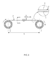
- FIG. 3 is a schematic front view of a cathode cutting device using a laser according to the present invention
- FIG. 4 is a cross-sectional view taken along line IV-IV' in FIG. 3 .
- the cathode cutting device further includes a un-winder 5 unwinding the cathode sheet 3 and a winder 7 disposed at an interval from the un-winder 5 and re-winding the cathode sheet 3 being unwound by the un-winder 5, in addition to the laser oscillator 11 and the focusing lens 15 as described above.
- the focusing lens 15 plays a role in radiating a laser beam to a suspension section S of the cathode sheet 3 between the un-winder 5 and the winder 7.
- the cathode sheet 3 is wound on the un-winder 5, which unwinds the cathode sheet 3, rotating clockwise in FIG. 3 .
- the winder 7 re-winds the cathode sheet 3 unwound by the un-winder 5, rotating clockwise in FIG. 3 .
- a unwound section between the un-winder 5 and the winder 7 is referred to as the suspension section S, and the cathode sheet 3 may be unwound and wound under a certain tension to prevent the cathode sheet 3 corresponding to the suspension section S from becoming rippled or folded while the cathode sheet is unwound or wound.
- a first mirror 13 and a second mirror 14 may be disposed on an optical path connecting to the laser oscillator 11 and the focusing lens 15.
- the first mirror 13 and the second mirror 14 play a role in moving the focal spot of the laser beam focused by the focusing lens 15 to a desired location on the surface of the cathode sheet 3.
- the first mirror 13 may be rotatable about a first axis and the second mirror 14 be rotatable about a second axis, in which case the first axis and the second axis makes an orthogonal coordinate system and it is possible to move the focal spot of a laser beam to focus to numerous points on the surface of the cathode sheet 3 by adjusting a rotation angle of the first mirror 13 relative to the first axis and a rotation angle of the second mirror 14 relative to the second axis.
- a light width adjuster 12 may be disposed on the optical path, in which case the light width adjuster 12 is located closer the first mirror 13 to the laser oscillator 11 and the second mirror 14 and plays a role in adjusting the light width of the laser beam emitted from the laser oscillator 11.
- the light width adjuster 12 may include a first lens 12A and a second lens 12B that is located farther than the first lens 12A from the laser oscillator 11, and have a structure (not shown) adjusting the distance between the first lens 12A and the second lens 12B.
- FIG. 5 is a diagram representing the location change of the focal spot of a focused laser beam according to a change in width of light.
- the laser beam passing through the light width adjuster 12 may enter parallel to the focusing lens 15 (represented by a solid line), in a divergence state (represented by a dashed and dotted line) or in a convergence state (represented by a dotted line), and each laser beam is focused on the locations Z2, Z2, and Z3 in turn. Only three examples are described but it is possible to very finely adjust the distance between the focal spot of the focused laser beam and the cathode sheet 3 by finely adjusting a degree of divergence or convergence of the laser beam.
- the present invention uses a method of adjusting the gap between the first lens 12A and the second lens 12B.
- the present invention uses a method of adjusting the height of the focal spot by adjusting the mutual distance between optical lenses, and this method has an advantage in that it is less affected by the external shock than the actuator device and is not affected by a micro error due to a gap generated when the actuator device is adjusted.
- the cathode cutting device may further include a sheet guide to minimize a possibility that the cathode sheet 3 may be incompletely cut.
- the sheet guide 20 is described in detail with reference to FIGS. 1 , 3 and 4 .
- the sheet guide 20 is a component for supporting at least a portion of the suspension section S in order to inhibit, a region of the suspension section S of the cathode sheet 3 to which a focused laser is radiated, from sagging.
- the sheet guide 20 includes a first guide 21 supporting a first surface 1 being a sagging surface of both surfaces of the cathode sheet 3 corresponding to the suspension section S, and may further include a second guide 22 which is disposed over a second surface 2 at an interval from the second surface 2 of the suspension section S in order to inhibit the suspension section S of the cathode sheet 3 from rolling in the opposite direction to the first surface 1.
- the sheet guide 20 including the first guide 21 and the second guide 22 may be formed in the shape of the letter U as shown in FIGS. 1 and 4 and although FIGS. 1 and 4 show that the sheet guide guides approximately half the width of the cathode sheet 3, it is also possible to install the sheet guide to guide the full width of the cathode sheet 3.
- the laser oscillator 11, the first mirror 13, the second mirror 14, and the focusing lens 15 that have been described above are used.
- the thickness of the cathode sheet 3 is about 140 ⁇ m
- a 20 W laser oscillator 11 is used to generate a laser
- a generated laser is a single mode fiber laser having M 2 of about 1.3
- a wavelength is about 1070 nm.
- the diameter of a laser beam entering the focusing lens 15 is about 10 mm.
- ⁇ Table 1> represents a result of cutting a cathode while changing each experiment condition, when the focal length of the focusing lens 15 is about 254 mm and the spot size of the laser beam is about 45 ⁇ m.
- ⁇ Table 1> Frequency (kHz) Cutting Speed of Cathode (mm/s) Active Material Uncoated Portion (Cut O, Uncut X) Active Material Coated Portion (Cut O, Uncut X) Energy Density of Focal Spot (J/cm 2 ) 35 100 ⁇ ⁇ 35.9 110 ⁇ ⁇ 120 ⁇ ⁇ 130 ⁇ ⁇ 140 ⁇ ⁇ 150 ⁇ ⁇ 50 100 ⁇ ⁇ 25.2 110 ⁇ ⁇ 120 ⁇ ⁇ 130 ⁇ ⁇ 140 ⁇ ⁇ 150 ⁇ ⁇ 75 100 ⁇ ⁇ 16.8 110 ⁇ ⁇ 130 ⁇ ⁇ 130 ⁇ ⁇ 140 ⁇ ⁇ 150 ⁇ ⁇ ⁇
- the frequency of the laser beam increases to about 75 kHz
- the energy density of the focal spot becomes about 16.8 J/cm 2 , in which case it was very difficult to cut the active material uncoated portion even if the coating speed of the cathode is relatively slow, e.g., 100 mm/s.
- the active material uncoated portion was not cut however the frequency increases while the energy density of the focal spot is maintained at about 16.8 J/cm 2 .
- the energy density of the focal spot gradually increases to become about 25J/cm 2 while the frequency is maintained at about 75 kHz, the active material uncoated portion was cut.
- the cathode sheet 3 for manufacturing a cathode plate configuring an electrode assembly used typically for a secondary battery when the energy density of the focal spot of the laser beam radiated to the surface of the cathode sheet 3 becomes about 25 J/cm 2 , and in comparison, the frequency of the laser beam has no effect on the cutting of the cathode sheet 3.
- ⁇ Table 2> represents a result of cutting a cathode while changing each experiment condition, when the focal length of the focusing lens 15 is about 163 mm and the spot size of the laser beam is about 29 ⁇ m.
- ⁇ Table 2> Frequency (kHz) Cutting Speed of Cathode (mm/s) Active Material Uncoated Portion (Cut O, Uncut X) Active Material Coated Portion (Cut O, Uncut X) Energy Density of Focal Spot (J/cm 3 ) 35 100 ⁇ ⁇ 86.5 140 ⁇ ⁇ 180 ⁇ ⁇ 220 ⁇ 260 ⁇ ⁇ 50 100 ⁇ ⁇ 60.6 140 ⁇ ⁇ 180 ⁇ ⁇ 220 ⁇ ⁇ 260 ⁇ ⁇ 75 100 ⁇ ⁇ 40.4 140 ⁇ ⁇ 180 ⁇ ⁇ 220 ⁇ ⁇ 260 ⁇ ⁇ ⁇ ⁇
- the active material uncoated portion was not cut but it is possible to achieve a yield of the cathode plate enough to come to the market even if the cutting speed of the cathode does not approach about 260 mm/s.
- the frequency in both Experiments 1 and 2 changed to 35 kHz, 50 kHz, and 75 kHz, in which case it was found that the frequency of the laser beam has an adverse affect on the cutting of the cathode sheet 3 when the energy density of the focal spot is higher than about 25.2J/cm 2 .
- the spot sizes of the laser beams in Experiments 1 and 2 above are 45 ⁇ m and 29 ⁇ m respectively, in which case when the size of the focal spot varies under frequency, cutting speed and energy density at which both the active material coated portion and the active material uncoated portion are easily cut, the cutting speed of the cathode remarkably decreased or the cutting was incompletely performed when the size of the focal spot of the laser beam radiated to the surface of the cathode sheet 3 is smaller than or equal to about 10 ⁇ m or equal to or larger than 50 ⁇ m.
- Experiments 1 and 2 and an additional experiment drew a conclusion that it is possible to cut the cathode sheet 3 to provide a yield suitable for coming to the market when the size of the focal spot of the laser beam radiated to the surface of the cathode sheet 3 is about 10 ⁇ m to about 50 ⁇ m and the energy density of the focal spot is equal to or higher than about 25 J/cm 2 .
- Foil forming the cathode sheet 3 and an active material coated on the foil may be maintained in independent layers even after the cathode sheet 3 is cut, the reason for which is because the quality of the cathode goes down when the laser beam melts the foil and the active material with excessively strong energy so that the foil and the active material are mixed and thus the interface between the foil and the active material becomes unclear.
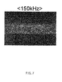
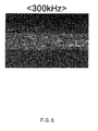
- FIGS. 3 to 9 are pictures representing the cross-sectional state of the cathode sheet according to a change in frequency of the laser beam
- the frequency of the laser beam is about 70 kHz
- the interface between a central foil and the active material coated on both sides of the foil is very clear, and even when the frequency is about 150 kHz or about 300 kHz, it is less easy to identify the interface between the foil and the active material in comparison to 70 kHz.
- the frequency is about 35 kHz, about 50 kHz, and about 75 kHz (which have been used in Experiments 1 and 2)
- the interface between the foil and the active material was very clear like when the frequency is about 70 kHz.
- the focal length of the focusing lens 15 is, for example, about 254 mm and about 163 mm, and when the focal length of the focusing lens 15 is within a range of about 100 mm to about 300 mm including the figures, it was possible to adjust the size of the focal spot of the laser beam to be within about 10 ⁇ m to about 50 ⁇ m.
- the power of the laser oscillator 11 was 20 W in the experiments, in which case it was possible to find that the cutting quality of the cathode sheet 3 goes down so that it may be difficult to identify the interface between the foil and the active material forming the cathode sheet 3 when the power is over about 500 W.
- the power of the laser oscillator 11 may be about 20 W to about 500 W.
- the cutting quality of the cathode sheet 3 may go down when the cathode sheet 3 vertically rolls in FIG. 1 while it is unwound and wound by the un-winder 5 and the winder 7.
- the first guide 21 and the second guide 22 are needed and it was possible to find that the cathode is stably cut when the gap between the first guide 21 and the second guide 22 is about 0.5 mm to about 2 mm.
- the cathode cutting device by determining process conditions optimized for cutting the cathode sheet 3, it is possible to produce the cathode appropriately maintaining the balance between quality and yield, and since the cathode sheet 3 is cut by using the laser in stead of a mold cutter, there is an advantage in that it is possible to increase an operation rate because there is no need to stop a manufacturing line even if various cathodes are manufactured on a manufacturing line. Accordingly, it is possible to lower the cost of a cathode coating process.
Landscapes
- Physics & Mathematics (AREA)
- Optics & Photonics (AREA)
- Engineering & Computer Science (AREA)
- Plasma & Fusion (AREA)
- Mechanical Engineering (AREA)
- Electromagnetism (AREA)
- Laser Beam Processing (AREA)
- Battery Electrode And Active Subsutance (AREA)
Abstract
Description
- The present invention relates to a cathode cutting device using a laser and more particularly, to a cathode cutting device that may continuously cut a cathode sheet by using a laser.
- In general, a demand for a secondary battery is increasing due to the technological development of a mobile device and an increase in demand therefor, and among others, a lithium (ion/polymer) secondary battery having a high energy density and operating voltage and excellent preservation and life characteristics is being widely used as an energy source for various electronic products including various mobile devices.
- The lithium (ion/polymer) secondary battery has a structure in which an electrode assembly having a structure in which a cathode and an anode are alternately stacked and a separator is disposed inbetween is stored in an external casing.
- An electrode forming the electrode assembly has a structure in which an electrode tab is exposed to one end of a flat electrode plate, and a mold cutter has been typically used in order to manufacture the electrode plate to which the electrode tab is exposed. In particular, the electrode plate to which the electrode tab is exposed is manufactured by using the mold cutter having a shape capable of remaining the shape of the electrode tab on an electrode plate material and cutting out other portions.
- As such, when an electrode material is cut by using the mold cutter, there is an advantage in that cutting quality is high but there are limitations in that it takes a lot of time to manufacture a mold cutter having a precise shape and the mold cutter itself is expensive, and there is another limitation in that it has no choice but to cut the electrode material according to the shape of the mold cutter only. Thus, in order to manufacture an electrode plate having various shapes and sizes on a factory line cutting the electrode material, processes of stopping a production line, replacing the mold cutter and then re-operating the production line should be repeated many times.
- Providing and replacing various kinds of mold cutters do not only increase the production cost of the mold cutter but also remarkably decrease the yield of the electrode plate that may be produced for a unit time.
- In order to solve the foregoing limitations, the present invention addresses a cathode among electrodes and provides a cathode cutting device having high yield and operation rate because there is no need to stop a manufacturing line even if cathodes having various shapes are manufactured on a manufacturing line.
- The present invention also provides a cathode cutting device that may lower the cost of a cathode cutting process.
- According to an aspect of the present invention, there is provided a According to an aspect of the present invention, there is provided a cathode cutting device using a laser including: a laser oscillator emitting a laser beam; and a focusing lens focusing the laser beam emitted from the laser oscillator and radiating a focused laser beam to a cathode sheet to cut the cathode sheet, wherein the a size of a focal spot of the laser beam radiated to a surface of the cathode sheet is about 10 µm to about 50 µm, and energy density of the focal spot is equal to or higher than about 25 J/cm2.
- A frequency of the laser beam may be about 35 kHz to about 300 kHz.
- Power of the laser beam may be about 20 W to about 500 W.
- The laser may have a beam mode parameter M2 of 1 to 2.0, the beam mode parameter being a variable representing quality of the laser.
- A focal length of the focusing lens may be about 100 mm to about 300 mm.
- The cathode cutting device may further include: an un-winder unwinding the cathode sheet; and a winder disposed at an interval from the un-winder and re-winding the cathode sheet being unwound from the un-winder, wherein the focusing lens may radiate the laser beam to a suspension section of the cathode sheet between the un-winder and the winder.
- The cathode cutting device may further include a sheet guide supporting at least a portion of the suspension section to inhibit, a region of the suspension section of the cathode sheet to which a focused laser is radiated, from sagging.
- The sheet guide may include a first guide supporting a first surface being a sagging surface of both surfaces of the suspension section of the cathode sheet, and a second guide disposed over a second surface at an interval from the second surface of the suspension section to inhibit the suspension section of the cathode sheet from rolling in the opposite direction to the sagging surface of both surfaces of the suspension section of the cathode sheet.
- A gap between the first guide and the second guide may be about 0.5 mm to about 2 mm.
- The cathode cutting device may further include first and second mirrors disposed on an optical path connecting to the laser oscillator and the focusing lens, wherein the first and second mirrors may be rotatable about first and second axes forming an orthogonal coordinate system to allow a focal spot of a laser beam focused by the focusing lens to move to a desired location on a surface of the cathode sheet.
- The cathode cutting device may further include a light width adjuster disposed on the optical path, wherein the light width adjuster may be located closer than the first and second mirrors to the laser oscillator to adjust a light width of the laser beam emitted from the laser oscillator.
- The light width adjuster may include a first lens and a second lens located farther than the first lens from the laser oscillator, and the light width adjuster may have a distance adjustment structure between the first lens and the second lens to adjust a mutual distance between a focal spot of a laser beam focused through the focusing lens and the cathode sheet.
- The laser may be a diode pumped solid state laser (DPSS) allowing pulse modulation.
- The laser may be a fiber laser.
- According to the present invention, it is possible to provide a cathode cutting device having a high yield and operation rate because there is no need to stop a manufacturing line even if cathodes having various shapes are manufactured on a manufacturing line.
- Also, it is possible to provide a cathode cutting device that may lower the cost of a cathode cutting process.
- Since the attached drawings illustrate exemplary embodiments of the present invention and play a role in conveying the technical scope of the present invention along with the detailed description, the present invention should not be construed as being limited to matters depicted in the drawings.
-
FIG. 1 is a perspective view of a portion of a cathode cutting device using a laser according to the present invention. -
FIG. 2 is a diagram representing an optical path of a laser beam passing through a focusing lens. -
FIG. 3 is a schematic front view of a cathode cutting device using a laser according to the present invention. -
FIG. 4 is a cross-sectional view taken along line IV-IV' inFIG. 3 . -
FIG. 5 is a diagram representing the location change of a focal spot of a focused laser beam according to a change in light width. -
FIGS. 6 to 9 are pictures representing the sectional state of a cathode sheet according to a frequency change of a laser beam. - In the following, an exemplary embodiment of the present invention is described in detail. However, the present invention is not limited or defined by the following embodiment.
- The terms or words used in the detailed description and claims should not be limitatively construed as typical meanings or meanings indicated in dictionaries but should be construed as meanings and concepts matching the technical spirit of the present invention based on the principle that the inventor may properly define the concepts of terms in order to describe his or her invention in the best mode.
- In the drawing, the size of each component or a specific part of the component is exaggerated, omitted or simply shown for the convenience and clarity of description. Thus, the size of each component does not substantially reflect an actual size. When it is determined that a detailed description of a related known function or configuration may unnecessarily obscure the subject of the present invention, such a description is not provided.
-
FIG. 1 is a perspective view of a portion of a cathode cutting device using a laser according to the present invention. - Referring to
FIG. 1 , a cathode cutting device using a laser according to an exemplary embodiment of the present invention (hereinafter, referred to as a "cathode cutting device") includes alaser oscillator 11 emitting a laser beam, and a focusinglens 15 focusing the laser beam emitted from thelaser oscillator 11 and radiating a focused beam to acathode sheet 3 in order to cut thecathode sheet 3. A focal spot of a laser beam passing through the focusinglens 15 may be in contact with the surface of thecathode sheet 3. In this example, the focal spot indicates a laser beam in depth of focus to be described below. - A laser used in the present invention may be a laser of a pulse modulation system having a pulse width smaller than or equal to 1µs in oscillation shape of a laser and a Q-switching or master oscillator pulse amplification (MOPA) system may be used as the pulse modulation system. However, the present invention is not limited thereto and any pulse modulation system having a pulse width of 10 ps to 1 1µs may be used.
- An optical fiber may be employed as a resonator used for generating a laser from the
laser oscillator 11, a laser emitted by using the optical fiber as the resonator is referred to as a fiber laser, and the present invention may use the fiber laser. Also, a diode pumped solid state laser (DPSS) may be used. -
FIG. 2 is a diagram representing an optical path of a laser beam passing through a focusing lens. - When light width is BW, the minimum radius of a focused laser spot is W0, and the focal distance of the focusing
lens 15 is f, the distance between two points at which the radius of the focused laser spot is
- The size W0 of the focal spot may be represented by Equation ① below:

- In Equation ①, λ is the wavelength of a laser, M2 is a variable that is a beam mode parameter, represents the quality of the laser and has a theorectial value of 1 and an actual value of about 1.3. M2 of the laser used in the present invention may be close to 1 but depend on the power and oscillation system of the laser. However, when seeing Equation ①, M2 may have a value of 1 to 2.0 because the depth of focus increases in order to decrease the size of the focal spot when M2 is equal to or larger than 2. The parameter f is the focal distance of the focusing
lens 15 and D is the light width of a laser beam entering the focusinglens 15. - The depth of focus may be represented by
Equation ②, where L represents the depth of focus which is referred to also as a Rayleigh length:
- From the relationship between
Equations ① and ② above,Equation ③ below is derived: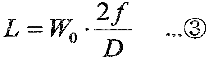
- When the size W0 of the focal spot is small, the energy of the laser beam is concentrated on a narrow region and thus it is easy to cut a cutting target, and when the depth of focus is long, it is possible to easily cut even if the location of the cutting target relative to the laser beam varies or the surface of the cutting target is not even. Ideally, the size W0 of the focal spot may be small and the depth of focus may be long.
- However, when seeing
Equation ③ above, the depth of focus is proportional to the size of the laser spot. - Thus, when the size of the focal spot is small, the energy density per unit area of the laser beam may be high but the depth of focus also shortens and thus the cutting target is not easily cut when the location of the cutting target relative to the laser beam varies or the surface of the cutting target is not even.
- On the contrary, when the depth of focus is long, cutting is less sensitive to what the location of the cutting target relative to the laser beam varies or the surface of the cutting target is not even. Thus, since setting the location of the cutting target or a focus is easy but the size of the focal spot also increases along with the depth of focus, there is a limitation in that the energy density per unit area of the laser beam decreases to a level lower than a level at which it is possible to cut the cutting target.
- As such, since it is difficult to make the depth of focus very long and the size of the focal spot very small, maintaining the balance between the depth of focus and the size of the focal spot is very important in cutting the
cathode sheet 3. Also, in cutting a cathode by using the laser, it is necessary to check which variable is important. - In the following, a cathode cutting device used for a related experiment and capable of being used actually in a cathode cutting process is first described and next, maintaining the balance between the depth of focus and the size of the laser spot and an experiment for checking which variable is important and its result are described.
-
FIG. 3 is a schematic front view of a cathode cutting device using a laser according to the present invention, andFIG. 4 is a cross-sectional view taken along line IV-IV' inFIG. 3 . - Referring to
FIGS. 1 ,3 and4 , the cathode cutting device according to the present invention further includes aun-winder 5 unwinding thecathode sheet 3 and a winder 7 disposed at an interval from theun-winder 5 and re-winding thecathode sheet 3 being unwound by theun-winder 5, in addition to thelaser oscillator 11 and the focusinglens 15 as described above. - The focusing
lens 15 plays a role in radiating a laser beam to a suspension section S of thecathode sheet 3 between the un-winder 5 and the winder 7. - The
cathode sheet 3 is wound on theun-winder 5, which unwinds thecathode sheet 3, rotating clockwise inFIG. 3 . In addition, the winder 7 re-winds thecathode sheet 3 unwound by theun-winder 5, rotating clockwise inFIG. 3 . - A unwound section between the un-winder 5 and the winder 7 is referred to as the suspension section S, and the
cathode sheet 3 may be unwound and wound under a certain tension to prevent thecathode sheet 3 corresponding to the suspension section S from becoming rippled or folded while the cathode sheet is unwound or wound. - A
first mirror 13 and asecond mirror 14 may be disposed on an optical path connecting to thelaser oscillator 11 and the focusinglens 15. - The
first mirror 13 and thesecond mirror 14 play a role in moving the focal spot of the laser beam focused by the focusinglens 15 to a desired location on the surface of thecathode sheet 3. Thefirst mirror 13 may be rotatable about a first axis and thesecond mirror 14 be rotatable about a second axis, in which case the first axis and the second axis makes an orthogonal coordinate system and it is possible to move the focal spot of a laser beam to focus to numerous points on the surface of thecathode sheet 3 by adjusting a rotation angle of thefirst mirror 13 relative to the first axis and a rotation angle of thesecond mirror 14 relative to the second axis. - Also, a
light width adjuster 12 may be disposed on the optical path, in which case thelight width adjuster 12 is located closer thefirst mirror 13 to thelaser oscillator 11 and thesecond mirror 14 and plays a role in adjusting the light width of the laser beam emitted from thelaser oscillator 11. - The
light width adjuster 12 may include afirst lens 12A and asecond lens 12B that is located farther than thefirst lens 12A from thelaser oscillator 11, and have a structure (not shown) adjusting the distance between thefirst lens 12A and thesecond lens 12B. - It is possible to adjust the distance between the
first lens 12A and thesecond lens 12B by moving at least one of thefirst lens 12A and thesecond lens 12B, and accordingly, it is possible to adjust the width of light entering thefirst mirror 13 and the distance between the focal spot of the laser beam focused through the focusinglens 15 and thecathode sheet 3. A related description is provided in more detail with reference toFIG. 5 . -
FIG. 5 is a diagram representing the location change of the focal spot of a focused laser beam according to a change in width of light. The laser beam passing through thelight width adjuster 12 may enter parallel to the focusing lens 15 (represented by a solid line), in a divergence state (represented by a dashed and dotted line) or in a convergence state (represented by a dotted line), and each laser beam is focused on the locations Z2, Z2, and Z3 in turn. Only three examples are described but it is possible to very finely adjust the distance between the focal spot of the focused laser beam and thecathode sheet 3 by finely adjusting a degree of divergence or convergence of the laser beam. - Since the focal spot needs to be located on the surface of the
cathode sheet 3 in order to cut the cathode sheet as desired, accurately matching the focal spot with the surface of thecathode spot 3 is necessarily needed, and to this end, the present invention uses a method of adjusting the gap between thefirst lens 12A and thesecond lens 12B. - In order to adjust the height of the focal spot of the laser beam, an actuator having adjustable height is typically used, and if an actuator device is used, it is easy for an installation location to finely vary or go wrong by an external shock. Thus, the present invention uses a method of adjusting the height of the focal spot by adjusting the mutual distance between optical lenses, and this method has an advantage in that it is less affected by the external shock than the actuator device and is not affected by a micro error due to a gap generated when the actuator device is adjusted.
- On the other hand, even if the focal spot is finely adjusted through the
light width adjuster 12, there is a possibility that thecathode sheet 3 is not easily cut when the height of thecathode sheet 3 corresponding to the suspension section S is not constantly maintained. - The cathode cutting device according to the present invention may further include a sheet guide to minimize a possibility that the
cathode sheet 3 may be incompletely cut. - The
sheet guide 20 is described in detail with reference toFIGS. 1 ,3 and4 . - The
sheet guide 20 is a component for supporting at least a portion of the suspension section S in order to inhibit, a region of the suspension section S of thecathode sheet 3 to which a focused laser is radiated, from sagging. Thesheet guide 20 includes afirst guide 21 supporting a first surface 1 being a sagging surface of both surfaces of thecathode sheet 3 corresponding to the suspension section S, and may further include asecond guide 22 which is disposed over asecond surface 2 at an interval from thesecond surface 2 of the suspension section S in order to inhibit the suspension section S of thecathode sheet 3 from rolling in the opposite direction to the first surface 1. - The
sheet guide 20 including thefirst guide 21 and thesecond guide 22 may be formed in the shape of the letter U as shown inFIGS. 1 and4 and althoughFIGS. 1 and4 show that the sheet guide guides approximately half the width of thecathode sheet 3, it is also possible to install the sheet guide to guide the full width of thecathode sheet 3. - As described above, since it is difficult to make the depth of focus very long and the size of the focal spot of the laser beam very small, maintaining the balance between the depth of focus and the size of the focal spot in cutting the
cathode sheet 3 is very important and there is a need to know which variable is important. An experiment for finding it is described below. - In the experiment, the
laser oscillator 11, thefirst mirror 13, thesecond mirror 14, and the focusinglens 15 that have been described above are used. The thickness of thecathode sheet 3 is about 140 µm, a 20W laser oscillator 11 is used to generate a laser, a generated laser is a single mode fiber laser having M2 of about 1.3, and a wavelength is about 1070 nm. Also, the diameter of a laser beam entering the focusinglens 15 is about 10 mm. - Firstly, <Table 1> represents a result of cutting a cathode while changing each experiment condition, when the focal length of the focusing
lens 15 is about 254 mm and the spot size of the laser beam is about 45 µm.<Table 1> Frequency (kHz) Cutting Speed of Cathode (mm/s) Active Material Uncoated Portion (Cut O, Uncut X) Active Material Coated Portion (Cut O, Uncut X) Energy Density of Focal Spot (J/cm2) 35 100 ○ ○ 35.9 110 ○ ○ 120 ○ ○ 130 ○ × 140 ○ × 150 ○ × 50 100 ○ ○ 25.2 110 ○ ○ 120 ○ ○ 130 ○ ○ 140 ○ × 150 ○ × 75 100 × ○ 16.8 110 × ○ 130 × ○ 130 × ○ 140 × ○ 150 × ○ - Referring to <Table 1> above, when the frequency of the laser beam is about 35 kHz and the energy density of the focal spot is about 35.9 J/cm2 and when the frequency of the laser beam is about 50 kHz and the energy density of the focal spot is about 25.2 J/cm2, it was possible to cut a cathode active material uncoated portion, and when the cutting speed of a cathode is not only about 100 mm/s but also about 150 mm/s, it was possible to cut an active material uncoated portion.
- However, when the frequency of the laser beam increases to about 75 kHz, the energy density of the focal spot becomes about 16.8 J/cm2, in which case it was very difficult to cut the active material uncoated portion even if the coating speed of the cathode is relatively slow, e.g., 100 mm/s. It was assumed as a frequency problem or the energy density problem of the focal spot, in which case the active material uncoated portion was not cut however the frequency increases while the energy density of the focal spot is maintained at about 16.8 J/cm2. On the contrary, when the energy density of the focal spot gradually increases to become about 25J/cm2 while the frequency is maintained at about 75 kHz, the active material uncoated portion was cut.
- As a result, it was found that there is no problem in cutting, as desired, the
cathode sheet 3 for manufacturing a cathode plate configuring an electrode assembly used typically for a secondary battery when the energy density of the focal spot of the laser beam radiated to the surface of thecathode sheet 3 becomes about 25 J/cm2, and in comparison, the frequency of the laser beam has no effect on the cutting of thecathode sheet 3. - Next, <Table 2> below represents a result of cutting a cathode while changing each experiment condition, when the focal length of the focusing
lens 15 is about 163 mm and the spot size of the laser beam is about 29 µm.<Table 2> Frequency (kHz) Cutting Speed of Cathode (mm/s) Active Material Uncoated Portion (Cut O, Uncut X) Active Material Coated Portion (Cut O, Uncut X) Energy Density of Focal Spot (J/cm3) 35 100 ○ ○ 86.5 140 ○ ○ 180 ○ ○ 220 ○ ○ 260 ○ × 50 100 ○ ○ 60.6 140 ○ ○ 180 ○ ○ 220 ○ ○ 260 ○ × 75 100 ○ ○ 40.4 140 ○ ○ 180 ○ ○ 220 ○ ○ 260 ○ × - Referring to <Table 2> above, when the frequency of the laser beam is about 35 kHz, about 50 kHz, and about 75 kHz and when the energy density of the focal spot is about 86.5 J/cm2, 60.6 J/cm2, and 40.4 J/cm2, it was possible to cut both the active material coated portion and active material uncoated portion of the
cathode sheet 3 when the cutting speed of the cathode is not only about 100 mm/s but also about 220 mm/s. However, when the cutting speed of the cathode is about 260 mm/s, the active material uncoated portion was not cut but it is possible to achieve a yield of the cathode plate enough to come to the market even if the cutting speed of the cathode does not approach about 260 mm/s. - It is possible to conclude that the energy density of the focal spot in
Experiment 2 is higher than about 25.2 J/cm2 and the cutting of thecathode sheet 3 is easily implemented in such an energy density state, when compared to Experiment 1. - Also, the frequency in both
Experiments 1 and 2 changed to 35 kHz, 50 kHz, and 75 kHz, in which case it was found that the frequency of the laser beam has an adverse affect on the cutting of thecathode sheet 3 when the energy density of the focal spot is higher than about 25.2J/cm2. - The spot sizes of the laser beams in
Experiments 1 and 2 above are 45 µm and 29 µm respectively, in which case when the size of the focal spot varies under frequency, cutting speed and energy density at which both the active material coated portion and the active material uncoated portion are easily cut, the cutting speed of the cathode remarkably decreased or the cutting was incompletely performed when the size of the focal spot of the laser beam radiated to the surface of thecathode sheet 3 is smaller than or equal to about 10µm or equal to or larger than 50 µm. - As a result,
Experiments 1 and 2 and an additional experiment drew a conclusion that it is possible to cut thecathode sheet 3 to provide a yield suitable for coming to the market when the size of the focal spot of the laser beam radiated to the surface of thecathode sheet 3 is about 10 µm to about 50 µm and the energy density of the focal spot is equal to or higher than about 25 J/cm2. - Foil forming the
cathode sheet 3 and an active material coated on the foil may be maintained in independent layers even after thecathode sheet 3 is cut, the reason for which is because the quality of the cathode goes down when the laser beam melts the foil and the active material with excessively strong energy so that the foil and the active material are mixed and thus the interface between the foil and the active material becomes unclear. -
FIGS. 3 to 9 are pictures representing the cross-sectional state of the cathode sheet according to a change in frequency of the laser beam, and inFIGS. 6 to 9 , when the frequency of the laser beam is about 70 kHz, the interface between a central foil and the active material coated on both sides of the foil is very clear, and even when the frequency is about 150 kHz or about 300 kHz, it is less easy to identify the interface between the foil and the active material in comparison to 70 kHz. Also, when the frequency is about 35 kHz, about 50 kHz, and about 75 kHz (which have been used in Experiments 1 and 2), the interface between the foil and the active material was very clear like when the frequency is about 70 kHz. - However, when the frequency is about 50 kHz, it was very difficult to identify the interface between the foil and the active material, and as a result, only when the frequency is adjusted to be within a range of about 35 kHz to about 300 kHz, it was possible to manufacture a cathode plate suitable for coming to the market.
- In
Experiments 1 and 2, the focal length of the focusinglens 15 is, for example, about 254 mm and about 163 mm, and when the focal length of the focusinglens 15 is within a range of about 100 mm to about 300 mm including the figures, it was possible to adjust the size of the focal spot of the laser beam to be within about 10 µm to about 50 µm. Also, the power of thelaser oscillator 11 was 20 W in the experiments, in which case it was possible to find that the cutting quality of thecathode sheet 3 goes down so that it may be difficult to identify the interface between the foil and the active material forming thecathode sheet 3 when the power is over about 500 W. - Thus, the power of the
laser oscillator 11 may be about 20 W to about 500 W. - On the other hand, even if the above conditions are all satisfied, the cutting quality of the
cathode sheet 3 may go down when thecathode sheet 3 vertically rolls inFIG. 1 while it is unwound and wound by theun-winder 5 and the winder 7. - In order to prevent such a situation, the
first guide 21 and thesecond guide 22 are needed and it was possible to find that the cathode is stably cut when the gap between thefirst guide 21 and thesecond guide 22 is about 0.5 mm to about 2 mm. - According to the cathode cutting device according to the present invention as described so far, by determining process conditions optimized for cutting the
cathode sheet 3, it is possible to produce the cathode appropriately maintaining the balance between quality and yield, and since thecathode sheet 3 is cut by using the laser in stead of a mold cutter, there is an advantage in that it is possible to increase an operation rate because there is no need to stop a manufacturing line even if various cathodes are manufactured on a manufacturing line. Accordingly, it is possible to lower the cost of a cathode coating process. - The detailed description of the present invention as described above has provided particular embodiments. However, many variations may be implemented without departing from the scope of the present invention. The technical spirit of the present invention should not be defined to be limited to the embodiments of the present invention and should be defined by the following claims and equivalent thereto.
Claims (14)
- A cathode cutting device using a laser comprising:a laser oscillator emitting a laser beam; anda focusing lens focusing the laser beam emitted from the laser oscillator and radiating a focused laser beam to a cathode sheet to cut the cathode sheet,wherein the a size of a focal spot of the laser beam radiated to a surface of the cathode sheet is about 10 µm to about 50 µm, and energy density of the focal spot is equal to or higher than about 25 J/cm2.
- The cathode cutting device of claim 1, wherein a frequency of the laser beam is about 35 kHz to about 300 kHz.
- The cathode cutting device of claim 1, wherein power of the laser beam is about 20 W to about 500 W.
- The cathode cutting device of claim 1, wherein the laser has a beam mode parameter M2 of 1 to 2.0, the beam mode parameter being a variable representing quality of the laser.
- The cathode cutting device of claim 1, wherein a focal length of the focusing lens is about 100 mm to about 300 mm.
- The cathode cutting device of claim 1, further comprising:an un-winder unwinding the cathode sheet; anda winder disposed at an interval from the un-winder and re-winding the cathode sheet being unwound from the un-winder,wherein the focusing lens radiates the laser beam to a suspension section of the cathode sheet between the un-winder and the winder.
- The cathode cutting device of claim 6, further comprising a sheet guide supporting at least a portion of the suspension section to inhibit, a region of the suspension section of the cathode sheet to which a focused laser is radiated, from sagging.
- The cathode cutting device of claim 7, wherein the sheet guide comprises a first guide supporting a first surface being a sagging surface of both surfaces of the suspension section of the cathode sheet, and a second guide disposed over a second surface at an interval from the second surface of the suspension section to inhibit the suspension section of the cathode sheet from rolling in the opposite direction to the sagging surface of both surfaces of the suspension section of the cathode sheet.
- The cathode cutting device of claim 8, wherein a gap between the first guide and the second guide is about 0.5 mm to about 2 mm.
- The cathode cutting device of claim 6, further comprising first and second mirrors disposed on an optical path connecting to the laser oscillator and the focusing lens, wherein the first and second mirrors are rotatable about first and second axes forming an orthogonal coordinate system to allow a focal spot of a laser beam focused by the focusing lens to move to a desired location on a surface of the cathode sheet.
- The cathode cutting device of claim 10, further comprising a light width adjuster disposed on the optical path, wherein the light width adjuster is located closer than the first and second mirrors to the laser oscillator to adjust a light width of the laser beam emitted from the laser oscillator.
- The cathode cutting device of claim 11, wherein the light width adjuster comprises a first lens and a second lens located farther than the first lens from the laser oscillator, and
the light width adjuster has a distance adjustment structure between the first lens and the second lens to adjust a mutual distance between a focal spot of a laser beam focused through the focusing lens and the cathode sheet. - The cathode cutting device of claim 1, wherein the laser is a diode pumped solid state laser (DPSS) allowing pulse modulation.
- The cathode cutting device of claim 1, wherein the laser is a fiber laser.
Applications Claiming Priority (2)
| Application Number | Priority Date | Filing Date | Title |
|---|---|---|---|
| KR1020130132063A KR101680416B1 (en) | 2013-11-01 | 2013-11-01 | Apparatus of cutting positive electrode using laser |
| PCT/KR2014/010370 WO2015065105A1 (en) | 2013-11-01 | 2014-10-31 | Positive electrode cutting device using laser |
Publications (3)
| Publication Number | Publication Date |
|---|---|
| EP2889103A1 true EP2889103A1 (en) | 2015-07-01 |
| EP2889103A4 EP2889103A4 (en) | 2015-12-16 |
| EP2889103B1 EP2889103B1 (en) | 2017-06-21 |
Family
ID=53004610
Family Applications (1)
| Application Number | Title | Priority Date | Filing Date |
|---|---|---|---|
| EP14843174.5A Active EP2889103B1 (en) | 2013-11-01 | 2014-10-31 | Positive electrode cutting device using laser |
Country Status (6)
| Country | Link |
|---|---|
| US (1) | US10005157B2 (en) |
| EP (1) | EP2889103B1 (en) |
| JP (1) | JP6059819B2 (en) |
| KR (1) | KR101680416B1 (en) |
| CN (1) | CN104755219A (en) |
| WO (1) | WO2015065105A1 (en) |
Cited By (3)
| Publication number | Priority date | Publication date | Assignee | Title |
|---|---|---|---|---|
| RU2683146C1 (en) * | 2018-05-15 | 2019-03-26 | Общество с ограниченной ответственностью "ПКТ" | Method for cutting beryllium foil |
| JP2023053696A (en) * | 2021-10-01 | 2023-04-13 | 古河電気工業株式会社 | Metal foil laser cutting method |
| EP4672347A1 (en) * | 2024-06-27 | 2025-12-31 | Samsung Sdi Co., Ltd. | ELECTRODE MANUFACTURING DEVICE |
Families Citing this family (26)
| Publication number | Priority date | Publication date | Assignee | Title |
|---|---|---|---|---|
| JP6025917B1 (en) * | 2015-06-10 | 2016-11-16 | 株式会社アマダホールディングス | Laser cutting method |
| KR102008392B1 (en) * | 2015-12-09 | 2019-08-13 | 주식회사 엘지화학 | A method for manufacturing electrode assembly and a electrode assembly manufactured by the method applied electrochemical device |
| KR102156012B1 (en) * | 2016-01-06 | 2020-09-16 | 오.엠.씨. 가부시키가이샤 | Manufacturing method and apparatus for electrode sheet with tab |
| CN105499810B (en) * | 2016-01-12 | 2017-07-11 | 深圳市海目星激光科技有限公司 | A kind of laser cutting method and device on battery core pole piece |
| JP6683001B2 (en) * | 2016-05-10 | 2020-04-15 | トヨタ自動車株式会社 | Solid-state battery manufacturing method |
| CN106025170B (en) * | 2016-06-13 | 2018-07-13 | 广州中国科学院工业技术研究院 | A kind of delivery structure, cutter device and the cutting method of battery pole piece |
| JP6931277B2 (en) * | 2016-08-31 | 2021-09-01 | 三洋電機株式会社 | Method for manufacturing electrodes for secondary batteries and method for manufacturing secondary batteries |
| DE102017109907A1 (en) * | 2017-05-09 | 2018-11-15 | Germania-Werk Schubert GmbH & Co. KG | Process for sheet metal working |
| CN108698172B (en) * | 2017-06-29 | 2021-01-12 | 深圳市大疆创新科技有限公司 | Method and equipment for cutting battery pole piece |
| CN107186363B (en) * | 2017-07-06 | 2023-09-01 | 海目星激光科技集团股份有限公司 | A laser cutting device |
| WO2020047073A1 (en) * | 2018-08-31 | 2020-03-05 | Kimberly-Clark Worldwide, Inc. | Methods and systems for cutting or perforating a web with a laser |
| KR102829145B1 (en) * | 2019-09-23 | 2025-07-02 | 주식회사 엘지에너지솔루션 | Method for manufacturing cylindrical secondary battery |
| KR102803271B1 (en) * | 2019-10-24 | 2025-05-07 | 주식회사 엘지에너지솔루션 | A manufacturing method and equipment for Electrode using laser etching |
| CN110802326B (en) * | 2019-11-19 | 2022-03-04 | 中国航空制造技术研究院 | A method of laser processing a single-pointed cone of a cathode emitter |
| JP7153682B2 (en) * | 2020-03-11 | 2022-10-14 | パナソニックホールディングス株式会社 | Cutting device and cutting method |
| JP7460405B2 (en) * | 2020-03-18 | 2024-04-02 | コマツNtc株式会社 | laser processing equipment |
| DE102021202644A1 (en) * | 2021-03-18 | 2022-09-22 | Volkswagen Aktiengesellschaft | Process for producing a conductor foil for batteries |
| CN115555852B (en) * | 2021-06-30 | 2023-06-30 | 宁德时代新能源科技股份有限公司 | Electrode forming method and equipment |
| CN215880388U (en) * | 2021-09-30 | 2022-02-22 | 宁德时代新能源科技股份有限公司 | Die cutting device |
| JP7746101B2 (en) * | 2021-10-01 | 2025-09-30 | 古河電気工業株式会社 | Laser cutting method for metal foil |
| CN114497458B (en) * | 2021-12-31 | 2024-08-16 | 深圳华工新能源装备有限公司 | Surface treatment method and system for lithium ion battery pole piece |
| US12330239B2 (en) * | 2022-02-09 | 2025-06-17 | Ford Global Technologies, Llc | Laser notching apparatus for cutting of electrode sheets |
| EP4606511A1 (en) * | 2022-10-18 | 2025-08-27 | Furukawa Electric Co., Ltd. | Method for laser-cutting metal foil |
| WO2024186155A1 (en) * | 2023-03-09 | 2024-09-12 | 주식회사 엘지에너지솔루션 | Electrode sheet processing apparatus and electrode sheet processing method using same |
| KR102658002B1 (en) | 2023-11-24 | 2024-04-15 | 이계설 | Automatic cleaning device of pattern jig after laser notching |
| CN117399815A (en) * | 2023-11-30 | 2024-01-16 | 三一技术装备有限公司 | Laser cutting device, battery cell production line and laser cutting method |
Family Cites Families (26)
| Publication number | Priority date | Publication date | Assignee | Title |
|---|---|---|---|---|
| US4107528A (en) * | 1972-06-13 | 1978-08-15 | Daniel Silverman | Method and apparatus for transferring a pattern on an overlying web by laser burning onto an underlying web |
| JPS58157584A (en) * | 1982-03-12 | 1983-09-19 | Toshiba Corp | Production of die for press blanking |
| JPS63258342A (en) * | 1987-04-16 | 1988-10-25 | Fuji Photo Film Co Ltd | Auxiliary scanning conveying mechanism |
| JPH05330806A (en) | 1992-05-26 | 1993-12-14 | Sumitomo Electric Ind Ltd | Processing method of cubic boron nitride |
| DE50103771D1 (en) | 2000-05-18 | 2004-10-28 | Steinemann Technology Ag St Ga | METHOD AND DEVICE FOR SEPARATING A LAMINATE |
| JP2002035982A (en) * | 2000-07-27 | 2002-02-05 | Uht Corp | Laser processing equipment |
| JP4663615B2 (en) * | 2001-08-30 | 2011-04-06 | シャープ株式会社 | Semiconductor device |
| JP2003104592A (en) * | 2001-10-03 | 2003-04-09 | Hitachi Ltd | Hoop material delivery device |
| JP2004106421A (en) * | 2002-09-19 | 2004-04-08 | Fuji Photo Film Co Ltd | Tenter apparatus |
| DE10245371B4 (en) * | 2002-09-28 | 2006-06-01 | Trumpf Sachsen Gmbh | Method and device for cutting sheet metal blanks |
| KR100584840B1 (en) | 2002-12-24 | 2006-05-30 | 주식회사 이오테크닉스 | Chip scale marker and marking position correction method |
| JP2004223987A (en) * | 2003-01-27 | 2004-08-12 | Fuji Photo Optical Co Ltd | Image forming equipment |
| TWI248244B (en) * | 2003-02-19 | 2006-01-21 | J P Sercel Associates Inc | System and method for cutting using a variable astigmatic focal beam spot |
| JP4247383B2 (en) | 2003-08-28 | 2009-04-02 | 独立行政法人産業技術総合研究所 | Fine ablation processing method of transparent material |
| JP2007014993A (en) * | 2005-07-08 | 2007-01-25 | Toyota Motor Corp | Laser workpiece cutting method and laser processing apparatus |
| JP4994673B2 (en) * | 2006-01-30 | 2012-08-08 | パナソニック電工Sunx株式会社 | Laser processing method |
| KR101093306B1 (en) * | 2007-05-18 | 2011-12-14 | 주식회사 엘지화학 | Manufacturing Method of Lithium Secondary Battery Electrode Using Fiber Pulse Laser |
| US20090081512A1 (en) * | 2007-09-25 | 2009-03-26 | William Cortez Blanchard | Micromachined electrolyte sheet, fuel cell devices utilizing such, and micromachining method for making fuel cell devices |
| JP2009122973A (en) * | 2007-11-15 | 2009-06-04 | Nireco Corp | Traveling web position control apparatus and method |
| JP5826027B2 (en) | 2008-03-21 | 2015-12-02 | イムラ アメリカ インコーポレイテッド | Laser-based material processing method and system |
| JP5248205B2 (en) * | 2008-05-29 | 2013-07-31 | パナソニック デバイスSunx株式会社 | Laser marking device |
| ITUD20090105A1 (en) * | 2009-05-27 | 2010-11-28 | Applied Materials Inc | FIBER LASER APPLICATION FOR A PROCESS OF REMOVING THE ON-BOARD FILM IN SOLAR CELL APPLICATIONS |
| KR101136156B1 (en) * | 2009-11-02 | 2012-04-17 | 삼성에스디아이 주식회사 | Secondary battery and method of making the secondary battery |
| CN103348580B (en) * | 2011-02-11 | 2016-10-19 | 哈佛普里斯德特和菲罗斯学院 | The overall manufacture of three dimensional structure |
| KR101255185B1 (en) * | 2011-08-11 | 2013-04-22 | 엠.씨.케이 (주) | Method of and apparatus for manufacturing endless polishing belt for cleaning glass substrate of a flat panel display |
| CN102427120A (en) * | 2011-10-11 | 2012-04-25 | 张晓云 | Method for manufacturing soft package lithium ion battery anode tab |
-
2013
- 2013-11-01 KR KR1020130132063A patent/KR101680416B1/en active Active
-
2014
- 2014-10-31 WO PCT/KR2014/010370 patent/WO2015065105A1/en not_active Ceased
- 2014-10-31 JP JP2015545407A patent/JP6059819B2/en active Active
- 2014-10-31 US US14/429,294 patent/US10005157B2/en active Active
- 2014-10-31 EP EP14843174.5A patent/EP2889103B1/en active Active
- 2014-10-31 CN CN201480002615.6A patent/CN104755219A/en active Pending
Cited By (3)
| Publication number | Priority date | Publication date | Assignee | Title |
|---|---|---|---|---|
| RU2683146C1 (en) * | 2018-05-15 | 2019-03-26 | Общество с ограниченной ответственностью "ПКТ" | Method for cutting beryllium foil |
| JP2023053696A (en) * | 2021-10-01 | 2023-04-13 | 古河電気工業株式会社 | Metal foil laser cutting method |
| EP4672347A1 (en) * | 2024-06-27 | 2025-12-31 | Samsung Sdi Co., Ltd. | ELECTRODE MANUFACTURING DEVICE |
Also Published As
| Publication number | Publication date |
|---|---|
| JP2016505384A (en) | 2016-02-25 |
| JP6059819B2 (en) | 2017-01-11 |
| US10005157B2 (en) | 2018-06-26 |
| EP2889103B1 (en) | 2017-06-21 |
| KR101680416B1 (en) | 2016-12-12 |
| WO2015065105A1 (en) | 2015-05-07 |
| KR20150050868A (en) | 2015-05-11 |
| CN104755219A (en) | 2015-07-01 |
| US20160263705A1 (en) | 2016-09-15 |
| EP2889103A4 (en) | 2015-12-16 |
Similar Documents
| Publication | Publication Date | Title |
|---|---|---|
| EP2889103B1 (en) | Positive electrode cutting device using laser | |
| US10276388B2 (en) | Laser machining device and laser machining method | |
| US12157186B2 (en) | Electrode sheet manufacturing apparatus and power storage device manufacturing method | |
| TWI248244B (en) | System and method for cutting using a variable astigmatic focal beam spot | |
| CN103097073B (en) | Laser cutting method | |
| CN117620472A (en) | Laser processing device, pole piece processing equipment and pole piece processing method | |
| CN112643222A (en) | Laser cutting method and laser cutting system | |
| KR102734226B1 (en) | Welding jigs and laser processing machines | |
| KR101685748B1 (en) | Apparatus of cutting electrode using laser | |
| US4764929A (en) | Semiconductor laser array apparatus with adjustable phase plate | |
| CN110731019A (en) | Method for cutting a separator foil, separator foil and battery cell | |
| KR20220145704A (en) | Method and system for manufacturing electrode assembly | |
| CN220739827U (en) | Wafer laser surface cutting device | |
| KR20150050869A (en) | Apparatus of cutting negative electrode using laser | |
| CN115373226B (en) | A calibration device and a calibration method for an optical path transmission module | |
| CN116088188B (en) | Laser intensity homogenizing device | |
| Patwa et al. | Investigation of different laser cutting strategies for sizing of Li-ion battery electrodes | |
| US20230216018A1 (en) | Method and system for manufacturing electrode | |
| KR102953808B1 (en) | Laser cutting apparatus | |
| KR102931381B1 (en) | Laser optical system for notching and laser notching device for secondary batteries having the same | |
| CN211719948U (en) | Laser energy stabilizing device and equipment thereof | |
| CN221560143U (en) | Photovoltaic cell laser processing device and processing equipment | |
| KR20220103068A (en) | Laser cutting apparatus | |
| CN116568451B (en) | Incision device | |
| CN223180493U (en) | Square optical system and square laser transmitter |
Legal Events
| Date | Code | Title | Description |
|---|---|---|---|
| PUAI | Public reference made under article 153(3) epc to a published international application that has entered the european phase |
Free format text: ORIGINAL CODE: 0009012 |
|
| 17P | Request for examination filed |
Effective date: 20150316 |
|
| AK | Designated contracting states |
Kind code of ref document: A1 Designated state(s): AL AT BE BG CH CY CZ DE DK EE ES FI FR GB GR HR HU IE IS IT LI LT LU LV MC MK MT NL NO PL PT RO RS SE SI SK SM TR |
|
| AX | Request for extension of the european patent |
Extension state: BA ME |
|
| RA4 | Supplementary search report drawn up and despatched (corrected) |
Effective date: 20151113 |
|
| RIC1 | Information provided on ipc code assigned before grant |
Ipc: H01S 3/10 20060101ALI20151109BHEP Ipc: B23K 26/06 20140101ALI20151109BHEP Ipc: B23K 26/38 20140101AFI20151109BHEP Ipc: B23K 26/04 20140101ALI20151109BHEP |
|
| DAX | Request for extension of the european patent (deleted) | ||
| GRAP | Despatch of communication of intention to grant a patent |
Free format text: ORIGINAL CODE: EPIDOSNIGR1 |
|
| INTG | Intention to grant announced |
Effective date: 20170331 |
|
| GRAS | Grant fee paid |
Free format text: ORIGINAL CODE: EPIDOSNIGR3 |
|
| GRAA | (expected) grant |
Free format text: ORIGINAL CODE: 0009210 |
|
| AK | Designated contracting states |
Kind code of ref document: B1 Designated state(s): AL AT BE BG CH CY CZ DE DK EE ES FI FR GB GR HR HU IE IS IT LI LT LU LV MC MK MT NL NO PL PT RO RS SE SI SK SM TR |
|
| REG | Reference to a national code |
Ref country code: GB Ref legal event code: FG4D |
|
| REG | Reference to a national code |
Ref country code: CH Ref legal event code: EP |
|
| REG | Reference to a national code |
Ref country code: IE Ref legal event code: FG4D |
|
| REG | Reference to a national code |
Ref country code: AT Ref legal event code: REF Ref document number: 902480 Country of ref document: AT Kind code of ref document: T Effective date: 20170715 |
|
| REG | Reference to a national code |
Ref country code: DE Ref legal event code: R096 Ref document number: 602014011097 Country of ref document: DE |
|
| REG | Reference to a national code |
Ref country code: FR Ref legal event code: PLFP Year of fee payment: 4 |
|
| REG | Reference to a national code |
Ref country code: NL Ref legal event code: MP Effective date: 20170621 |
|
| PG25 | Lapsed in a contracting state [announced via postgrant information from national office to epo] |
Ref country code: LT Free format text: LAPSE BECAUSE OF FAILURE TO SUBMIT A TRANSLATION OF THE DESCRIPTION OR TO PAY THE FEE WITHIN THE PRESCRIBED TIME-LIMIT Effective date: 20170621 Ref country code: NO Free format text: LAPSE BECAUSE OF FAILURE TO SUBMIT A TRANSLATION OF THE DESCRIPTION OR TO PAY THE FEE WITHIN THE PRESCRIBED TIME-LIMIT Effective date: 20170921 Ref country code: FI Free format text: LAPSE BECAUSE OF FAILURE TO SUBMIT A TRANSLATION OF THE DESCRIPTION OR TO PAY THE FEE WITHIN THE PRESCRIBED TIME-LIMIT Effective date: 20170621 Ref country code: GR Free format text: LAPSE BECAUSE OF FAILURE TO SUBMIT A TRANSLATION OF THE DESCRIPTION OR TO PAY THE FEE WITHIN THE PRESCRIBED TIME-LIMIT Effective date: 20170922 Ref country code: HR Free format text: LAPSE BECAUSE OF FAILURE TO SUBMIT A TRANSLATION OF THE DESCRIPTION OR TO PAY THE FEE WITHIN THE PRESCRIBED TIME-LIMIT Effective date: 20170621 |
|
| REG | Reference to a national code |
Ref country code: LT Ref legal event code: MG4D |
|
| REG | Reference to a national code |
Ref country code: AT Ref legal event code: MK05 Ref document number: 902480 Country of ref document: AT Kind code of ref document: T Effective date: 20170621 |
|
| PG25 | Lapsed in a contracting state [announced via postgrant information from national office to epo] |
Ref country code: LV Free format text: LAPSE BECAUSE OF FAILURE TO SUBMIT A TRANSLATION OF THE DESCRIPTION OR TO PAY THE FEE WITHIN THE PRESCRIBED TIME-LIMIT Effective date: 20170621 Ref country code: BG Free format text: LAPSE BECAUSE OF FAILURE TO SUBMIT A TRANSLATION OF THE DESCRIPTION OR TO PAY THE FEE WITHIN THE PRESCRIBED TIME-LIMIT Effective date: 20170921 Ref country code: RS Free format text: LAPSE BECAUSE OF FAILURE TO SUBMIT A TRANSLATION OF THE DESCRIPTION OR TO PAY THE FEE WITHIN THE PRESCRIBED TIME-LIMIT Effective date: 20170621 Ref country code: SE Free format text: LAPSE BECAUSE OF FAILURE TO SUBMIT A TRANSLATION OF THE DESCRIPTION OR TO PAY THE FEE WITHIN THE PRESCRIBED TIME-LIMIT Effective date: 20170621 Ref country code: NL Free format text: LAPSE BECAUSE OF FAILURE TO SUBMIT A TRANSLATION OF THE DESCRIPTION OR TO PAY THE FEE WITHIN THE PRESCRIBED TIME-LIMIT Effective date: 20170621 |
|
| PG25 | Lapsed in a contracting state [announced via postgrant information from national office to epo] |
Ref country code: SK Free format text: LAPSE BECAUSE OF FAILURE TO SUBMIT A TRANSLATION OF THE DESCRIPTION OR TO PAY THE FEE WITHIN THE PRESCRIBED TIME-LIMIT Effective date: 20170621 Ref country code: RO Free format text: LAPSE BECAUSE OF FAILURE TO SUBMIT A TRANSLATION OF THE DESCRIPTION OR TO PAY THE FEE WITHIN THE PRESCRIBED TIME-LIMIT Effective date: 20170621 Ref country code: AT Free format text: LAPSE BECAUSE OF FAILURE TO SUBMIT A TRANSLATION OF THE DESCRIPTION OR TO PAY THE FEE WITHIN THE PRESCRIBED TIME-LIMIT Effective date: 20170621 Ref country code: EE Free format text: LAPSE BECAUSE OF FAILURE TO SUBMIT A TRANSLATION OF THE DESCRIPTION OR TO PAY THE FEE WITHIN THE PRESCRIBED TIME-LIMIT Effective date: 20170621 Ref country code: CZ Free format text: LAPSE BECAUSE OF FAILURE TO SUBMIT A TRANSLATION OF THE DESCRIPTION OR TO PAY THE FEE WITHIN THE PRESCRIBED TIME-LIMIT Effective date: 20170621 |
|
| PG25 | Lapsed in a contracting state [announced via postgrant information from national office to epo] |
Ref country code: PL Free format text: LAPSE BECAUSE OF FAILURE TO SUBMIT A TRANSLATION OF THE DESCRIPTION OR TO PAY THE FEE WITHIN THE PRESCRIBED TIME-LIMIT Effective date: 20170621 Ref country code: IS Free format text: LAPSE BECAUSE OF FAILURE TO SUBMIT A TRANSLATION OF THE DESCRIPTION OR TO PAY THE FEE WITHIN THE PRESCRIBED TIME-LIMIT Effective date: 20171021 Ref country code: SM Free format text: LAPSE BECAUSE OF FAILURE TO SUBMIT A TRANSLATION OF THE DESCRIPTION OR TO PAY THE FEE WITHIN THE PRESCRIBED TIME-LIMIT Effective date: 20170621 Ref country code: ES Free format text: LAPSE BECAUSE OF FAILURE TO SUBMIT A TRANSLATION OF THE DESCRIPTION OR TO PAY THE FEE WITHIN THE PRESCRIBED TIME-LIMIT Effective date: 20170621 Ref country code: IT Free format text: LAPSE BECAUSE OF FAILURE TO SUBMIT A TRANSLATION OF THE DESCRIPTION OR TO PAY THE FEE WITHIN THE PRESCRIBED TIME-LIMIT Effective date: 20170621 |
|
| REG | Reference to a national code |
Ref country code: DE Ref legal event code: R097 Ref document number: 602014011097 Country of ref document: DE |
|
| PLBE | No opposition filed within time limit |
Free format text: ORIGINAL CODE: 0009261 |
|
| STAA | Information on the status of an ep patent application or granted ep patent |
Free format text: STATUS: NO OPPOSITION FILED WITHIN TIME LIMIT |
|
| PG25 | Lapsed in a contracting state [announced via postgrant information from national office to epo] |
Ref country code: DK Free format text: LAPSE BECAUSE OF FAILURE TO SUBMIT A TRANSLATION OF THE DESCRIPTION OR TO PAY THE FEE WITHIN THE PRESCRIBED TIME-LIMIT Effective date: 20170621 |
|
| 26N | No opposition filed |
Effective date: 20180322 |
|
| PG25 | Lapsed in a contracting state [announced via postgrant information from national office to epo] |
Ref country code: MC Free format text: LAPSE BECAUSE OF FAILURE TO SUBMIT A TRANSLATION OF THE DESCRIPTION OR TO PAY THE FEE WITHIN THE PRESCRIBED TIME-LIMIT Effective date: 20170621 |
|
| REG | Reference to a national code |
Ref country code: CH Ref legal event code: PL |
|
| REG | Reference to a national code |
Ref country code: IE Ref legal event code: MM4A |
|
| PG25 | Lapsed in a contracting state [announced via postgrant information from national office to epo] |
Ref country code: LU Free format text: LAPSE BECAUSE OF NON-PAYMENT OF DUE FEES Effective date: 20171031 Ref country code: CH Free format text: LAPSE BECAUSE OF NON-PAYMENT OF DUE FEES Effective date: 20171031 Ref country code: LI Free format text: LAPSE BECAUSE OF NON-PAYMENT OF DUE FEES Effective date: 20171031 |
|
| REG | Reference to a national code |
Ref country code: BE Ref legal event code: MM Effective date: 20171031 |
|
| PG25 | Lapsed in a contracting state [announced via postgrant information from national office to epo] |
Ref country code: SI Free format text: LAPSE BECAUSE OF FAILURE TO SUBMIT A TRANSLATION OF THE DESCRIPTION OR TO PAY THE FEE WITHIN THE PRESCRIBED TIME-LIMIT Effective date: 20170621 Ref country code: BE Free format text: LAPSE BECAUSE OF NON-PAYMENT OF DUE FEES Effective date: 20171031 |
|
| REG | Reference to a national code |
Ref country code: FR Ref legal event code: PLFP Year of fee payment: 5 |
|
| PG25 | Lapsed in a contracting state [announced via postgrant information from national office to epo] |
Ref country code: MT Free format text: LAPSE BECAUSE OF NON-PAYMENT OF DUE FEES Effective date: 20171031 |
|
| PG25 | Lapsed in a contracting state [announced via postgrant information from national office to epo] |
Ref country code: IE Free format text: LAPSE BECAUSE OF NON-PAYMENT OF DUE FEES Effective date: 20171031 |
|
| PG25 | Lapsed in a contracting state [announced via postgrant information from national office to epo] |
Ref country code: HU Free format text: LAPSE BECAUSE OF FAILURE TO SUBMIT A TRANSLATION OF THE DESCRIPTION OR TO PAY THE FEE WITHIN THE PRESCRIBED TIME-LIMIT; INVALID AB INITIO Effective date: 20141031 |
|
| PG25 | Lapsed in a contracting state [announced via postgrant information from national office to epo] |
Ref country code: CY Free format text: LAPSE BECAUSE OF FAILURE TO SUBMIT A TRANSLATION OF THE DESCRIPTION OR TO PAY THE FEE WITHIN THE PRESCRIBED TIME-LIMIT Effective date: 20170621 |
|
| PG25 | Lapsed in a contracting state [announced via postgrant information from national office to epo] |
Ref country code: MK Free format text: LAPSE BECAUSE OF FAILURE TO SUBMIT A TRANSLATION OF THE DESCRIPTION OR TO PAY THE FEE WITHIN THE PRESCRIBED TIME-LIMIT Effective date: 20170621 |
|
| PG25 | Lapsed in a contracting state [announced via postgrant information from national office to epo] |
Ref country code: TR Free format text: LAPSE BECAUSE OF FAILURE TO SUBMIT A TRANSLATION OF THE DESCRIPTION OR TO PAY THE FEE WITHIN THE PRESCRIBED TIME-LIMIT Effective date: 20170621 |
|
| PG25 | Lapsed in a contracting state [announced via postgrant information from national office to epo] |
Ref country code: PT Free format text: LAPSE BECAUSE OF FAILURE TO SUBMIT A TRANSLATION OF THE DESCRIPTION OR TO PAY THE FEE WITHIN THE PRESCRIBED TIME-LIMIT Effective date: 20170621 |
|
| PG25 | Lapsed in a contracting state [announced via postgrant information from national office to epo] |
Ref country code: AL Free format text: LAPSE BECAUSE OF FAILURE TO SUBMIT A TRANSLATION OF THE DESCRIPTION OR TO PAY THE FEE WITHIN THE PRESCRIBED TIME-LIMIT Effective date: 20170621 |
|
| REG | Reference to a national code |
Ref country code: DE Ref legal event code: R081 Ref document number: 602014011097 Country of ref document: DE Owner name: LG ENERGY SOLUTION LTD., KR Free format text: FORMER OWNER: LG CHEM. LTD., SEOUL/SOUL, KR Ref country code: DE Ref legal event code: R081 Ref document number: 602014011097 Country of ref document: DE Owner name: LG ENERGY SOLUTION, LTD., KR Free format text: FORMER OWNER: LG CHEM. LTD., SEOUL/SOUL, KR |
|
| P01 | Opt-out of the competence of the unified patent court (upc) registered |
Effective date: 20230323 |
|
| REG | Reference to a national code |
Ref country code: GB Ref legal event code: 732E Free format text: REGISTERED BETWEEN 20230824 AND 20230831 |
|
| REG | Reference to a national code |
Ref country code: DE Ref legal event code: R081 Ref document number: 602014011097 Country of ref document: DE Owner name: LG ENERGY SOLUTION, LTD., KR Free format text: FORMER OWNER: LG ENERGY SOLUTION LTD., SEOUL, KR |
|
| PGFP | Annual fee paid to national office [announced via postgrant information from national office to epo] |
Ref country code: GB Payment date: 20250922 Year of fee payment: 12 |
|
| PGFP | Annual fee paid to national office [announced via postgrant information from national office to epo] |
Ref country code: FR Payment date: 20250925 Year of fee payment: 12 |
|
| PGFP | Annual fee paid to national office [announced via postgrant information from national office to epo] |
Ref country code: DE Payment date: 20250922 Year of fee payment: 12 |