EP2889073B1 - Acid gas removal method - Google Patents
Acid gas removal method Download PDFInfo
- Publication number
- EP2889073B1 EP2889073B1 EP14200211.2A EP14200211A EP2889073B1 EP 2889073 B1 EP2889073 B1 EP 2889073B1 EP 14200211 A EP14200211 A EP 14200211A EP 2889073 B1 EP2889073 B1 EP 2889073B1
- Authority
- EP
- European Patent Office
- Prior art keywords
- acid gas
- absorbent
- phase
- gas
- absorption
- Prior art date
- Legal status (The legal status is an assumption and is not a legal conclusion. Google has not performed a legal analysis and makes no representation as to the accuracy of the status listed.)
- Active
Links
- 239000002253 acid Substances 0.000 title claims description 318
- 238000000034 method Methods 0.000 title claims description 75
- 239000007789 gas Substances 0.000 claims description 396
- 239000002250 absorbent Substances 0.000 claims description 271
- 230000002745 absorbent Effects 0.000 claims description 271
- 239000012071 phase Substances 0.000 claims description 106
- 238000010521 absorption reaction Methods 0.000 claims description 103
- -1 nitrogen-containing compound Chemical class 0.000 claims description 79
- 238000005191 phase separation Methods 0.000 claims description 65
- 238000011069 regeneration method Methods 0.000 claims description 65
- 230000008929 regeneration Effects 0.000 claims description 60
- 230000008569 process Effects 0.000 claims description 48
- 239000007788 liquid Substances 0.000 claims description 37
- XLYOFNOQVPJJNP-UHFFFAOYSA-N water Substances O XLYOFNOQVPJJNP-UHFFFAOYSA-N 0.000 claims description 35
- 238000010438 heat treatment Methods 0.000 claims description 18
- 239000000243 solution Substances 0.000 claims description 16
- 239000011557 critical solution Substances 0.000 claims description 15
- OKTJSMMVPCPJKN-UHFFFAOYSA-N Carbon Chemical compound [C] OKTJSMMVPCPJKN-UHFFFAOYSA-N 0.000 claims description 13
- 229910052799 carbon Inorganic materials 0.000 claims description 13
- 150000001875 compounds Chemical class 0.000 claims description 12
- 125000002768 hydroxyalkyl group Chemical group 0.000 claims description 10
- 239000007791 liquid phase Substances 0.000 claims description 10
- 125000006165 cyclic alkyl group Chemical group 0.000 claims description 7
- 125000004435 hydrogen atom Chemical group [H]* 0.000 claims description 6
- 125000000547 substituted alkyl group Chemical group 0.000 claims description 4
- CURLTUGMZLYLDI-UHFFFAOYSA-N Carbon dioxide Chemical compound O=C=O CURLTUGMZLYLDI-UHFFFAOYSA-N 0.000 description 104
- 239000001569 carbon dioxide Substances 0.000 description 93
- 229910002092 carbon dioxide Inorganic materials 0.000 description 93
- 238000010992 reflux Methods 0.000 description 34
- 238000006243 chemical reaction Methods 0.000 description 22
- 238000012546 transfer Methods 0.000 description 22
- 238000011084 recovery Methods 0.000 description 14
- 125000001424 substituent group Chemical group 0.000 description 13
- 125000000217 alkyl group Chemical group 0.000 description 10
- 150000001414 amino alcohols Chemical class 0.000 description 10
- 230000007423 decrease Effects 0.000 description 10
- 150000001412 amines Chemical class 0.000 description 9
- 238000003795 desorption Methods 0.000 description 9
- 239000000126 substance Substances 0.000 description 9
- HDGRFLKSNLLPQX-UHFFFAOYSA-N 2-[cyclopentyl(methyl)amino]ethanol Chemical compound OCCN(C)C1CCCC1 HDGRFLKSNLLPQX-UHFFFAOYSA-N 0.000 description 7
- 238000000926 separation method Methods 0.000 description 7
- GLUUGHFHXGJENI-UHFFFAOYSA-N Piperazine Chemical compound C1CNCCN1 GLUUGHFHXGJENI-UHFFFAOYSA-N 0.000 description 6
- 230000001133 acceleration Effects 0.000 description 6
- 125000004433 nitrogen atom Chemical group N* 0.000 description 6
- BVKZGUZCCUSVTD-UHFFFAOYSA-M Bicarbonate Chemical compound OC([O-])=O BVKZGUZCCUSVTD-UHFFFAOYSA-M 0.000 description 5
- 238000001816 cooling Methods 0.000 description 5
- 230000000694 effects Effects 0.000 description 5
- 238000005516 engineering process Methods 0.000 description 5
- 230000007246 mechanism Effects 0.000 description 5
- HZAXFHJVJLSVMW-UHFFFAOYSA-N 2-Aminoethan-1-ol Chemical compound NCCO HZAXFHJVJLSVMW-UHFFFAOYSA-N 0.000 description 4
- 150000007513 acids Chemical class 0.000 description 4
- 239000007795 chemical reaction product Substances 0.000 description 4
- 230000000052 comparative effect Effects 0.000 description 4
- 230000001747 exhibiting effect Effects 0.000 description 4
- 239000000945 filler Substances 0.000 description 4
- NAQMVNRVTILPCV-UHFFFAOYSA-N hexane-1,6-diamine Chemical compound NCCCCCCN NAQMVNRVTILPCV-UHFFFAOYSA-N 0.000 description 4
- 125000002887 hydroxy group Chemical group [H]O* 0.000 description 4
- 230000006872 improvement Effects 0.000 description 4
- 229910052757 nitrogen Inorganic materials 0.000 description 4
- DSDSZHUBHNTFNX-UHFFFAOYSA-N 2-[cyclohexyl(methyl)amino]ethanol Chemical compound OCCN(C)C1CCCCC1 DSDSZHUBHNTFNX-UHFFFAOYSA-N 0.000 description 3
- QUDXCJJOVWCGPM-UHFFFAOYSA-N 2-[cyclooctyl(methyl)amino]ethanol Chemical compound OCCN(C)C1CCCCCCC1 QUDXCJJOVWCGPM-UHFFFAOYSA-N 0.000 description 3
- WGZFVNKJLAEBKT-UHFFFAOYSA-N 3-[cyclohexyl(methyl)amino]propan-1-ol Chemical compound OCCCN(C)C1CCCCC1 WGZFVNKJLAEBKT-UHFFFAOYSA-N 0.000 description 3
- RWSOTUBLDIXVET-UHFFFAOYSA-N Dihydrogen sulfide Chemical compound S RWSOTUBLDIXVET-UHFFFAOYSA-N 0.000 description 3
- OPKOKAMJFNKNAS-UHFFFAOYSA-N N-methylethanolamine Chemical compound CNCCO OPKOKAMJFNKNAS-UHFFFAOYSA-N 0.000 description 3
- RWRDLPDLKQPQOW-UHFFFAOYSA-N Pyrrolidine Chemical compound C1CCNC1 RWRDLPDLKQPQOW-UHFFFAOYSA-N 0.000 description 3
- 125000003277 amino group Chemical group 0.000 description 3
- VHRGRCVQAFMJIZ-UHFFFAOYSA-N cadaverine Chemical compound NCCCCCN VHRGRCVQAFMJIZ-UHFFFAOYSA-N 0.000 description 3
- 239000000567 combustion gas Substances 0.000 description 3
- 238000007796 conventional method Methods 0.000 description 3
- 125000000113 cyclohexyl group Chemical group [H]C1([H])C([H])([H])C([H])([H])C([H])(*)C([H])([H])C1([H])[H] 0.000 description 3
- 125000001511 cyclopentyl group Chemical group [H]C1([H])C([H])([H])C([H])([H])C([H])(*)C1([H])[H] 0.000 description 3
- 238000001704 evaporation Methods 0.000 description 3
- 230000008020 evaporation Effects 0.000 description 3
- 239000002803 fossil fuel Substances 0.000 description 3
- 125000000623 heterocyclic group Chemical group 0.000 description 3
- 125000002496 methyl group Chemical group [H]C([H])([H])* 0.000 description 3
- 125000000467 secondary amino group Chemical group [H]N([*:1])[*:2] 0.000 description 3
- 239000007787 solid Substances 0.000 description 3
- PAMIQIKDUOTOBW-UHFFFAOYSA-N 1-methylpiperidine Chemical compound CN1CCCCC1 PAMIQIKDUOTOBW-UHFFFAOYSA-N 0.000 description 2
- MIJDSYMOBYNHOT-UHFFFAOYSA-N 2-(ethylamino)ethanol Chemical compound CCNCCO MIJDSYMOBYNHOT-UHFFFAOYSA-N 0.000 description 2
- RILLZYSZSDGYGV-UHFFFAOYSA-N 2-(propan-2-ylamino)ethanol Chemical compound CC(C)NCCO RILLZYSZSDGYGV-UHFFFAOYSA-N 0.000 description 2
- 229940058020 2-amino-2-methyl-1-propanol Drugs 0.000 description 2
- NBIIXXVUZAFLBC-UHFFFAOYSA-N Phosphoric acid Chemical compound OP(O)(O)=O NBIIXXVUZAFLBC-UHFFFAOYSA-N 0.000 description 2
- NQRYJNQNLNOLGT-UHFFFAOYSA-N Piperidine Chemical compound C1CCNCC1 NQRYJNQNLNOLGT-UHFFFAOYSA-N 0.000 description 2
- 239000012190 activator Substances 0.000 description 2
- CBTVGIZVANVGBH-UHFFFAOYSA-N aminomethyl propanol Chemical compound CC(C)(N)CO CBTVGIZVANVGBH-UHFFFAOYSA-N 0.000 description 2
- 239000012298 atmosphere Substances 0.000 description 2
- 125000004432 carbon atom Chemical group C* 0.000 description 2
- 238000009833 condensation Methods 0.000 description 2
- 230000005494 condensation Effects 0.000 description 2
- 230000003247 decreasing effect Effects 0.000 description 2
- 230000006866 deterioration Effects 0.000 description 2
- 238000010586 diagram Methods 0.000 description 2
- 238000007599 discharging Methods 0.000 description 2
- 238000005265 energy consumption Methods 0.000 description 2
- VKYKSIONXSXAKP-UHFFFAOYSA-N hexamethylenetetramine Chemical compound C1N(C2)CN3CN1CN2C3 VKYKSIONXSXAKP-UHFFFAOYSA-N 0.000 description 2
- 229910000037 hydrogen sulfide Inorganic materials 0.000 description 2
- 239000002184 metal Substances 0.000 description 2
- VNWKTOKETHGBQD-UHFFFAOYSA-N methane Chemical compound C VNWKTOKETHGBQD-UHFFFAOYSA-N 0.000 description 2
- VUZPPFZMUPKLLV-UHFFFAOYSA-N methane;hydrate Chemical compound C.O VUZPPFZMUPKLLV-UHFFFAOYSA-N 0.000 description 2
- QJGQUHMNIGDVPM-UHFFFAOYSA-N nitrogen group Chemical group [N] QJGQUHMNIGDVPM-UHFFFAOYSA-N 0.000 description 2
- 239000003002 pH adjusting agent Substances 0.000 description 2
- 150000004885 piperazines Chemical class 0.000 description 2
- 229910052573 porcelain Inorganic materials 0.000 description 2
- 238000010248 power generation Methods 0.000 description 2
- 125000002924 primary amino group Chemical group [H]N([H])* 0.000 description 2
- KIDHWZJUCRJVML-UHFFFAOYSA-N putrescine Chemical compound NCCCCN KIDHWZJUCRJVML-UHFFFAOYSA-N 0.000 description 2
- 230000009467 reduction Effects 0.000 description 2
- 230000001172 regenerating effect Effects 0.000 description 2
- 239000002904 solvent Substances 0.000 description 2
- 239000007921 spray Substances 0.000 description 2
- 229940066771 systemic antihistamines piperazine derivative Drugs 0.000 description 2
- XFNJVJPLKCPIBV-UHFFFAOYSA-N trimethylenediamine Chemical compound NCCCN XFNJVJPLKCPIBV-UHFFFAOYSA-N 0.000 description 2
- GHCBHZJUQWHYPE-UHFFFAOYSA-N 1-(cycloheptylamino)propan-2-ol Chemical compound CC(O)CNC1CCCCCC1 GHCBHZJUQWHYPE-UHFFFAOYSA-N 0.000 description 1
- GCULGRKTMZWERX-UHFFFAOYSA-N 1-(cycloheptylamino)propane-1,2-diol Chemical compound C1(CCCCCC1)NC(C(C)O)O GCULGRKTMZWERX-UHFFFAOYSA-N 0.000 description 1
- HFHPBMVMXFZJNO-UHFFFAOYSA-N 1-(cyclohexylamino)propan-2-ol Chemical compound CC(O)CNC1CCCCC1 HFHPBMVMXFZJNO-UHFFFAOYSA-N 0.000 description 1
- XKAQGCQFXBFNLI-UHFFFAOYSA-N 1-(cyclopentylamino)propan-2-ol Chemical compound CC(O)CNC1CCCC1 XKAQGCQFXBFNLI-UHFFFAOYSA-N 0.000 description 1
- XGIKILRODBEJIL-UHFFFAOYSA-N 1-(ethylamino)ethanol Chemical compound CCNC(C)O XGIKILRODBEJIL-UHFFFAOYSA-N 0.000 description 1
- YLLVPHVZPCGVQN-UHFFFAOYSA-N 1-(propylamino)ethanol Chemical compound CCCNC(C)O YLLVPHVZPCGVQN-UHFFFAOYSA-N 0.000 description 1
- PVOAHINGSUIXLS-UHFFFAOYSA-N 1-Methylpiperazine Chemical compound CN1CCNCC1 PVOAHINGSUIXLS-UHFFFAOYSA-N 0.000 description 1
- BREBQINCIGMAAL-UHFFFAOYSA-N 1-[cycloheptyl(ethyl)amino]propan-2-ol Chemical compound C1(CCCCCC1)N(CC)CC(C)O BREBQINCIGMAAL-UHFFFAOYSA-N 0.000 description 1
- KNBGCBMVHAMZPC-UHFFFAOYSA-N 1-[cycloheptyl(methyl)amino]propan-2-ol Chemical compound CC(O)CN(C)C1CCCCCC1 KNBGCBMVHAMZPC-UHFFFAOYSA-N 0.000 description 1
- RINNIYPFVHDXHU-UHFFFAOYSA-N 1-[cyclohexyl(ethyl)amino]propan-2-ol Chemical compound CC(O)CN(CC)C1CCCCC1 RINNIYPFVHDXHU-UHFFFAOYSA-N 0.000 description 1
- AOYWMHSHNWYFCL-UHFFFAOYSA-N 1-[cyclohexyl(methyl)amino]propan-2-ol Chemical compound CC(O)CN(C)C1CCCCC1 AOYWMHSHNWYFCL-UHFFFAOYSA-N 0.000 description 1
- KMMRIQDFSIJAPU-UHFFFAOYSA-N 1-[cyclopentyl(ethyl)amino]propan-2-ol Chemical compound CC(O)CN(CC)C1CCCC1 KMMRIQDFSIJAPU-UHFFFAOYSA-N 0.000 description 1
- PKXLXAWTMHYGEP-UHFFFAOYSA-N 1-[cyclopentyl(methyl)amino]propan-2-ol Chemical compound CC(O)CN(C)C1CCCC1 PKXLXAWTMHYGEP-UHFFFAOYSA-N 0.000 description 1
- ZEZOIRFVLXEXBC-UHFFFAOYSA-N 1-ethylazetidine Chemical compound CCN1CCC1 ZEZOIRFVLXEXBC-UHFFFAOYSA-N 0.000 description 1
- WWYVZTLIFYLZFM-UHFFFAOYSA-N 1-methylazetidine Chemical compound CN1CCC1 WWYVZTLIFYLZFM-UHFFFAOYSA-N 0.000 description 1
- AVFZOVWCLRSYKC-UHFFFAOYSA-N 1-methylpyrrolidine Chemical compound CN1CCCC1 AVFZOVWCLRSYKC-UHFFFAOYSA-N 0.000 description 1
- NSMWYRLQHIXVAP-UHFFFAOYSA-N 2,5-dimethylpiperazine Chemical compound CC1CNC(C)CN1 NSMWYRLQHIXVAP-UHFFFAOYSA-N 0.000 description 1
- IFNWESYYDINUHV-UHFFFAOYSA-N 2,6-dimethylpiperazine Chemical compound CC1CNCC(C)N1 IFNWESYYDINUHV-UHFFFAOYSA-N 0.000 description 1
- CXFMPXNUFJQZNT-UHFFFAOYSA-N 2-(azetidin-2-yl)ethanamine Chemical compound NCCC1CCN1 CXFMPXNUFJQZNT-UHFFFAOYSA-N 0.000 description 1
- LJDSTRZHPWMDPG-UHFFFAOYSA-N 2-(butylamino)ethanol Chemical compound CCCCNCCO LJDSTRZHPWMDPG-UHFFFAOYSA-N 0.000 description 1
- HXHFHWJLNHBJDK-UHFFFAOYSA-N 2-(cycloheptylamino)ethanol Chemical compound OCCNC1CCCCCC1 HXHFHWJLNHBJDK-UHFFFAOYSA-N 0.000 description 1
- MGUMZJAQENFQKN-UHFFFAOYSA-N 2-(cyclohexylamino)ethanol Chemical compound OCCNC1CCCCC1 MGUMZJAQENFQKN-UHFFFAOYSA-N 0.000 description 1
- ZSENYWITPNLAQQ-UHFFFAOYSA-N 2-(cyclooctylamino)ethanol Chemical compound OCCNC1CCCCCCC1 ZSENYWITPNLAQQ-UHFFFAOYSA-N 0.000 description 1
- DWEWXGZAFBYSSR-UHFFFAOYSA-N 2-(cyclopentylamino)ethanol Chemical compound OCCNC1CCCC1 DWEWXGZAFBYSSR-UHFFFAOYSA-N 0.000 description 1
- BCLSJHWBDUYDTR-UHFFFAOYSA-N 2-(propylamino)ethanol Chemical compound CCCNCCO BCLSJHWBDUYDTR-UHFFFAOYSA-N 0.000 description 1
- YSNMZQFDMNKNFQ-UHFFFAOYSA-N 2-[butyl(methyl)amino]ethanol Chemical compound CCCCN(C)CCO YSNMZQFDMNKNFQ-UHFFFAOYSA-N 0.000 description 1
- AJCYBPKITLCBGL-UHFFFAOYSA-N 2-[cycloheptyl(ethyl)amino]ethanol Chemical compound OCCN(CC)C1CCCCCC1 AJCYBPKITLCBGL-UHFFFAOYSA-N 0.000 description 1
- IRONRQIEDQJFLB-UHFFFAOYSA-N 2-[cycloheptyl(methyl)amino]ethanol Chemical compound OCCN(C)C1CCCCCC1 IRONRQIEDQJFLB-UHFFFAOYSA-N 0.000 description 1
- XFBBRHIGSBOKFJ-UHFFFAOYSA-N 2-[cyclohexyl(ethyl)amino]ethanol Chemical compound OCCN(CC)C1CCCCC1 XFBBRHIGSBOKFJ-UHFFFAOYSA-N 0.000 description 1
- GBKIHYIAGPIGQJ-UHFFFAOYSA-N 2-[cyclooctyl(ethyl)amino]ethanol Chemical compound C1(CCCCCCC1)N(CC)CCO GBKIHYIAGPIGQJ-UHFFFAOYSA-N 0.000 description 1
- NMVZTNCJRXQEMC-UHFFFAOYSA-N 2-[cyclopentyl(ethyl)amino]ethanol Chemical compound OCCN(CC)C1CCCC1 NMVZTNCJRXQEMC-UHFFFAOYSA-N 0.000 description 1
- 125000000022 2-aminoethyl group Chemical group [H]C([*])([H])C([H])([H])N([H])[H] 0.000 description 1
- CKHOSERPJPIUIL-UHFFFAOYSA-N 2-butylpyrrolidine Chemical compound CCCCC1CCCN1 CKHOSERPJPIUIL-UHFFFAOYSA-N 0.000 description 1
- QBBKKFZGCDJDQK-UHFFFAOYSA-N 2-ethylpiperidine Chemical compound CCC1CCCCN1 QBBKKFZGCDJDQK-UHFFFAOYSA-N 0.000 description 1
- DLBWPRNUXWYLRN-UHFFFAOYSA-N 2-methylazetidine Chemical compound CC1CCN1 DLBWPRNUXWYLRN-UHFFFAOYSA-N 0.000 description 1
- JOMNTHCQHJPVAZ-UHFFFAOYSA-N 2-methylpiperazine Chemical compound CC1CNCCN1 JOMNTHCQHJPVAZ-UHFFFAOYSA-N 0.000 description 1
- RGHPCLZJAFCTIK-UHFFFAOYSA-N 2-methylpyrrolidine Chemical compound CC1CCCN1 RGHPCLZJAFCTIK-UHFFFAOYSA-N 0.000 description 1
- WFCSWCVEJLETKA-UHFFFAOYSA-N 2-piperazin-1-ylethanol Chemical compound OCCN1CCNCC1 WFCSWCVEJLETKA-UHFFFAOYSA-N 0.000 description 1
- IEVJVQXLBZUEMH-UHFFFAOYSA-N 2-piperidin-2-ylethanamine Chemical compound NCCC1CCCCN1 IEVJVQXLBZUEMH-UHFFFAOYSA-N 0.000 description 1
- OMMMTTWYXWUMNJ-UHFFFAOYSA-N 2-piperidin-3-ylethanol Chemical compound OCCC1CCCNC1 OMMMTTWYXWUMNJ-UHFFFAOYSA-N 0.000 description 1
- MCULVESJRLLZOP-UHFFFAOYSA-N 2-pyrrolidin-2-ylethanamine Chemical compound NCCC1CCCN1 MCULVESJRLLZOP-UHFFFAOYSA-N 0.000 description 1
- DFOAUWHTDKZVPW-UHFFFAOYSA-N 3-(cyclohexylamino)propan-1-ol Chemical compound OCCCNC1CCCCC1 DFOAUWHTDKZVPW-UHFFFAOYSA-N 0.000 description 1
- YDVGXVAWWFKAKA-UHFFFAOYSA-N 3-(cyclohexylamino)propane-1,2-diol Chemical compound OCC(O)CNC1CCCCC1 YDVGXVAWWFKAKA-UHFFFAOYSA-N 0.000 description 1
- ZREBSHSSLQNRPD-UHFFFAOYSA-N 3-(cyclooctylamino)propane-1,2-diol Chemical compound OCC(O)CNC1CCCCCCC1 ZREBSHSSLQNRPD-UHFFFAOYSA-N 0.000 description 1
- LOKJYCOCWBFWJD-UHFFFAOYSA-N 3-(cyclopentylamino)propane-1,2-diol Chemical compound OCC(O)CNC1CCCC1 LOKJYCOCWBFWJD-UHFFFAOYSA-N 0.000 description 1
- FBXBSCUQZWUZDD-UHFFFAOYSA-N 3-(ethylamino)propan-1-ol Chemical compound CCNCCCO FBXBSCUQZWUZDD-UHFFFAOYSA-N 0.000 description 1
- RVARJNDDPUWMRI-UHFFFAOYSA-N 3-[cycloheptyl(ethyl)amino]propane-1,2-diol Chemical compound C1(CCCCCC1)N(CC)CC(CO)O RVARJNDDPUWMRI-UHFFFAOYSA-N 0.000 description 1
- UNRCEXMGQSYUJD-UHFFFAOYSA-N 3-[cycloheptyl(methyl)amino]propane-1,2-diol Chemical compound C1(CCCCCC1)N(C)CC(CO)O UNRCEXMGQSYUJD-UHFFFAOYSA-N 0.000 description 1
- ZIWZXIHBPPPEPU-UHFFFAOYSA-N 3-[cyclohexyl(ethyl)amino]propan-1-ol Chemical compound OCCCN(CC)C1CCCCC1 ZIWZXIHBPPPEPU-UHFFFAOYSA-N 0.000 description 1
- QWASJLLZURNPFM-UHFFFAOYSA-N 3-[cyclohexyl(ethyl)amino]propane-1,2-diol Chemical compound OCC(O)CN(CC)C1CCCCC1 QWASJLLZURNPFM-UHFFFAOYSA-N 0.000 description 1
- MWKLOOBCXZPPDW-UHFFFAOYSA-N 3-[cyclohexyl(methyl)amino]propane-1,2-diol Chemical compound C1(CCCCC1)N(C)CC(CO)O MWKLOOBCXZPPDW-UHFFFAOYSA-N 0.000 description 1
- PXIABTZFUUTKSN-UHFFFAOYSA-N 3-[cyclooctyl(ethyl)amino]propane-1,2-diol Chemical compound C1(CCCCCCC1)N(CC)CC(CO)O PXIABTZFUUTKSN-UHFFFAOYSA-N 0.000 description 1
- RJLOFUYPHVHHBU-UHFFFAOYSA-N 3-[cyclooctyl(methyl)amino]propane-1,2-diol Chemical compound C1(CCCCCCC1)N(C)CC(CO)O RJLOFUYPHVHHBU-UHFFFAOYSA-N 0.000 description 1
- XZIGIZMQZJSRSS-UHFFFAOYSA-N 3-[cyclopentyl(ethyl)amino]propane-1,2-diol Chemical compound C1(CCCC1)N(CC)CC(CO)O XZIGIZMQZJSRSS-UHFFFAOYSA-N 0.000 description 1
- KKFSGKHMFJYCRO-UHFFFAOYSA-N 3-[cyclopentyl(methyl)amino]propane-1,2-diol Chemical compound C1(CCCC1)N(C)CC(CO)O KKFSGKHMFJYCRO-UHFFFAOYSA-N 0.000 description 1
- CRZUKKNUMNKBFJ-UHFFFAOYSA-N 3-propylpiperidine Chemical compound CCCC1CCCNC1 CRZUKKNUMNKBFJ-UHFFFAOYSA-N 0.000 description 1
- ZCSOJAVAVFKDHS-UHFFFAOYSA-N 4-(cyclopentylamino)butan-1-ol Chemical compound OCCCCNC1CCCC1 ZCSOJAVAVFKDHS-UHFFFAOYSA-N 0.000 description 1
- WXNUOBSQBQLPPU-UHFFFAOYSA-N 4-[cyclopentyl(ethyl)amino]butan-1-ol Chemical compound OCCCCN(CC)C1CCCC1 WXNUOBSQBQLPPU-UHFFFAOYSA-N 0.000 description 1
- ZBULMRSHOWIDNM-UHFFFAOYSA-N 4-[cyclopentyl(methyl)amino]butan-1-ol Chemical compound OCCCCN(C)C1CCCC1 ZBULMRSHOWIDNM-UHFFFAOYSA-N 0.000 description 1
- KWHPWBXOLZTZMJ-UHFFFAOYSA-N 4-ethylpiperidine Chemical compound CCC1CCNCC1 KWHPWBXOLZTZMJ-UHFFFAOYSA-N 0.000 description 1
- KXDHJXZQYSOELW-UHFFFAOYSA-M Carbamate Chemical compound NC([O-])=O KXDHJXZQYSOELW-UHFFFAOYSA-M 0.000 description 1
- AHVYPIQETPWLSZ-UHFFFAOYSA-N N-methyl-pyrrolidine Natural products CN1CC=CC1 AHVYPIQETPWLSZ-UHFFFAOYSA-N 0.000 description 1
- 150000003973 alkyl amines Chemical class 0.000 description 1
- 229910000147 aluminium phosphate Inorganic materials 0.000 description 1
- 125000004103 aminoalkyl group Chemical group 0.000 description 1
- IMUDHTPIFIBORV-UHFFFAOYSA-N aminoethylpiperazine Chemical compound NCCN1CCNCC1 IMUDHTPIFIBORV-UHFFFAOYSA-N 0.000 description 1
- 125000004202 aminomethyl group Chemical group [H]N([H])C([H])([H])* 0.000 description 1
- 239000003963 antioxidant agent Substances 0.000 description 1
- 230000003078 antioxidant effect Effects 0.000 description 1
- ZSIQJIWKELUFRJ-UHFFFAOYSA-N azepane Chemical compound C1CCCNCC1 ZSIQJIWKELUFRJ-UHFFFAOYSA-N 0.000 description 1
- FTWWNKCHSPDIQW-UHFFFAOYSA-N azetidin-2-ylmethanol Chemical compound OCC1CCN1 FTWWNKCHSPDIQW-UHFFFAOYSA-N 0.000 description 1
- HONIICLYMWZJFZ-UHFFFAOYSA-N azetidine Chemical compound C1CNC1 HONIICLYMWZJFZ-UHFFFAOYSA-N 0.000 description 1
- 150000001539 azetidines Chemical class 0.000 description 1
- 230000008901 benefit Effects 0.000 description 1
- QVYARBLCAHCSFJ-UHFFFAOYSA-N butane-1,1-diamine Chemical compound CCCC(N)N QVYARBLCAHCSFJ-UHFFFAOYSA-N 0.000 description 1
- 150000001721 carbon Chemical group 0.000 description 1
- 239000003245 coal Substances 0.000 description 1
- 239000002826 coolant Substances 0.000 description 1
- 230000007797 corrosion Effects 0.000 description 1
- 238000005260 corrosion Methods 0.000 description 1
- 125000001995 cyclobutyl group Chemical group [H]C1([H])C([H])([H])C([H])(*)C1([H])[H] 0.000 description 1
- 125000000582 cycloheptyl group Chemical group [H]C1([H])C([H])([H])C([H])([H])C([H])([H])C([H])(*)C([H])([H])C1([H])[H] 0.000 description 1
- 125000000640 cyclooctyl group Chemical group [H]C1([H])C([H])([H])C([H])([H])C([H])([H])C([H])(*)C([H])([H])C([H])([H])C1([H])[H] 0.000 description 1
- 125000001559 cyclopropyl group Chemical group [H]C1([H])C([H])([H])C1([H])* 0.000 description 1
- 230000007547 defect Effects 0.000 description 1
- 239000013530 defoamer Substances 0.000 description 1
- 238000011161 development Methods 0.000 description 1
- 230000018109 developmental process Effects 0.000 description 1
- ZBCBWPMODOFKDW-UHFFFAOYSA-N diethanolamine Chemical compound OCCNCCO ZBCBWPMODOFKDW-UHFFFAOYSA-N 0.000 description 1
- 238000004821 distillation Methods 0.000 description 1
- 125000001495 ethyl group Chemical group [H]C([H])([H])C([H])([H])* 0.000 description 1
- 235000013305 food Nutrition 0.000 description 1
- 238000007710 freezing Methods 0.000 description 1
- 230000008014 freezing Effects 0.000 description 1
- 239000004312 hexamethylene tetramine Substances 0.000 description 1
- 235000010299 hexamethylene tetramine Nutrition 0.000 description 1
- 125000004029 hydroxymethyl group Chemical group [H]OC([H])([H])* 0.000 description 1
- 230000003993 interaction Effects 0.000 description 1
- 238000011835 investigation Methods 0.000 description 1
- 238000005342 ion exchange Methods 0.000 description 1
- 239000000463 material Substances 0.000 description 1
- 238000005259 measurement Methods 0.000 description 1
- 239000012528 membrane Substances 0.000 description 1
- 239000003345 natural gas Substances 0.000 description 1
- 239000010742 number 1 fuel oil Substances 0.000 description 1
- 239000003960 organic solvent Substances 0.000 description 1
- 230000000704 physical effect Effects 0.000 description 1
- PRAYXGYYVXRDDW-UHFFFAOYSA-N piperidin-2-ylmethanol Chemical compound OCC1CCCCN1 PRAYXGYYVXRDDW-UHFFFAOYSA-N 0.000 description 1
- 150000003053 piperidines Chemical class 0.000 description 1
- 229920000642 polymer Polymers 0.000 description 1
- 238000012545 processing Methods 0.000 description 1
- 239000000047 product Substances 0.000 description 1
- HVVNJUAVDAZWCB-UHFFFAOYSA-N prolinol Chemical compound OCC1CCCN1 HVVNJUAVDAZWCB-UHFFFAOYSA-N 0.000 description 1
- GGHDAUPFEBTORZ-UHFFFAOYSA-N propane-1,1-diamine Chemical compound CCC(N)N GGHDAUPFEBTORZ-UHFFFAOYSA-N 0.000 description 1
- 150000003235 pyrrolidines Chemical class 0.000 description 1
- 239000002994 raw material Substances 0.000 description 1
- 230000011514 reflex Effects 0.000 description 1
- 150000003335 secondary amines Chemical class 0.000 description 1
- 239000002210 silicon-based material Substances 0.000 description 1
- 238000005507 spraying Methods 0.000 description 1
- 230000007480 spreading Effects 0.000 description 1
- 125000001302 tertiary amino group Chemical group 0.000 description 1
- 238000010792 warming Methods 0.000 description 1
- 239000003021 water soluble solvent Substances 0.000 description 1
Images
Classifications
-
- B—PERFORMING OPERATIONS; TRANSPORTING
- B01—PHYSICAL OR CHEMICAL PROCESSES OR APPARATUS IN GENERAL
- B01D—SEPARATION
- B01D53/00—Separation of gases or vapours; Recovering vapours of volatile solvents from gases; Chemical or biological purification of waste gases, e.g. engine exhaust gases, smoke, fumes, flue gases, aerosols
- B01D53/14—Separation of gases or vapours; Recovering vapours of volatile solvents from gases; Chemical or biological purification of waste gases, e.g. engine exhaust gases, smoke, fumes, flue gases, aerosols by absorption
- B01D53/1425—Regeneration of liquid absorbents
-
- B—PERFORMING OPERATIONS; TRANSPORTING
- B01—PHYSICAL OR CHEMICAL PROCESSES OR APPARATUS IN GENERAL
- B01D—SEPARATION
- B01D53/00—Separation of gases or vapours; Recovering vapours of volatile solvents from gases; Chemical or biological purification of waste gases, e.g. engine exhaust gases, smoke, fumes, flue gases, aerosols
- B01D53/34—Chemical or biological purification of waste gases
- B01D53/96—Regeneration, reactivation or recycling of reactants
-
- B—PERFORMING OPERATIONS; TRANSPORTING
- B01—PHYSICAL OR CHEMICAL PROCESSES OR APPARATUS IN GENERAL
- B01D—SEPARATION
- B01D53/00—Separation of gases or vapours; Recovering vapours of volatile solvents from gases; Chemical or biological purification of waste gases, e.g. engine exhaust gases, smoke, fumes, flue gases, aerosols
- B01D53/14—Separation of gases or vapours; Recovering vapours of volatile solvents from gases; Chemical or biological purification of waste gases, e.g. engine exhaust gases, smoke, fumes, flue gases, aerosols by absorption
- B01D53/1456—Removing acid components
- B01D53/1475—Removing carbon dioxide
-
- B—PERFORMING OPERATIONS; TRANSPORTING
- B01—PHYSICAL OR CHEMICAL PROCESSES OR APPARATUS IN GENERAL
- B01D—SEPARATION
- B01D53/00—Separation of gases or vapours; Recovering vapours of volatile solvents from gases; Chemical or biological purification of waste gases, e.g. engine exhaust gases, smoke, fumes, flue gases, aerosols
- B01D53/14—Separation of gases or vapours; Recovering vapours of volatile solvents from gases; Chemical or biological purification of waste gases, e.g. engine exhaust gases, smoke, fumes, flue gases, aerosols by absorption
- B01D53/1493—Selection of liquid materials for use as absorbents
-
- B—PERFORMING OPERATIONS; TRANSPORTING
- B01—PHYSICAL OR CHEMICAL PROCESSES OR APPARATUS IN GENERAL
- B01D—SEPARATION
- B01D53/00—Separation of gases or vapours; Recovering vapours of volatile solvents from gases; Chemical or biological purification of waste gases, e.g. engine exhaust gases, smoke, fumes, flue gases, aerosols
- B01D53/34—Chemical or biological purification of waste gases
- B01D53/46—Removing components of defined structure
- B01D53/62—Carbon oxides
-
- B—PERFORMING OPERATIONS; TRANSPORTING
- B01—PHYSICAL OR CHEMICAL PROCESSES OR APPARATUS IN GENERAL
- B01D—SEPARATION
- B01D53/00—Separation of gases or vapours; Recovering vapours of volatile solvents from gases; Chemical or biological purification of waste gases, e.g. engine exhaust gases, smoke, fumes, flue gases, aerosols
- B01D53/34—Chemical or biological purification of waste gases
- B01D53/74—General processes for purification of waste gases; Apparatus or devices specially adapted therefor
- B01D53/77—Liquid phase processes
- B01D53/78—Liquid phase processes with gas-liquid contact
-
- B—PERFORMING OPERATIONS; TRANSPORTING
- B01—PHYSICAL OR CHEMICAL PROCESSES OR APPARATUS IN GENERAL
- B01D—SEPARATION
- B01D2252/00—Absorbents, i.e. solvents and liquid materials for gas absorption
- B01D2252/20—Organic absorbents
- B01D2252/204—Amines
- B01D2252/20405—Monoamines
-
- B—PERFORMING OPERATIONS; TRANSPORTING
- B01—PHYSICAL OR CHEMICAL PROCESSES OR APPARATUS IN GENERAL
- B01D—SEPARATION
- B01D2252/00—Absorbents, i.e. solvents and liquid materials for gas absorption
- B01D2252/20—Organic absorbents
- B01D2252/204—Amines
- B01D2252/20431—Tertiary amines
-
- B—PERFORMING OPERATIONS; TRANSPORTING
- B01—PHYSICAL OR CHEMICAL PROCESSES OR APPARATUS IN GENERAL
- B01D—SEPARATION
- B01D2252/00—Absorbents, i.e. solvents and liquid materials for gas absorption
- B01D2252/20—Organic absorbents
- B01D2252/204—Amines
- B01D2252/20478—Alkanolamines
- B01D2252/20484—Alkanolamines with one hydroxyl group
-
- B—PERFORMING OPERATIONS; TRANSPORTING
- B01—PHYSICAL OR CHEMICAL PROCESSES OR APPARATUS IN GENERAL
- B01D—SEPARATION
- B01D2252/00—Absorbents, i.e. solvents and liquid materials for gas absorption
- B01D2252/20—Organic absorbents
- B01D2252/204—Amines
- B01D2252/20478—Alkanolamines
- B01D2252/20489—Alkanolamines with two or more hydroxyl groups
-
- B—PERFORMING OPERATIONS; TRANSPORTING
- B01—PHYSICAL OR CHEMICAL PROCESSES OR APPARATUS IN GENERAL
- B01D—SEPARATION
- B01D2257/00—Components to be removed
- B01D2257/50—Carbon oxides
- B01D2257/504—Carbon dioxide
-
- B—PERFORMING OPERATIONS; TRANSPORTING
- B01—PHYSICAL OR CHEMICAL PROCESSES OR APPARATUS IN GENERAL
- B01D—SEPARATION
- B01D2258/00—Sources of waste gases
- B01D2258/02—Other waste gases
- B01D2258/0283—Flue gases
-
- Y—GENERAL TAGGING OF NEW TECHNOLOGICAL DEVELOPMENTS; GENERAL TAGGING OF CROSS-SECTIONAL TECHNOLOGIES SPANNING OVER SEVERAL SECTIONS OF THE IPC; TECHNICAL SUBJECTS COVERED BY FORMER USPC CROSS-REFERENCE ART COLLECTIONS [XRACs] AND DIGESTS
- Y02—TECHNOLOGIES OR APPLICATIONS FOR MITIGATION OR ADAPTATION AGAINST CLIMATE CHANGE
- Y02C—CAPTURE, STORAGE, SEQUESTRATION OR DISPOSAL OF GREENHOUSE GASES [GHG]
- Y02C20/00—Capture or disposal of greenhouse gases
- Y02C20/40—Capture or disposal of greenhouse gases of CO2
Definitions
- Embodiments described herein relate generally to an acid gas removal method.
- the separation and recovery technology of the acid gas there are a development of energy saving products, a separation and recovery technology of discharged acid gas, technologies to use the acid gas as a resource and to isolate and store the acid gas, a switching to alternate energies such as natural energy, atomic energy, and so on which do not discharge the acid gas, and so on.
- the separation and recovery technology of the acid gas there are an absorption process, a suction process, a membrane separation process, a cryogenic process, and so on. Among them, the absorption process is suitable for processing a large amount of gas, and its application in a factory and a power station is considered.
- amino alcohols typified by monoethanolamine (MEA) have been used because MEA is economical and it is easy to increase a removal apparatus in size in the absorption process.
- MEA monoethanolamine
- a study on a chemical absorbent using the amino alcohols having structural steric hindrance has been tried because selectivity for acid gas is very high and energy required for regeneration of the absorbent (hereinafter, to be referred to as "regeneration energy") is small.
- gas containing carbon dioxide gas is brought into contact with an alkanolamine solution in an absorption tower to absorb the carbon dioxide gas, and thereafter, a whole quantity of the carbon dioxide gas absorbing liquid is heated, and the carbon dioxide gas is desorbed and recovered at a desorption tower.
- the regeneration method to lower the regeneration energy of the absorbent a method in which the chemical absorbent that has absorbed CO 2 gas is phase-separated into solid and liquid (solid-liquid phase separation) or phase-separated into liquid and liquid (liquid-liquid phase separation), to regenerate a phase whose CO 2 concentration is high has been studied.
- a regeneration method in the solid-liquid phase separation a method to form a solid reaction product by absorbing the CO 2 gas has been proposed.
- the solid reaction product is difficult to be transferred to a regeneration tower compared to a liquid absorbent that has absorbed the CO 2 gas.
- the regeneration method in the liquid-liquid phase separation a method using a demixing absorbing liquid having a characteristic of being divided when an absorbing liquid containing an acidic compound is heated has been proposed.
- an acid gas absorbing liquid is distilled, a part of the acid gas absorbing liquid is separated into two phases of a fraction rich in the acidic compound and a fraction lean in the acidic compound, the fraction rich in the acidic compound is distilled again to regenerate the absorbing liquid, to thereby suppress energy necessary for regeneration of the absorbing liquid.
- US 2009/199709 A1 relates to of a method of deacidizing a gaseous effluent.
- EP 2468385 A2 relates to an acid gas absorbent, an acid gas removal device, and an acid gas removal method using the acid gas absorbent.
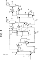
- FIG. 1 is a schematic diagram of an acid gas removal apparatus.
- the invention relates to an acid gas removal method in accordance with claim 1.
- An acid gas removal apparatus disclosed herein includes: an absorption tower; a first heater; a phase separation tank; a second heater; a regeneration tower; and a third heater.
- the absorption tower brings gas containing acid gas into contact with an acid gas absorbent composed of a solution containing a thermosensitive nitrogen-containing compound represented by the formula (1) and having a lower critical solution temperature at a predetermined temperature to absorb the acid gas into the acid gas absorbent and to remove the acid gas from the gas.
- the first heater heats the acid gas absorbent that has absorbed the acid gas to the lower critical solution temperature of the solution or more.
- the phase separation tank phase-separates the heated acid gas absorbent into a rich absorbent phase and a lean absorbent phase, and the lean absorbent phase contains more of the thermosensitive nitrogen-containing compound than the rich absorbent phase.
- the second heater heats the rich absorbent phase.
- the regeneration tower releases the acid gas in the rich absorbent phase.
- the third heater is provided at the regeneration tower and heats the rich absorbent phase.
- R 1 is a hydroxyalkyl group
- R 2 is a non-substituted cyclic alkyl group whose carbon number is 3 to 10
- R 3 is a hydrogen atom or a non-substituted alkyl group.
- An acid gas removal method includes: an absorption process, a phase separation process; and a regeneration process.
- gas containing acid gas and an acid gas absorbent composed of a solution containing a thermosensitive nitrogen-containing compound represented by the formula (1) and having a lower critical solution temperature are brought into contact at a predetermined temperature to absorb the acid gas into the acid gas absorbent and to remove the acid gas from the gas.
- the acid gas absorbent that has absorbed the acid gas is heated to the lower critical solution temperature of the solution or more to phase-separate the heated acid gas absorbent into a rich absorbent phase and a lean absorbent phase, and the lean absorbent phase contains more of the thermosensitive nitrogen-containing compound than the rich absorbent phase.
- the rich absorbent phase is heated to release the acid gas in the rich absorbent phase.
- an apparatus to separate and recover CO 2 that is the acid gas is installed to be added to an existing power generation facility, and so on, and therefore, it is required to decrease an operation cost of the apparatus as much as possible.
- thermal energy corresponding to 20% to 30% of a power generation amount is required for the separation and recovery of CO 2 , and it is desired to decrease the thermal energy required for the separation and recovery.
- CO 2 is released from an absorbent that has absorbed CO 2 to regenerate the absorbent, a lot of thermal energy is required, and therefore, it is important how to minimize the thermal energy.
- the present inventors focused on a point that water is contained approximately 50 mass% in the acid gas absorbent that has absorbed the acid gas, so evaporation of water occurs when the acid gas is released from the acid gas absorbent at the regeneration, and a lot of thermal energy as heat of evaporation of water is required to regenerate the acid gas absorbent.
- An acid gas removal apparatus and an acid gas removal method of a liquid-liquid phase separation type are attained in which a solution containing a thermosensitive nitrogen-containing compound represented by the formula (1) and having a lower critical solution temperature (LCST) is used as an acid gas absorbent, the lower critical solution temperature of the solution is utilized, the acid gas absorbent that has absorbed the acid gas is set to be a temperature of the lower critical solution temperature or more, and thereby, phase separation is performed into a rich absorbent phase in which an acid gas concentration is high and a lean absorbent phase in which the acid gas concentration is low, and thereafter, the rich absorbent phase is regenerated.
- LCST lower critical solution temperature
- FIG. 1 is a schematic diagram of the acid gas removal apparatus according to the embodiment.
- An acid gas removal apparatus 1 illustrated in FIG. 1 is an apparatus for separating and recovering acid gas in gas containing the acid gas, such as CO 2 gas and hydrogen sulfide gas, in exhaust combustion gas and so on generated from facilities using fossil fuels such as a thermal power station by using an acid gas absorbent.
- the acid gas removal apparatus 1 is explained while using a case when the acid gas is CO 2 as an example unless otherwise specified, but it is not limited thereto.
- the acid gas removal apparatus 1 includes an absorption tower 2, a heat exchanger 7 as a first heater, a phase separation tank 3, a heat exchanger 37 as a second heater, a regeneration tower 4, and a heater 25 as a third heater.
- gas containing acid gas and an acid gas absorbent are brought into gas-liquid contact at a predetermined temperature, preferably at lower than a later-described LCST, the acid gas in the gas is absorbed by the acid gas absorbent, to remove the acid gas from the gas.
- the acid gas absorbent that has absorbed the acid gas is heated.
- the acid gas absorbent heated at the heat exchanger 7 is phase-separated into a rich absorbent phase and a lean absorbent phase whose content of the thermosensitive nitrogen-containing compound is higher than the rich absorbent phase.
- the rich absorbent phase is heated.
- the rich absorbent phase is heated, preferably heated at a temperature higher than the heat exchanger 37, the acid gas is separated from the rich absorbent phase, the separated acid gas is recovered, and the acid gas absorbent is regenerated.
- the heater 25 heating the rich absorbent phase in the regeneration tower 4 is provided at a lower part of the regeneration tower 4.
- a gas supply port 5 which introduces the gas containing the acid gas being a process object is provided at a lower part of the absorption tower 2.
- a discharge port 6 discharging the acid gas absorbent in the absorption tower 2 is provided at a tower bottom part of the absorption tower 2.
- a liquid transfer pipe 8 which transfers the acid gas absorbent to the phase separation tank 3 via the heat exchanger 7 is connected to the discharge port 6.
- a gas discharge port 9 discharging the gas after the acid gas is removed, and a supply port 10 charging a new acid gas absorbent and supplying the acid gas absorbent which is separated or regenerated at the phase separation tank 3 and the regeneration tower 4 are respectively provided at an upper part of the absorption tower 2.
- a reflux water line 11 which cools vapor generated at the phase separation tank 3 to make it flow back to the absorption tower 2 is connected to the absorption tower 2.
- a predetermined amount of the new acid gas absorbent is charged into the absorption tower 2, for example, at an operation start time of the acid gas removal apparatus 1, and after that, it is cyclically used while being used and regenerated. In the case where the acid gas absorbent in the absorption tower 2 does not satisfy a predetermined amount, a necessary amount of the new acid gas absorbent is appropriately charged additionally therein.
- the supply port 10 supplying the acid gas absorbent to the absorption tower 2 is connected to an absorbent cooler 13 by a liquid transfer pipe 12. Further, the absorbent cooler 13 is connected to an outlet port 15 of a lean absorbent phase 33 provided at the phase separation tank 3 via a liquid transfer pipe 32 and a liquid transfer pipe 14. After the lean absorbent phase 33 in the phase separation tank 3 is discharged from the outlet port 15, the lean absorbent phase 33 is transferred to the absorption tower 2 via the liquid transfer pipe 14, a liquid transfer pipe 32 and the liquid transfer pipe 12. At this time, at the heat exchanger 7, the lean absorbent phase 33 is heat-exchanged for the acid gas absorbent absorbing the acid gas that is transferred via the liquid transfer pipe 8.
- the absorbent cooler 13 is connected to an outlet port 17 provided at the lower part of the regeneration tower 4 via the liquid transfer pipe 32, the heat exchanger 7, the heat exchanger 37 and a liquid transfer pipe 16.
- the rich absorbent phase 34 in the phase separation tank 3 is heated at the heat exchanger 37 to be transfer to a supply port 26 provided at the regeneration tower 4.
- a pump 18 is interposed, and the acid gas absorbent regenerated in the regeneration tower 4 and the lean absorbent phase 33 discharged from the phase separation tank 3 are joined with each other to be transferred to the absorption tower 2.
- the acid gas absorbent which is separated or regenerated at the phase separation tank 3 and the regeneration tower 4 is supplied to the absorption tower 2 via the absorbent cooler 13.
- a discharge port 35 which discharges the CO 2 separated from the acid gas absorbent in the phase separation tank 3 and the vapor generated by the heating out of the phase separation tank 3 is provided.
- the phase separation tank 3 is connected to a reflux cooling mechanism which separates CO 2 and water via the discharge port 35.
- the reflux cooling mechanism includes a reflux cooler 19 which cools the CO 2 gas containing vapor discharged from the phase separation tank 3, a reflux drum 20 which houses the cooled CO 2 and water, the reflux water line 11 which transfers the reflux water from the reflux drum 20 to the absorption tower 2, and a reflux water pump 21 which is interposed in the reflux water line 11.
- a recovery carbon dioxide line 22 recovering CO 2 from which the vapor is removed is connected to the reflux drum 20.
- the reflux water line 11 may be directly connected to the absorption tower 2, or may be connected to the liquid transfer pipe 12.
- An outlet port 23 which discharges a rich absorbent phase 34 is provided at a lower part of the phase separation tank 3.
- the phase separation tank 3 may include a heater which heats the acid gas absorbent in the phase separation tank 3.
- a discharge port 36 which discharges the CO 2 separated from the acid gas absorbent in the regeneration tower 4 and the vapor generated by the heating out of the regeneration tower 4 is provided.
- the regeneration tower 4 is connected to a reflex cooling mechanism similar to the reflux cooling mechanism provided at the phase separation tank 3, namely, such a reflux cooling mechanism including a reflux cooler 27, a reflux drum 28, a reflux water line 30, and a reflux water pump 29 via the discharge port 36.
- Reflux water in the reflux drum 28 is refluxed to the regeneration tower 4 by the reflux water line 30.
- a recover carbon dioxide line 31 recovering CO 2 from which the vapor is removed is connected to the reflux drum 28.
- the acid gas absorbent composed of the solution containing the thermosensitive nitrogen-containing compound and having the lower critical solution temperature is separated into two phases whose thermosensitive nitrogen-containing compound concentrations are different from each other at a temperature of the lower critical solution temperature or more, namely, into the rich absorbent phase and the lean absorbent phase.
- the rich absorbent phase is a phase whose concentration of the thermosensitive nitrogen-containing compound is low and whose CO 2 absorption amount is large between the two phases into which the acid gas absorbent absorbing the acid gas is separated as described above.
- the lean absorbent phase is a phase whose concentration of the thermosensitive nitrogen-containing compound is high and whose CO 2 absorption amount is small compared to the rich absorbent phase constituting another phase between the above-described two phases.
- the acid gas absorbent used in the embodiment is a chemical absorbent to absorb and recover acid gas such as CO 2 gas and hydrogen sulfide gas in the gas containing the acid gas.
- the acid gas absorbent of the embodiment contains the thermosensitive nitrogen-containing compound described below.
- the thermosensitive nitrogen-containing compound used in the embodiment is a compound represented by the following formula (1) (hereinafter, to be referred to as a thermosensitive nitrogen-containing compound (A)).
- the thermosensitive nitrogen-containing compound (A) is a compound which exhibits thermosensitivity in solubility with water and has an acid gas absorption property.
- R 1 is a hydroxyalkyl group
- R 2 is a non-substituted cyclic alkyl group whose carbon number is 3 to 10
- R 3 is a hydrogen atom or a non-substituted alkyl group.
- thermosensitive nitrogen-containing compound (A) has the lower critical solution temperature. Namely, the thermosensitive nitrogen-containing compound (A) exhibits water-solubility at less than the LCST and exhibits non-water-solubility at the LCST or more.
- water-solubility means that it is soluble in water, and specifically, means to be dissolved for 0.3 parts by mass or more relative to 1 part by mass of water.
- the LCST indicates a temperature when a liquid with one liquid phase is phase-separated into two liquid phases by an increase of a temperature.
- the solution of the thermosensitive nitrogen-containing compound (A) used in the embodiment has a characteristic exhibiting compatibility at less than the LCST and non-compatibility at the LCST or more, namely a characteristic causing the phase separation (phase separation property).
- the acid gas absorbent that has absorbed the acid gas is heated to the LCST or more as described later, and thereby, it is possible to phase-separate the acid gas absorbent into the rich absorbent phase whose acid gas concentration is high and the lean absorbent phase whose acid gas concentration is low compared to the rich absorbent phase.
- the lean absorbent phase is in a state in which the acid gas is fully removed even if the lean absorbent phase is not heated, and therefore, the lean absorbent phase is able to be reused as the acid gas absorbent in the absorption tower as it is without heating.
- the rich absorbent phase is heated to be regenerated, and thereby, it is possible to decrease an amount of the acid gas absorbent to be heated.
- R 1 is a hydroxyalkyl group, and mainly imparts a hydrophilic property to the thermosensitive nitrogen-containing compound (A).
- the alkyl group constituting R 1 is a straight chain or a branched chain.
- the number of hydroxy group of R 1 is not particularly limited as long as the number is one or more, and a binding site of the hydroxy group to the alkyl group is not also particularly limited.
- the number and the binding site of the hydroxy group of R 1 may be appropriately selected depending on the LCST, the phase separation property of the solution, and the acid gas absorption property.
- the carbon number of R 1 is preferably 2 to 4, and R 1 is more preferably a hydroxyethyl group, a 2-hydroxypropyl group, a 3-hydroxypropyl group, or 2,3-dihydroxypropyl group, and further preferably a hydroxyethyl group from viewpoints of the acid gas absorption property and the phase separation property.
- R 2 is a non-substituted cyclic alkyl group whose carbon number is 3 to 10, and more preferably the non-substituted cyclic alkyl group whose carbon number is 3 to 8.
- Various reaction products are generated by a reaction of the thermosensitive nitrogen-containing compound (A) and the acid gas, and thereby, the acid gas absorbent absorbs the acid gas.
- the thermosensitive nitrogen-containing compound (A) has a steric hindrance
- the steric hindrance of the thermosensitive nitrogen-containing compound (A) largely affects the kinds of the generated reaction products.
- thermosensitive nitrogen-containing compound (A) when the thermosensitive nitrogen-containing compound (A) absorbs CO 2 , the steric hindrance of the thermosensitive nitrogen-containing compound (A) advantageously acts on generation of bicarbonate ions. Heat of the reaction to generate the bicarbonate ions from the thermosensitive nitrogen-containing compound (A) and CO 2 is relatively low. Accordingly, the thermosensitive nitrogen-containing compound (A) has a proper steric hindrance, and thereby, it is possible to decrease the heat of reaction in which the acid gas absorbent absorbs the CO 2 and to improve the CO 2 absorption property.
- R 2 imparts the proper steric hindrance to the thermosensitive nitrogen-containing compound (A), and thereby, R 2 functions to improve the acid gas absorption property of the acid gas absorbent.
- R 2 is the cyclic alkyl group, and thereby, it is possible to have a structure whose steric hindrance is large to have an excellent acid gas absorption property compared to a case when, for example, R 2 is a chain alkyl group.
- a cyclopropyl group, a cyclobutyl group, a cyclopentyl group, and a cyclohexyl group are preferable among the above-described cyclic alkyl group from the viewpoints of the acid gas absorption property and the phase separation property.
- the cyclopentyl group and the cyclohexyl group are preferable, and in this case, it is possible to impart high steric hindrance to the thermosensitive nitrogen-containing compound (A) while the thermosensitive nitrogen-containing compound (A) keeps fine solubility for water as a solvent. Accordingly, at the absorption of the acid gas, it is possible to increase an effect of decreasing the heat of reaction and to obtain the excellent acid gas absorption property.
- R 3 is a hydrogen atom or a non-substituted alkyl group.
- R 3 is able to be appropriately selected in accordance with the acid gas absorption property and the phase separation property required for the thermosensitive nitrogen-containing compound (A), for example, in consideration of an interaction and so on with physical properties exhibited by R 1 and R 2 .
- R 3 is preferably the hydrogen atom or the alkyl group whose carbon number is 1 to 3, and more preferably the hydrogen atom or a methyl group.
- thermosensitive nitrogen-containing component (A) exhibits the fine phase separation property while exhibiting fine acid gas absorption property if R 3 is the methyl group.
- thermosensitive nitrogen-containing compound (A) from the viewpoints of the phase separation property and the acid gas absorption property, there are suitably used, 2-(cyclopentylamino)ethanol, 1-(cyclopentylamino)-2-propanol, 3-(cyclopentylamino)-1,2-propanediol, 4-(cyclopentylamino)-1-butanol, 2-(cyclohexylamino)ethanol, 1-(cyclohexylamino)-2-propanol, 3-(cyclohexylamino)-1,2-propanediol, 2-(cycloheptylamino)ethanol, 1-(cycloheptylamino)-2-propanol, 1-(cycloheptylamino)-1,2-propanediol, 2-(cyclooctylamino)ethanol, 3-(cyclooctylamino)-1,2-propanediol, 3-(cyclohexylamino)
- thermosensitive nitrogen-containing component (A) 2-(N-cyclopentyl-N-methylamino)ethanol, 2-(N-cyclohexyl-N-methylamino)ethanol, 2-(N-cyclooctyl-N-methylamino)ethanol, and 3-(N-cyclohexyl-N-methylamino)-1-propanol are more preferable.
- the LCST is preferably 50°C or more and 100°C or less, and more preferably 50°C or more and 80°C or less.
- a heating temperature of the acid gas absorbent when the phase separation into the rich absorbent phase and the lean absorbent phase occurs becomes high, and energy used to release the acid gas increases.
- the LCST becomes lower than 50°C, the acid gas absorbent absorbs the acid gas under a phase separated state, and therefore, an absorption efficiency of the acid gas is lowered.
- the acid gas absorbent composed of the solution of the thermosensitive nitrogen-containing compound (A) is able to release a part of the absorbed acid gas from the acid gas absorbent at a relatively low temperature, for example, even at approximately 50°C. Therefore, when the LCST exceeds 100°C, it is estimated that a major part of the absorbed acid gas that has been absorbed at the phase separation is released, and after the phase separation, it is not necessary to remove the acid gas from the rich absorbent phase. Namely, there is little difference from the conventional method in which a whole of the acid gas absorbent is heated to release the acid gas, and there is a possibility in which an advantage to decrease the energy required for the release of the acid gas disappears compared to the conventional method.
- the acid gas absorbent of the embodiment is prepared by dissolving the above-described thermosensitive nitrogen-containing compound (A) in water as a solvent.
- the water is not particularly limited, and mainly ion-exchange water is used.
- thermosensitive nitrogen-containing compound (A) in the acid gas absorbent is 15 mass% to 50 mass%, and preferably 20 mass% to 50 mass% relative to a whole quantity of the acid gas absorbent.
- an absorption amount and a desorption amount of the acid gas per unit volume of the acid gas absorbent are larger and an absorption rate and a desorption rate of the acid gas are faster as a concentration of the amine component is higher.
- this is preferable in view of decreasing an energy consumption amount and a size of a plant facility, and improving process efficiency.
- thermosensitive nitrogen-containing compound (A) As the content of the thermosensitive nitrogen-containing compound (A) relative to the whole quantity of the acid gas absorbent is 50 mass% or less, phenomena such as the increase in viscosity of the acid gas absorbent and the deterioration of the function of water as the activator are not recognized. Further, by setting the content of the thermosensitive nitrogen-containing compound (A) to 15 mass% or more, it is possible to obtain sufficient absorption amount and absorption rate for the acid gas absorbent, and to obtain excellent process efficiency.
- thermosensitive nitrogen-containing compound (A) relative to the whole quantity of the acid gas absorbent is 15 mass% to 50 mass%, not only the CO 2 absorption amount and the CO 2 absorption rate are high but also the CO 2 desorption amount and the CO 2 desorption rate are high in the acid gas absorbent used for the CO 2 recovery. Therefore, it is advantageous in that the recovery of CO 2 can be performed efficiently.
- the acid gas absorbent of the embodiment further contains one kind or more of compounds selected from amino alcohols, heterocyclic amines and polyvalent amines as a reaction accelerator.
- the above-described reaction accelerators are each water soluble compounds having an amino group in molecules.
- a nitrogen atom constituting the amino group is bound to CO 2 to form a carbamate ion in a reaction with CO 2 , and thereby, it contributes to the improvement of the absorption rate at an initial stage of the reaction between the thermosensitive nitrogen-containing compound and the acid gas.
- the nitrogen atom of the secondary amino group has a role of converting the CO 2 bound to the nitrogen atom into a bicarbonate ion (HCO 3 - ), and contributes to the improvement of the rate at a latter half stage of the reaction. Accordingly, the above-described reaction accelerator is contained, and thereby, it is possible to improve the acid gas absorption property of the acid gas absorbent.
- the amino alcohols in the embodiment are amines having one or more hydroxyalkyl groups as a substituent bound to the nitrogen atom, and it is not particularly limited as long as the amino alcohols are compounds exhibiting a reaction acceleration property and the water-solubility acting on the improvement in the acid gas absorption rate.
- the amino alcohols are preferably a primary or secondary amine, and in this case, it is preferable to have two hydroxyalkyl groups or the hydroxyalkyl group and the alkyl group as the substituents.
- the alkyl group and the hydroxyalkyl group may each be a straight chain or a branched chain.
- the carbon number of each of the alkyl group and the hydroxyalkyl group is preferably 1 to 8, and more preferably 2 to 4.
- these substituents may be the same or different.
- amino alcohols as described above there can be used, for example, monoethanolamine, 2-amino-2-methyl-1-propanol, 2-amino-2-methyl-1,3-dipropanol, methylaminoethanol, ethylaminoethanol, propylaminoethanol, diethanolamine, 2-methylaminoethanol, 2-(ethylamino)ethanol, 2-propylaminoethanol, n-butylaminoethanol, 2-(isopropylamino)ethanol, 3-ethylaminopropanol, and so on.
- amino alcohols 2-(isopropylamino)ethanol, 2-(ethylamino)ethanol, and 2-amino-2-methyl-1-propanol are preferable.
- the heterocyclic amines in the embodiment are a saturated heterocyclic amine that is composed of one to four carbon atoms and one to three nitrogen atoms or a derivative thereof, and are compounds exhibiting the water-solubility.
- the heterocyclic amine derivative is a compound having one or two or more substituents on a heterocycle of the heterocyclic amine.
- the substituent is preferably one kind or more selected from the hydroxy group, the alkyl group, the hydroxyalkyl group, and an aminoalkyl group.
- the carbon number of each of these substituents is preferably 1 to 3, and the methyl group, the ethyl group, a hydroxymethyl group, the hydroxyethyl group, an aminomethyl group, and an aminoethyl group are more preferable.
- a binding site of the substituent is not particularly limited, and it may be bound to any of the carbon atoms and the nitrogen atoms of the heterocycle. When the heterocyclic amine derivative has a plurality of substituents, these substituents may be the same or different.
- the heterocyclic amine is generally a compound having volatility.
- the volatility of the heterocyclic amine derivative is suppressed by having the substituent at the heterocycle.
- the heterocyclic amine does not have the substituent at the carbon atom, and therefore, it is excellent in the reaction acceleration property compared to the heterocyclic amine derivative having the substituent. Accordingly, the heterocyclic amines may be appropriately selected from the above-described heterocyclic amines and the heterocyclic amine derivatives in accordance with properties required for the reaction accelerator.
- heterocyclic amines there can be used the heterocyclic amine such as azetidine, pyrrolidine, piperidine, hexahydro-1H-azepine, hexamethylenetetramine, piperazine, and derivatives thereof.
- azetidine derivatives there can be used 1-methylazetidine, 1-ethylazetidine, 2-methylazetidine, 2-azetidinemethanol, 2-(2-aminoethyl)azetidine, and so on.
- pyrrolidine derivatives there can be used 1-methylpyrrolidine, 2-methylpyrrolidine, 2-butylpyrrolidine, 2-pyrrolidinemethanol, 2-(2-aminoethyl)pyrrolidine, and so on.
- piperidine derivatives there can be used 1-methylpiperidine, 2-ethylpiperidine, 3-propylpiperidine, 4-ethylpiperidine, 2-piperidinemethanol, 3-piperidineethanol, 2-(2-aminoethyl)piperidine, and so on.
- piperazine derivatives there can be used 2-methylpiperazine, 2,5-dimethylpiperazine, 2,6-dimethylpiperazine, 1-methylpiperazine, 1-(2-hydroxyethyl)piperazine, 1-(2-aminoethyl)piperazine, and so on.
- the above-described piperazine and the piperazine derivatives are particularly desirable from viewpoints of improving the acid gas absorption amount and the absorption rate.
- the polyvalent amines are each alkylamine which has a total of two or more primary and/or secondary amino groups in one molecule, and it is not particularly limited as long as the polyvalent amines are water-soluble compounds.
- the polyvalent amines for example, water-soluble polyalkylpolyamine and alkylpolyamine in which the carbon number of the alkyl group is preferably 3 to 8 can be used.
- alkylpolyamine in which the carbon number of the alkyl group is preferably 3 to 8 there can be used propanediamine, butanediamine, pentamethylenediamine, hexamethylenediamine.
- water-soluble polyalkylpolyamine polyalkylpolyamine in which carbon chain of the above-described alkylpolyamine are polymerized can be used.
- polyvalent amines among the above, it is more preferable to be 1,3-propanediamine, 1,4-butanediamine, 1,3-pentamethylenediamine, 1,5-pentamethylenediamine, 1,6-hexamethylenediamine from viewpoints of improvement in the water-solubility and the reaction acceleration property.
- reaction accelerator one kind of the above-described compounds may be independently used, or two or more kinds may be used together.
- a content of the reaction accelerator is preferably 1 mass% to 15 mass% relative to the whole quantity of the acid gas absorbent. There is a possibility that the effect of improving the acid gas absorption rate cannot be fully obtained when the content of the reaction accelerator is less than 1 mass% relative to the whole quantity of the acid gas absorbent. When the content of the reaction accelerator exceeds 15 mass% relative to the whole quantity of the acid gas absorbent, there is a possibility that the reaction acceleration property decreases because the viscosity of the acid gas absorbent becomes excessively high.
- a nitrogen-containing compound other than the above-described reaction accelerator to improve the acid gas absorption property other compounds such as an anticorrosive of a phosphoric acid based material or the like to prevent corrosion of plant facilities, a defoamer of a silicone based material or the like to prevent effervescence, an antioxidant to prevent deterioration of the acid gas absorbent, a pH adjusting agent to adjust pH may be added to the acid gas absorbent within a range in which effects of the acid gas absorbent are not deteriorated.
- a pH value of the acid gas absorbent is preferably adjusted to 9 or more by adding the pH adjusting agent.
- the pH value of the acid gas absorbent is able to be adjusted as necessary depending on a kind, concentration, flow rate, or the like of the acid gas contained in the gas.
- the acid gas removal method of the embodiment includes: an absorption process; a phase separation process; and a regeneration process.
- an acid gas absorbent composed of a solution containing a thermosensitive nitrogen-containing compound (A) represented by the formula (1) and having a lower critical solution temperature and gas containing acid gas are brought into contact with each other at a predetermined temperature, the acid gas is absorbed by the acid gas absorbent to thereby remove the acid gas from the gas.
- the acid gas absorbent absorbing the acid gas obtained in the absorption process is heated to the lower critical solution temperature of the solution or more, and is phase separated into a rich absorbent phase and a lean absorbent phase whose content of the thermosensitive nitrogen-containing compound is higher than the rich absorbent phase.
- the rich absorbent phase obtained in the phase separation process is heated, and thereby, the acid gas in the rich absorbent phase is released and recovered.
- the acid gas removal method of the embodiment is explained below as for a case when the acid gas removal apparatus 1 illustrated in FIG. 1 is used.
- the gas containing the acid gas is introduced into the lower part of the absorption tower 2 via the gas supply port 5.
- a new acid gas absorbent is supplied from the supply port 10 at the upper part of the absorption tower 2 to be housed in the absorption tower 2.
- the gas containing the acid gas is brought into gas-liquid contact with the acid gas absorbent at a predetermined temperature, preferably less than the LCST in the absorption tower 2, and thereby, the acid gas in the gas is absorbed and removed by the acid gas absorbent.
- the gas after the acid gas is removed is discharged outside of the absorption tower 2 from the gas discharge port 9.
- the method to bring the gas into gas-liquid contact with the acid gas absorbent in the absorption tower 2 is not particularly limited.
- the method of the gas-liquid contact is performed by, for example, a method in which the gas is bubbled in the acid gas absorbent, a method in which the acid gas absorbent is atomized and sprayed in a flow of the gas (atomizing method, spraying method), a method in which the gas is brought into countercurrent contact with the acid gas absorbent in an absorption tower containing a filler made of a porcelain or a filler made of a metal net, or the like.
- a temperature of the acid gas absorbent in the absorption tower 2 is preferably less than the LCST, specifically the room temperature or more and 60°C or less, more preferably the room temperature or more and 50°C or less, further preferably approximately 20°C to 45°C.
- the acid gas absorption amount of the acid gas absorbent tends to increase as the temperature of the acid gas absorbent in the absorption tower 2 is lower, but energy to reduce the temperature of the acid gas absorbent is necessary, and therefore, a lower limit value of the temperature of the acid gas absorbent is determined by a gas temperature, a heat recovery target and so on in the process.
- a pressure in the absorption tower 2 in the absorption process is preferably the atmospheric pressure.
- the CO 2 absorption amount at 40°C of the acid gas absorbent containing 15 mass% to 50 mass% of the thermosensitive nitrogen-containing compound (A) is approximately 0.20 mol to 0.85 mol per 1 mol of the thermosensitive nitrogen-containing compound (A) contained in the acid gas absorbent.
- the CO 2 absorption rate per 1 mol of the thermosensitive nitrogen-containing compound (A) after a few minutes from the start of the absorption of CO 2 is approximately 0.006 mol/mol/min to 0.009 mol/mol/min in the acid gas absorbent containing 15 mass% to 50 mass% of the thermosensitive nitrogen-containing compound (A).
- the CO 2 absorption amount is a value of an inorganic carbon amount in the acid gas absorbent measured by an infrared gas concentration measurement device. Further, the CO 2 absorption rate is a value measured by using an infrared carbon dioxide sensor at the time after a few minutes from the start of the absorption of CO 2 .
- the acid gas absorbent that has absorbed the acid gas in the absorption tower 2 is heated at the heat exchanger 7, and then transferred to the phase separation tank 3.
- the acid gas absorbent is heated to be thereby phase-separated, and separated into two phases of an acid gas absorbent phase whose acid gas concentration is high (rich absorbent phase) and an acid gas absorbent phase whose acid gas concentration is lower than the rich absorbent phase (lean absorbent phase) to be housed in the phase separation tank 3.
- the acid gas absorbent which is regenerated from the rich absorbent phase at the regeneration tower 4 and the lean absorbent phase 33 from the phase separation tank 3, and the acid gas absorbent which has absorbed the acid gas in the absorption tower 2 are heat-exchanged, and thereby, the acid gas absorbent that has absorbed the acid gas is heated and the regenerated acid gas absorbent and the lean absorbent phase 33 are cooled.
- the acid gas absorbent which is regenerated at the regeneration tower 4 and the rich absorbent phase 34 from the phase separation tank 3 are heat-exchanged, and thereby, the rich absorbent phase 34 is heated and the regenerated acid gas absorbent is cooled.
- a temperature of the acid gas absorbent in the phase separation tank 3 (hereinafter, to be referred to as a tank temperature) is set to be the LCST or more of the solution of the thermosensitive nitrogen-containing compound (A).
- the tank temperature is preferably 50°C or more, more preferably 60°C or more, further preferably approximately 60°C to 100°C.
- the heating temperature of the acid gas absorbent in the phase separation process is preferably a heating temperature of the rich absorbent phase in a later-described regeneration process or less.
- the rich absorbent phase is supplied to the regeneration tower 4 from the supply port 26 provided at an upper part of the regeneration tower 4 by passing through a liquid transfer pipe 24 from the outlet port 23 provided at the lower part of the phase separation tank 3 in order to cyclically use (recycle) the remaining acid gas absorbent.
- the lean absorbent phase of the phase separation tank 3 passes the liquid transfer pipe 14, is transferred to the absorbent cooler 13, and then cooled there.
- the cooled lean absorbent phase is returned to the absorption tower 2 through the liquid transfer pipe 12, and cyclically used (recycled) as the acid gas absorbent again.
- the acid gas separated from the acid gas absorbent at the phase separation tank 3 is extracted from the discharge port 35 provided at the upper part of the phase separation tank 3 together with vapor generated at the phase separation tank 3, and is supplied to the reflux drum 20 via the reflux cooler 19.
- the mixed gas of the acid gas and vapor is cooled at the reflux cooler 19, and water generated by condensation of the vapor is returned to the absorption tower 2 by the reflux water pump 21 from the reflux drum 20 by passing through the reflux water line 11.
- the acid gas from which the vapor is removed is supplied to a process recovering the acid gas by the recovery carbon dioxide line 22.
- the reflux water line 11 is connected to the liquid transfer pipe 12, the water is transferred to the absorption tower 2 together with the regenerated acid gas absorbent via the liquid transfer pipe 12.
- the rich absorbent phase supplied to the regeneration tower 4 is flowed from the supply port 26 provided at the upper part of the regeneration tower 4 toward the lower part, and heated by the heater 25 (reboiler) provided at the lower part of the regeneration tower 4. During this process, the acid gas in the rich absorbent phase is released. The pure or high-concentration acid gas is thereby recovered, and the acid gas absorbent is regenerated.
- a distillation tower a plate tower, a spray tower, and a packed tower containing a filler made of a porcelain or a filler made of a metal net can be used.
- the rich absorbent phase is sprayed from the upper part of the regeneration tower 4, and thereby, it is possible to desorb the acid gas by spreading a liquid interface in the regeneration tower 4. It is thereby possible to isolate and release the acid gas from carbamate anion and bicarbonate ion bound to the thermosensitive nitrogen-containing compound (A).
- the heating temperature of the rich absorbent phase at the regeneration tower 4 is preferably the tank temperature or more. Specifically, the heating temperature of the rich absorbent phase is preferably 70°C or more, more preferably 80°C or more, and further preferably approximately 90°C to 120°C.
- the desorption amount of the acid gas increases as the heating temperature of the rich absorbent phase is higher, but energy required for the heating of the rich absorbent phase increases if the heating temperature is increased. Therefore, the heating temperature of the rich absorbent phase at the regeneration tower 4 is determined by the gas temperature, the heat recovery target, and so on in the process.
- the regeneration process at the regeneration tower 4 is performed under a condition in which a pressure in the regeneration tower 4 is preferably 1 atmosphere or more and 3 atmospheres or less, more preferably 1 atmosphere or more and 2 atmospheres or less from a viewpoint of suppressing evaporation of the water.
- the CO 2 desorption amount at 70°C of the acid gas absorbent containing 15 mass% to 50 mass% of the thermosensitive nitrogen-containing compound (A) is approximately 50% or more of the absorbed CO 2 .
- the acid gas absorbent regenerated at the regeneration tower 4 passes through the liquid transfer pipe 16 from the outlet port 17 provided at the lower part of the regeneration tower 4, is transferred to the heat exchanger 7 and the absorbent cooler 13 by the pump 18, and then returned to the absorption tower 2 from the liquid transfer pipe 12 together with the lean absorbent phase. Note that at the absorbent cooler 13, the regenerated acid gas absorbent is cooled to 30°C to 50°C.
- the acid gas separated from the acid gas absorbent at the regeneration tower 4 is extracted from the discharge port 36 provided at the upper part of the regeneration tower 4 together with the vapor generated at the regeneration tower 4, and is supplied to the reflux drum 28 via the reflux cooler 27.
- the mixed gas of the acid gas and vapor is cooled at the reflux cooler 27, and water generated by condensation of the vapor is returned to the regeneration tower 4 from the reflux drum 28 by the reflux water pump 29.
- the acid gas from which the vapor is removed is supplied to a process recovering the acid gas by the recovery carbon dioxide line 31.
- Purity of the acid gas recovered by the recovery carbon dioxide line 31 as stated above is extremely high, which is for example, approximately 95 vol% to 99 vol%.
- the pure acid gas or high-concentration acid gas is used as chemicals, synthetic raw materials of high polymer, a coolant for freezing foods, and so on.
- the processes of separating the acid gas from the acid gas absorbent and regenerating the acid gas absorbent are parts consuming the largest amount of energy. In these processes, approximately 50% to 80% of the energy consumed in all of the processes is consumed.
- the acid gas removal method of the embodiment it is possible in the phase separation process to separate approximately 50% or more of the acid gas in the acid gas absorbent at a temperature lower than the regeneration process, and therefore, it is possible to decrease the consumption energy at the regeneration process compared to the conventional technology. Therefore, it is possible to decrease the cost of the absorption and separation of the acid gas, and to advantageously perform the acid gas removal from the gas containing the acid gas from an economical viewpoint.
- the acid gas removal apparatus of the embodiment it is possible to perform the absorption and removal of the acid gas in low energy: by absorbing the acid gas into the acid gas absorbent which is excellent in the absorption property and desorption property for the acid gas at the absorption tower; phase-separating the acid gas absorbent to separate the rich absorbent phase whose acid gas concentration is high at the phase separation tank; and regenerating the rich absorbent phase separated from the acid gas absorbent at the regeneration tower.
- the embodiment it is possible to decrease the energy required to separate and regenerate the acid gas by using the acid gas absorbent according to the above-described embodiment. Therefore, it is possible to perform the removal of the acid gas from the gas containing the acid gas and the regeneration of the acid gas absorbent under an economically advantageous condition.
- An acid gas absorbent was prepared by dissolving 45 parts by mass of 2-(N-cyclopentyl-N-methylamino)ethanol and 5 parts by mass of piperazine in 50 parts by mass of water. Then, gas containing approximately 10 vol% of CO 2 gas at 40°C was aerated in the obtained acid gas absorbent at a flow rate of 0.5 L/min for approximately two hours to absorb the CO 2 gas into the acid gas absorbent. The total CO 2 gas absorption amount of the acid gas absorbent was 36 NL/L. After that, the acid gas absorbent containing the CO 2 gas was gradually heated to 80°C to phase-separate the acid gas absorbent into the rich absorbent phase and the lean absorbent phase.
- the volume ratio of the rich absorbent phase and the lean absorbent phase of the phase-separated acid gas absorbent was 4 to 6, and respective CO 2 gas absorption amounts were 21 NL/L, 10 NL/L. Further, the rich absorbent phase and the lean absorbent phase were separated from each other. The rich absorbent phase was only heated to 100°C, and then 20% of the CO 2 gas from among the absorbed total CO 2 gas absorption amount was released. As a result, it turned out that the acid gas absorbent released the CO 2 gas of 90% or more at 100°C from among the total CO 2 gas absorption amount which had been initially absorbed by the acid gas absorbent.
- the removal of CO 2 was performed under the same condition as EXAMPLE 1 except that 2-(N-cyclohexyl-N-methylamino)ethanol was used in place of 2-(N-cyclopentyl-N-methylamino)ethanol.
- the acid gas absorbent released the CO 2 gas of approximately 71% at 80°C from among the total CO 2 gas absorption amount which had been initially absorbed by the acid gas absorbent, and released the CO 2 gas of 90% or more at 100°C.
- the removal of CO 2 was performed under the same condition as EXAMPLE 1 except that 2-(N-cyclooctyl-N-methylamino)ethanol was used in place of 2-(N-cyclopentyl-N-methylamino)ethanol.
- the acid gas absorbent released the CO 2 gas of approximately 65% at 80°C from among the total CO 2 gas absorption amount which had been initially absorbed by the acid gas absorbent, and released the CO 2 gas of 90% or more at 100°C.
- the removal of CO 2 was performed under the same condition as EXAMPLE 1 except that 3-(N-cyclohexyl-N-methylamino)-1-propanol was used in place of 2-(N-cyclopentyl-N-methylamino)ethanol.
- the acid gas absorbent released the CO 2 gas of approximately 69% at 80°C from among the total CO 2 gas absorption amount which had been initially absorbed by the acid gas absorbent, and released the CO 2 gas of 90% or more at 100°C.
- the removal of CO 2 was performed under the same condition as EXAMPLE 1 except that 2-(N-butyl-N-methylamino)ethanol was used in place of 2-(N-cyclopentyl-N-methylamino)ethanol.
- the acid gas absorbent released the CO 2 gas of approximately 50% at 80°C from among the total CO 2 gas absorption amount which had been initially absorbed by the acid gas absorbent, and released the CO 2 gas of 80% at 100°C.
- the phase separation does not occur even at 100°C, and the release amount of the CO 2 gas was approximately 80%.
- the acid gas absorbent was able to release the CO 2 of 90% or more at the high temperature of 100°C from among the total CO 2 gas absorption amount which had been initially absorbed by the acid gas absorbent, and to release the CO 2 of at least 65% or more even at 80°C. Further, it is possible to recover the CO 2 gas of 90% or more even if the total quantity of the acid gas absorbent is not heated, and therefore, it turned out that the regeneration energy of the acid gas absorbent is able to be reduced.
Landscapes
- Chemical & Material Sciences (AREA)
- Engineering & Computer Science (AREA)
- Analytical Chemistry (AREA)
- General Chemical & Material Sciences (AREA)
- Oil, Petroleum & Natural Gas (AREA)
- Chemical Kinetics & Catalysis (AREA)
- Environmental & Geological Engineering (AREA)
- Health & Medical Sciences (AREA)
- Biomedical Technology (AREA)
- Life Sciences & Earth Sciences (AREA)
- Sustainable Development (AREA)
- Gas Separation By Absorption (AREA)
- Treating Waste Gases (AREA)
- Organic Low-Molecular-Weight Compounds And Preparation Thereof (AREA)
Description
- Embodiments described herein relate generally to an acid gas removal method.
- In recent years, a greenhouse effect resulting from an increase in carbon dioxide (CO2) concentration has been pointed out as a cause of global warming phenomena, and there is an urgent need to devise an international countermeasure to protect environment in a global scale. Industrial activities have a large responsibility as a generation source of CO2, and there is a trend to suppress discharge of CO2.
- As technologies to suppress the increase of the concentration of acid gas, typically, CO2, there are a development of energy saving products, a separation and recovery technology of discharged acid gas, technologies to use the acid gas as a resource and to isolate and store the acid gas, a switching to alternate energies such as natural energy, atomic energy, and so on which do not discharge the acid gas, and so on. As the separation and recovery technology of the acid gas, there are an absorption process, a suction process, a membrane separation process, a cryogenic process, and so on. Among them, the absorption process is suitable for processing a large amount of gas, and its application in a factory and a power station is considered.
- In particular, at facilities such as a thermal power station using fossil fuels such as coal, coal oil, and natural gas, a method in which exhaust combustion gas generated when the fossil fuel is burned is brought into contact with a chemical absorbent, and thereby CO2 in the exhaust combustion gas is removed and recovered, and further a method of storing the recovered CO2 are performed. Further, there is proposed to remove acid gas such as hydrogen sulfide (H2S) other than CO2 by using the chemical absorbent.
- As the chemical absorbent used in the absorption process, amino alcohols typified by monoethanolamine (MEA) have been used because MEA is economical and it is easy to increase a removal apparatus in size in the absorption process. Further, a study on a chemical absorbent using the amino alcohols having structural steric hindrance has been tried because selectivity for acid gas is very high and energy required for regeneration of the absorbent (hereinafter, to be referred to as "regeneration energy") is small. In this case, for example, gas containing carbon dioxide gas is brought into contact with an alkanolamine solution in an absorption tower to absorb the carbon dioxide gas, and thereafter, a whole quantity of the carbon dioxide gas absorbing liquid is heated, and the carbon dioxide gas is desorbed and recovered at a desorption tower.
- As stated above, though a lot of attempts to reduce the regeneration energy of the absorbent are tried by using amino alcohols for the chemical absorbent, a chemical absorbent and a regeneration method enabling further reduction in the regeneration energy have been required.
- As the regeneration method to lower the regeneration energy of the absorbent, a method in which the chemical absorbent that has absorbed CO2 gas is phase-separated into solid and liquid (solid-liquid phase separation) or phase-separated into liquid and liquid (liquid-liquid phase separation), to regenerate a phase whose CO2 concentration is high has been studied. As a regeneration method in the solid-liquid phase separation, a method to form a solid reaction product by absorbing the CO2 gas has been proposed. However, the solid reaction product is difficult to be transferred to a regeneration tower compared to a liquid absorbent that has absorbed the CO2 gas. As a regeneration method in the liquid-liquid phase separation, a method in which an amine compound dissolved in a non-water-soluble solvent is reacted with the CO2 gas is known, and where the CO2 gas is absorbed by the amine compound dissolved in a non-water-soluble organic solvent or a water-soluble amine compound.
- Further, as the regeneration method in the liquid-liquid phase separation, a method using a demixing absorbing liquid having a characteristic of being divided when an absorbing liquid containing an acidic compound is heated has been proposed. In this method, after the acid gas absorption, an acid gas absorbing liquid is distilled, a part of the acid gas absorbing liquid is separated into two phases of a fraction rich in the acidic compound and a fraction lean in the acidic compound, the fraction rich in the acidic compound is distilled again to regenerate the absorbing liquid, to thereby suppress energy necessary for regeneration of the absorbing liquid.
-
US 2009/199709 A1 relates to of a method of deacidizing a gaseous effluent. -
EP 2468385 A2 relates to an acid gas absorbent, an acid gas removal device, and an acid gas removal method using the acid gas absorbent. -
FIG. 1 is a schematic diagram of an acid gas removal apparatus. - The invention relates to an acid gas removal method in accordance with
claim 1. - An acid gas removal apparatus disclosed herein includes: an absorption tower; a first heater; a phase separation tank; a second heater; a regeneration tower; and a third heater. The absorption tower brings gas containing acid gas into contact with an acid gas absorbent composed of a solution containing a thermosensitive nitrogen-containing compound represented by the formula (1) and having a lower critical solution temperature at a predetermined temperature to absorb the acid gas into the acid gas absorbent and to remove the acid gas from the gas. The first heater heats the acid gas absorbent that has absorbed the acid gas to the lower critical solution temperature of the solution or more. The phase separation tank phase-separates the heated acid gas absorbent into a rich absorbent phase and a lean absorbent phase, and the lean absorbent phase contains more of the thermosensitive nitrogen-containing compound than the rich absorbent phase. The second heater heats the rich absorbent phase. The regeneration tower releases the acid gas in the rich absorbent phase. The third heater is provided at the regeneration tower and heats the rich absorbent phase.

- An acid gas removal method according to an embodiment includes: an absorption process, a phase separation process; and a regeneration process. In the absorption process, gas containing acid gas and an acid gas absorbent composed of a solution containing a thermosensitive nitrogen-containing compound represented by the formula (1) and having a lower critical solution temperature are brought into contact at a predetermined temperature to absorb the acid gas into the acid gas absorbent and to remove the acid gas from the gas. In the phase separation process, the acid gas absorbent that has absorbed the acid gas is heated to the lower critical solution temperature of the solution or more to phase-separate the heated acid gas absorbent into a rich absorbent phase and a lean absorbent phase, and the lean absorbent phase contains more of the thermosensitive nitrogen-containing compound than the rich absorbent phase. In the regeneration process, the rich absorbent phase is heated to release the acid gas in the rich absorbent phase.
- For example, an apparatus to separate and recover CO2 that is the acid gas is installed to be added to an existing power generation facility, and so on, and therefore, it is required to decrease an operation cost of the apparatus as much as possible. According to investigation results of the present inventors up to now, thermal energy corresponding to 20% to 30% of a power generation amount is required for the separation and recovery of CO2, and it is desired to decrease the thermal energy required for the separation and recovery. In particular, when CO2 is released from an absorbent that has absorbed CO2 to regenerate the absorbent, a lot of thermal energy is required, and therefore, it is important how to minimize the thermal energy.
- The present inventors focused on a point that water is contained approximately 50 mass% in the acid gas absorbent that has absorbed the acid gas, so evaporation of water occurs when the acid gas is released from the acid gas absorbent at the regeneration, and a lot of thermal energy as heat of evaporation of water is required to regenerate the acid gas absorbent. An acid gas removal apparatus and an acid gas removal method of a liquid-liquid phase separation type are attained in which a solution containing a thermosensitive nitrogen-containing compound represented by the formula (1) and having a lower critical solution temperature (LCST) is used as an acid gas absorbent, the lower critical solution temperature of the solution is utilized, the acid gas absorbent that has absorbed the acid gas is set to be a temperature of the lower critical solution temperature or more, and thereby, phase separation is performed into a rich absorbent phase in which an acid gas concentration is high and a lean absorbent phase in which the acid gas concentration is low, and thereafter, the rich absorbent phase is regenerated.
- An acid gas removal apparatus is explained with reference to
FIG. 1. FIG. 1 is a schematic diagram of the acid gas removal apparatus according to the embodiment. An acidgas removal apparatus 1 illustrated inFIG. 1 is an apparatus for separating and recovering acid gas in gas containing the acid gas, such as CO2 gas and hydrogen sulfide gas, in exhaust combustion gas and so on generated from facilities using fossil fuels such as a thermal power station by using an acid gas absorbent. Hereinafter, the acidgas removal apparatus 1 is explained while using a case when the acid gas is CO2 as an example unless otherwise specified, but it is not limited thereto. - The acid
gas removal apparatus 1 includes anabsorption tower 2, a heat exchanger 7 as a first heater, a phase separation tank 3, aheat exchanger 37 as a second heater, aregeneration tower 4, and aheater 25 as a third heater. At theabsorption tower 2, gas containing acid gas and an acid gas absorbent are brought into gas-liquid contact at a predetermined temperature, preferably at lower than a later-described LCST, the acid gas in the gas is absorbed by the acid gas absorbent, to remove the acid gas from the gas. At the heat exchanger 7, the acid gas absorbent that has absorbed the acid gas is heated. At the phase separation tank 3, the acid gas absorbent heated at the heat exchanger 7 is phase-separated into a rich absorbent phase and a lean absorbent phase whose content of the thermosensitive nitrogen-containing compound is higher than the rich absorbent phase. At theheat exchanger 37 as a second heater, the rich absorbent phase is heated. At theregeneration tower 4, the rich absorbent phase is heated, preferably heated at a temperature higher than theheat exchanger 37, the acid gas is separated from the rich absorbent phase, the separated acid gas is recovered, and the acid gas absorbent is regenerated. Theheater 25 heating the rich absorbent phase in theregeneration tower 4 is provided at a lower part of theregeneration tower 4. - A
gas supply port 5 which introduces the gas containing the acid gas being a process object is provided at a lower part of theabsorption tower 2. In addition, adischarge port 6 discharging the acid gas absorbent in theabsorption tower 2 is provided at a tower bottom part of theabsorption tower 2. Aliquid transfer pipe 8 which transfers the acid gas absorbent to the phase separation tank 3 via the heat exchanger 7 is connected to thedischarge port 6. - As it is described later, a gas discharge port 9 discharging the gas after the acid gas is removed, and a
supply port 10 charging a new acid gas absorbent and supplying the acid gas absorbent which is separated or regenerated at the phase separation tank 3 and theregeneration tower 4 are respectively provided at an upper part of theabsorption tower 2. In addition, areflux water line 11 which cools vapor generated at the phase separation tank 3 to make it flow back to theabsorption tower 2 is connected to theabsorption tower 2. Note that a predetermined amount of the new acid gas absorbent is charged into theabsorption tower 2, for example, at an operation start time of the acidgas removal apparatus 1, and after that, it is cyclically used while being used and regenerated. In the case where the acid gas absorbent in theabsorption tower 2 does not satisfy a predetermined amount, a necessary amount of the new acid gas absorbent is appropriately charged additionally therein. - The
supply port 10 supplying the acid gas absorbent to theabsorption tower 2 is connected to anabsorbent cooler 13 by aliquid transfer pipe 12. Further, theabsorbent cooler 13 is connected to anoutlet port 15 of a leanabsorbent phase 33 provided at the phase separation tank 3 via aliquid transfer pipe 32 and aliquid transfer pipe 14. After the leanabsorbent phase 33 in the phase separation tank 3 is discharged from theoutlet port 15, the leanabsorbent phase 33 is transferred to theabsorption tower 2 via theliquid transfer pipe 14, aliquid transfer pipe 32 and theliquid transfer pipe 12. At this time, at the heat exchanger 7, the leanabsorbent phase 33 is heat-exchanged for the acid gas absorbent absorbing the acid gas that is transferred via theliquid transfer pipe 8. Theabsorbent cooler 13 is connected to anoutlet port 17 provided at the lower part of theregeneration tower 4 via theliquid transfer pipe 32, the heat exchanger 7, theheat exchanger 37 and aliquid transfer pipe 16. The richabsorbent phase 34 in the phase separation tank 3 is heated at theheat exchanger 37 to be transfer to asupply port 26 provided at theregeneration tower 4. In theliquid transfer pipe 14, apump 18 is interposed, and the acid gas absorbent regenerated in theregeneration tower 4 and the leanabsorbent phase 33 discharged from the phase separation tank 3 are joined with each other to be transferred to theabsorption tower 2. As stated above, the acid gas absorbent which is separated or regenerated at the phase separation tank 3 and theregeneration tower 4 is supplied to theabsorption tower 2 via theabsorbent cooler 13. - At the upper part of the phase separation tank 3, a
discharge port 35 which discharges the CO2 separated from the acid gas absorbent in the phase separation tank 3 and the vapor generated by the heating out of the phase separation tank 3 is provided. The phase separation tank 3 is connected to a reflux cooling mechanism which separates CO2 and water via thedischarge port 35. The reflux cooling mechanism includes a reflux cooler 19 which cools the CO2 gas containing vapor discharged from the phase separation tank 3, areflux drum 20 which houses the cooled CO2 and water, thereflux water line 11 which transfers the reflux water from thereflux drum 20 to theabsorption tower 2, and areflux water pump 21 which is interposed in thereflux water line 11. A recoverycarbon dioxide line 22 recovering CO2 from which the vapor is removed is connected to thereflux drum 20. Thereflux water line 11 may be directly connected to theabsorption tower 2, or may be connected to theliquid transfer pipe 12. - An
outlet port 23 which discharges a richabsorbent phase 34 is provided at a lower part of the phase separation tank 3. The phase separation tank 3 may include a heater which heats the acid gas absorbent in the phase separation tank 3. - At a tower top part of the
regeneration tower 4, adischarge port 36 which discharges the CO2 separated from the acid gas absorbent in theregeneration tower 4 and the vapor generated by the heating out of theregeneration tower 4 is provided. Theregeneration tower 4 is connected to a reflex cooling mechanism similar to the reflux cooling mechanism provided at the phase separation tank 3, namely, such a reflux cooling mechanism including a reflux cooler 27, areflux drum 28, areflux water line 30, and areflux water pump 29 via thedischarge port 36. Reflux water in thereflux drum 28 is refluxed to theregeneration tower 4 by thereflux water line 30. A recovercarbon dioxide line 31 recovering CO2 from which the vapor is removed is connected to thereflux drum 28. - The acid gas absorbent composed of the solution containing the thermosensitive nitrogen-containing compound and having the lower critical solution temperature is separated into two phases whose thermosensitive nitrogen-containing compound concentrations are different from each other at a temperature of the lower critical solution temperature or more, namely, into the rich absorbent phase and the lean absorbent phase. In this embodiment, the rich absorbent phase is a phase whose concentration of the thermosensitive nitrogen-containing compound is low and whose CO2 absorption amount is large between the two phases into which the acid gas absorbent absorbing the acid gas is separated as described above. The lean absorbent phase is a phase whose concentration of the thermosensitive nitrogen-containing compound is high and whose CO2 absorption amount is small compared to the rich absorbent phase constituting another phase between the above-described two phases.
- The acid gas absorbent used in the embodiment is a chemical absorbent to absorb and recover acid gas such as CO2 gas and hydrogen sulfide gas in the gas containing the acid gas.
- The acid gas absorbent of the embodiment contains the thermosensitive nitrogen-containing compound described below. The thermosensitive nitrogen-containing compound used in the embodiment is a compound represented by the following formula (1) (hereinafter, to be referred to as a thermosensitive nitrogen-containing compound (A)). The thermosensitive nitrogen-containing compound (A) is a compound which exhibits thermosensitivity in solubility with water and has an acid gas absorption property.

- In the formula (1), R1 is a hydroxyalkyl group, R2 is a non-substituted cyclic alkyl group whose carbon number is 3 to 10, and R3 is a hydrogen atom or a non-substituted alkyl group.
- The solution containing the thermosensitive nitrogen-containing compound (A) has the lower critical solution temperature. Namely, the thermosensitive nitrogen-containing compound (A) exhibits water-solubility at less than the LCST and exhibits non-water-solubility at the LCST or more. Note that in this specification, the "water-solubility" means that it is soluble in water, and specifically, means to be dissolved for 0.3 parts by mass or more relative to 1 part by mass of water.
- Here, the LCST indicates a temperature when a liquid with one liquid phase is phase-separated into two liquid phases by an increase of a temperature. In other words, the solution of the thermosensitive nitrogen-containing compound (A) used in the embodiment has a characteristic exhibiting compatibility at less than the LCST and non-compatibility at the LCST or more, namely a characteristic causing the phase separation (phase separation property).
- In the embodiment, the acid gas absorbent that has absorbed the acid gas is heated to the LCST or more as described later, and thereby, it is possible to phase-separate the acid gas absorbent into the rich absorbent phase whose acid gas concentration is high and the lean absorbent phase whose acid gas concentration is low compared to the rich absorbent phase.
- In this phase separation process, a part of the acid gas in the acid gas absorbent is released from the acid gas absorbent. Further, the rich absorbent phase which is taken out after the phase separation is heated, and thereby, remaining acid gas in the rich absorbent phase is released from the rich absorbent phase. On the other hand, the lean absorbent phase is in a state in which the acid gas is fully removed even if the lean absorbent phase is not heated, and therefore, the lean absorbent phase is able to be reused as the acid gas absorbent in the absorption tower as it is without heating. As stated above, only the rich absorbent phase is heated to be regenerated, and thereby, it is possible to decrease an amount of the acid gas absorbent to be heated. Thereby, in the embodiment, it is possible to decrease the energy required for the separation and recovery of the acid gas compared to a conventional method in which a whole quantity of the acid gas absorbent is heated.
- In the formula (1), R1 is a hydroxyalkyl group, and mainly imparts a hydrophilic property to the thermosensitive nitrogen-containing compound (A). The alkyl group constituting R1 is a straight chain or a branched chain. The number of hydroxy group of R1 is not particularly limited as long as the number is one or more, and a binding site of the hydroxy group to the alkyl group is not also particularly limited. The number and the binding site of the hydroxy group of R1 may be appropriately selected depending on the LCST, the phase separation property of the solution, and the acid gas absorption property. The carbon number of R1 is preferably 2 to 4, and R1 is more preferably a hydroxyethyl group, a 2-hydroxypropyl group, a 3-hydroxypropyl group, or 2,3-dihydroxypropyl group, and further preferably a hydroxyethyl group from viewpoints of the acid gas absorption property and the phase separation property.
- In the formula (1), R2 is a non-substituted cyclic alkyl group whose carbon number is 3 to 10, and more preferably the non-substituted cyclic alkyl group whose carbon number is 3 to 8. Various reaction products are generated by a reaction of the thermosensitive nitrogen-containing compound (A) and the acid gas, and thereby, the acid gas absorbent absorbs the acid gas. When the thermosensitive nitrogen-containing compound (A) has a steric hindrance, the steric hindrance of the thermosensitive nitrogen-containing compound (A) largely affects the kinds of the generated reaction products. For example, when the thermosensitive nitrogen-containing compound (A) absorbs CO2, the steric hindrance of the thermosensitive nitrogen-containing compound (A) advantageously acts on generation of bicarbonate ions. Heat of the reaction to generate the bicarbonate ions from the thermosensitive nitrogen-containing compound (A) and CO2 is relatively low. Accordingly, the thermosensitive nitrogen-containing compound (A) has a proper steric hindrance, and thereby, it is possible to decrease the heat of reaction in which the acid gas absorbent absorbs the CO2 and to improve the CO2 absorption property.
- In the formula (1), R2 imparts the proper steric hindrance to the thermosensitive nitrogen-containing compound (A), and thereby, R2 functions to improve the acid gas absorption property of the acid gas absorbent. R2 is the cyclic alkyl group, and thereby, it is possible to have a structure whose steric hindrance is large to have an excellent acid gas absorption property compared to a case when, for example, R2 is a chain alkyl group.
- As R2, a cyclopropyl group, a cyclobutyl group, a cyclopentyl group, and a cyclohexyl group are preferable among the above-described cyclic alkyl group from the viewpoints of the acid gas absorption property and the phase separation property. In particular, the cyclopentyl group and the cyclohexyl group are preferable, and in this case, it is possible to impart high steric hindrance to the thermosensitive nitrogen-containing compound (A) while the thermosensitive nitrogen-containing compound (A) keeps fine solubility for water as a solvent. Accordingly, at the absorption of the acid gas, it is possible to increase an effect of decreasing the heat of reaction and to obtain the excellent acid gas absorption property.
- In the formula (1), R3 is a hydrogen atom or a non-substituted alkyl group. R3 is able to be appropriately selected in accordance with the acid gas absorption property and the phase separation property required for the thermosensitive nitrogen-containing compound (A), for example, in consideration of an interaction and so on with physical properties exhibited by R1 and R2. Specifically, R3 is preferably the hydrogen atom or the alkyl group whose carbon number is 1 to 3, and more preferably the hydrogen atom or a methyl group. Further, when R2 is the cyclopentyl group, the cyclohexyl group, a cycloheptyl group, or a cyclooctyl group, the thermosensitive nitrogen-containing component (A) exhibits the fine phase separation property while exhibiting fine acid gas absorption property if R3 is the methyl group.
- As the thermosensitive nitrogen-containing compound (A), from the viewpoints of the phase separation property and the acid gas absorption property, there are suitably used, 2-(cyclopentylamino)ethanol, 1-(cyclopentylamino)-2-propanol, 3-(cyclopentylamino)-1,2-propanediol, 4-(cyclopentylamino)-1-butanol, 2-(cyclohexylamino)ethanol, 1-(cyclohexylamino)-2-propanol, 3-(cyclohexylamino)-1,2-propanediol, 2-(cycloheptylamino)ethanol, 1-(cycloheptylamino)-2-propanol, 1-(cycloheptylamino)-1,2-propanediol, 2-(cyclooctylamino)ethanol, 3-(cyclooctylamino)-1,2-propanediol, 3-(cyclohexylamino)-1-propanol, 2-(N-cyclopentyl-N-methylamino)ethanol, 1-(N-cyclopentyl-N-methylamino)-2-propanol, 3-(N-cyclopentyl-N-methylamino)-1,2-propanediol, 4-(N-cyclopentyl-N-methylamino)-1-butanol, 2-(N-cyclohexyl-N-methylamino)ethanol, 1-(N-cyclohexyl-N-methylamino)-2-propanol, 3-(N-cyclohexyl-N-methylamino)-1,2-propanediol, 2-(N-cycloheptyl-N-methylamino)ethanol, 1-(N-cycloheptyl-N-methylamino)-2-propanol, 3-(N-cycloheptyl-N-methylamino)-1,2-propanediol, 2-(N-cyclooctyl-N-methylamino)ethanol, 3-(N-cyclooctyl-N-methylamino)-1,2-propanediol, 3-(N-cyclohexyl-N-methylamino)-1-propanol, 2-(N-cyclopentyl-N-ethylamino)ethanol, 1-(N-cyclopentyl-N-ethylamino)-2-propanol, 3-(N-cyclopentyl-N-ethylamino)-1,2-propanediol, 4-(N-cyclopentyl-N-ethylamino)-1-butanol, 2-(N-cyclohexyl-N-ethylamino)ethanol, 1-(N-cyclohexyl-N-ethylamino)-2-propanol, 3-(N-cyclohexyl-N-ethylamino)-1,2-propanediol, 2-(N-cycloheptyl-N-ethylamino)ethanol, 1-(N-cycloheptyl-N-ethylamino)-2-propanol, 3-(N-cycloheptyl-N-ethylamino)-1,2-propanediol, 2-(N-cyclooctyl-N-ethylamino)ethanol, 3-(N-cyclooctyl-N-ethylamino)-1,2-propanediol, and 3-(N-cyclohexyl-N-ethylamino)-1-propanol, and so on.
- Among the above-described thermosensitive nitrogen-containing component (A), 2-(N-cyclopentyl-N-methylamino)ethanol, 2-(N-cyclohexyl-N-methylamino)ethanol, 2-(N-cyclooctyl-N-methylamino)ethanol, and 3-(N-cyclohexyl-N-methylamino)-1-propanol are more preferable.
- The LCST is preferably 50°C or more and 100°C or less, and more preferably 50°C or more and 80°C or less. When the LCST exceeds 100°C, a heating temperature of the acid gas absorbent when the phase separation into the rich absorbent phase and the lean absorbent phase occurs becomes high, and energy used to release the acid gas increases. On the other hand, when the LCST becomes lower than 50°C, the acid gas absorbent absorbs the acid gas under a phase separated state, and therefore, an absorption efficiency of the acid gas is lowered.
- As described below, the acid gas absorbent composed of the solution of the thermosensitive nitrogen-containing compound (A) is able to release a part of the absorbed acid gas from the acid gas absorbent at a relatively low temperature, for example, even at approximately 50°C. Therefore, when the LCST exceeds 100°C, it is estimated that a major part of the absorbed acid gas that has been absorbed at the phase separation is released, and after the phase separation, it is not necessary to remove the acid gas from the rich absorbent phase. Namely, there is little difference from the conventional method in which a whole of the acid gas absorbent is heated to release the acid gas, and there is a possibility in which an advantage to decrease the energy required for the release of the acid gas disappears compared to the conventional method.
- The acid gas absorbent of the embodiment is prepared by dissolving the above-described thermosensitive nitrogen-containing compound (A) in water as a solvent. The water is not particularly limited, and mainly ion-exchange water is used.
- A content of the thermosensitive nitrogen-containing compound (A) in the acid gas absorbent is 15 mass% to 50 mass%, and preferably 20 mass% to 50 mass% relative to a whole quantity of the acid gas absorbent. In general, when an amine compound is used as the thermosensitive nitrogen-containing compound used in the embodiment, an absorption amount and a desorption amount of the acid gas per unit volume of the acid gas absorbent are larger and an absorption rate and a desorption rate of the acid gas are faster as a concentration of the amine component is higher. Thus, this is preferable in view of decreasing an energy consumption amount and a size of a plant facility, and improving process efficiency. However, it becomes impossible for the water contained in the acid gas absorbent to fully exhibit a function as an activator for the acid gas absorption when the concentration of the amine component in the acid gas absorbent is too high. Also, defects such as an increase in viscosity of the acid gas absorbent become not negligible when the concentration of the amine component in the acid gas absorbent is too high. When the content of the thermosensitive nitrogen-containing compound (A) relative to the whole quantity of the acid gas absorbent is 50 mass% or less, phenomena such as the increase in viscosity of the acid gas absorbent and the deterioration of the function of water as the activator are not recognized. Further, by setting the content of the thermosensitive nitrogen-containing compound (A) to 15 mass% or more, it is possible to obtain sufficient absorption amount and absorption rate for the acid gas absorbent, and to obtain excellent process efficiency.
- When the content of the thermosensitive nitrogen-containing compound (A) relative to the whole quantity of the acid gas absorbent is 15 mass% to 50 mass%, not only the CO2 absorption amount and the CO2 absorption rate are high but also the CO2 desorption amount and the CO2 desorption rate are high in the acid gas absorbent used for the CO2 recovery. Therefore, it is advantageous in that the recovery of CO2 can be performed efficiently.
- It is preferable that the acid gas absorbent of the embodiment further contains one kind or more of compounds selected from amino alcohols, heterocyclic amines and polyvalent amines as a reaction accelerator. The above-described reaction accelerators are each water soluble compounds having an amino group in molecules.
- Among the amino groups, as to a secondary or tertiary amino group, a nitrogen atom constituting the amino group is bound to CO2 to form a carbamate ion in a reaction with CO2, and thereby, it contributes to the improvement of the absorption rate at an initial stage of the reaction between the thermosensitive nitrogen-containing compound and the acid gas. Further, the nitrogen atom of the secondary amino group has a role of converting the CO2 bound to the nitrogen atom into a bicarbonate ion (HCO3 -), and contributes to the improvement of the rate at a latter half stage of the reaction. Accordingly, the above-described reaction accelerator is contained, and thereby, it is possible to improve the acid gas absorption property of the acid gas absorbent.
- The amino alcohols in the embodiment are amines having one or more hydroxyalkyl groups as a substituent bound to the nitrogen atom, and it is not particularly limited as long as the amino alcohols are compounds exhibiting a reaction acceleration property and the water-solubility acting on the improvement in the acid gas absorption rate. The amino alcohols are preferably a primary or secondary amine, and in this case, it is preferable to have two hydroxyalkyl groups or the hydroxyalkyl group and the alkyl group as the substituents. The alkyl group and the hydroxyalkyl group may each be a straight chain or a branched chain. From viewpoints of the water-solubility and the reaction acceleration property, the carbon number of each of the alkyl group and the hydroxyalkyl group is preferably 1 to 8, and more preferably 2 to 4. When the amino alcohols have a plurality of substituents, these substituents may be the same or different.
- As amino alcohols as described above, there can be used, for example, monoethanolamine, 2-amino-2-methyl-1-propanol, 2-amino-2-methyl-1,3-dipropanol, methylaminoethanol, ethylaminoethanol, propylaminoethanol, diethanolamine, 2-methylaminoethanol, 2-(ethylamino)ethanol, 2-propylaminoethanol, n-butylaminoethanol, 2-(isopropylamino)ethanol, 3-ethylaminopropanol, and so on.
- Among the above, one whose reaction acceleration property is high and acid gas absorption amount is large is preferable as the amino alcohols, and in particular, 2-(isopropylamino)ethanol, 2-(ethylamino)ethanol, and 2-amino-2-methyl-1-propanol are preferable.
- The heterocyclic amines in the embodiment are a saturated heterocyclic amine that is composed of one to four carbon atoms and one to three nitrogen atoms or a derivative thereof, and are compounds exhibiting the water-solubility.
- The heterocyclic amine derivative is a compound having one or two or more substituents on a heterocycle of the heterocyclic amine. In the heterocyclic amine derivative, the substituent is preferably one kind or more selected from the hydroxy group, the alkyl group, the hydroxyalkyl group, and an aminoalkyl group. In this case, the carbon number of each of these substituents is preferably 1 to 3, and the methyl group, the ethyl group, a hydroxymethyl group, the hydroxyethyl group, an aminomethyl group, and an aminoethyl group are more preferable. Besides, a binding site of the substituent is not particularly limited, and it may be bound to any of the carbon atoms and the nitrogen atoms of the heterocycle. When the heterocyclic amine derivative has a plurality of substituents, these substituents may be the same or different.
- The heterocyclic amine is generally a compound having volatility. The volatility of the heterocyclic amine derivative is suppressed by having the substituent at the heterocycle. On the other hand, the heterocyclic amine does not have the substituent at the carbon atom, and therefore, it is excellent in the reaction acceleration property compared to the heterocyclic amine derivative having the substituent. Accordingly, the heterocyclic amines may be appropriately selected from the above-described heterocyclic amines and the heterocyclic amine derivatives in accordance with properties required for the reaction accelerator.
- Specifically, as the heterocyclic amines, there can be used the heterocyclic amine such as azetidine, pyrrolidine, piperidine, hexahydro-1H-azepine, hexamethylenetetramine, piperazine, and derivatives thereof. As the azetidine derivatives, there can be used 1-methylazetidine, 1-ethylazetidine, 2-methylazetidine, 2-azetidinemethanol, 2-(2-aminoethyl)azetidine, and so on. As the pyrrolidine derivatives, there can be used 1-methylpyrrolidine, 2-methylpyrrolidine, 2-butylpyrrolidine, 2-pyrrolidinemethanol, 2-(2-aminoethyl)pyrrolidine, and so on. As the piperidine derivatives, there can be used 1-methylpiperidine, 2-ethylpiperidine, 3-propylpiperidine, 4-ethylpiperidine, 2-piperidinemethanol, 3-piperidineethanol, 2-(2-aminoethyl)piperidine, and so on. As the piperazine derivatives, there can be used 2-methylpiperazine, 2,5-dimethylpiperazine, 2,6-dimethylpiperazine, 1-methylpiperazine, 1-(2-hydroxyethyl)piperazine, 1-(2-aminoethyl)piperazine, and so on.
- Among them, the above-described piperazine and the piperazine derivatives are particularly desirable from viewpoints of improving the acid gas absorption amount and the absorption rate.
- The polyvalent amines are each alkylamine which has a total of two or more primary and/or secondary amino groups in one molecule, and it is not particularly limited as long as the polyvalent amines are water-soluble compounds. As the polyvalent amines, for example, water-soluble polyalkylpolyamine and alkylpolyamine in which the carbon number of the alkyl group is preferably 3 to 8 can be used.
- As the alkylpolyamine in which the carbon number of the alkyl group is preferably 3 to 8, specifically, there can be used propanediamine, butanediamine, pentamethylenediamine, hexamethylenediamine. As the water-soluble polyalkylpolyamine, polyalkylpolyamine in which carbon chain of the above-described alkylpolyamine are polymerized can be used. As the polyvalent amines, among the above, it is more preferable to be 1,3-propanediamine, 1,4-butanediamine, 1,3-pentamethylenediamine, 1,5-pentamethylenediamine, 1,6-hexamethylenediamine from viewpoints of improvement in the water-solubility and the reaction acceleration property.
- In the embodiment, as the reaction accelerator, one kind of the above-described compounds may be independently used, or two or more kinds may be used together.
- A content of the reaction accelerator is preferably 1 mass% to 15 mass% relative to the whole quantity of the acid gas absorbent. There is a possibility that the effect of improving the acid gas absorption rate cannot be fully obtained when the content of the reaction accelerator is less than 1 mass% relative to the whole quantity of the acid gas absorbent. When the content of the reaction accelerator exceeds 15 mass% relative to the whole quantity of the acid gas absorbent, there is a possibility that the reaction acceleration property decreases because the viscosity of the acid gas absorbent becomes excessively high.
- When the above-described acid gas absorbent is used for the acid gas removal method and the acid gas removal apparatus according to the embodiment, a nitrogen-containing compound other than the above-described reaction accelerator to improve the acid gas absorption property, other compounds such as an anticorrosive of a phosphoric acid based material or the like to prevent corrosion of plant facilities, a defoamer of a silicone based material or the like to prevent effervescence, an antioxidant to prevent deterioration of the acid gas absorbent, a pH adjusting agent to adjust pH may be added to the acid gas absorbent within a range in which effects of the acid gas absorbent are not deteriorated. Besides, a pH value of the acid gas absorbent is preferably adjusted to 9 or more by adding the pH adjusting agent. The pH value of the acid gas absorbent is able to be adjusted as necessary depending on a kind, concentration, flow rate, or the like of the acid gas contained in the gas.
- An acid gas removal method according to the embodiment is explained. The acid gas removal method of the embodiment includes: an absorption process; a phase separation process; and a regeneration process. In the absorption process, an acid gas absorbent composed of a solution containing a thermosensitive nitrogen-containing compound (A) represented by the formula (1) and having a lower critical solution temperature and gas containing acid gas are brought into contact with each other at a predetermined temperature, the acid gas is absorbed by the acid gas absorbent to thereby remove the acid gas from the gas. In the phase separation process, the acid gas absorbent absorbing the acid gas obtained in the absorption process is heated to the lower critical solution temperature of the solution or more, and is phase separated into a rich absorbent phase and a lean absorbent phase whose content of the thermosensitive nitrogen-containing compound is higher than the rich absorbent phase. In the regeneration process, the rich absorbent phase obtained in the phase separation process is heated, and thereby, the acid gas in the rich absorbent phase is released and recovered.
- The acid gas removal method of the embodiment is explained below as for a case when the acid
gas removal apparatus 1 illustrated inFIG. 1 is used. The gas containing the acid gas is introduced into the lower part of theabsorption tower 2 via thegas supply port 5. A new acid gas absorbent is supplied from thesupply port 10 at the upper part of theabsorption tower 2 to be housed in theabsorption tower 2. - The gas containing the acid gas is brought into gas-liquid contact with the acid gas absorbent at a predetermined temperature, preferably less than the LCST in the
absorption tower 2, and thereby, the acid gas in the gas is absorbed and removed by the acid gas absorbent. The gas after the acid gas is removed is discharged outside of theabsorption tower 2 from the gas discharge port 9. - The method to bring the gas into gas-liquid contact with the acid gas absorbent in the
absorption tower 2 is not particularly limited. The method of the gas-liquid contact is performed by, for example, a method in which the gas is bubbled in the acid gas absorbent, a method in which the acid gas absorbent is atomized and sprayed in a flow of the gas (atomizing method, spraying method), a method in which the gas is brought into countercurrent contact with the acid gas absorbent in an absorption tower containing a filler made of a porcelain or a filler made of a metal net, or the like. - A temperature of the acid gas absorbent in the
absorption tower 2 is preferably less than the LCST, specifically the room temperature or more and 60°C or less, more preferably the room temperature or more and 50°C or less, further preferably approximately 20°C to 45°C. The acid gas absorption amount of the acid gas absorbent tends to increase as the temperature of the acid gas absorbent in theabsorption tower 2 is lower, but energy to reduce the temperature of the acid gas absorbent is necessary, and therefore, a lower limit value of the temperature of the acid gas absorbent is determined by a gas temperature, a heat recovery target and so on in the process. A pressure in theabsorption tower 2 in the absorption process is preferably the atmospheric pressure. It is to suppress energy consumption required for pressurization, though it is possible to pressurize up to a higher pressure to increase the absorption performance of the acid gas absorbent. The heat generated at the acid gas absorption is transferred to theheater 25 to be used for the heating of the rich absorbent phase supplied to theregeneration tower 4. - In the
absorption tower 2, the CO2 absorption amount at 40°C of the acid gas absorbent containing 15 mass% to 50 mass% of the thermosensitive nitrogen-containing compound (A) is approximately 0.20 mol to 0.85 mol per 1 mol of the thermosensitive nitrogen-containing compound (A) contained in the acid gas absorbent. Further, in the absorption process, the CO2 absorption rate per 1 mol of the thermosensitive nitrogen-containing compound (A) after a few minutes from the start of the absorption of CO2 is approximately 0.006 mol/mol/min to 0.009 mol/mol/min in the acid gas absorbent containing 15 mass% to 50 mass% of the thermosensitive nitrogen-containing compound (A). - The CO2 absorption amount is a value of an inorganic carbon amount in the acid gas absorbent measured by an infrared gas concentration measurement device. Further, the CO2 absorption rate is a value measured by using an infrared carbon dioxide sensor at the time after a few minutes from the start of the absorption of CO2.
- The acid gas absorbent that has absorbed the acid gas in the
absorption tower 2 is heated at the heat exchanger 7, and then transferred to the phase separation tank 3. The acid gas absorbent is heated to be thereby phase-separated, and separated into two phases of an acid gas absorbent phase whose acid gas concentration is high (rich absorbent phase) and an acid gas absorbent phase whose acid gas concentration is lower than the rich absorbent phase (lean absorbent phase) to be housed in the phase separation tank 3. At the heat exchanger 7, the acid gas absorbent which is regenerated from the rich absorbent phase at theregeneration tower 4 and the leanabsorbent phase 33 from the phase separation tank 3, and the acid gas absorbent which has absorbed the acid gas in theabsorption tower 2 are heat-exchanged, and thereby, the acid gas absorbent that has absorbed the acid gas is heated and the regenerated acid gas absorbent and the leanabsorbent phase 33 are cooled. At theheat exchanger 37, the acid gas absorbent which is regenerated at theregeneration tower 4 and the richabsorbent phase 34 from the phase separation tank 3 are heat-exchanged, and thereby, the richabsorbent phase 34 is heated and the regenerated acid gas absorbent is cooled. - A temperature of the acid gas absorbent in the phase separation tank 3 (hereinafter, to be referred to as a tank temperature) is set to be the LCST or more of the solution of the thermosensitive nitrogen-containing compound (A). The tank temperature is preferably 50°C or more, more preferably 60°C or more, further preferably approximately 60°C to 100°C. As the tank temperature is higher, the desorption amount of the acid gas increases, and it is easy to be phase separated, but energy required for the heating of the acid gas absorbent increases if the tank temperature is increased. Accordingly, the tank temperature is determined by the gas temperature, the heat recovery target and so on in the process. Besides, from a viewpoint of reduction in the regeneration energy, the heating temperature of the acid gas absorbent in the phase separation process is preferably a heating temperature of the rich absorbent phase in a later-described regeneration process or less.
- As stated above, a part of the acid gas in the acid gas absorbent is desorbed at the phase separation tank 3 accompanied by the phase separation. The lean absorbent phase whose acid gas concentration is extremely low is thereby obtained. The rich absorbent phase is supplied to the
regeneration tower 4 from thesupply port 26 provided at an upper part of theregeneration tower 4 by passing through aliquid transfer pipe 24 from theoutlet port 23 provided at the lower part of the phase separation tank 3 in order to cyclically use (recycle) the remaining acid gas absorbent. - The lean absorbent phase of the phase separation tank 3 passes the
liquid transfer pipe 14, is transferred to theabsorbent cooler 13, and then cooled there. The cooled lean absorbent phase is returned to theabsorption tower 2 through theliquid transfer pipe 12, and cyclically used (recycled) as the acid gas absorbent again. - The acid gas separated from the acid gas absorbent at the phase separation tank 3 is extracted from the
discharge port 35 provided at the upper part of the phase separation tank 3 together with vapor generated at the phase separation tank 3, and is supplied to thereflux drum 20 via thereflux cooler 19. The mixed gas of the acid gas and vapor is cooled at thereflux cooler 19, and water generated by condensation of the vapor is returned to theabsorption tower 2 by thereflux water pump 21 from thereflux drum 20 by passing through thereflux water line 11. The acid gas from which the vapor is removed is supplied to a process recovering the acid gas by the recoverycarbon dioxide line 22. When thereflux water line 11 is connected to theliquid transfer pipe 12, the water is transferred to theabsorption tower 2 together with the regenerated acid gas absorbent via theliquid transfer pipe 12. - The rich absorbent phase supplied to the
regeneration tower 4 is flowed from thesupply port 26 provided at the upper part of theregeneration tower 4 toward the lower part, and heated by the heater 25 (reboiler) provided at the lower part of theregeneration tower 4. During this process, the acid gas in the rich absorbent phase is released. The pure or high-concentration acid gas is thereby recovered, and the acid gas absorbent is regenerated. - As the
regeneration tower 4, a distillation tower, a plate tower, a spray tower, and a packed tower containing a filler made of a porcelain or a filler made of a metal net can be used. For example, when the plate tower, the spray tower, and the packed tower are used, the rich absorbent phase is sprayed from the upper part of theregeneration tower 4, and thereby, it is possible to desorb the acid gas by spreading a liquid interface in theregeneration tower 4. It is thereby possible to isolate and release the acid gas from carbamate anion and bicarbonate ion bound to the thermosensitive nitrogen-containing compound (A). - The heating temperature of the rich absorbent phase at the
regeneration tower 4 is preferably the tank temperature or more. Specifically, the heating temperature of the rich absorbent phase is preferably 70°C or more, more preferably 80°C or more, and further preferably approximately 90°C to 120°C. The desorption amount of the acid gas increases as the heating temperature of the rich absorbent phase is higher, but energy required for the heating of the rich absorbent phase increases if the heating temperature is increased. Therefore, the heating temperature of the rich absorbent phase at theregeneration tower 4 is determined by the gas temperature, the heat recovery target, and so on in the process. The regeneration process at theregeneration tower 4 is performed under a condition in which a pressure in theregeneration tower 4 is preferably 1 atmosphere or more and 3 atmospheres or less, more preferably 1 atmosphere or more and 2 atmospheres or less from a viewpoint of suppressing evaporation of the water. - The CO2 desorption amount at 70°C of the acid gas absorbent containing 15 mass% to 50 mass% of the thermosensitive nitrogen-containing compound (A) is approximately 50% or more of the absorbed CO2.
- The acid gas absorbent regenerated at the
regeneration tower 4 passes through theliquid transfer pipe 16 from theoutlet port 17 provided at the lower part of theregeneration tower 4, is transferred to the heat exchanger 7 and theabsorbent cooler 13 by thepump 18, and then returned to theabsorption tower 2 from theliquid transfer pipe 12 together with the lean absorbent phase. Note that at theabsorbent cooler 13, the regenerated acid gas absorbent is cooled to 30°C to 50°C. - The acid gas separated from the acid gas absorbent at the
regeneration tower 4 is extracted from thedischarge port 36 provided at the upper part of theregeneration tower 4 together with the vapor generated at theregeneration tower 4, and is supplied to thereflux drum 28 via thereflux cooler 27. The mixed gas of the acid gas and vapor is cooled at thereflux cooler 27, and water generated by condensation of the vapor is returned to theregeneration tower 4 from thereflux drum 28 by thereflux water pump 29. The acid gas from which the vapor is removed is supplied to a process recovering the acid gas by the recoverycarbon dioxide line 31. - Purity of the acid gas recovered by the recovery
carbon dioxide line 31 as stated above is extremely high, which is for example, approximately 95 vol% to 99 vol%. The pure acid gas or high-concentration acid gas is used as chemicals, synthetic raw materials of high polymer, a coolant for freezing foods, and so on. In addition, it is also possible to isolate and store the recovered acid gas in an underground or the like that is currently technically developed. - Among the above-described processes, the processes of separating the acid gas from the acid gas absorbent and regenerating the acid gas absorbent, namely, the phase separation process and the regeneration process are parts consuming the largest amount of energy. In these processes, approximately 50% to 80% of the energy consumed in all of the processes is consumed. Thus, according to the acid gas removal method of the embodiment, it is possible in the phase separation process to separate approximately 50% or more of the acid gas in the acid gas absorbent at a temperature lower than the regeneration process, and therefore, it is possible to decrease the consumption energy at the regeneration process compared to the conventional technology. Therefore, it is possible to decrease the cost of the absorption and separation of the acid gas, and to advantageously perform the acid gas removal from the gas containing the acid gas from an economical viewpoint.
- According to the acid gas removal apparatus of the embodiment, it is possible to perform the absorption and removal of the acid gas in low energy: by absorbing the acid gas into the acid gas absorbent which is excellent in the absorption property and desorption property for the acid gas at the absorption tower; phase-separating the acid gas absorbent to separate the rich absorbent phase whose acid gas concentration is high at the phase separation tank; and regenerating the rich absorbent phase separated from the acid gas absorbent at the regeneration tower.
- According to the embodiment, it is possible to decrease the energy required to separate and regenerate the acid gas by using the acid gas absorbent according to the above-described embodiment. Therefore, it is possible to perform the removal of the acid gas from the gas containing the acid gas and the regeneration of the acid gas absorbent under an economically advantageous condition.
- Hereinafter, the present invention will be explained in more detail with reference to examples and comparative examples. Incidentally, the present invention is not limited to these examples.
- An acid gas absorbent was prepared by dissolving 45 parts by mass of 2-(N-cyclopentyl-N-methylamino)ethanol and 5 parts by mass of piperazine in 50 parts by mass of water. Then, gas containing approximately 10 vol% of CO2 gas at 40°C was aerated in the obtained acid gas absorbent at a flow rate of 0.5 L/min for approximately two hours to absorb the CO2 gas into the acid gas absorbent. The total CO2 gas absorption amount of the acid gas absorbent was 36 NL/L. After that, the acid gas absorbent containing the CO2 gas was gradually heated to 80°C to phase-separate the acid gas absorbent into the rich absorbent phase and the lean absorbent phase. At this time, 70% of the CO2 gas from among the total CO2 gas absorption amount which had been initially absorbed by the acid gas absorbent was released. The volume ratio of the rich absorbent phase and the lean absorbent phase of the phase-separated acid gas absorbent was 4 to 6, and respective CO2 gas absorption amounts were 21 NL/L, 10 NL/L. Further, the rich absorbent phase and the lean absorbent phase were separated from each other. The rich absorbent phase was only heated to 100°C, and then 20% of the CO2 gas from among the absorbed total CO2 gas absorption amount was released. As a result, it turned out that the acid gas absorbent released the CO2 gas of 90% or more at 100°C from among the total CO2 gas absorption amount which had been initially absorbed by the acid gas absorbent.
- The removal of CO2 was performed under the same condition as EXAMPLE 1 except that 2-(N-cyclohexyl-N-methylamino)ethanol was used in place of 2-(N-cyclopentyl-N-methylamino)ethanol. As a result, the acid gas absorbent released the CO2 gas of approximately 71% at 80°C from among the total CO2 gas absorption amount which had been initially absorbed by the acid gas absorbent, and released the CO2 gas of 90% or more at 100°C.
- The removal of CO2 was performed under the same condition as EXAMPLE 1 except that 2-(N-cyclooctyl-N-methylamino)ethanol was used in place of 2-(N-cyclopentyl-N-methylamino)ethanol. As a result, the acid gas absorbent released the CO2 gas of approximately 65% at 80°C from among the total CO2 gas absorption amount which had been initially absorbed by the acid gas absorbent, and released the CO2 gas of 90% or more at 100°C.
- The removal of CO2 was performed under the same condition as EXAMPLE 1 except that 3-(N-cyclohexyl-N-methylamino)-1-propanol was used in place of 2-(N-cyclopentyl-N-methylamino)ethanol. As a result, the acid gas absorbent released the CO2 gas of approximately 69% at 80°C from among the total CO2 gas absorption amount which had been initially absorbed by the acid gas absorbent, and released the CO2 gas of 90% or more at 100°C.
- The removal of CO2 was performed under the same condition as EXAMPLE 1 except that 2-(N-butyl-N-methylamino)ethanol was used in place of 2-(N-cyclopentyl-N-methylamino)ethanol. As a result, the acid gas absorbent released the CO2 gas of approximately 50% at 80°C from among the total CO2 gas absorption amount which had been initially absorbed by the acid gas absorbent, and released the CO2 gas of 80% at 100°C. Note that in COMPARATIVE EXAMPLE 1, the phase separation does not occur even at 100°C, and the release amount of the CO2 gas was approximately 80%.
- As it is obvious from the EXAMPLEs and COMPARATIVE EXAMPLE, in the EXAMPLEs 1 to 4 each using the acid gas absorbent used for the embodiment, it turned out that the acid gas absorbent was able to release the CO2 of 90% or more at the high temperature of 100°C from among the total CO2 gas absorption amount which had been initially absorbed by the acid gas absorbent, and to release the CO2 of at least 65% or more even at 80°C. Further, it is possible to recover the CO2 gas of 90% or more even if the total quantity of the acid gas absorbent is not heated, and therefore, it turned out that the regeneration energy of the acid gas absorbent is able to be reduced.
Claims (2)
- An acid gas removal method comprising:an absorption process of bringing gas containing acid gas into contact with an acid gas absorbent at a predetermined temperature to absorb the acid gas into the acid gas absorbent and to remove the acid gas from the gas, the acid gas absorbent made of a thermosensitive nitrogen-containing compound dissolved in water, the content of said compound ranging from 15 to 50 mass%, the thermosensitive nitrogen-containing compound being represented by the following formula (1) and having a lower critical solution temperature, the lower critical solution temperature indicating a temperature when a liquid with one liquid phase is phase-separated into two liquid phases by an increase of a temperature;a phase separation process of heating the acid gas absorbent that has absorbed the acid gas to the lower critical solution temperature of the solution or more to phase-separate the heated acid gas absorbent into a rich absorbent phase and a lean absorbent phase, the lean absorbent phase containing more of the thermosensitive nitrogen-containing compound than the rich absorbent phase; anda regeneration process of heating the rich absorbent phase to release the acid gas in the rich absorbent phase.
 (In the formula (1), R1 is a hydroxyalkyl group, R2 is a non-substituted cyclic alkyl group whose carbon number is 3 to 10, and R3 is a hydrogen atom or a non-substituted alkyl group.)
 - The acid gas removal method according to claim 1,
wherein a temperature heating the rich absorbent phase is a temperature higher than that of the phase separation process.
Applications Claiming Priority (1)
| Application Number | Priority Date | Filing Date | Title |
|---|---|---|---|
| JP2013267493A JP6121894B2 (en) | 2013-12-25 | 2013-12-25 | Acid gas removing device and acid gas removing method |
Publications (2)
| Publication Number | Publication Date |
|---|---|
| EP2889073A1 EP2889073A1 (en) | 2015-07-01 |
| EP2889073B1 true EP2889073B1 (en) | 2020-09-02 |
Family
ID=52692328
Family Applications (1)
| Application Number | Title | Priority Date | Filing Date |
|---|---|---|---|
| EP14200211.2A Active EP2889073B1 (en) | 2013-12-25 | 2014-12-23 | Acid gas removal method |
Country Status (5)
| Country | Link |
|---|---|
| US (1) | US20150174530A1 (en) |
| EP (1) | EP2889073B1 (en) |
| JP (1) | JP6121894B2 (en) |
| CN (1) | CN104740976A (en) |
| AU (1) | AU2014277692B2 (en) |
Families Citing this family (14)
| Publication number | Priority date | Publication date | Assignee | Title |
|---|---|---|---|---|
| EP2883790B1 (en) | 2013-12-10 | 2017-11-22 | AIRBUS HELICOPTERS DEUTSCHLAND GmbH | Beam for a rotorcraft rotor and rotorcraft rotor |
| PL2899121T3 (en) | 2014-01-22 | 2017-03-31 | Airbus Helicopters Deutschland GmbH | Flexbeam unit for a bearingless or a hinge- and bearingless multi-blade rotor of a rotary wing aircraft |
| FI127351B (en) * | 2014-10-09 | 2018-04-13 | Carbonreuse Finland Oy | Carbon dioxide recovery system and method |
| JP6479543B2 (en) * | 2015-04-09 | 2019-03-06 | 株式会社東芝 | Acid gas absorbent, acid gas removal method, and acid gas removal apparatus |
| JP2017121610A (en) * | 2016-01-07 | 2017-07-13 | 株式会社東芝 | Acidic gas absorbent, acidic gas removing method and acidic gas removing device |
| CN105477979B (en) * | 2016-01-19 | 2019-01-04 | 北京化工大学 | One kind separating CO based on salting-out effect application high viscosity absorbent2Method |
| DK3556451T3 (en) * | 2018-04-20 | 2020-08-31 | Siemens Ag | Procedure for operating a reactor plant |
| JP7204392B2 (en) * | 2018-09-18 | 2023-01-16 | 株式会社東芝 | Acid gas absorbent, method for removing acid gas, and apparatus for removing acid gas |
| WO2020241089A1 (en) * | 2019-05-28 | 2020-12-03 | 株式会社神戸製鋼所 | Gas treatment method, and gas treatment device |
| CN111925846B (en) * | 2020-07-06 | 2024-10-01 | 中国石油集团工程股份有限公司 | High-efficiency thioether and thiophene removing solvent and application thereof |
| WO2022129975A1 (en) | 2020-12-17 | 2022-06-23 | Totalenergies Onetech | Method for the selective removal of hydrogen sulfide from a gas stream |
| WO2022129974A1 (en) | 2020-12-17 | 2022-06-23 | Totalenergies Onetech | Method for the selective removal of hydrogen sulfide from a gas stream |
| WO2022129977A1 (en) | 2020-12-17 | 2022-06-23 | Totalenergies Onetech | Method for recovering high purity carbon dioxide from a gas mixture |
| CN114380435B (en) * | 2021-12-24 | 2023-06-27 | 陕西聚泰新材料科技有限公司 | Online recovery process for lost organic phase of hydrometallurgical extraction separation system |
Family Cites Families (11)
| Publication number | Priority date | Publication date | Assignee | Title |
|---|---|---|---|---|
| FR2898284B1 (en) * | 2006-03-10 | 2009-06-05 | Inst Francais Du Petrole | METHOD FOR DEACIDIFYING GAS BY ABSORBENT SOLUTION WITH HEATED FRACTIONAL REGENERATION. |
| US7718151B1 (en) * | 2006-04-07 | 2010-05-18 | Liang Hu | Methods and systems for deacidizing gaseous mixtures |
| FR2934172B1 (en) * | 2008-07-28 | 2011-10-28 | Inst Francais Du Petrole | ABSORBENT SOLUTION BASED ON N, N, N'N'-TETRAMETHYLHEXANE -1,6-DIAMINE AND PROCESS FOR REMOVING ACIDIC COMPOUNDS FROM A GASEOUS EFFLUENT |
| FR2936165B1 (en) * | 2008-09-23 | 2011-04-08 | Inst Francais Du Petrole | METHOD FOR DEACIDIFYING GAS BY ABSORBENT SOLUTION WITH CONTROL OF HALF |
| FR2938452B1 (en) * | 2008-11-20 | 2012-02-03 | Inst Francais Du Petrole | PROCESS FOR DEACIDIFYING GAS BY ABSORBENT SOLUTION WITH HALF OF DEMIXING DURING REGENERATION |
| JP5238487B2 (en) * | 2008-12-26 | 2013-07-17 | 株式会社東芝 | Carbon dioxide recovery agent and carbon dioxide recovery method |
| DE102009000543A1 (en) * | 2009-02-02 | 2010-08-12 | Evonik Degussa Gmbh | Process, absorption media and apparatus for absorbing CO2 from gas mixtures |
| JP5659128B2 (en) * | 2010-12-22 | 2015-01-28 | 株式会社東芝 | Acid gas absorbent, acid gas removal method, and acid gas removal apparatus |
| AU2011254003B2 (en) * | 2010-12-22 | 2013-05-16 | Kabushiki Kaisha Toshiba | Acid gas absorbent, acid gas removal method, and acid gas removal device |
| NO20110914A1 (en) * | 2011-06-27 | 2012-12-28 | Advanced Carbon Capture As | Top phase amine |
| AU2012339061B2 (en) * | 2011-11-14 | 2016-10-13 | Evonik Degussa Gmbh | Method and device for the separation of acidic gases from a gas mixture |
-
2013
- 2013-12-25 JP JP2013267493A patent/JP6121894B2/en active Active
-
2014
- 2014-12-16 US US14/571,513 patent/US20150174530A1/en not_active Abandoned
- 2014-12-16 AU AU2014277692A patent/AU2014277692B2/en not_active Ceased
- 2014-12-23 EP EP14200211.2A patent/EP2889073B1/en active Active
- 2014-12-25 CN CN201410826037.XA patent/CN104740976A/en active Pending
Non-Patent Citations (1)
| Title |
|---|
| None * |
Also Published As
| Publication number | Publication date |
|---|---|
| CN104740976A (en) | 2015-07-01 |
| AU2014277692A1 (en) | 2015-07-09 |
| EP2889073A1 (en) | 2015-07-01 |
| AU2014277692B2 (en) | 2016-04-28 |
| JP2015123380A (en) | 2015-07-06 |
| JP6121894B2 (en) | 2017-04-26 |
| US20150174530A1 (en) | 2015-06-25 |
Similar Documents
| Publication | Publication Date | Title |
|---|---|---|
| EP2889073B1 (en) | Acid gas removal method | |
| EP2468385B1 (en) | Acid gas absorbent, acid gas removal method and acid gas removal device | |
| JP5659128B2 (en) | Acid gas absorbent, acid gas removal method, and acid gas removal apparatus | |
| CA2777326C (en) | Acid gas absorbent, acid gas removal method, and acid gas removal device | |
| AU2015201648B2 (en) | Carbon dioxide recovery apparatus and carbon dioxide recovery method | |
| EP2679296B1 (en) | Acid gas absorbent comprising diamine, acid gas removal method, and acid gas removal device | |
| US20150246313A1 (en) | Carbon dioxide recovery apparatus and carbon dioxide recovery method | |
| EP3078409B1 (en) | Acidic gas absorbing agent, method for removing acidic gas and apparatus for removing acidic gas | |
| EP2883591B1 (en) | Acid gas absorbent, acid gas removal device, and acid gas removal method | |
| EP2835170A1 (en) | Acid gas absorbent, acid gas removal method, and acid gas removal device | |
| JP2018122278A (en) | Acidic gas absorbent, acidic gas removal method and acidic gas removal device | |
| JP2017035669A (en) | Acidic gas absorbent, acidic gas removal method and acidic gas removal device | |
| JP2017121610A (en) | Acidic gas absorbent, acidic gas removing method and acidic gas removing device | |
| JP7204369B2 (en) | Acid gas absorbent, method for removing acid gas, and apparatus for removing acid gas | |
| JP2015112574A (en) | Acidic gas absorbent, acidic gas removal method and acidic gas removal device | |
| JP7185421B2 (en) | Acid gas absorbent, method for removing acid gas, and apparatus for removing acid gas |
Legal Events
| Date | Code | Title | Description |
|---|---|---|---|
| PUAI | Public reference made under article 153(3) epc to a published international application that has entered the european phase |
Free format text: ORIGINAL CODE: 0009012 |
|
| 17P | Request for examination filed |
Effective date: 20141223 |
|
| AK | Designated contracting states |
Kind code of ref document: A1 Designated state(s): AL AT BE BG CH CY CZ DE DK EE ES FI FR GB GR HR HU IE IS IT LI LT LU LV MC MK MT NL NO PL PT RO RS SE SI SK SM TR |
|
| AX | Request for extension of the european patent |
Extension state: BA ME |
|
| STAA | Information on the status of an ep patent application or granted ep patent |
Free format text: STATUS: EXAMINATION IS IN PROGRESS |
|
| 17Q | First examination report despatched |
Effective date: 20190830 |
|
| GRAP | Despatch of communication of intention to grant a patent |
Free format text: ORIGINAL CODE: EPIDOSNIGR1 |
|
| STAA | Information on the status of an ep patent application or granted ep patent |
Free format text: STATUS: GRANT OF PATENT IS INTENDED |
|
| INTG | Intention to grant announced |
Effective date: 20200514 |
|
| GRAS | Grant fee paid |
Free format text: ORIGINAL CODE: EPIDOSNIGR3 |
|
| GRAA | (expected) grant |
Free format text: ORIGINAL CODE: 0009210 |
|
| STAA | Information on the status of an ep patent application or granted ep patent |
Free format text: STATUS: THE PATENT HAS BEEN GRANTED |
|
| AK | Designated contracting states |
Kind code of ref document: B1 Designated state(s): AL AT BE BG CH CY CZ DE DK EE ES FI FR GB GR HR HU IE IS IT LI LT LU LV MC MK MT NL NO PL PT RO RS SE SI SK SM TR |
|
| REG | Reference to a national code |
Ref country code: GB Ref legal event code: FG4D |
|
| REG | Reference to a national code |
Ref country code: AT Ref legal event code: REF Ref document number: 1308168 Country of ref document: AT Kind code of ref document: T Effective date: 20200915 Ref country code: CH Ref legal event code: EP |
|
| REG | Reference to a national code |
Ref country code: DE Ref legal event code: R096 Ref document number: 602014069625 Country of ref document: DE |
|
| REG | Reference to a national code |
Ref country code: IE Ref legal event code: FG4D |
|
| REG | Reference to a national code |
Ref country code: LT Ref legal event code: MG4D |
|
| PG25 | Lapsed in a contracting state [announced via postgrant information from national office to epo] |
Ref country code: NO Free format text: LAPSE BECAUSE OF FAILURE TO SUBMIT A TRANSLATION OF THE DESCRIPTION OR TO PAY THE FEE WITHIN THE PRESCRIBED TIME-LIMIT Effective date: 20201202 Ref country code: GR Free format text: LAPSE BECAUSE OF FAILURE TO SUBMIT A TRANSLATION OF THE DESCRIPTION OR TO PAY THE FEE WITHIN THE PRESCRIBED TIME-LIMIT Effective date: 20201203 Ref country code: FI Free format text: LAPSE BECAUSE OF FAILURE TO SUBMIT A TRANSLATION OF THE DESCRIPTION OR TO PAY THE FEE WITHIN THE PRESCRIBED TIME-LIMIT Effective date: 20200902 Ref country code: LT Free format text: LAPSE BECAUSE OF FAILURE TO SUBMIT A TRANSLATION OF THE DESCRIPTION OR TO PAY THE FEE WITHIN THE PRESCRIBED TIME-LIMIT Effective date: 20200902 Ref country code: SE Free format text: LAPSE BECAUSE OF FAILURE TO SUBMIT A TRANSLATION OF THE DESCRIPTION OR TO PAY THE FEE WITHIN THE PRESCRIBED TIME-LIMIT Effective date: 20200902 Ref country code: HR Free format text: LAPSE BECAUSE OF FAILURE TO SUBMIT A TRANSLATION OF THE DESCRIPTION OR TO PAY THE FEE WITHIN THE PRESCRIBED TIME-LIMIT Effective date: 20200902 Ref country code: BG Free format text: LAPSE BECAUSE OF FAILURE TO SUBMIT A TRANSLATION OF THE DESCRIPTION OR TO PAY THE FEE WITHIN THE PRESCRIBED TIME-LIMIT Effective date: 20201202 |
|
| REG | Reference to a national code |
Ref country code: NL Ref legal event code: MP Effective date: 20200902 |
|
| REG | Reference to a national code |
Ref country code: AT Ref legal event code: MK05 Ref document number: 1308168 Country of ref document: AT Kind code of ref document: T Effective date: 20200902 |
|
| PG25 | Lapsed in a contracting state [announced via postgrant information from national office to epo] |
Ref country code: PL Free format text: LAPSE BECAUSE OF FAILURE TO SUBMIT A TRANSLATION OF THE DESCRIPTION OR TO PAY THE FEE WITHIN THE PRESCRIBED TIME-LIMIT Effective date: 20200902 Ref country code: RS Free format text: LAPSE BECAUSE OF FAILURE TO SUBMIT A TRANSLATION OF THE DESCRIPTION OR TO PAY THE FEE WITHIN THE PRESCRIBED TIME-LIMIT Effective date: 20200902 Ref country code: LV Free format text: LAPSE BECAUSE OF FAILURE TO SUBMIT A TRANSLATION OF THE DESCRIPTION OR TO PAY THE FEE WITHIN THE PRESCRIBED TIME-LIMIT Effective date: 20200902 |
|
| PG25 | Lapsed in a contracting state [announced via postgrant information from national office to epo] |
Ref country code: NL Free format text: LAPSE BECAUSE OF FAILURE TO SUBMIT A TRANSLATION OF THE DESCRIPTION OR TO PAY THE FEE WITHIN THE PRESCRIBED TIME-LIMIT Effective date: 20200902 Ref country code: PT Free format text: LAPSE BECAUSE OF FAILURE TO SUBMIT A TRANSLATION OF THE DESCRIPTION OR TO PAY THE FEE WITHIN THE PRESCRIBED TIME-LIMIT Effective date: 20210104 Ref country code: SM Free format text: LAPSE BECAUSE OF FAILURE TO SUBMIT A TRANSLATION OF THE DESCRIPTION OR TO PAY THE FEE WITHIN THE PRESCRIBED TIME-LIMIT Effective date: 20200902 Ref country code: RO Free format text: LAPSE BECAUSE OF FAILURE TO SUBMIT A TRANSLATION OF THE DESCRIPTION OR TO PAY THE FEE WITHIN THE PRESCRIBED TIME-LIMIT Effective date: 20200902 Ref country code: CZ Free format text: LAPSE BECAUSE OF FAILURE TO SUBMIT A TRANSLATION OF THE DESCRIPTION OR TO PAY THE FEE WITHIN THE PRESCRIBED TIME-LIMIT Effective date: 20200902 Ref country code: EE Free format text: LAPSE BECAUSE OF FAILURE TO SUBMIT A TRANSLATION OF THE DESCRIPTION OR TO PAY THE FEE WITHIN THE PRESCRIBED TIME-LIMIT Effective date: 20200902 |
|
| PG25 | Lapsed in a contracting state [announced via postgrant information from national office to epo] |
Ref country code: IS Free format text: LAPSE BECAUSE OF FAILURE TO SUBMIT A TRANSLATION OF THE DESCRIPTION OR TO PAY THE FEE WITHIN THE PRESCRIBED TIME-LIMIT Effective date: 20210102 Ref country code: ES Free format text: LAPSE BECAUSE OF FAILURE TO SUBMIT A TRANSLATION OF THE DESCRIPTION OR TO PAY THE FEE WITHIN THE PRESCRIBED TIME-LIMIT Effective date: 20200902 Ref country code: AT Free format text: LAPSE BECAUSE OF FAILURE TO SUBMIT A TRANSLATION OF THE DESCRIPTION OR TO PAY THE FEE WITHIN THE PRESCRIBED TIME-LIMIT Effective date: 20200902 Ref country code: AL Free format text: LAPSE BECAUSE OF FAILURE TO SUBMIT A TRANSLATION OF THE DESCRIPTION OR TO PAY THE FEE WITHIN THE PRESCRIBED TIME-LIMIT Effective date: 20200902 |
|
| REG | Reference to a national code |
Ref country code: DE Ref legal event code: R097 Ref document number: 602014069625 Country of ref document: DE |
|
| PG25 | Lapsed in a contracting state [announced via postgrant information from national office to epo] |
Ref country code: SK Free format text: LAPSE BECAUSE OF FAILURE TO SUBMIT A TRANSLATION OF THE DESCRIPTION OR TO PAY THE FEE WITHIN THE PRESCRIBED TIME-LIMIT Effective date: 20200902 |
|
| REG | Reference to a national code |
Ref country code: DE Ref legal event code: R119 Ref document number: 602014069625 Country of ref document: DE |
|
| PLBE | No opposition filed within time limit |
Free format text: ORIGINAL CODE: 0009261 |
|
| STAA | Information on the status of an ep patent application or granted ep patent |
Free format text: STATUS: NO OPPOSITION FILED WITHIN TIME LIMIT |
|
| REG | Reference to a national code |
Ref country code: CH Ref legal event code: PL |
|
| 26N | No opposition filed |
Effective date: 20210603 |
|
| PG25 | Lapsed in a contracting state [announced via postgrant information from national office to epo] |
Ref country code: SI Free format text: LAPSE BECAUSE OF FAILURE TO SUBMIT A TRANSLATION OF THE DESCRIPTION OR TO PAY THE FEE WITHIN THE PRESCRIBED TIME-LIMIT Effective date: 20200902 Ref country code: DK Free format text: LAPSE BECAUSE OF FAILURE TO SUBMIT A TRANSLATION OF THE DESCRIPTION OR TO PAY THE FEE WITHIN THE PRESCRIBED TIME-LIMIT Effective date: 20200902 Ref country code: MC Free format text: LAPSE BECAUSE OF FAILURE TO SUBMIT A TRANSLATION OF THE DESCRIPTION OR TO PAY THE FEE WITHIN THE PRESCRIBED TIME-LIMIT Effective date: 20200902 |
|
| REG | Reference to a national code |
Ref country code: BE Ref legal event code: MM Effective date: 20201231 |
|
| PG25 | Lapsed in a contracting state [announced via postgrant information from national office to epo] |
Ref country code: IT Free format text: LAPSE BECAUSE OF FAILURE TO SUBMIT A TRANSLATION OF THE DESCRIPTION OR TO PAY THE FEE WITHIN THE PRESCRIBED TIME-LIMIT Effective date: 20200902 Ref country code: IE Free format text: LAPSE BECAUSE OF NON-PAYMENT OF DUE FEES Effective date: 20201223 Ref country code: LU Free format text: LAPSE BECAUSE OF NON-PAYMENT OF DUE FEES Effective date: 20201223 Ref country code: FR Free format text: LAPSE BECAUSE OF NON-PAYMENT OF DUE FEES Effective date: 20201231 |
|
| PG25 | Lapsed in a contracting state [announced via postgrant information from national office to epo] |
Ref country code: LI Free format text: LAPSE BECAUSE OF NON-PAYMENT OF DUE FEES Effective date: 20201231 Ref country code: DE Free format text: LAPSE BECAUSE OF NON-PAYMENT OF DUE FEES Effective date: 20210701 Ref country code: CH Free format text: LAPSE BECAUSE OF NON-PAYMENT OF DUE FEES Effective date: 20201231 |
|
| PG25 | Lapsed in a contracting state [announced via postgrant information from national office to epo] |
Ref country code: TR Free format text: LAPSE BECAUSE OF FAILURE TO SUBMIT A TRANSLATION OF THE DESCRIPTION OR TO PAY THE FEE WITHIN THE PRESCRIBED TIME-LIMIT Effective date: 20200902 Ref country code: MT Free format text: LAPSE BECAUSE OF FAILURE TO SUBMIT A TRANSLATION OF THE DESCRIPTION OR TO PAY THE FEE WITHIN THE PRESCRIBED TIME-LIMIT Effective date: 20200902 Ref country code: CY Free format text: LAPSE BECAUSE OF FAILURE TO SUBMIT A TRANSLATION OF THE DESCRIPTION OR TO PAY THE FEE WITHIN THE PRESCRIBED TIME-LIMIT Effective date: 20200902 |
|
| PG25 | Lapsed in a contracting state [announced via postgrant information from national office to epo] |
Ref country code: MK Free format text: LAPSE BECAUSE OF FAILURE TO SUBMIT A TRANSLATION OF THE DESCRIPTION OR TO PAY THE FEE WITHIN THE PRESCRIBED TIME-LIMIT Effective date: 20200902 |
|
| PG25 | Lapsed in a contracting state [announced via postgrant information from national office to epo] |
Ref country code: BE Free format text: LAPSE BECAUSE OF NON-PAYMENT OF DUE FEES Effective date: 20201231 |
|
| PGFP | Annual fee paid to national office [announced via postgrant information from national office to epo] |
Ref country code: GB Payment date: 20231102 Year of fee payment: 10 |