EP2888463B1 - Annular turbomachine seal and heat shield - Google Patents
Annular turbomachine seal and heat shield Download PDFInfo
- Publication number
- EP2888463B1 EP2888463B1 EP13831730.0A EP13831730A EP2888463B1 EP 2888463 B1 EP2888463 B1 EP 2888463B1 EP 13831730 A EP13831730 A EP 13831730A EP 2888463 B1 EP2888463 B1 EP 2888463B1
- Authority
- EP
- European Patent Office
- Prior art keywords
- leg
- turbomachine
- bearing compartment
- attachment portion
- seal
- Prior art date
- Legal status (The legal status is an assumption and is not a legal conclusion. Google has not performed a legal analysis and makes no representation as to the accuracy of the status listed.)
- Active
Links
Images


Classifications
-
- F—MECHANICAL ENGINEERING; LIGHTING; HEATING; WEAPONS; BLASTING
- F01—MACHINES OR ENGINES IN GENERAL; ENGINE PLANTS IN GENERAL; STEAM ENGINES
- F01D—NON-POSITIVE DISPLACEMENT MACHINES OR ENGINES, e.g. STEAM TURBINES
- F01D25/00—Component parts, details, or accessories, not provided for in, or of interest apart from, other groups
- F01D25/08—Cooling; Heating; Heat-insulation
-
- F—MECHANICAL ENGINEERING; LIGHTING; HEATING; WEAPONS; BLASTING
- F01—MACHINES OR ENGINES IN GENERAL; ENGINE PLANTS IN GENERAL; STEAM ENGINES
- F01D—NON-POSITIVE DISPLACEMENT MACHINES OR ENGINES, e.g. STEAM TURBINES
- F01D11/00—Preventing or minimising internal leakage of working-fluid, e.g. between stages
-
- F—MECHANICAL ENGINEERING; LIGHTING; HEATING; WEAPONS; BLASTING
- F01—MACHINES OR ENGINES IN GENERAL; ENGINE PLANTS IN GENERAL; STEAM ENGINES
- F01D—NON-POSITIVE DISPLACEMENT MACHINES OR ENGINES, e.g. STEAM TURBINES
- F01D11/00—Preventing or minimising internal leakage of working-fluid, e.g. between stages
- F01D11/02—Preventing or minimising internal leakage of working-fluid, e.g. between stages by non-contact sealings, e.g. of labyrinth type
-
- F—MECHANICAL ENGINEERING; LIGHTING; HEATING; WEAPONS; BLASTING
- F02—COMBUSTION ENGINES; HOT-GAS OR COMBUSTION-PRODUCT ENGINE PLANTS
- F02C—GAS-TURBINE PLANTS; AIR INTAKES FOR JET-PROPULSION PLANTS; CONTROLLING FUEL SUPPLY IN AIR-BREATHING JET-PROPULSION PLANTS
- F02C7/00—Features, components parts, details or accessories, not provided for in, or of interest apart form groups F02C1/00 - F02C6/00; Air intakes for jet-propulsion plants
- F02C7/24—Heat or noise insulation
-
- F—MECHANICAL ENGINEERING; LIGHTING; HEATING; WEAPONS; BLASTING
- F02—COMBUSTION ENGINES; HOT-GAS OR COMBUSTION-PRODUCT ENGINE PLANTS
- F02C—GAS-TURBINE PLANTS; AIR INTAKES FOR JET-PROPULSION PLANTS; CONTROLLING FUEL SUPPLY IN AIR-BREATHING JET-PROPULSION PLANTS
- F02C7/00—Features, components parts, details or accessories, not provided for in, or of interest apart form groups F02C1/00 - F02C6/00; Air intakes for jet-propulsion plants
- F02C7/28—Arrangement of seals
-
- F—MECHANICAL ENGINEERING; LIGHTING; HEATING; WEAPONS; BLASTING
- F05—INDEXING SCHEMES RELATING TO ENGINES OR PUMPS IN VARIOUS SUBCLASSES OF CLASSES F01-F04
- F05D—INDEXING SCHEME FOR ASPECTS RELATING TO NON-POSITIVE-DISPLACEMENT MACHINES OR ENGINES, GAS-TURBINES OR JET-PROPULSION PLANTS
- F05D2230/00—Manufacture
- F05D2230/50—Building or constructing in particular ways
- F05D2230/53—Building or constructing in particular ways by integrally manufacturing a component, e.g. by milling from a billet or one piece construction
-
- F—MECHANICAL ENGINEERING; LIGHTING; HEATING; WEAPONS; BLASTING
- F05—INDEXING SCHEMES RELATING TO ENGINES OR PUMPS IN VARIOUS SUBCLASSES OF CLASSES F01-F04
- F05D—INDEXING SCHEME FOR ASPECTS RELATING TO NON-POSITIVE-DISPLACEMENT MACHINES OR ENGINES, GAS-TURBINES OR JET-PROPULSION PLANTS
- F05D2240/00—Components
- F05D2240/10—Stators
- F05D2240/15—Heat shield
-
- F—MECHANICAL ENGINEERING; LIGHTING; HEATING; WEAPONS; BLASTING
- F05—INDEXING SCHEMES RELATING TO ENGINES OR PUMPS IN VARIOUS SUBCLASSES OF CLASSES F01-F04
- F05D—INDEXING SCHEME FOR ASPECTS RELATING TO NON-POSITIVE-DISPLACEMENT MACHINES OR ENGINES, GAS-TURBINES OR JET-PROPULSION PLANTS
- F05D2260/00—Function
- F05D2260/20—Heat transfer, e.g. cooling
- F05D2260/231—Preventing heat transfer
-
- Y—GENERAL TAGGING OF NEW TECHNOLOGICAL DEVELOPMENTS; GENERAL TAGGING OF CROSS-SECTIONAL TECHNOLOGIES SPANNING OVER SEVERAL SECTIONS OF THE IPC; TECHNICAL SUBJECTS COVERED BY FORMER USPC CROSS-REFERENCE ART COLLECTIONS [XRACs] AND DIGESTS
- Y02—TECHNOLOGIES OR APPLICATIONS FOR MITIGATION OR ADAPTATION AGAINST CLIMATE CHANGE
- Y02T—CLIMATE CHANGE MITIGATION TECHNOLOGIES RELATED TO TRANSPORTATION
- Y02T50/00—Aeronautics or air transport
- Y02T50/60—Efficient propulsion technologies, e.g. for aircraft
Definitions
- This disclosure relates generally to a turbomachine seal and, more particularly, to a turbomachine seal that limits thermal energy movement to a bearing compartment.
- Turbomachines such as gas turbine engines, typically include a fan section, a compression section, a combustion section, and a turbine section. Turbomachines may employ a geared architecture connecting portions of the compression section to the fan section.
- High levels of thermal energy are not desirable in some areas of the turbomachine as is known.
- too much thermal energy in the bearing compartment may undesirably coke lubricant in the bearing compartment.
- a prior art bearing system having the features of the preamble of claim 1 is disclosed in US 2012/0189429 A1 .
- a prior art method for assembling a gas turbine engine is disclosed in US 2004/0168443 A1 .
- a prior art gas turbine engine assembly is disclosed in US 3,312,448 A .
- turbomachine as claimed in claim 1
- method as claimed in claim 14.
- the second leg may extend from the attachment portion radially past the attachment.
- the first leg may be configured to provide a channel with a turbine section of the turbomachine.
- the channel may communicate fluid toward the second leg.
- the first leg may extend axially forward of the second leg.
- a portion of the first leg and the second leg are radially aligned.
- a portion of the first leg and a portion of the second leg are radially aligned with the attachment.
- the attachment portion, the first leg, and the second leg are formed as a single monolithic structure.
- a third leg is may be radially outboard of the attachment portion, the third leg may be configured to provide a seal with a turbine section of the turbomachine.
- the attachment portion may provide a plurality of apertures that are each configured to receive a fastener that secures the attachment portion directly to a low-pressure turbine section of the turbomachine.
- the attachment portion, the first leg, and the second leg may each extend circumferentially about an axis of the turbomachine.
- a shield according to another exemplary aspect of the present disclosure includes, among other things, a wall that is spaced axially forward from a portion of a bearing compartment.
- the wall is configured to redirect an axial flow from a turbine section of a turbomachine.
- the axial flow moves toward the portion of the bearing compartment through a channel provided at least partially by a turbine rotor.
- the wall may extend from a first radial side of a bearing compartment fastener to an opposing, second radial side of the bearing compartment fastener.
- a radially innermost end of the wall may be configured to establish a seal with at least a portion of the bearing compartment.
- the wall is a first wall.
- the turbine rotor may provide a radially inner boundary of the channel, and a second wall may provide a radially outer body of the channel.
- the second wall may be directly connected to the first wall.
- the first wall may be positioned axially between a high-pressure turbine and a low-pressure turbine of a turbomachine.
- the wall extends radially outward from a heat shield of the bearing compartment.
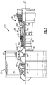
- FIG. 1 schematically illustrates an example turbomachine, which is a gas turbine engine 20 in this example.
- the gas turbine engine 20 is a two-spool turbofan gas turbine engine that generally includes a fan section 22, a compression section 24, a combustion section 26, and a turbine section 28.
- turbofan gas turbine engine Although depicted as a two-spool turbofan gas turbine engine in the disclosed non-limiting embodiment, it should be understood that the concepts described herein are not limited to use with turbofans. That is, the teachings may be applied to other types of turbomachines and turbine engines including three-spool architectures. Further, the concepts described herein could be used in environments other than a turbomachine environment and in applications other than aerospace applications, such as automotive applications.
- flow moves from the fan section 22 to a bypass flowpath.
- Flow from the bypass flowpath generates forward thrust.
- the compression section 24 drives air along the core flowpath. Compressed air from the compression section 24 communicates through the combustion section 26. The products of combustion expand through the turbine section 28.
- the example engine 20 generally includes a low-speed spool 30 and a high-speed spool 32 mounted for rotation about an engine central axis A.
- the low-speed spool 30 and the high-speed spool 32 are rotatably supported by several bearing systems 38. It should be understood that various bearing systems 38 at various locations may alternatively, or additionally, be provided.
- the low-speed spool 30 generally includes a shaft 40 that interconnects a fan 42, a low-pressure compressor 44, and a low-pressure turbine 46.
- the shaft 40 is connected to the fan 42 through a geared architecture 48 to drive the fan 42 at a lower speed than the low-speed spool 30.
- the high-speed spool 32 includes a shaft 50 that interconnects a high-pressure compressor 52 and high-pressure turbine 54.
- the shaft 40 and the shaft 50 are concentric and rotate via bearing systems 38 about the engine central longitudinal axis A, which is collinear with the longitudinal axes of the shaft 40 and the shaft 50.
- the geared architecture 48 of the example engine 20 includes an epicyclic gear train, such as a planetary gear system or other gear system.
- the example epicyclic gear train has a gear reduction ratio of greater than about 2.3 (2.3 to 1).
- the low-pressure turbine 46 pressure ratio is pressure measured prior to inlet of low-pressure turbine 46 as related to the pressure at the outlet of the low-pressure turbine 46 prior to an exhaust nozzle of the engine 20.
- the bypass ratio of the engine 20 is greater than about ten (10 to 1)
- the fan diameter is significantly larger than that of the low pressure compressor 44
- the low-pressure turbine 46 has a pressure ratio that is greater than about 5 (5 to 1).
- the geared architecture 48 of this embodiment is an epicyclic gear train with a gear reduction ratio of greater than about 2.5 (2.5 to 1). It should be understood, however, that the above parameters are only exemplary of one embodiment of a geared architecture engine and that the present disclosure is applicable to other gas turbine engines including direct drive turbofans.
- TSFC Thrust Specific Fuel Consumption
- Fan Pressure Ratio is the pressure ratio across a blade of the fan section 22 without the use of a Fan Exit Guide Vane system.
- the low Fan Pressure Ratio according to one non-limiting embodiment of the example engine 20 is less than 1.45 (1.45 to 1).
- Low Corrected Fan Tip Speed is the actual fan tip speed divided by an industry standard temperature correction of Temperature divided by 518.7 ⁇ 0.5.
- the Temperature represents the ambient temperature in degrees Rankine where (T (°C) - (T (°R) - 491.67) ⁇ 1.8).
- the Low Corrected Fan Tip Speed according to one non-limiting embodiment of the example engine 20 is less than about 1150 fps (351 m/s).
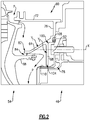
- an example turbomachine seal 60 includes a first leg 64, a second leg 68, a third leg 72, and an attachment portion 76.
- the example seal 60 is a single monolithic structure. That is, the first leg 64, the second leg 68, the third leg 72, and the attachment portion 76 are forged together as a single piece.
- the seal 60 may be a nickel alloy, such as AMS 5663, in some examples.
- the seal 60 is an annular seal that extends circumferentially about the entire axis A.
- the first leg 64, the second leg 68, the third leg 72, and the attachment portion 76 each include at least a portion that extends about the entire axis A.
- the example seal 60 is positioned within the engine 20 within or near a mid-turbine frame that is between the high-pressure turbine 54 and the low-pressure turbine 46.
- the seal 60 is adjacent a bearing compartment 78 of the engine 20.
- the bearing compartment 78 houses some of the bearings 68.
- the attachment portion 76 provides a plurality of apertures 80 that receive fasteners (not shown). The fasteners secure the seal 60 to a portion of the low-pressure turbine 46 (or mid-turbine frame).
- the first leg 64 extends from the attachment portion 76 generally upstream relative to a direction of flow of the engine 20, and radially toward the axis A.
- An end portion 82 of the first leg 64 establishes a radially outer boundary of a channel 84.
- a rotor 88 of the high-pressure turbine 54 establishes a radially inner boundary of the channel 84.
- some flow moves toward the axis A.
- the flow in this example, moves generally along a path P radially past the third leg 72 and then enters the channel 84.
- the flow moves through the channel 84 in a generally axial direction.
- a temperature of the flow near the third leg 72 may be significantly higher than flow that has moved through the channel 84.
- the second leg 68 blocks and redirects flow from the channel 84 from moving directly against the bearing compartment 78.
- the second leg 68 blocks flow from directly contacting a fastener 92 that secures other portions of the bearing compartment 78 within the engine 20. Blocking flow from directly contacting the fastener 92 limits thermal energy movement into the bearing compartment 96 from the flow.
- fasteners may have acted as a conduit that facilitated movement of thermal energy into the bearing compartment.
- the second leg 68 may be considered a wall or barrier in some examples.
- the example second leg 68 extends exclusively in a radial direction from the attachment portion 76 toward the axis A. In other examples, the second leg 68 may be angled relative to an exclusively radial direction.
- the example second leg 68 has a portion 100 that is radially outside the fastener 92 and a portion 104 that is radially inside the fastener 92.
- the second leg 68 is thus considered to extend from a first radial side of the fastener 92 to an opposing, second radial side of the fastener 92.
- the portion 104 effectively seals against a portion of the bearing compartment 78, such as a heat shield 110 associated with the bearing compartment.
- the example second leg 68 extends from the seal 60. In another example, the second leg 68 may extend radially outward from the heat shield 110.
- the fastener 92 extends generally along an axis X.
- the third leg 72 extends in a generally axial direction in this example.
- the third leg 72 may seal against a portion of the high-pressure turbine 54.
- a seal 108 such as a "W" type seal may be used between the seal 60 and the radially outermost portion of the attachment portion 76 to block flow that has moved around the second leg 68.
- leg or wall that acts as a barrier to block a relatively hot flow from directly contacting a bearing compartment fastener. Blocking this flow reduces heating of the bearing compartment due to the flow.
Landscapes
- Engineering & Computer Science (AREA)
- Chemical & Material Sciences (AREA)
- Combustion & Propulsion (AREA)
- Mechanical Engineering (AREA)
- General Engineering & Computer Science (AREA)
- Turbine Rotor Nozzle Sealing (AREA)
- Sealing Using Fluids, Sealing Without Contact, And Removal Of Oil (AREA)
Description
- This disclosure relates generally to a turbomachine seal and, more particularly, to a turbomachine seal that limits thermal energy movement to a bearing compartment.
- Turbomachines, such as gas turbine engines, typically include a fan section, a compression section, a combustion section, and a turbine section. Turbomachines may employ a geared architecture connecting portions of the compression section to the fan section.
- Hot gases move through the turbomachine during operation. High levels of thermal energy are not desirable in some areas of the turbomachine as is known. For example, too much thermal energy in the bearing compartment may undesirably coke lubricant in the bearing compartment.
- A prior art bearing system having the features of the preamble of claim 1 is disclosed in
US 2012/0189429 A1 . A prior art method for assembling a gas turbine engine is disclosed inUS 2004/0168443 A1 . A prior art gas turbine engine assembly is disclosed inUS 3,312,448 A . - According to the present invention, there is provided a turbomachine as claimed in claim 1, and a method as claimed in claim 14.
- In a further nonlimiting embodiment of any of the foregoing seals, the second leg may extend from the attachment portion radially past the attachment.
- In a further nonlimiting embodiment of any of the foregoing seals, the first leg may be configured to provide a channel with a turbine section of the turbomachine. The channel may communicate fluid toward the second leg.
- In a further nonlimiting embodiment of any of the foregoing seals, the first leg may extend axially forward of the second leg.
- In a further nonlimiting embodiment of any of the foregoing seals, a portion of the first leg and the second leg are radially aligned.
- In a further nonlimiting embodiment of any of the foregoing seals, a portion of the first leg and a portion of the second leg are radially aligned with the attachment.
- In a further nonlimiting of any of the foregoing seals, the attachment portion, the first leg, and the second leg are formed as a single monolithic structure.
- In a further nonlimiting embodiment of any of the foregoing seals, a third leg is may be radially outboard of the attachment portion, the third leg may be configured to provide a seal with a turbine section of the turbomachine.
- In a further nonlimiting embodiment of any of the foregoing seals, the attachment portion may provide a plurality of apertures that are each configured to receive a fastener that secures the attachment portion directly to a low-pressure turbine section of the turbomachine.
- In a further nonlimiting embodiment of any of the foregoing seals, the attachment portion, the first leg, and the second leg may each extend circumferentially about an axis of the turbomachine.
- A shield according to another exemplary aspect of the present disclosure includes, among other things, a wall that is spaced axially forward from a portion of a bearing compartment. The wall is configured to redirect an axial flow from a turbine section of a turbomachine. The axial flow moves toward the portion of the bearing compartment through a channel provided at least partially by a turbine rotor.
- In a further nonlimiting embodiment of the foregoing shield, the wall may extend from a first radial side of a bearing compartment fastener to an opposing, second radial side of the bearing compartment fastener.
- In a further nonlimiting embodiment of either of the foregoing shields, a radially innermost end of the wall may be configured to establish a seal with at least a portion of the bearing compartment.
- In a further nonlimiting embodiment of any of the foregoing shields, the wall is a first wall. The turbine rotor may provide a radially inner boundary of the channel, and a second wall may provide a radially outer body of the channel. The second wall may be directly connected to the first wall.
- In a further nonlimiting embodiment of any of the foregoing shields, the first wall may be positioned axially between a high-pressure turbine and a low-pressure turbine of a turbomachine.
- In a further nonlimiting embodiment of any of foregoing shields, the wall extends radially outward from a heat shield of the bearing compartment.
- The various features and advantages of the disclosed examples will become apparent to those skilled in the art from the detailed description. The figures that accompany the detailed description can be briefly described as follows:
-
Figure 1 shows a schematic view of an example turbomachine. -
Figure 2 shows a section view of an annular turbomachine seal within the turbomachine offigure 1 . -
Figure 3 shows a perspective view of theFigure 2 annular turbomachine seal. -
Figure 4 shows a section view at line 4-4 inFigure 3 . -
Figure 1 schematically illustrates an example turbomachine, which is agas turbine engine 20 in this example. Thegas turbine engine 20 is a two-spool turbofan gas turbine engine that generally includes afan section 22, a compression section 24, acombustion section 26, and aturbine section 28. - Although depicted as a two-spool turbofan gas turbine engine in the disclosed non-limiting embodiment, it should be understood that the concepts described herein are not limited to use with turbofans. That is, the teachings may be applied to other types of turbomachines and turbine engines including three-spool architectures. Further, the concepts described herein could be used in environments other than a turbomachine environment and in applications other than aerospace applications, such as automotive applications.
- In the
example engine 20, flow moves from thefan section 22 to a bypass flowpath. Flow from the bypass flowpath generates forward thrust. The compression section 24 drives air along the core flowpath. Compressed air from the compression section 24 communicates through thecombustion section 26. The products of combustion expand through theturbine section 28. - The
example engine 20 generally includes a low-speed spool 30 and a high-speed spool 32 mounted for rotation about an engine central axis A. The low-speed spool 30 and the high-speed spool 32 are rotatably supported byseveral bearing systems 38. It should be understood thatvarious bearing systems 38 at various locations may alternatively, or additionally, be provided. - The low-
speed spool 30 generally includes ashaft 40 that interconnects afan 42, a low-pressure compressor 44, and a low-pressure turbine 46. Theshaft 40 is connected to thefan 42 through a gearedarchitecture 48 to drive thefan 42 at a lower speed than the low-speed spool 30. - The high-
speed spool 32 includes ashaft 50 that interconnects a high-pressure compressor 52 and high-pressure turbine 54. - The
shaft 40 and theshaft 50 are concentric and rotate viabearing systems 38 about the engine central longitudinal axis A, which is collinear with the longitudinal axes of theshaft 40 and theshaft 50. - The
combustion section 26 includes a circumferentially distributed array ofcombustors 56 generally arranged axially between the high-pressure compressor 52 and the high-pressure turbine 54. - In some non-limiting examples, the
engine 20 is a high-bypass geared aircraft engine. In a further example, theengine 20 bypass ratio is greater than about six (6 to 1). - The geared
architecture 48 of theexample engine 20 includes an epicyclic gear train, such as a planetary gear system or other gear system. The example epicyclic gear train has a gear reduction ratio of greater than about 2.3 (2.3 to 1). - The low-
pressure turbine 46 pressure ratio is pressure measured prior to inlet of low-pressure turbine 46 as related to the pressure at the outlet of the low-pressure turbine 46 prior to an exhaust nozzle of theengine 20. In one non-limiting embodiment, the bypass ratio of theengine 20 is greater than about ten (10 to 1), the fan diameter is significantly larger than that of thelow pressure compressor 44, and the low-pressure turbine 46 has a pressure ratio that is greater than about 5 (5 to 1). The gearedarchitecture 48 of this embodiment is an epicyclic gear train with a gear reduction ratio of greater than about 2.5 (2.5 to 1). It should be understood, however, that the above parameters are only exemplary of one embodiment of a geared architecture engine and that the present disclosure is applicable to other gas turbine engines including direct drive turbofans. - In this embodiment of the
example engine 20, a significant amount of thrust is provided by the bypass flow B due to the high bypass ratio. Thefan section 22 of theengine 20 is designed for a particular flight conditiontypically cruise at about 0.8 Mach and about 35,000 feet (10,668 m). This flight condition, with theengine 20 at its best fuel consumption, is also known as "Bucket Cruise" Thrust Specific Fuel Consumption (TSFC). TSFC is an industry standard parameter of fuel consumption per unit of thrust. - Fan Pressure Ratio is the pressure ratio across a blade of the
fan section 22 without the use of a Fan Exit Guide Vane system. The low Fan Pressure Ratio according to one non-limiting embodiment of theexample engine 20 is less than 1.45 (1.45 to 1). - Low Corrected Fan Tip Speed is the actual fan tip speed divided by an industry standard temperature correction of Temperature divided by 518.7 ^ 0.5. The Temperature represents the ambient temperature in degrees Rankine where (T (°C) - (T (°R) - 491.67) ÷ 1.8). The Low Corrected Fan Tip Speed according to one non-limiting embodiment of the
example engine 20 is less than about 1150 fps (351 m/s). - Referring to
Figures 2 to 4 with continuing reference toFigure 1 , anexample turbomachine seal 60 includes afirst leg 64, asecond leg 68, athird leg 72, and anattachment portion 76. Theexample seal 60 is a single monolithic structure. That is, thefirst leg 64, thesecond leg 68, thethird leg 72, and theattachment portion 76 are forged together as a single piece. Theseal 60 may be a nickel alloy, such as AMS 5663, in some examples. - The
seal 60 is an annular seal that extends circumferentially about the entire axis A. In this example, thefirst leg 64, thesecond leg 68, thethird leg 72, and theattachment portion 76 each include at least a portion that extends about the entire axis A. - The
example seal 60 is positioned within theengine 20 within or near a mid-turbine frame that is between the high-pressure turbine 54 and the low-pressure turbine 46. Theseal 60 is adjacent abearing compartment 78 of theengine 20. Thebearing compartment 78 houses some of thebearings 68. Theattachment portion 76 provides a plurality ofapertures 80 that receive fasteners (not shown). The fasteners secure theseal 60 to a portion of the low-pressure turbine 46 (or mid-turbine frame). - The
first leg 64 extends from theattachment portion 76 generally upstream relative to a direction of flow of theengine 20, and radially toward the axis A. Anend portion 82 of thefirst leg 64 establishes a radially outer boundary of achannel 84. Arotor 88 of the high-pressure turbine 54 establishes a radially inner boundary of thechannel 84. - During operation, some flow (from a core flowpath of the engine 20) moves toward the axis A. The flow, in this example, moves generally along a path P radially past the
third leg 72 and then enters thechannel 84. The flow moves through thechannel 84 in a generally axial direction. In this example, a temperature of the flow near thethird leg 72 may be significantly higher than flow that has moved through thechannel 84. - The
second leg 68 blocks and redirects flow from thechannel 84 from moving directly against the bearingcompartment 78. In this example, thesecond leg 68 blocks flow from directly contacting afastener 92 that secures other portions of thebearing compartment 78 within theengine 20. Blocking flow from directly contacting thefastener 92 limits thermal energy movement into the bearing compartment 96 from the flow. In the prior art, such fasteners may have acted as a conduit that facilitated movement of thermal energy into the bearing compartment. - In a specific example, temperatures experienced by the fastener are about 20°F (11°F) (T[°C] = (T[°F] - 32) x 5/9)) lower when used with seal designs having the
second leg 68 than when used with seal designs not having thesecond leg 68. - The
second leg 68 may be considered a wall or barrier in some examples. The examplesecond leg 68 extends exclusively in a radial direction from theattachment portion 76 toward the axis A. In other examples, thesecond leg 68 may be angled relative to an exclusively radial direction. - The example
second leg 68 has aportion 100 that is radially outside thefastener 92 and aportion 104 that is radially inside thefastener 92. Thesecond leg 68 is thus considered to extend from a first radial side of thefastener 92 to an opposing, second radial side of thefastener 92. In some examples, theportion 104 effectively seals against a portion of thebearing compartment 78, such as aheat shield 110 associated with the bearing compartment. - The example
second leg 68 extends from theseal 60. In another example, thesecond leg 68 may extend radially outward from theheat shield 110. - The
fastener 92 extends generally along an axis X. Thefirst leg 64 andsecond leg 68, in this example, each include portions (Y1 and Y2, respectively) that are radially aligned with the faster 92. - The
third leg 72 extends in a generally axial direction in this example. Thethird leg 72 may seal against a portion of the high-pressure turbine 54. - A
seal 108, such as a "W" type seal may be used between theseal 60 and the radially outermost portion of theattachment portion 76 to block flow that has moved around thesecond leg 68. - Features of the disclosed examples include a leg or wall that acts as a barrier to block a relatively hot flow from directly contacting a bearing compartment fastener. Blocking this flow reduces heating of the bearing compartment due to the flow.
- The preceding description is exemplary rather than limiting in nature. Variations and modifications to the disclosed examples may become apparent to those skilled in the art that do not necessarily depart from the essence of this disclosure. Thus, the scope of legal protection given to this disclosure can only be determined by studying the following claims.
Claims (15)
- A turbomachine comprising an annular seal, the annular seal (60), comprising:an attachment portion (76); anda first leg (64) radially inward of the attachment portion (76), characterised by:
a second leg (68) being radially inward of the attachment portion (76) and configured to block flow from directly contacting a fastener (92) associated with a bearing compartment (78; 96) of the turbomachine, wherein the second leg (68) is spaced axially forward from at least a portion of the bearing compartment (78; 96) and is configured to redirect an axial flow from a turbine section (28) of the turbomachine, the axial flow moving toward the portion of the bearing compartment (78; 96) through a channel (84) provided at least partially by a turbine rotor (88). - The turbomachine of claim 1, wherein the second leg (68) is configured to seal against the bearing compartment (78; 96).
- The turbomachine of claim 1 or 2, wherein the second leg (68) extends exclusively in a radial direction.
- The turbomachine of any preceding claim, wherein the second leg (68) extends from the attachment portion (76) radially past the fastener (92).
- The turbomachine of any preceding claim, wherein the first leg (64) extends axially forward of the second leg (68).
- The turbomachine of any preceding claim, wherein at least a portion of the first leg (64) and the second leg (68) are radially aligned.
- The turbomachine of any preceding claim, wherein at least a portion of the first leg (64) and at least a portion of the second leg (68) are radially aligned with the fastener (92).
- The turbomachine of any preceding claim, wherein the attachment portion (76), the first leg (64), and the second leg (68) are formed as a single monolithic structure.
- The turbomachine of any preceding claim, including a third leg (72) radially outward of the attachment portion (76), the third leg (72) configured to provide a seal (60) with a turbine section (28) of the turbomachine.
- The turbomachine of any preceding claim, wherein:the attachment portion (76) provides a plurality of apertures (80) each configured to receive a fastener (92) that secures the attachment portion (76) directly to a low pressure turbine section (46) of the turbomachine; and/orthe attachment portion (76), the first leg (64), and the second leg (68) each extend circumferentially about an axis (A) of the turbomachine.
- The turbomachine of any preceding claim, wherein the second leg (68) extends from a first radial side of the fastener (92) to an opposing, second radial side of the fastener (92).
- The turbomachine of any preceding claim, wherein a radially innermost end of the second leg (78) is configured to establish a seal (60) with at least the portion of the bearing compartment (78; 96).
- The turbomachine of any preceding claim, wherein the second leg (78):is positioned axially between a high-pressure turbine (54) and a low-pressure turbine (46) of the turbomachine; and/orextends radially outward from a heat shield (110) of the bearing compartment (78; 92).
- A method of limiting thermal energy movement to a bearing compartment (78; 96), comprising:moving flow through a channel (84) provided by a first leg (68) of an annual seal (60) and a turbine rotor (88); andredirecting flow from the channel (84) away from a bearing compartment (78; 96) using a second leg (68) of the annual seal (60) that is axially spaced from the channel (84).
- The method of claim 14, including sealing against the bearing compartment (78; 96) with the second leg (68).
Applications Claiming Priority (2)
| Application Number | Priority Date | Filing Date | Title |
|---|---|---|---|
| US13/590,348 US9328626B2 (en) | 2012-08-21 | 2012-08-21 | Annular turbomachine seal and heat shield |
| PCT/US2013/055489 WO2014031502A1 (en) | 2012-08-21 | 2013-08-18 | Annular turbomachine seal and heat shield |
Publications (3)
| Publication Number | Publication Date |
|---|---|
| EP2888463A1 EP2888463A1 (en) | 2015-07-01 |
| EP2888463A4 EP2888463A4 (en) | 2015-09-16 |
| EP2888463B1 true EP2888463B1 (en) | 2018-10-10 |
Family
ID=50148113
Family Applications (1)
| Application Number | Title | Priority Date | Filing Date |
|---|---|---|---|
| EP13831730.0A Active EP2888463B1 (en) | 2012-08-21 | 2013-08-18 | Annular turbomachine seal and heat shield |
Country Status (3)
| Country | Link |
|---|---|
| US (1) | US9328626B2 (en) |
| EP (1) | EP2888463B1 (en) |
| WO (1) | WO2014031502A1 (en) |
Families Citing this family (10)
| Publication number | Priority date | Publication date | Assignee | Title |
|---|---|---|---|---|
| EP2508713A1 (en) * | 2011-04-04 | 2012-10-10 | Siemens Aktiengesellschaft | Gas turbine comprising a heat shield and method of operation |
| DE102013007443A1 (en) * | 2013-04-30 | 2014-10-30 | Rolls-Royce Deutschland Ltd & Co Kg | Burner seal for gas turbine combustor head and heat shield |
| US10161256B2 (en) * | 2015-01-22 | 2018-12-25 | Untied Technologies Corporation | Seal with backup seal |
| US9926797B2 (en) | 2015-01-22 | 2018-03-27 | United Technologies Corporation | Flange trapped seal configuration |
| US10215098B2 (en) | 2015-01-22 | 2019-02-26 | United Technologies Corporation | Bearing compartment seal |
| US10107141B2 (en) * | 2015-04-13 | 2018-10-23 | United Technologies Corporation | Seal configurations for turbine assembly and bearing compartment interfaces |
| US10247106B2 (en) * | 2016-06-15 | 2019-04-02 | General Electric Company | Method and system for rotating air seal with integral flexible heat shield |
| US10513938B2 (en) | 2017-04-25 | 2019-12-24 | United Technologies Corporation | Intershaft compartment buffering arrangement |
| US20180347399A1 (en) * | 2017-06-01 | 2018-12-06 | Pratt & Whitney Canada Corp. | Turbine shroud with integrated heat shield |
| DE102018132723A1 (en) * | 2018-12-18 | 2020-06-18 | Karlsruher Institut für Technologie | Deflector to prevent oil from escaping |
Family Cites Families (27)
| Publication number | Priority date | Publication date | Assignee | Title |
|---|---|---|---|---|
| US2930662A (en) | 1956-11-01 | 1960-03-29 | Bristol Aero Engines Ltd | Supporting structure for a gas turbine bearing |
| US3312448A (en) | 1965-03-01 | 1967-04-04 | Gen Electric | Seal arrangement for preventing leakage of lubricant in gas turbine engines |
| US4709545A (en) | 1983-05-31 | 1987-12-01 | United Technologies Corporation | Bearing compartment protection system |
| DE3638961A1 (en) | 1986-11-14 | 1988-05-26 | Mtu Muenchen Gmbh | GAS TURBINE ENGINE WITH A HIGH PRESSURE COMPRESSOR |
| US4987736A (en) | 1988-12-14 | 1991-01-29 | General Electric Company | Lightweight gas turbine engine frame with free-floating heat shield |
| US5284347A (en) * | 1991-03-25 | 1994-02-08 | General Electric Company | Gas bearing sealing means |
| US5226788A (en) | 1991-12-23 | 1993-07-13 | General Electric Company | Turbine heat shield and bolt retainer assembly |
| US5211541A (en) | 1991-12-23 | 1993-05-18 | General Electric Company | Turbine support assembly including turbine heat shield and bolt retainer assembly |
| US5180279A (en) | 1992-03-31 | 1993-01-19 | General Motors Corporation | Heat shield and deflector for engine cooling fan motor |
| JP3555683B2 (en) | 1992-08-11 | 2004-08-18 | ユナイテッド・テクノロジーズ・コーポレイション | Seal assembly for rotating machine |
| US5252026A (en) | 1993-01-12 | 1993-10-12 | General Electric Company | Gas turbine engine nozzle |
| US5399066A (en) | 1993-09-30 | 1995-03-21 | General Electric Company | Integral clearance control impingement manifold and environmental shield |
| US5656353A (en) | 1995-06-27 | 1997-08-12 | Tba Composites, Inc. | Laminated heat shield with prongs and method of manufacturing same |
| US5622438A (en) | 1995-07-12 | 1997-04-22 | United Technologies Corporation | Fire resistant bearing compartment cover |
| US6196790B1 (en) | 1998-12-17 | 2001-03-06 | United Technologies Corporation | Seal assembly for an intershaft seal in a gas turbine engine |
| US6676369B2 (en) * | 2002-03-26 | 2004-01-13 | General Electric Company | Aspirating face seal with axially extending seal teeth |
| US6935837B2 (en) | 2003-02-27 | 2005-08-30 | General Electric Company | Methods and apparatus for assembling gas turbine engines |
| FR2858649B1 (en) * | 2003-08-05 | 2005-09-23 | Snecma Moteurs | TURBOMACHINE LOW PRESSURE TURBINE |
| US6887038B2 (en) * | 2003-09-02 | 2005-05-03 | General Electric Company | Methods and apparatus to facilitate sealing between rotating turbine shafts |
| US7287384B2 (en) | 2004-12-13 | 2007-10-30 | Pratt & Whitney Canada Corp. | Bearing chamber pressurization system |
| DE102005007776A1 (en) * | 2005-02-19 | 2006-08-31 | Mtu Aero Engines Gmbh | bearing arrangement |
| DE502005006421D1 (en) | 2005-04-14 | 2009-02-26 | Rolls Royce Deutschland | Arrangement for internal passive clearance adjustment in a high-pressure turbine |
| US7410341B2 (en) | 2005-06-22 | 2008-08-12 | Honeywell International, Inc. | Internally-cooled seal housing for turbine engine |
| US7909570B2 (en) * | 2006-08-25 | 2011-03-22 | Pratt & Whitney Canada Corp. | Interturbine duct with integrated baffle and seal |
| US8662845B2 (en) | 2011-01-11 | 2014-03-04 | United Technologies Corporation | Multi-function heat shield for a gas turbine engine |
| US8747054B2 (en) | 2011-01-24 | 2014-06-10 | United Technologies Corporation | Bearing system for gas turbine engine |
| US8979483B2 (en) * | 2011-11-07 | 2015-03-17 | United Technologies Corporation | Mid-turbine bearing support |
-
2012
- 2012-08-21 US US13/590,348 patent/US9328626B2/en active Active
-
2013
- 2013-08-18 EP EP13831730.0A patent/EP2888463B1/en active Active
- 2013-08-18 WO PCT/US2013/055489 patent/WO2014031502A1/en not_active Ceased
Non-Patent Citations (1)
| Title |
|---|
| None * |
Also Published As
| Publication number | Publication date |
|---|---|
| EP2888463A1 (en) | 2015-07-01 |
| US9328626B2 (en) | 2016-05-03 |
| US20140056685A1 (en) | 2014-02-27 |
| WO2014031502A1 (en) | 2014-02-27 |
| EP2888463A4 (en) | 2015-09-16 |
Similar Documents
| Publication | Publication Date | Title |
|---|---|---|
| US9328626B2 (en) | Annular turbomachine seal and heat shield | |
| EP2809891B1 (en) | Gas turbine engine mid turbine frame bearing support | |
| US9255487B2 (en) | Gas turbine engine seal carrier | |
| EP2900937B1 (en) | Turbomachine bearing support structure | |
| EP2971611B1 (en) | Turbine engine with multi-layered case flange | |
| EP3095964B1 (en) | Pre-skewed capture plate | |
| EP3060782B1 (en) | Face seal assembly with retaining plate | |
| EP2927433B1 (en) | Active clearance control for gas turbine engine | |
| EP2900999B1 (en) | Seal damper with improved retention | |
| EP3093445B1 (en) | Gas turbine vane and method of forming | |
| EP2984291B1 (en) | Nozzle segment for a gas turbine engine | |
| EP3296519B1 (en) | Flowpath component for a gas turbine engine including a chordal seal | |
| EP3094823B1 (en) | Gas turbine engine component and corresponding gas turbine engine | |
| EP2917508B1 (en) | Gas turbine engine with a compressor bleed air slot | |
| EP2971683B1 (en) | Gas turbine engine heat exchanger manifold | |
| EP3708773B1 (en) | Gas turbine engine comprising a seal for a rotor stack and corresponding method of sealing a shaft relatively to a rotor disk | |
| EP2900978B1 (en) | Compressor section comprising a seal hook mount structure with overlapped coating | |
| EP3450685B1 (en) | Gas turbine engine component | |
| EP3068981B1 (en) | Flange relief for split casing | |
| EP3101236B1 (en) | Trailing edge platform seals | |
| EP3012411B1 (en) | Integrally bladed rotor having axial arm and pocket | |
| EP2998514B1 (en) | Reversibly mountable blade platform seal | |
| EP3597870B1 (en) | Gas turbine engine | |
| EP3073060B1 (en) | Seal support structures for turbomachines | |
| EP3109403B1 (en) | Reversible blade rotor seal with protrusions |
Legal Events
| Date | Code | Title | Description |
|---|---|---|---|
| PUAI | Public reference made under article 153(3) epc to a published international application that has entered the european phase |
Free format text: ORIGINAL CODE: 0009012 |
|
| 17P | Request for examination filed |
Effective date: 20150323 |
|
| AK | Designated contracting states |
Kind code of ref document: A1 Designated state(s): AL AT BE BG CH CY CZ DE DK EE ES FI FR GB GR HR HU IE IS IT LI LT LU LV MC MK MT NL NO PL PT RO RS SE SI SK SM TR |
|
| AX | Request for extension of the european patent |
Extension state: BA ME |
|
| RA4 | Supplementary search report drawn up and despatched (corrected) |
Effective date: 20150814 |
|
| RIC1 | Information provided on ipc code assigned before grant |
Ipc: F01D 11/02 20060101ALI20150810BHEP Ipc: F02C 7/00 20060101ALI20150810BHEP Ipc: F02C 7/24 20060101ALI20150810BHEP Ipc: F02C 7/28 20060101AFI20150810BHEP |
|
| DAX | Request for extension of the european patent (deleted) | ||
| RAP1 | Party data changed (applicant data changed or rights of an application transferred) |
Owner name: UNITED TECHNOLOGIES CORPORATION |
|
| STAA | Information on the status of an ep patent application or granted ep patent |
Free format text: STATUS: EXAMINATION IS IN PROGRESS |
|
| 17Q | First examination report despatched |
Effective date: 20161207 |
|
| GRAP | Despatch of communication of intention to grant a patent |
Free format text: ORIGINAL CODE: EPIDOSNIGR1 |
|
| STAA | Information on the status of an ep patent application or granted ep patent |
Free format text: STATUS: GRANT OF PATENT IS INTENDED |
|
| INTG | Intention to grant announced |
Effective date: 20180404 |
|
| GRAS | Grant fee paid |
Free format text: ORIGINAL CODE: EPIDOSNIGR3 |
|
| GRAJ | Information related to disapproval of communication of intention to grant by the applicant or resumption of examination proceedings by the epo deleted |
Free format text: ORIGINAL CODE: EPIDOSDIGR1 |
|
| GRAL | Information related to payment of fee for publishing/printing deleted |
Free format text: ORIGINAL CODE: EPIDOSDIGR3 |
|
| STAA | Information on the status of an ep patent application or granted ep patent |
Free format text: STATUS: EXAMINATION IS IN PROGRESS |
|
| GRAR | Information related to intention to grant a patent recorded |
Free format text: ORIGINAL CODE: EPIDOSNIGR71 |
|
| STAA | Information on the status of an ep patent application or granted ep patent |
Free format text: STATUS: GRANT OF PATENT IS INTENDED |
|
| GRAA | (expected) grant |
Free format text: ORIGINAL CODE: 0009210 |
|
| STAA | Information on the status of an ep patent application or granted ep patent |
Free format text: STATUS: THE PATENT HAS BEEN GRANTED |
|
| INTC | Intention to grant announced (deleted) | ||
| AK | Designated contracting states |
Kind code of ref document: B1 Designated state(s): AL AT BE BG CH CY CZ DE DK EE ES FI FR GB GR HR HU IE IS IT LI LT LU LV MC MK MT NL NO PL PT RO RS SE SI SK SM TR |
|
| INTG | Intention to grant announced |
Effective date: 20180904 |
|
| REG | Reference to a national code |
Ref country code: GB Ref legal event code: FG4D |
|
| REG | Reference to a national code |
Ref country code: CH Ref legal event code: EP Ref country code: AT Ref legal event code: REF Ref document number: 1051514 Country of ref document: AT Kind code of ref document: T Effective date: 20181015 |
|
| REG | Reference to a national code |
Ref country code: IE Ref legal event code: FG4D |
|
| REG | Reference to a national code |
Ref country code: DE Ref legal event code: R096 Ref document number: 602013044992 Country of ref document: DE |
|
| REG | Reference to a national code |
Ref country code: NL Ref legal event code: MP Effective date: 20181010 |
|
| REG | Reference to a national code |
Ref country code: LT Ref legal event code: MG4D |
|
| REG | Reference to a national code |
Ref country code: AT Ref legal event code: MK05 Ref document number: 1051514 Country of ref document: AT Kind code of ref document: T Effective date: 20181010 |
|
| PG25 | Lapsed in a contracting state [announced via postgrant information from national office to epo] |
Ref country code: NL Free format text: LAPSE BECAUSE OF FAILURE TO SUBMIT A TRANSLATION OF THE DESCRIPTION OR TO PAY THE FEE WITHIN THE PRESCRIBED TIME-LIMIT Effective date: 20181010 |
|
| PG25 | Lapsed in a contracting state [announced via postgrant information from national office to epo] |
Ref country code: FI Free format text: LAPSE BECAUSE OF FAILURE TO SUBMIT A TRANSLATION OF THE DESCRIPTION OR TO PAY THE FEE WITHIN THE PRESCRIBED TIME-LIMIT Effective date: 20181010 Ref country code: LV Free format text: LAPSE BECAUSE OF FAILURE TO SUBMIT A TRANSLATION OF THE DESCRIPTION OR TO PAY THE FEE WITHIN THE PRESCRIBED TIME-LIMIT Effective date: 20181010 Ref country code: HR Free format text: LAPSE BECAUSE OF FAILURE TO SUBMIT A TRANSLATION OF THE DESCRIPTION OR TO PAY THE FEE WITHIN THE PRESCRIBED TIME-LIMIT Effective date: 20181010 Ref country code: PL Free format text: LAPSE BECAUSE OF FAILURE TO SUBMIT A TRANSLATION OF THE DESCRIPTION OR TO PAY THE FEE WITHIN THE PRESCRIBED TIME-LIMIT Effective date: 20181010 Ref country code: AT Free format text: LAPSE BECAUSE OF FAILURE TO SUBMIT A TRANSLATION OF THE DESCRIPTION OR TO PAY THE FEE WITHIN THE PRESCRIBED TIME-LIMIT Effective date: 20181010 Ref country code: BG Free format text: LAPSE BECAUSE OF FAILURE TO SUBMIT A TRANSLATION OF THE DESCRIPTION OR TO PAY THE FEE WITHIN THE PRESCRIBED TIME-LIMIT Effective date: 20190110 Ref country code: NO Free format text: LAPSE BECAUSE OF FAILURE TO SUBMIT A TRANSLATION OF THE DESCRIPTION OR TO PAY THE FEE WITHIN THE PRESCRIBED TIME-LIMIT Effective date: 20190110 Ref country code: LT Free format text: LAPSE BECAUSE OF FAILURE TO SUBMIT A TRANSLATION OF THE DESCRIPTION OR TO PAY THE FEE WITHIN THE PRESCRIBED TIME-LIMIT Effective date: 20181010 Ref country code: IS Free format text: LAPSE BECAUSE OF FAILURE TO SUBMIT A TRANSLATION OF THE DESCRIPTION OR TO PAY THE FEE WITHIN THE PRESCRIBED TIME-LIMIT Effective date: 20190210 Ref country code: ES Free format text: LAPSE BECAUSE OF FAILURE TO SUBMIT A TRANSLATION OF THE DESCRIPTION OR TO PAY THE FEE WITHIN THE PRESCRIBED TIME-LIMIT Effective date: 20181010 |
|
| PG25 | Lapsed in a contracting state [announced via postgrant information from national office to epo] |
Ref country code: PT Free format text: LAPSE BECAUSE OF FAILURE TO SUBMIT A TRANSLATION OF THE DESCRIPTION OR TO PAY THE FEE WITHIN THE PRESCRIBED TIME-LIMIT Effective date: 20190210 Ref country code: GR Free format text: LAPSE BECAUSE OF FAILURE TO SUBMIT A TRANSLATION OF THE DESCRIPTION OR TO PAY THE FEE WITHIN THE PRESCRIBED TIME-LIMIT Effective date: 20190111 Ref country code: SE Free format text: LAPSE BECAUSE OF FAILURE TO SUBMIT A TRANSLATION OF THE DESCRIPTION OR TO PAY THE FEE WITHIN THE PRESCRIBED TIME-LIMIT Effective date: 20181010 Ref country code: RS Free format text: LAPSE BECAUSE OF FAILURE TO SUBMIT A TRANSLATION OF THE DESCRIPTION OR TO PAY THE FEE WITHIN THE PRESCRIBED TIME-LIMIT Effective date: 20181010 Ref country code: AL Free format text: LAPSE BECAUSE OF FAILURE TO SUBMIT A TRANSLATION OF THE DESCRIPTION OR TO PAY THE FEE WITHIN THE PRESCRIBED TIME-LIMIT Effective date: 20181010 |
|
| REG | Reference to a national code |
Ref country code: DE Ref legal event code: R097 Ref document number: 602013044992 Country of ref document: DE |
|
| PG25 | Lapsed in a contracting state [announced via postgrant information from national office to epo] |
Ref country code: IT Free format text: LAPSE BECAUSE OF FAILURE TO SUBMIT A TRANSLATION OF THE DESCRIPTION OR TO PAY THE FEE WITHIN THE PRESCRIBED TIME-LIMIT Effective date: 20181010 Ref country code: CZ Free format text: LAPSE BECAUSE OF FAILURE TO SUBMIT A TRANSLATION OF THE DESCRIPTION OR TO PAY THE FEE WITHIN THE PRESCRIBED TIME-LIMIT Effective date: 20181010 Ref country code: DK Free format text: LAPSE BECAUSE OF FAILURE TO SUBMIT A TRANSLATION OF THE DESCRIPTION OR TO PAY THE FEE WITHIN THE PRESCRIBED TIME-LIMIT Effective date: 20181010 |
|
| PLBE | No opposition filed within time limit |
Free format text: ORIGINAL CODE: 0009261 |
|
| STAA | Information on the status of an ep patent application or granted ep patent |
Free format text: STATUS: NO OPPOSITION FILED WITHIN TIME LIMIT |
|
| PG25 | Lapsed in a contracting state [announced via postgrant information from national office to epo] |
Ref country code: SM Free format text: LAPSE BECAUSE OF FAILURE TO SUBMIT A TRANSLATION OF THE DESCRIPTION OR TO PAY THE FEE WITHIN THE PRESCRIBED TIME-LIMIT Effective date: 20181010 Ref country code: EE Free format text: LAPSE BECAUSE OF FAILURE TO SUBMIT A TRANSLATION OF THE DESCRIPTION OR TO PAY THE FEE WITHIN THE PRESCRIBED TIME-LIMIT Effective date: 20181010 Ref country code: SK Free format text: LAPSE BECAUSE OF FAILURE TO SUBMIT A TRANSLATION OF THE DESCRIPTION OR TO PAY THE FEE WITHIN THE PRESCRIBED TIME-LIMIT Effective date: 20181010 Ref country code: RO Free format text: LAPSE BECAUSE OF FAILURE TO SUBMIT A TRANSLATION OF THE DESCRIPTION OR TO PAY THE FEE WITHIN THE PRESCRIBED TIME-LIMIT Effective date: 20181010 |
|
| 26N | No opposition filed |
Effective date: 20190711 |
|
| PG25 | Lapsed in a contracting state [announced via postgrant information from national office to epo] |
Ref country code: SI Free format text: LAPSE BECAUSE OF FAILURE TO SUBMIT A TRANSLATION OF THE DESCRIPTION OR TO PAY THE FEE WITHIN THE PRESCRIBED TIME-LIMIT Effective date: 20181010 |
|
| PG25 | Lapsed in a contracting state [announced via postgrant information from national office to epo] |
Ref country code: TR Free format text: LAPSE BECAUSE OF FAILURE TO SUBMIT A TRANSLATION OF THE DESCRIPTION OR TO PAY THE FEE WITHIN THE PRESCRIBED TIME-LIMIT Effective date: 20181010 |
|
| PG25 | Lapsed in a contracting state [announced via postgrant information from national office to epo] |
Ref country code: LI Free format text: LAPSE BECAUSE OF NON-PAYMENT OF DUE FEES Effective date: 20190831 Ref country code: MC Free format text: LAPSE BECAUSE OF FAILURE TO SUBMIT A TRANSLATION OF THE DESCRIPTION OR TO PAY THE FEE WITHIN THE PRESCRIBED TIME-LIMIT Effective date: 20181010 Ref country code: LU Free format text: LAPSE BECAUSE OF NON-PAYMENT OF DUE FEES Effective date: 20190818 Ref country code: CH Free format text: LAPSE BECAUSE OF NON-PAYMENT OF DUE FEES Effective date: 20190831 |
|
| REG | Reference to a national code |
Ref country code: BE Ref legal event code: MM Effective date: 20190831 |
|
| PG25 | Lapsed in a contracting state [announced via postgrant information from national office to epo] |
Ref country code: IE Free format text: LAPSE BECAUSE OF NON-PAYMENT OF DUE FEES Effective date: 20190818 |
|
| PG25 | Lapsed in a contracting state [announced via postgrant information from national office to epo] |
Ref country code: BE Free format text: LAPSE BECAUSE OF NON-PAYMENT OF DUE FEES Effective date: 20190831 |
|
| PG25 | Lapsed in a contracting state [announced via postgrant information from national office to epo] |
Ref country code: CY Free format text: LAPSE BECAUSE OF FAILURE TO SUBMIT A TRANSLATION OF THE DESCRIPTION OR TO PAY THE FEE WITHIN THE PRESCRIBED TIME-LIMIT Effective date: 20181010 |
|
| PG25 | Lapsed in a contracting state [announced via postgrant information from national office to epo] |
Ref country code: HU Free format text: LAPSE BECAUSE OF FAILURE TO SUBMIT A TRANSLATION OF THE DESCRIPTION OR TO PAY THE FEE WITHIN THE PRESCRIBED TIME-LIMIT; INVALID AB INITIO Effective date: 20130818 Ref country code: MT Free format text: LAPSE BECAUSE OF FAILURE TO SUBMIT A TRANSLATION OF THE DESCRIPTION OR TO PAY THE FEE WITHIN THE PRESCRIBED TIME-LIMIT Effective date: 20181010 |
|
| PG25 | Lapsed in a contracting state [announced via postgrant information from national office to epo] |
Ref country code: MK Free format text: LAPSE BECAUSE OF FAILURE TO SUBMIT A TRANSLATION OF THE DESCRIPTION OR TO PAY THE FEE WITHIN THE PRESCRIBED TIME-LIMIT Effective date: 20181010 |
|
| REG | Reference to a national code |
Ref country code: DE Ref legal event code: R081 Ref document number: 602013044992 Country of ref document: DE Owner name: RAYTHEON TECHNOLOGIES CORPORATION (N.D.GES.D.S, US Free format text: FORMER OWNER: UNITED TECHNOLOGIES CORPORATION, FARMINGTON, CONN., US Ref country code: DE Ref legal event code: R081 Ref document number: 602013044992 Country of ref document: DE Owner name: RTX CORPORATION (N.D.GES.D. STAATES DELAWARE),, US Free format text: FORMER OWNER: UNITED TECHNOLOGIES CORPORATION, FARMINGTON, CONN., US |
|
| P01 | Opt-out of the competence of the unified patent court (upc) registered |
Effective date: 20230520 |
|
| PGFP | Annual fee paid to national office [announced via postgrant information from national office to epo] |
Ref country code: DE Payment date: 20250724 Year of fee payment: 13 |
|
| PGFP | Annual fee paid to national office [announced via postgrant information from national office to epo] |
Ref country code: GB Payment date: 20250725 Year of fee payment: 13 |
|
| PGFP | Annual fee paid to national office [announced via postgrant information from national office to epo] |
Ref country code: FR Payment date: 20250725 Year of fee payment: 13 |
|
| REG | Reference to a national code |
Ref country code: DE Ref legal event code: R081 Ref document number: 602013044992 Country of ref document: DE Owner name: RTX CORPORATION (N.D.GES.D. STAATES DELAWARE),, US Free format text: FORMER OWNER: RAYTHEON TECHNOLOGIES CORPORATION (N.D.GES.D.STAATES DELAWARE), ARLINGTON, VA, US |