EP2888384B1 - Gamma titanium dual property heat treat system and method - Google Patents
Gamma titanium dual property heat treat system and method Download PDFInfo
- Publication number
- EP2888384B1 EP2888384B1 EP13831687.2A EP13831687A EP2888384B1 EP 2888384 B1 EP2888384 B1 EP 2888384B1 EP 13831687 A EP13831687 A EP 13831687A EP 2888384 B1 EP2888384 B1 EP 2888384B1
- Authority
- EP
- European Patent Office
- Prior art keywords
- blank
- cooling
- forming
- fans
- dual property
- Prior art date
- Legal status (The legal status is an assumption and is not a legal conclusion. Google has not performed a legal analysis and makes no representation as to the accuracy of the status listed.)
- Active
Links
Images



Classifications
-
- C—CHEMISTRY; METALLURGY
- C22—METALLURGY; FERROUS OR NON-FERROUS ALLOYS; TREATMENT OF ALLOYS OR NON-FERROUS METALS
- C22F—CHANGING THE PHYSICAL STRUCTURE OF NON-FERROUS METALS AND NON-FERROUS ALLOYS
- C22F1/00—Changing the physical structure of non-ferrous metals or alloys by heat treatment or by hot or cold working
- C22F1/16—Changing the physical structure of non-ferrous metals or alloys by heat treatment or by hot or cold working of other metals or alloys based thereon
- C22F1/18—High-melting or refractory metals or alloys based thereon
- C22F1/183—High-melting or refractory metals or alloys based thereon of titanium or alloys based thereon
-
- C—CHEMISTRY; METALLURGY
- C22—METALLURGY; FERROUS OR NON-FERROUS ALLOYS; TREATMENT OF ALLOYS OR NON-FERROUS METALS
- C22C—ALLOYS
- C22C14/00—Alloys based on titanium
-
- C—CHEMISTRY; METALLURGY
- C22—METALLURGY; FERROUS OR NON-FERROUS ALLOYS; TREATMENT OF ALLOYS OR NON-FERROUS METALS
- C22C—ALLOYS
- C22C21/00—Alloys based on aluminium
-
- C—CHEMISTRY; METALLURGY
- C21—METALLURGY OF IRON
- C21D—MODIFYING THE PHYSICAL STRUCTURE OF FERROUS METALS; GENERAL DEVICES FOR HEAT TREATMENT OF FERROUS OR NON-FERROUS METALS OR ALLOYS; MAKING METAL MALLEABLE, e.g. BY DECARBURISATION OR TEMPERING
- C21D1/00—General methods or devices for heat treatment, e.g. annealing, hardening, quenching or tempering
- C21D1/62—Quenching devices
-
- C—CHEMISTRY; METALLURGY
- C21—METALLURGY OF IRON
- C21D—MODIFYING THE PHYSICAL STRUCTURE OF FERROUS METALS; GENERAL DEVICES FOR HEAT TREATMENT OF FERROUS OR NON-FERROUS METALS OR ALLOYS; MAKING METAL MALLEABLE, e.g. BY DECARBURISATION OR TEMPERING
- C21D2221/00—Treating localised areas of an article
-
- C—CHEMISTRY; METALLURGY
- C22—METALLURGY; FERROUS OR NON-FERROUS ALLOYS; TREATMENT OF ALLOYS OR NON-FERROUS METALS
- C22F—CHANGING THE PHYSICAL STRUCTURE OF NON-FERROUS METALS AND NON-FERROUS ALLOYS
- C22F1/00—Changing the physical structure of non-ferrous metals or alloys by heat treatment or by hot or cold working
- C22F1/16—Changing the physical structure of non-ferrous metals or alloys by heat treatment or by hot or cold working of other metals or alloys based thereon
- C22F1/18—High-melting or refractory metals or alloys based thereon
Definitions
- the present disclosure relates to a system and a method for forming a part having a dual property microstructure.
- Dual material properties can be achieved on the same piece of material by performing multiple heat treat cycles on a piece of material. This can be accomplished either in ovens with parts being cooled or insulated in certain areas, or by using induction heating to heat different areas of the part at different temperatures at the same time to achieve dual property microstructure. Costs to process, equipment expense, and thermal repeatability are all concerns. Having induction generators and the operators to process the material often limits the locations that these processes can take place. This can result in higher cost to process.
- the present invention provides a method of forming a blank having a dual property microstructure as recited in claim 1.
- the method further comprises forming the cooled blank into a part.
- the blank forming step comprises forming a blank having a triangular shape with the narrow top portion and the wide base portion.
- the blank forming step further comprises forming a bottom which is flat so that the blank can be stood up.
- the heating step comprises heating the blank in a furnace.
- each of said cooling fans may be placed a distance from 1.0 to 3.0 feet from each side of said grate.
- the cooling step further comprises cooling the first portion at a cooling rate in the range of 5.0 to 6.0 deg. F/sec (2.78 to 3.33 deg C/sec). and cooling the second portion at a cooling rate in the range of 3.5 to 4.0 deg. F/sec (1.94 to 2.22 deg C/sec).
- the cooling step further comprises aiming a plurality of the cooling fans at a first portion of the blank and blowing air over the first portion so that the first portion cools at a first cooling rate and allowing a second portion of the blank to cool at a second cooling rate different from the first cooling rate.
- the invention also provides a system for forming a port having a dual microstructure as recited in claim 9.
- the blank has a triangular shape with a narrow top portion, a wide base portion and a flat bottom.
- the blank is formed from titanium aluminide.
- the cooling fans are aimed at a first portion of the blank so that the first portion cools at a cooling rate different from the cooling rate of a second portion of the blank.
- the cooling fans are spaced a distance in the range of from 1.0 to 3.0 feet from each side of the blank.
- a blade blank 10 is shown.
- the blade blank may be formed from a titanium alloy such as Gamma TiAl.
- One suitable alloy is TNM alloy (Ti - 43.5A1 - 4.0Nb - 1.0Mo - 0.1B, all in at%).
- the blade blank 10 may be cut for solution heat treatment in a preform geometry that is wide at the base 12 where a root attachment may be located, and thin at the top 14, where an airfoil tip may be located.
- the blade blank 10 has a triangular shape that is cut flat on the bottom 16. This allows the blade blank 10 to be stood upright with the base 12 on the bottom and the tip 18 facing upward.
- the blade blank 10 is subjected to a heat treatment.
- a heat treatment uses a temperature in the range of from 2240 deg F to 2320 deg F (1226.67 deg C to 1271.11 deg C) for a time period of one hour.
- the heat treatment may be performed in any suitable furnace such as an air furnace.
- the blade blank 10 when formed from a titanium alloy, will be removed from the furnace at a temperature of approximately 2300 degrees F (1260 degrees C).
- the blade blank 10 thus formed is then placed onto a grate 20 as shown in Fig. 3 .
- the grate 20 may have a grid construction formed by a plurality of intersecting bars 22 and 24 as shown in Figure 4 .
- the grate 24 may be formed from any suitable metallic material such as a nickel alloy sold under the name HAYNES 230.
- the grid construction may be such that there are a plurality of openings 26 in the grate.
- the cooling fans 28 and 30 may be positioned and angled so as to blow cooling air on different portions of the blade blank 10 in order to cause the different portions to cool at different rates and thus create different microstructures.
- the cooling fan 28 could be aimed to blow cooling air at the top part 14 of the blank and the cooling fan 30 may be aimed to blow cooling air at the base 12 of the blade blank.
- the thinner top area 14 cools at a much greater rate than the wide base 12. This yields a dual property microstructure based on cooling rates.
- the dual property microstructure may be a fully lamellar microstructure at the fast cooled area and a duplex microstructure (consisting of a globular gamma phase in a lamellar matrix) at the slower cooling rate area. This will happen when the material is heat treated at a temperature above the alpha transus temperature (alternate plates of alpha 2 and gamma). For TNM gamma alloy, the alpha transus temperature is 2320 degrees Fahrenheit (1271.11 degrees Celsius).
- the cooling fans 28 and 30 may be placed from 1.0 to 3.0 feet (0.30 to 0.91 metres), such as 2.0 feet (0.61 metres), from each side of the grate 24.
- the cooling fans 28 and 30 may be angled or tipped in to favor the top area 14 of the blade blank 10, if desired, so that cooling air flows over the top area 14 and cool the top area 14 at a first cooling rate different from the cooling rate at which the base 16 cools.
- a first portion of the blade blank 10 may be cooled at a rate of 5.0 to 6.0 deg. F/sec. (2.78 to 3.33 deg C/sec), while a second portion of the blade blank 10 is cooled at a rate of 3.5 to 4.0 deg. F/sec (1.94 to 2.22 deg C/sec).
- FIGS. 5 and 6 illustrate cooling rate curves for thin and thick sections as determined from thermocouple data.
- TC1 represents a thermocouple inserted in a thin section, such as portion 14 of the blade blank 10
- TC2 represents a thermocouple inserted in a thick section, such as section 12 of the blade blank 10.
- FIG. 7 is an SEM photomicrograph of a fast cooled section showing a fully lamellar microstructure.
- FIG. 8 is an SEM photomicrograph of a slow cooled section showing a duplex microstructure consisting of fine gamma phase in a lamellar matrix.
- the blade blank 10 can be formed into any suitable article using any suitable technique known in the art.
- the blade blank 10 could be machined into a turbine engine component such as a low pressure turbine blade.
- the process of the present disclosure allows a dual property microstructure to be obtained without the cost of induction heating equipment, trial and error of fabricating induction coils to provided desired results.
- other benefits include the ability to process material in locations that do not have this equipment, and repeatability. It is very easy to achieve repeatability, only needing to ensure starting temperature, and distance from cooling fans.
Landscapes
- Chemical & Material Sciences (AREA)
- Engineering & Computer Science (AREA)
- Materials Engineering (AREA)
- Mechanical Engineering (AREA)
- Metallurgy (AREA)
- Organic Chemistry (AREA)
- Physics & Mathematics (AREA)
- Thermal Sciences (AREA)
- Crystallography & Structural Chemistry (AREA)
- Heat Treatments In General, Especially Conveying And Cooling (AREA)
- Turbine Rotor Nozzle Sealing (AREA)
- Heat Treatment Of Sheet Steel (AREA)
Description
- The present disclosure relates to a system and a method for forming a part having a dual property microstructure.
- Dual material properties can be achieved on the same piece of material by performing multiple heat treat cycles on a piece of material. This can be accomplished either in ovens with parts being cooled or insulated in certain areas, or by using induction heating to heat different areas of the part at different temperatures at the same time to achieve dual property microstructure. Costs to process, equipment expense, and thermal repeatability are all concerns. Having induction generators and the operators to process the material often limits the locations that these processes can take place. This can result in higher cost to process.
- A prior art heat treatment technique having the features of the preamble of claim 1 is disclosed in
US 2010/0252151 A1 . - The present invention provides a method of forming a blank having a dual property microstructure as recited in claim 1.
- In an embodiment of the above, the method further comprises forming the cooled blank into a part.
- In a further embodiment of any of the above, the blank forming step comprises forming a blank having a triangular shape with the narrow top portion and the wide base portion.
- In a further embodiment of any of the above, the blank forming step further comprises forming a bottom which is flat so that the blank can be stood up.
- In a further embodiment of any of the above, the heating step comprises heating the blank in a furnace.
- In a further embodiment of any of the above, the each of said cooling fans may be placed a distance from 1.0 to 3.0 feet from each side of said grate.
- In a further embodiment of any of the above, the cooling step further comprises cooling the first portion at a cooling rate in the range of 5.0 to 6.0 deg. F/sec (2.78 to 3.33 deg C/sec). and cooling the second portion at a cooling rate in the range of 3.5 to 4.0 deg. F/sec (1.94 to 2.22 deg C/sec).
- In a further embodiment of any of the above, the cooling step further comprises aiming a plurality of the cooling fans at a first portion of the blank and blowing air over the first portion so that the first portion cools at a first cooling rate and allowing a second portion of the blank to cool at a second cooling rate different from the first cooling rate.
- The invention also provides a system for forming a port having a dual microstructure as recited in claim 9.
- In a further embodiment of the above system, the blank has a triangular shape with a narrow top portion, a wide base portion and a flat bottom.
- In a further embodiment of any of the above, the blank is formed from titanium aluminide.
- In a further embodiment of the above system, the cooling fans are aimed at a first portion of the blank so that the first portion cools at a cooling rate different from the cooling rate of a second portion of the blank.
- In a further embodiment of the above system, the cooling fans are spaced a distance in the range of from 1.0 to 3.0 feet from each side of the blank.
- Other details of the gamma titanium dual property heat treat system and method are set forth in the following detailed description and the accompanying drawings wherein like reference numerals depict like elements.
-
-
FIG. 1 is a schematic representation of a blade blank preform; -
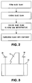
FIG. 2 is a schematic representation of a method for forming an article having a dual property microstructure; -
FIG. 3 is a schematic representation of a cooling system used in the method ofFIG. 2 ; -
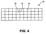
FIG. 4 illustrates a grate used in the cooling system ofFIG. 3 ; -
FIGS. 5 and 6 are graphs showing cooling rate curves for thin and thick sections of a blade blank preform; -
FIG. 7 is an SEM photomicrograph of a fast cooled section showing a fully lamellar microstructure; and -
FIG. 8 is an SEM photomicrograph of a slow cooled section showing a duplex microstructure consisting of fine gamma phase in a lamellar matrix. - It has been found that by combining part geometry with cooling, one is able to achieve dual property microstructure on gamma titanium blade blanks. Referring now to
Fig. 1 , a blade blank 10 is shown. The blade blank may be formed from a titanium alloy such as Gamma TiAl. One suitable alloy is TNM alloy (Ti - 43.5A1 - 4.0Nb - 1.0Mo - 0.1B, all in at%). The blade blank 10 may be cut for solution heat treatment in a preform geometry that is wide at thebase 12 where a root attachment may be located, and thin at thetop 14, where an airfoil tip may be located. The blade blank 10 has a triangular shape that is cut flat on thebottom 16. This allows the blade blank 10 to be stood upright with thebase 12 on the bottom and thetip 18 facing upward. - As can be seen from
Fig. 2 , after being formed, the blade blank 10 is subjected to a heat treatment. One exemplary heat treatment uses a temperature in the range of from 2240 deg F to 2320 deg F (1226.67 deg C to 1271.11 deg C) for a time period of one hour. The heat treatment may be performed in any suitable furnace such as an air furnace. Typically, the blade blank 10, when formed from a titanium alloy, will be removed from the furnace at a temperature of approximately 2300 degrees F (1260 degrees C). - The blade blank 10 thus formed is then placed onto a
grate 20 as shown inFig. 3 . Thegrate 20 may have a grid construction formed by a plurality of intersectingbars Figure 4 . Thegrate 24 may be formed from any suitable metallic material such as a nickel alloy sold under the name HAYNES 230. The grid construction may be such that there are a plurality ofopenings 26 in the grate. - Positioned in close proximity to the
grate 20 are a plurality ofcooling fans cooling fans cooling fan 28 could be aimed to blow cooling air at thetop part 14 of the blank and thecooling fan 30 may be aimed to blow cooling air at thebase 12 of the blade blank. By doing this, the thinnertop area 14 cools at a much greater rate than thewide base 12. This yields a dual property microstructure based on cooling rates. The dual property microstructure may be a fully lamellar microstructure at the fast cooled area and a duplex microstructure (consisting of a globular gamma phase in a lamellar matrix) at the slower cooling rate area. This will happen when the material is heat treated at a temperature above the alpha transus temperature (alternate plates of alpha 2 and gamma). For TNM gamma alloy, the alpha transus temperature is 2320 degrees Fahrenheit (1271.11 degrees Celsius). - Alternatively, one can achieve a duplex microstructure with different volume fraction of gamma phase if the heat treatment is done below the alpha transus temperature. Cooling at different rates follows if heat treatment will lead to the formation of a duplex microstructure. The end with the smaller area will experience a faster cooling rate which will develop lower volume fraction of globular gamma phase, while the end with the larger mass (slower cooling rate) will yield a higher gamma volume fraction.
- The
cooling fans grate 24. - Alternatively, the
cooling fans top area 14 of the blade blank 10, if desired, so that cooling air flows over thetop area 14 and cool thetop area 14 at a first cooling rate different from the cooling rate at which thebase 16 cools. - If desired, a first portion of the blade blank 10 may be cooled at a rate of 5.0 to 6.0 deg. F/sec. (2.78 to 3.33 deg C/sec), while a second portion of the blade blank 10 is cooled at a rate of 3.5 to 4.0 deg. F/sec (1.94 to 2.22 deg C/sec).
-
FIGS. 5 and 6 illustrate cooling rate curves for thin and thick sections as determined from thermocouple data. TC1 represents a thermocouple inserted in a thin section, such asportion 14 of the blade blank 10, and TC2 represents a thermocouple inserted in a thick section, such assection 12 of theblade blank 10. -
FIG. 7 is an SEM photomicrograph of a fast cooled section showing a fully lamellar microstructure.FIG. 8 is an SEM photomicrograph of a slow cooled section showing a duplex microstructure consisting of fine gamma phase in a lamellar matrix. - After cooling, the blade blank 10 can be formed into any suitable article using any suitable technique known in the art. For example, the blade blank 10 could be machined into a turbine engine component such as a low pressure turbine blade.
- The process of the present disclosure allows a dual property microstructure to be obtained without the cost of induction heating equipment, trial and error of fabricating induction coils to provided desired results. In addition to cost savings, other benefits include the ability to process material in locations that do not have this equipment, and repeatability. It is very easy to achieve repeatability, only needing to ensure starting temperature, and distance from cooling fans.
- In accordance with the present disclosure, there has been provided a gamma titanium dual property heat treat system and method. While the system and method have been described in the context of specific embodiments thereof, other unforeseeable modifications, variations, and alternatives may become apparent to those skilled in the art having read the foregoing description. Accordingly, it is intended to embrace those alternative, modifications, and variations as fall within the broad scope of the appended claims.
Claims (13)
- A method for forming a blank having a dual property microstructure, said method comprising the steps of:forming a blank having a narrow top portion and a wide base portion;heating said blank to an elevated temperature; andforming a dual property microstructure in said blank by cooling different portions of said blank at different cooling rates,characterised in that:said cooling step comprises placing said blank on a grate, providing a plurality of cooling fans for flowing cooling air over said blank; andsaid cooling step further comprises aiming a first one of said cooling fans at a first portion of said blank and aiming a second one of said cooling fans at a second portion of said blank.
- The method of claim 1, further comprising forming said cooled blank into a part.
- The method of claim 1 or 2, wherein said blank forming step comprises forming a blank having a triangular shape with said narrow top portion and said wide base portion.
- The method of claim 3, wherein said blank forming step further comprises forming a bottom which is flat so that blank can be stood up.
- The method of any preceding claim, wherein said heating step comprises heating said blank in a furnace.
- The method of any preceding claim, further comprising placing each of said cooling fans a distance from 1.0 to 3.0 feet (0.30 to 0.91 metres) from each side of said grate.
- The method of any preceding claim, wherein said cooling step further comprises cooling said first portion at a cooling rate in the range of 5.0 to 6.0 deg. F/sec (2.78 to 3.33 deg C/sec). and cooling said second portion at a cooling rate in the range of 3.5 to 4.0 deg. F/sec (1.94 to 2.22 deg C/sec).
- The method of any preceding claim, wherein said cooling step further comprises aiming a plurality of said fans at a first portion of said blank and blowing air over said first portion so that said first portion cools at a first cooling rate and allowing a second portion of said blank to cool at a second cooling rate different from said first cooling rate.
- A system for forming a part having a dual property microstructure, said system comprising:a blank formed from a metal alloy;means for heating said blank to an elevated temperature; andmeans for forming a dual property microstructure in said blank by cooling different portions of said blank at different cooling rates,characterised in that:said means for forming said dual property microstructure comprises a grate upon which said blank is placed in a heated condition and a plurality of cooling fans for cooling said blank; andwherein a first of said cooling fans is aimed at a first portion of said blank and a second of said cooling fans is aimed at a second portion of said blank.
- The system of claim 9, wherein said blank has a triangular shape with a narrow top portion, a wide base portion and a flat bottom.
- The system of claim 9 or 10, wherein said cooling fans are aimed at a first portion of said blank so that said first portion cools at a cooling rate different from the cooling rate of a second portion of said blank.
- The system of claim 9, 10 or 11, wherein the cooling fans are spaced by a distance in the range of from 1.0 to 3.0 feet (0.30 to 0.91 metres) from each side of the grate.
- The method or system of any preceding claim, wherein said blank is formed from a titanium aluminide.
Applications Claiming Priority (2)
| Application Number | Priority Date | Filing Date | Title |
|---|---|---|---|
| US13/590,446 US10006113B2 (en) | 2012-08-21 | 2012-08-21 | Gamma titanium dual property heat treat system and method |
| PCT/US2013/048395 WO2014031234A1 (en) | 2012-08-21 | 2013-06-28 | Gamma titanium dual property heat treat system and method |
Publications (3)
| Publication Number | Publication Date |
|---|---|
| EP2888384A1 EP2888384A1 (en) | 2015-07-01 |
| EP2888384A4 EP2888384A4 (en) | 2015-08-26 |
| EP2888384B1 true EP2888384B1 (en) | 2016-09-28 |
Family
ID=50146960
Family Applications (1)
| Application Number | Title | Priority Date | Filing Date |
|---|---|---|---|
| EP13831687.2A Active EP2888384B1 (en) | 2012-08-21 | 2013-06-28 | Gamma titanium dual property heat treat system and method |
Country Status (3)
| Country | Link |
|---|---|
| US (1) | US10006113B2 (en) |
| EP (1) | EP2888384B1 (en) |
| WO (1) | WO2014031234A1 (en) |
Families Citing this family (1)
| Publication number | Priority date | Publication date | Assignee | Title |
|---|---|---|---|---|
| CN105836453B (en) * | 2015-01-15 | 2019-03-26 | 深圳市韵腾激光科技有限公司 | It is cut by laser patch switch and method |
Family Cites Families (10)
| Publication number | Priority date | Publication date | Assignee | Title |
|---|---|---|---|---|
| DE2053947C3 (en) * | 1970-11-03 | 1975-01-16 | Demag Ag, 4100 Duisburg | Method and device for generating coolant jets for cooling metal cast strands |
| US5312497A (en) * | 1991-12-31 | 1994-05-17 | United Technologies Corporation | Method of making superalloy turbine disks having graded coarse and fine grains |
| US5558729A (en) | 1995-01-27 | 1996-09-24 | The United States Of America As Represented By The Secretary Of The Air Force | Method to produce gamma titanium aluminide articles having improved properties |
| US6425964B1 (en) | 1998-02-02 | 2002-07-30 | Chrysalis Technologies Incorporated | Creep resistant titanium aluminide alloys |
| ES2215513T3 (en) * | 2000-04-14 | 2004-10-16 | Ipsen International Gmbh | PROCEDURE AND DEVICE FOR THE THERMAL TREATMENT OF METAL WORK PIECES. |
| GB0215563D0 (en) | 2002-07-05 | 2002-08-14 | Rolls Royce Plc | A method of heat treating titanium aluminide |
| US7896986B2 (en) * | 2004-09-02 | 2011-03-01 | Siemens Energy, Inc. | Heat treatment of superalloy components |
| US7985307B2 (en) * | 2008-04-10 | 2011-07-26 | General Electric Company | Triple phase titanium fan and compressor blade and methods therefor |
| US8721812B2 (en) | 2009-04-07 | 2014-05-13 | Rolls-Royce Corporation | Techniques for controlling precipitate phase domain size in an alloy |
| WO2011008455A2 (en) | 2009-06-29 | 2011-01-20 | Borgwarner Inc. | Fatigue resistant cast titanium alloy articles |
-
2012
- 2012-08-21 US US13/590,446 patent/US10006113B2/en active Active
-
2013
- 2013-06-28 EP EP13831687.2A patent/EP2888384B1/en active Active
- 2013-06-28 WO PCT/US2013/048395 patent/WO2014031234A1/en not_active Ceased
Also Published As
| Publication number | Publication date |
|---|---|
| EP2888384A1 (en) | 2015-07-01 |
| WO2014031234A1 (en) | 2014-02-27 |
| US10006113B2 (en) | 2018-06-26 |
| EP2888384A4 (en) | 2015-08-26 |
| US20140053958A1 (en) | 2014-02-27 |
Similar Documents
| Publication | Publication Date | Title |
|---|---|---|
| JP6216881B2 (en) | Laminated production of single crystal alloy parts | |
| US9393620B2 (en) | Uber-cooled turbine section component made by additive manufacturing | |
| CN101772585B (en) | A method of heat treating a superalloy component and an alloy component | |
| BR102016019180A2 (en) | methods and apparatus for direct engraving of single crystal superalloys and metals | |
| EP2900964A1 (en) | Uber-cooled turbine section component made by additive manufacturing | |
| CN107815627A (en) | A kind of heat-treatment technology method of the 3D printing Inconel718 nickel-base alloys based on selective laser fusing | |
| CN114160796B (en) | Heat treatment process method for preparing turbine disk and turbine disk | |
| CA2929827C (en) | Turbine components with negative cte features | |
| CN106521121B (en) | A kind of heat treatment method of high temperature alloy steel | |
| EP2884182A1 (en) | A fabrication process and fabricated article | |
| US10006113B2 (en) | Gamma titanium dual property heat treat system and method | |
| US10105752B2 (en) | Turbine blade manufacturing method | |
| CN104152638B (en) | Micro-deformation quenching heat treatment process of cold work die steel thin workpiece | |
| CN105765085B (en) | Heat treatment method of stainless steel parts and manufacturing method of stainless steel forged products | |
| Abdulghani et al. | Modeling and simulation of laser assisted turning of hard steels | |
| CN105063310A (en) | Structure ultra-fine treatment process for high-chromium corrosion-resistant plastic mould steel | |
| EP3421621B1 (en) | Method for heat treating components | |
| RU2465367C1 (en) | Method for obtaining products of "blisk" structure from heat-resistant titanium alloys | |
| CN103773934B (en) | Thermal treatment method for eliminating structural heredity of high-toughness steel | |
| EP4411004A1 (en) | Selective heat treatment of metals using a coil-in-furnace system | |
| US20140110401A1 (en) | Method and system for localized heat treating using a susceptor | |
| CN105648156B (en) | A kind of heat treatment method of Chrominm-molybdenum-vanadium steel | |
| CN102534125A (en) | Metal heating processing technology | |
| CN105865382A (en) | Workpiece measuring device | |
| CN104419812A (en) | Heat treatment method of torsion plate forge piece of heavy duty gas turbine |
Legal Events
| Date | Code | Title | Description |
|---|---|---|---|
| PUAI | Public reference made under article 153(3) epc to a published international application that has entered the european phase |
Free format text: ORIGINAL CODE: 0009012 |
|
| 17P | Request for examination filed |
Effective date: 20150320 |
|
| AK | Designated contracting states |
Kind code of ref document: A1 Designated state(s): AL AT BE BG CH CY CZ DE DK EE ES FI FR GB GR HR HU IE IS IT LI LT LU LV MC MK MT NL NO PL PT RO RS SE SI SK SM TR |
|
| AX | Request for extension of the european patent |
Extension state: BA ME |
|
| RA4 | Supplementary search report drawn up and despatched (corrected) |
Effective date: 20150724 |
|
| RIC1 | Information provided on ipc code assigned before grant |
Ipc: C21D 1/62 20060101ALI20150720BHEP Ipc: C22F 1/18 20060101AFI20150720BHEP Ipc: C22C 21/00 20060101ALI20150720BHEP Ipc: C22C 14/00 20060101ALI20150720BHEP |
|
| DAX | Request for extension of the european patent (deleted) | ||
| GRAP | Despatch of communication of intention to grant a patent |
Free format text: ORIGINAL CODE: EPIDOSNIGR1 |
|
| INTG | Intention to grant announced |
Effective date: 20160413 |
|
| GRAS | Grant fee paid |
Free format text: ORIGINAL CODE: EPIDOSNIGR3 |
|
| GRAA | (expected) grant |
Free format text: ORIGINAL CODE: 0009210 |
|
| AK | Designated contracting states |
Kind code of ref document: B1 Designated state(s): AL AT BE BG CH CY CZ DE DK EE ES FI FR GB GR HR HU IE IS IT LI LT LU LV MC MK MT NL NO PL PT RO RS SE SI SK SM TR |
|
| REG | Reference to a national code |
Ref country code: GB Ref legal event code: FG4D |
|
| REG | Reference to a national code |
Ref country code: CH Ref legal event code: EP |
|
| REG | Reference to a national code |
Ref country code: CH Ref legal event code: PCOW Free format text: NEW ADDRESS: 10 FARM SPRINGS RD., FARMINGTON, CT 06032 (US) |
|
| REG | Reference to a national code |
Ref country code: AT Ref legal event code: REF Ref document number: 832829 Country of ref document: AT Kind code of ref document: T Effective date: 20161015 |
|
| RAP2 | Party data changed (patent owner data changed or rights of a patent transferred) |
Owner name: UNITED TECHNOLOGIES CORPORATION |
|
| REG | Reference to a national code |
Ref country code: IE Ref legal event code: FG4D |
|
| REG | Reference to a national code |
Ref country code: DE Ref legal event code: R096 Ref document number: 602013012300 Country of ref document: DE |
|
| REG | Reference to a national code |
Ref country code: LT Ref legal event code: MG4D |
|
| PG25 | Lapsed in a contracting state [announced via postgrant information from national office to epo] |
Ref country code: HR Free format text: LAPSE BECAUSE OF FAILURE TO SUBMIT A TRANSLATION OF THE DESCRIPTION OR TO PAY THE FEE WITHIN THE PRESCRIBED TIME-LIMIT Effective date: 20160928 Ref country code: RS Free format text: LAPSE BECAUSE OF FAILURE TO SUBMIT A TRANSLATION OF THE DESCRIPTION OR TO PAY THE FEE WITHIN THE PRESCRIBED TIME-LIMIT Effective date: 20160928 Ref country code: FI Free format text: LAPSE BECAUSE OF FAILURE TO SUBMIT A TRANSLATION OF THE DESCRIPTION OR TO PAY THE FEE WITHIN THE PRESCRIBED TIME-LIMIT Effective date: 20160928 Ref country code: NO Free format text: LAPSE BECAUSE OF FAILURE TO SUBMIT A TRANSLATION OF THE DESCRIPTION OR TO PAY THE FEE WITHIN THE PRESCRIBED TIME-LIMIT Effective date: 20161228 Ref country code: LT Free format text: LAPSE BECAUSE OF FAILURE TO SUBMIT A TRANSLATION OF THE DESCRIPTION OR TO PAY THE FEE WITHIN THE PRESCRIBED TIME-LIMIT Effective date: 20160928 |
|
| REG | Reference to a national code |
Ref country code: NL Ref legal event code: MP Effective date: 20160928 |
|
| REG | Reference to a national code |
Ref country code: AT Ref legal event code: MK05 Ref document number: 832829 Country of ref document: AT Kind code of ref document: T Effective date: 20160928 |
|
| PG25 | Lapsed in a contracting state [announced via postgrant information from national office to epo] |
Ref country code: NL Free format text: LAPSE BECAUSE OF FAILURE TO SUBMIT A TRANSLATION OF THE DESCRIPTION OR TO PAY THE FEE WITHIN THE PRESCRIBED TIME-LIMIT Effective date: 20160928 Ref country code: GR Free format text: LAPSE BECAUSE OF FAILURE TO SUBMIT A TRANSLATION OF THE DESCRIPTION OR TO PAY THE FEE WITHIN THE PRESCRIBED TIME-LIMIT Effective date: 20161229 Ref country code: SE Free format text: LAPSE BECAUSE OF FAILURE TO SUBMIT A TRANSLATION OF THE DESCRIPTION OR TO PAY THE FEE WITHIN THE PRESCRIBED TIME-LIMIT Effective date: 20160928 Ref country code: LV Free format text: LAPSE BECAUSE OF FAILURE TO SUBMIT A TRANSLATION OF THE DESCRIPTION OR TO PAY THE FEE WITHIN THE PRESCRIBED TIME-LIMIT Effective date: 20160928 |
|
| PG25 | Lapsed in a contracting state [announced via postgrant information from national office to epo] |
Ref country code: RO Free format text: LAPSE BECAUSE OF FAILURE TO SUBMIT A TRANSLATION OF THE DESCRIPTION OR TO PAY THE FEE WITHIN THE PRESCRIBED TIME-LIMIT Effective date: 20160928 Ref country code: EE Free format text: LAPSE BECAUSE OF FAILURE TO SUBMIT A TRANSLATION OF THE DESCRIPTION OR TO PAY THE FEE WITHIN THE PRESCRIBED TIME-LIMIT Effective date: 20160928 |
|
| PG25 | Lapsed in a contracting state [announced via postgrant information from national office to epo] |
Ref country code: BG Free format text: LAPSE BECAUSE OF FAILURE TO SUBMIT A TRANSLATION OF THE DESCRIPTION OR TO PAY THE FEE WITHIN THE PRESCRIBED TIME-LIMIT Effective date: 20161228 Ref country code: SM Free format text: LAPSE BECAUSE OF FAILURE TO SUBMIT A TRANSLATION OF THE DESCRIPTION OR TO PAY THE FEE WITHIN THE PRESCRIBED TIME-LIMIT Effective date: 20160928 Ref country code: PT Free format text: LAPSE BECAUSE OF FAILURE TO SUBMIT A TRANSLATION OF THE DESCRIPTION OR TO PAY THE FEE WITHIN THE PRESCRIBED TIME-LIMIT Effective date: 20170130 Ref country code: AT Free format text: LAPSE BECAUSE OF FAILURE TO SUBMIT A TRANSLATION OF THE DESCRIPTION OR TO PAY THE FEE WITHIN THE PRESCRIBED TIME-LIMIT Effective date: 20160928 Ref country code: ES Free format text: LAPSE BECAUSE OF FAILURE TO SUBMIT A TRANSLATION OF THE DESCRIPTION OR TO PAY THE FEE WITHIN THE PRESCRIBED TIME-LIMIT Effective date: 20160928 Ref country code: IS Free format text: LAPSE BECAUSE OF FAILURE TO SUBMIT A TRANSLATION OF THE DESCRIPTION OR TO PAY THE FEE WITHIN THE PRESCRIBED TIME-LIMIT Effective date: 20170128 Ref country code: SK Free format text: LAPSE BECAUSE OF FAILURE TO SUBMIT A TRANSLATION OF THE DESCRIPTION OR TO PAY THE FEE WITHIN THE PRESCRIBED TIME-LIMIT Effective date: 20160928 Ref country code: PL Free format text: LAPSE BECAUSE OF FAILURE TO SUBMIT A TRANSLATION OF THE DESCRIPTION OR TO PAY THE FEE WITHIN THE PRESCRIBED TIME-LIMIT Effective date: 20160928 Ref country code: BE Free format text: LAPSE BECAUSE OF FAILURE TO SUBMIT A TRANSLATION OF THE DESCRIPTION OR TO PAY THE FEE WITHIN THE PRESCRIBED TIME-LIMIT Effective date: 20160928 Ref country code: CZ Free format text: LAPSE BECAUSE OF FAILURE TO SUBMIT A TRANSLATION OF THE DESCRIPTION OR TO PAY THE FEE WITHIN THE PRESCRIBED TIME-LIMIT Effective date: 20160928 |
|
| REG | Reference to a national code |
Ref country code: DE Ref legal event code: R097 Ref document number: 602013012300 Country of ref document: DE |
|
| PG25 | Lapsed in a contracting state [announced via postgrant information from national office to epo] |
Ref country code: IT Free format text: LAPSE BECAUSE OF FAILURE TO SUBMIT A TRANSLATION OF THE DESCRIPTION OR TO PAY THE FEE WITHIN THE PRESCRIBED TIME-LIMIT Effective date: 20160928 |
|
| REG | Reference to a national code |
Ref country code: DE Ref legal event code: R082 Ref document number: 602013012300 Country of ref document: DE Representative=s name: SCHMITT-NILSON SCHRAUD WAIBEL WOHLFROM PATENTA, DE |
|
| PG25 | Lapsed in a contracting state [announced via postgrant information from national office to epo] |
Ref country code: DK Free format text: LAPSE BECAUSE OF FAILURE TO SUBMIT A TRANSLATION OF THE DESCRIPTION OR TO PAY THE FEE WITHIN THE PRESCRIBED TIME-LIMIT Effective date: 20160928 |
|
| PLBE | No opposition filed within time limit |
Free format text: ORIGINAL CODE: 0009261 |
|
| STAA | Information on the status of an ep patent application or granted ep patent |
Free format text: STATUS: NO OPPOSITION FILED WITHIN TIME LIMIT |
|
| 26N | No opposition filed |
Effective date: 20170629 |
|
| PG25 | Lapsed in a contracting state [announced via postgrant information from national office to epo] |
Ref country code: SI Free format text: LAPSE BECAUSE OF FAILURE TO SUBMIT A TRANSLATION OF THE DESCRIPTION OR TO PAY THE FEE WITHIN THE PRESCRIBED TIME-LIMIT Effective date: 20160928 |
|
| PG25 | Lapsed in a contracting state [announced via postgrant information from national office to epo] |
Ref country code: MC Free format text: LAPSE BECAUSE OF FAILURE TO SUBMIT A TRANSLATION OF THE DESCRIPTION OR TO PAY THE FEE WITHIN THE PRESCRIBED TIME-LIMIT Effective date: 20160928 |
|
| REG | Reference to a national code |
Ref country code: CH Ref legal event code: PL |
|
| REG | Reference to a national code |
Ref country code: FR Ref legal event code: ST Effective date: 20180228 |
|
| REG | Reference to a national code |
Ref country code: IE Ref legal event code: MM4A |
|
| PG25 | Lapsed in a contracting state [announced via postgrant information from national office to epo] |
Ref country code: LU Free format text: LAPSE BECAUSE OF NON-PAYMENT OF DUE FEES Effective date: 20170628 Ref country code: LI Free format text: LAPSE BECAUSE OF NON-PAYMENT OF DUE FEES Effective date: 20170630 Ref country code: CH Free format text: LAPSE BECAUSE OF NON-PAYMENT OF DUE FEES Effective date: 20170630 Ref country code: IE Free format text: LAPSE BECAUSE OF NON-PAYMENT OF DUE FEES Effective date: 20170628 |
|
| PG25 | Lapsed in a contracting state [announced via postgrant information from national office to epo] |
Ref country code: FR Free format text: LAPSE BECAUSE OF NON-PAYMENT OF DUE FEES Effective date: 20170630 |
|
| PG25 | Lapsed in a contracting state [announced via postgrant information from national office to epo] |
Ref country code: MT Free format text: LAPSE BECAUSE OF NON-PAYMENT OF DUE FEES Effective date: 20170628 |
|
| PG25 | Lapsed in a contracting state [announced via postgrant information from national office to epo] |
Ref country code: AL Free format text: LAPSE BECAUSE OF FAILURE TO SUBMIT A TRANSLATION OF THE DESCRIPTION OR TO PAY THE FEE WITHIN THE PRESCRIBED TIME-LIMIT Effective date: 20160928 |
|
| PG25 | Lapsed in a contracting state [announced via postgrant information from national office to epo] |
Ref country code: HU Free format text: LAPSE BECAUSE OF FAILURE TO SUBMIT A TRANSLATION OF THE DESCRIPTION OR TO PAY THE FEE WITHIN THE PRESCRIBED TIME-LIMIT; INVALID AB INITIO Effective date: 20130628 |
|
| PG25 | Lapsed in a contracting state [announced via postgrant information from national office to epo] |
Ref country code: CY Free format text: LAPSE BECAUSE OF FAILURE TO SUBMIT A TRANSLATION OF THE DESCRIPTION OR TO PAY THE FEE WITHIN THE PRESCRIBED TIME-LIMIT Effective date: 20160928 |
|
| PG25 | Lapsed in a contracting state [announced via postgrant information from national office to epo] |
Ref country code: MK Free format text: LAPSE BECAUSE OF FAILURE TO SUBMIT A TRANSLATION OF THE DESCRIPTION OR TO PAY THE FEE WITHIN THE PRESCRIBED TIME-LIMIT Effective date: 20160928 |
|
| PG25 | Lapsed in a contracting state [announced via postgrant information from national office to epo] |
Ref country code: TR Free format text: LAPSE BECAUSE OF FAILURE TO SUBMIT A TRANSLATION OF THE DESCRIPTION OR TO PAY THE FEE WITHIN THE PRESCRIBED TIME-LIMIT Effective date: 20160928 |
|
| REG | Reference to a national code |
Ref country code: DE Ref legal event code: R081 Ref document number: 602013012300 Country of ref document: DE Owner name: RAYTHEON TECHNOLOGIES CORPORATION (N.D.GES.D.S, US Free format text: FORMER OWNER: UNITED TECHNOLOGIES CORPORATION, HARTFORD, CONN., US |
|
| P01 | Opt-out of the competence of the unified patent court (upc) registered |
Effective date: 20230520 |
|
| PGFP | Annual fee paid to national office [announced via postgrant information from national office to epo] |
Ref country code: DE Payment date: 20250520 Year of fee payment: 13 |
|
| PGFP | Annual fee paid to national office [announced via postgrant information from national office to epo] |
Ref country code: GB Payment date: 20250520 Year of fee payment: 13 |