EP2887986B1 - Breathing assistance system with speech detection - Google Patents
Breathing assistance system with speech detection Download PDFInfo
- Publication number
- EP2887986B1 EP2887986B1 EP13766233.4A EP13766233A EP2887986B1 EP 2887986 B1 EP2887986 B1 EP 2887986B1 EP 13766233 A EP13766233 A EP 13766233A EP 2887986 B1 EP2887986 B1 EP 2887986B1
- Authority
- EP
- European Patent Office
- Prior art keywords
- patient
- speech
- flow
- valve
- ventilator
- Prior art date
- Legal status (The legal status is an assumption and is not a legal conclusion. Google has not performed a legal analysis and makes no representation as to the accuracy of the status listed.)
- Active
Links
Images



Classifications
-
- A—HUMAN NECESSITIES
- A61—MEDICAL OR VETERINARY SCIENCE; HYGIENE
- A61M—DEVICES FOR INTRODUCING MEDIA INTO, OR ONTO, THE BODY; DEVICES FOR TRANSDUCING BODY MEDIA OR FOR TAKING MEDIA FROM THE BODY; DEVICES FOR PRODUCING OR ENDING SLEEP OR STUPOR
- A61M16/00—Devices for influencing the respiratory system of patients by gas treatment, e.g. ventilators; Tracheal tubes
- A61M16/04—Tracheal tubes
- A61M16/0465—Tracheostomy tubes; Devices for performing a tracheostomy; Accessories therefor, e.g. masks, filters
- A61M16/0468—Tracheostomy tubes; Devices for performing a tracheostomy; Accessories therefor, e.g. masks, filters with valves at the proximal end limiting exhalation, e.g. during speaking or coughing
-
- A—HUMAN NECESSITIES
- A61—MEDICAL OR VETERINARY SCIENCE; HYGIENE
- A61M—DEVICES FOR INTRODUCING MEDIA INTO, OR ONTO, THE BODY; DEVICES FOR TRANSDUCING BODY MEDIA OR FOR TAKING MEDIA FROM THE BODY; DEVICES FOR PRODUCING OR ENDING SLEEP OR STUPOR
- A61M16/00—Devices for influencing the respiratory system of patients by gas treatment, e.g. ventilators; Tracheal tubes
- A61M16/0003—Accessories therefor, e.g. sensors, vibrators, negative pressure
- A61M16/0006—Accessories therefor, e.g. sensors, vibrators, negative pressure with means for creating vibrations in patients' airways
-
- A—HUMAN NECESSITIES
- A61—MEDICAL OR VETERINARY SCIENCE; HYGIENE
- A61M—DEVICES FOR INTRODUCING MEDIA INTO, OR ONTO, THE BODY; DEVICES FOR TRANSDUCING BODY MEDIA OR FOR TAKING MEDIA FROM THE BODY; DEVICES FOR PRODUCING OR ENDING SLEEP OR STUPOR
- A61M16/00—Devices for influencing the respiratory system of patients by gas treatment, e.g. ventilators; Tracheal tubes
- A61M16/021—Devices for influencing the respiratory system of patients by gas treatment, e.g. ventilators; Tracheal tubes operated by electrical means
-
- A—HUMAN NECESSITIES
- A61—MEDICAL OR VETERINARY SCIENCE; HYGIENE
- A61M—DEVICES FOR INTRODUCING MEDIA INTO, OR ONTO, THE BODY; DEVICES FOR TRANSDUCING BODY MEDIA OR FOR TAKING MEDIA FROM THE BODY; DEVICES FOR PRODUCING OR ENDING SLEEP OR STUPOR
- A61M16/00—Devices for influencing the respiratory system of patients by gas treatment, e.g. ventilators; Tracheal tubes
- A61M16/10—Preparation of respiratory gases or vapours
- A61M16/105—Filters
-
- A—HUMAN NECESSITIES
- A61—MEDICAL OR VETERINARY SCIENCE; HYGIENE
- A61M—DEVICES FOR INTRODUCING MEDIA INTO, OR ONTO, THE BODY; DEVICES FOR TRANSDUCING BODY MEDIA OR FOR TAKING MEDIA FROM THE BODY; DEVICES FOR PRODUCING OR ENDING SLEEP OR STUPOR
- A61M16/00—Devices for influencing the respiratory system of patients by gas treatment, e.g. ventilators; Tracheal tubes
- A61M16/20—Valves specially adapted to medical respiratory devices
-
- A—HUMAN NECESSITIES
- A61—MEDICAL OR VETERINARY SCIENCE; HYGIENE
- A61M—DEVICES FOR INTRODUCING MEDIA INTO, OR ONTO, THE BODY; DEVICES FOR TRANSDUCING BODY MEDIA OR FOR TAKING MEDIA FROM THE BODY; DEVICES FOR PRODUCING OR ENDING SLEEP OR STUPOR
- A61M16/00—Devices for influencing the respiratory system of patients by gas treatment, e.g. ventilators; Tracheal tubes
- A61M16/10—Preparation of respiratory gases or vapours
- A61M16/105—Filters
- A61M16/106—Filters in a path
- A61M16/107—Filters in a path in the inspiratory path
-
- A—HUMAN NECESSITIES
- A61—MEDICAL OR VETERINARY SCIENCE; HYGIENE
- A61M—DEVICES FOR INTRODUCING MEDIA INTO, OR ONTO, THE BODY; DEVICES FOR TRANSDUCING BODY MEDIA OR FOR TAKING MEDIA FROM THE BODY; DEVICES FOR PRODUCING OR ENDING SLEEP OR STUPOR
- A61M2205/00—General characteristics of the apparatus
- A61M2205/07—General characteristics of the apparatus having air pumping means
-
- A—HUMAN NECESSITIES
- A61—MEDICAL OR VETERINARY SCIENCE; HYGIENE
- A61M—DEVICES FOR INTRODUCING MEDIA INTO, OR ONTO, THE BODY; DEVICES FOR TRANSDUCING BODY MEDIA OR FOR TAKING MEDIA FROM THE BODY; DEVICES FOR PRODUCING OR ENDING SLEEP OR STUPOR
- A61M2205/00—General characteristics of the apparatus
- A61M2205/33—Controlling, regulating or measuring
- A61M2205/3331—Pressure; Flow
- A61M2205/3334—Measuring or controlling the flow rate
-
- A—HUMAN NECESSITIES
- A61—MEDICAL OR VETERINARY SCIENCE; HYGIENE
- A61M—DEVICES FOR INTRODUCING MEDIA INTO, OR ONTO, THE BODY; DEVICES FOR TRANSDUCING BODY MEDIA OR FOR TAKING MEDIA FROM THE BODY; DEVICES FOR PRODUCING OR ENDING SLEEP OR STUPOR
- A61M2205/00—General characteristics of the apparatus
- A61M2205/33—Controlling, regulating or measuring
- A61M2205/3375—Acoustical, e.g. ultrasonic, measuring means
-
- A—HUMAN NECESSITIES
- A61—MEDICAL OR VETERINARY SCIENCE; HYGIENE
- A61M—DEVICES FOR INTRODUCING MEDIA INTO, OR ONTO, THE BODY; DEVICES FOR TRANSDUCING BODY MEDIA OR FOR TAKING MEDIA FROM THE BODY; DEVICES FOR PRODUCING OR ENDING SLEEP OR STUPOR
- A61M2205/00—General characteristics of the apparatus
- A61M2205/35—Communication
-
- A—HUMAN NECESSITIES
- A61—MEDICAL OR VETERINARY SCIENCE; HYGIENE
- A61M—DEVICES FOR INTRODUCING MEDIA INTO, OR ONTO, THE BODY; DEVICES FOR TRANSDUCING BODY MEDIA OR FOR TAKING MEDIA FROM THE BODY; DEVICES FOR PRODUCING OR ENDING SLEEP OR STUPOR
- A61M2205/00—General characteristics of the apparatus
- A61M2205/75—General characteristics of the apparatus with filters
Definitions
- the present technology relates to one or more of the diagnosis, treatment and amelioration of respiratory disorders.
- the present technology relates to medical devices, and their use for treating respiratory disorders.
- WO 2006/133493 A1 describes a method of acclimatizing a user to provide continuous positive airway pressure therapy.
- US 2008/0060646 A1 describes a method of operating a ventilator assembly having inhalation and exhalation passages.
- US2008/0060646 A1 discloses a ventilator connected to a tracheostomy tube, the ventilator having a talking mode for facilitating speech.
- the respiratory system of the body facilitates gas exchange.
- the nose and mouth form the entrance to the airways of a patient.
- the airways include a series of branching tubes, which become narrower, shorter and more numerous as they penetrate deeper into the lung.
- the prime function of the lung is gas exchange, allowing oxygen to move from the air into the venous blood and carbon dioxide to move out.
- the trachea divides into right and left main bronchi, which further divide eventually into terminal bronchioles.
- the bronchi make up the conducting airways, and do not take part in gas exchange. Further divisions of the airways lead to the respiratory bronchioles, and eventually to the alveoli.
- the alveolated region of the lung is where the gas exchange takes place, and is referred to as the respiratory zone. See West, Respiratory Physiology- the Essentials.
- Cheyne-Stokes Respiration is a disorder of a patient's respiratory controller in which there are rhythmic alternating periods of waxing and waning ventilation, causing repetitive de-oxygenation and re-oxygenation of the arterial blood. It is possible that CSR is harmful because of the repetitive hypoxia. In some patients CSR is associated with repetitive arousal from sleep, which causes severe sleep disruption, increased sympathetic activity, and increased afterload. See US Patent 6,532,959 (Berthon-Jones ).
- Obesity Hyperventilation Syndrome is defined as the combination of severe obesity and awake chronic hypercapnia, in the absence of other known causes for hypoventilation. Symptoms include dyspnea, morning headache and excessive daytime sleepiness.
- COPD Chronic Obstructive Pulmonary Disease
- COPD encompasses any of a group of lower airway diseases that have certain characteristics in common. These include increased resistance to air movement, extended expiratory phase of respiration, and loss of the normal elasticity of the lung. Examples of COPD are emphysema and chronic bronchitis. COPD is caused by chronic tobacco smoking (primary risk factor), occupational exposures, air pollution and genetic factors. Symptoms include: dyspnea on exertion, chronic cough and sputum production.
- Neuromuscular Disease is a broad term that encompasses many diseases and ailments that impair the functioning of the muscles either directly via intrinsic muscle pathology, or indirectly via nerve pathology.
- Some NMD patients are characterised by progressive muscular impairment leading to loss of ambulation, being wheelchair-bound, swallowing difficulties, respiratory muscle weakness and, eventually, death from respiratory failure.
- Neuromuscular disorders can be divided into rapidly progressive and slowly progressive: (i) Rapidly progressive disorders: Characterised by muscle impairment that worsens over months and results in death within a few years (e.g.
- ALS Amyotrophic lateral sclerosis
- DMD Duchenne muscular dystrophy
- Variable or slowly progressive disorders Characterised by muscle impairment that worsens over years and only mildly reduces life expectancy (e.g. Limb girdle, Facioscapulohumeral and Myotonic muscular dystrophy).
- Symptoms of respiratory failure in NMD include: increasing generalised weakness, dysphagia, dyspnea on exertion and at rest, fatigue, sleepiness, morning headache, and difficulties with concentration and mood changes.
- Chest wall disorders are a group of thoracic deformities that result in inefficient coupling between the respiratory muscles and the thoracic cage.
- the disorders are usually characterised by a restrictive defect and share the potential of long term hypercapnic respiratory failure.
- Scoliosis and/or kyphoscoliosis may cause severe respiratory failure.
- Symptoms of respiratory failure include: dyspnea on exertion, peripheral oedema, orthopnea, repeated chest infections, morning headaches, fatigue, poor sleep quality and loss of appetite.
- Ventilation has been used to treat CSR, OHS, COPD, MD and Chest Wall disorders.
- the air at positive pressure for ventilation is typically supplied to the airway of a patient by a PAP device or ventilator such as a motor-driven blower.
- a PAP device or ventilator such as a motor-driven blower.
- the outlet of the blower is connected via a flexible delivery conduit to the airway of the patient.
- Tracheostomy is a surgical procedure in which an incision on the anterior of the neck is made in order to open an airway into the trachea of a patient. Through the resulting opening a tracheostomy tube is inserted into the patient's trachea in order to allow him to breathe without the use of his upper airways.
- a PAP device or ventilator used with such a tracheostomy tube can assist a patient by providing him with pressurised air or other breathable gas via the tube when the patient inhales, and by allowing exhaled air to be evacuated via the tube when the patient exhales.
- a valved ventilator While connected to a valved ventilator, e.g. under uncuffed tracheostomy, the patient may attempt to speak.
- the normal operation of the ventilator will impair the quality of that speech by allowing the exhaled air to pass through the tracheostomy tube instead of through the upper airway, where the vocal cords are located.
- Air being exhaled via a tracheostomy tube can impair speech from a patient under ventilation as the exhaled air is diverted from flowing through the patient's upper airway and along his vocal cords.
- a pressure below the vocal cords (between the lung and the vocal cords) above a minimum value of approximately 3 hPa is normally required. This is typically done in a non-tracheostomised person by contracting the vocal cords while there is air inside the lungs (after an inhalation). The pressure will then be the result of the normal exhalation of air through the vocal cords and then the mouth.
- PEEP Pressure End-Expiratory Pressure
- a non-return valve such as a Passy-Muir valve, is positioned along the conduit so that the only possible route for the exhaled air is via the upper airway.
- French patent application no. FR 2945217 relates to a breathing assistance device for a tracheostomy patient that is said to facilitate breathing and speech of the patient.
- the assembly has an expiration circuit with an outlet opening for passage of the air exhaled by the patient, and a valve for opening/closing the outlet opening. When the patient inhales, the valve closes the outlet opening and when the patient exhales the valve opens the outlet opening.
- the device is also provided with means for positive control to be actuated by the patient for selectively moving the valve into the closed position when the patient exhales, so that the exhalation is via the upper airway, i.e., when he wishes to speak, or to a state where exhalation is done via the tracheostomy tube, i.e., when he does not wish to speak.
- the present technology is directed towards providing medical devices used in the diagnosis, amelioration, treatment, or prevention of respiratory disorders having one or more of improved comfort, cost, efficacy, ease of use and manufacturability.
- the present technology particularly relates to a breathing assistance system and method that detects that a tracheostomised patient undergoing ventilation is speaking or attempting to speak, in response to which the breathing assistance system modifies its behaviour in order to facilitate or improve the quality of the patient's speech.
- the present technology includes a sensor such as a throat microphone that detects the vibration of the vocal cords, and a module that converts this vibration signal to a speech signal, e.g. a Boolean signal, indicating whether or not the patient is speaking or attempting to speak.
- This speech signal may be used by the breathing assistance system to conditionally modify its behaviour so as to facilitate or improve the quality of the patient's speech.
- the behaviour modification takes the form of facilitating the flow of exhaled air to the atmosphere via the upper airway of the patient, thereby at least partially suppressing the upstream flow of exhaled air via the tracheostomy tube. At least a substantial portion of the exhaled air therefore flows via the upper airway of the patient, and in particular through his vocal cords, to facilitate or improve the quality of the patient's speech
- the present technology may improve the quality of speech among a category of patients, including those that are not able to actively interact with a system, e.g. by pressing a button.
- the speech resulting from the use of the present technology is more intelligible and thus increases the patients' quality of life without requiring any modification of behaviour by the patients.
- One aspect of the present technology relates to provision of a minimum pressure of about 3 hPa below the vocal cords.
- a breathing assistance system comprising: a ventilator, a breathing lumen arranged to communicate a flow of air between the ventilator and a tracheostomy tube in the trachea of a patient, and a sensor configured to generate a vibration signal representing vocal cord vibrations of the patient, wherein the system is configured to facilitate the flow of exhaled air to the atmosphere via the upper airway of the patient in response to detection in the vibration signal of speech or attempted speech by the patient.
- a voice detection module configured to interact with a breathing assistance system, the module being adapted to: provide a vibration signal representing vocal cord vibrations of a patient whose ventilation is being supported by the breathing assistance system via a tracheostomy tube in the trachea of the patient; detect in the vibration signal speech or attempted speech by the patient; and in response to detection in the vibration signal of speech or attempted speech, modify the behaviour of the breathing assistance system so as to facilitate or improve the quality of the speech.
- a method of facilitating or improving the quality of speech by a tracheostomised patient comprising: supporting ventilation by the patient via a tracheostomy tube in the trachea of the patient, detecting speech or attempted speech by the patient, and facilitating the flow of exhaled air to the atmosphere via the upper airway of the patient in response to detection of speech or attempted speech by the patient.
- the present technology includes a breathing assistance system 10 for treating a respiratory disorder.
- the breathing assistance system 10 includes a ventilator 12 for supplying pressurised air or other breathable gas to a tracheostomised patient 5 via a breathing tube or lumen 14 connected to a tracheostomy tube 16 that is inserted into the trachea of the patient 5.
- the ventilator 12 is configured to support ventilation of the patient 5 by facilitating upstream and downstream flow of air via the tracheostomy tube 16 in synchrony with exhalation and inhalation portions respectively of breathing cycles of the patient 5.
- a voice detection module 20 includes a sensor 24 that is configured to generate vibration signals representing vibrations in the vocal cords of the patient 5.
- the voice detection module 20 optionally includes a speech detector 21 and optionally includes a filter 23.
- the speech detector 21 detects speech or attempted speech in the generated vibration signals, after optional bandpass filtering by the filter 23 to limit the vibration signal to the audible frequency range, upon which the voice detection module 20 prompts the ventilator 12 to conditionally modify its behaviour in order to facilitate or improve the quality of the patient's speech.
- the sensor 24 may be a contact vibration sensor.
- the sensor 24 is a throat microphone attached externally to the throat of the patient 5.
- the sensor 24 may be made insensitive to any audible noise except the vibrations generated by the patient 5 in contact with the sensor 24.
- the breathing assistance system 10 may therefore be seen to convert a vibration signal generated by the sensor 24 representing vibration of the vocal cords of the patient 5 to a speech signal indicating whether or not the patient is speaking or attempting to speak.
- the speech signal prompts the ventilator 12 to conditionally modify its behaviour in order to facilitate or improve the quality of the patient's speech.
- Such a breathing assistance system 10 may remove the need of the patient 5 to actively interact with the system 10 in order to speak intelligibly, and thus allow the ventilator 12 to have a safer / non-permanent behaviour or mode of operation that adjusts to the patient's respiratory needs.
- the voice detection module 20 may be a part of the breathing assistance system 10. In other embodiments, the voice detection module 20 may function as a separate module, not forming part of the breathing assistance system 10 but rather being configured to interact with the breathing assistance system 10 or with a system similar to system 10.
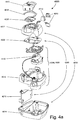
- a PAP device 4000 that may be used as the ventilator 12 in accordance with one aspect of the present technology comprises mechanical and pneumatic components 4100 and electrical components 4200.
- the PAP device preferably has an external housing 4010, preferably formed in two parts, an upper portion 4012 of the external housing 4010, and a lower portion 4014 of the external housing 4010.
- the external housing 4010 may include one or more panel(s) 4015.
- the PAP device 4000 comprises a chassis 4016 that supports one or more internal components of the PAP device 4000.
- a pneumatic block 4020 is supported by, or formed as part of the chassis 4016.
- the PAP device 4000 may include a handle 4018.
- the pneumatic path of the PAP device 4000 preferably comprises an inlet air filter 4112, an inlet muffler 4122, a controllable pressure device 4140 capable of supplying air at positive pressure (preferably a blower 4142), and an outlet muffler 4124.
- the preferred pneumatic block 4020 comprises a portion of the pneumatic path that is located within the external housing 4010.
- Electrical components 4200 may be mounted on a single Printed Circuit Board Assembly (PCBA) 4202 including an electrical power supply 4210 and one or more input devices 4220.
- PCBA Printed Circuit Board Assembly
- the PAP device 4000 may include more than one PCBA 4202.
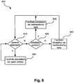
- Fig. 6 is a flow chart illustrating a method 600 of operation of the breathing assistance system 10 according to one form of the present technology.
- the method 600 is in the form of a continuous loop.
- step 610 the voice detection module 20 determines whether the patient is speaking or attempting to speak. If no speech or attempted speech is detected by the voice detection module 20 ("N" at step 610), the ventilator 12 at step 620 determines in conventional fashion whether the patient 5 is within the exhalation portion of a breathing cycle. If so ("Y" at step 620), the ventilator 12 facilitates exhalation (upstream air flow) via the tracheostomy tube 16 (step 630). Otherwise, i.e. if the patient 5 is determined to be within the inhalation portion of a breathing cycle (“N" at step 620), the ventilator 12 facilitates inhalation (downstream air flow) via the tracheostomy tube 16 (step 640). After both steps 630 and 640, the method 600 returns to step 610.
- the voice detection module 20 may send out a first command via a wireless or wired primary channel 26 that prompts the breathing assistance system 10 to modify its behaviour so as to facilitate or improve the quality of the patient's speech.
- this may be achieved by facilitating exhalation via the upper airway of the patient 5 (step 650), e.g. by increasing the resistance to flow through the tracheostomy tube 16. This has the effect of at least partially suppressing the upstream flow of exhaled air via the tracheostomy tube 16. At least a substantial portion of the exhaled air therefore flows via the upper airway of the patient 5, and in particular through his vocal cords, to facilitate or improve the quality of the patient's speech.
- the method 600 returns to step 610.
- the voice detection module 20 may send a second command via the primary channel 26 that prompts the ventilator 12 to cease the at least partial suppression of the upstream flow of exhaled air via the tracheostomy tube 16, and instead facilitate exhalation (upstream flow) via the tracheostomy tube 16 (step 630).
- the second command prompts the ventilator 12 to facilitate inhalation (downstream flow) via the tracheostomy tube 16 (step 640).
- vibration signals generated by the sensor 24 are optionally filtered and then analysed by the voice detection module 20 to determine if the vibration signals are indicative of speech or an attempt at speech.
- a vibration signal that is indicative of speech may exhibit one or more of the following characteristics:
- a vibration signal may be detected as a having one or more of the above characteristics throughout a single contiguous time window, of duration about 200 ms in one implementation, and / or multiple (e.g. two to three) times within an interval that is longer than the duration of the contiguous time window. In one implementation the interval is about 500 ms.
- the speech detection could be performed using the voiced / unvoiced threshold determined in conventional linear prediction coding. Speech detection may also be performed using Voice Activity Detection techniques as used e.g. in conventional mobile telephone technologies.
- Speech signals indicating speech or attempted speech may be generated all the time speech is detected, e.g. in accordance with the above criteria, and optionally also for a predetermined period Tg after the end of detection of speech, e.g. in accordance with the above criteria, particularly to take into account the pauses in, and unvoiced parts of, normal speech. At other times, speech signals indicating no speech or attempted speech may be generated.
- the period Tg may be configurable by a user of the system 10, or may be set to a fixed value, in one implementation equal to one second.
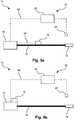
- Figs. 5a and 5b show two embodiments of a breathing assistance system 10 such as in Fig. 1 .
- the breathing assistance system 10 is adapted to support ventilation of the patient 5 by means of a valve 18 that can be urged between open and closed or substantially closed states in synchrony with exhalation and inhalation portions of the breathing cycle, in order to facilitate upstream and downstream flow of air in the tracheostomy tube 16 respectively as described above.
- the valve 18 may be replaced by an active vent.
- the valve 18 may be in various locations in the breathing assistance system 10, preferably in locations that are in communication with the tracheostomy tube 16 or the air flow path to and from the tracheostomy tube 16. In the embodiment of Fig.
- the valve 18 is arranged in the air flow path on and / or in communication with the breathing lumen 14.
- the valve 18 is arranged on and / or in communication with the ventilator 12, such as by being co-located with the ventilator 12.
- the voice detection module 20 is provided with a control or base unit 22 in communication with the sensor 24.
- the control unit 22 may comprise the filter 23 and the speech detector 21 of the voice detection module 20 as illustrated in Fig. 1 .
- the ventilator 12 is configured to support ventilation of the patient 5 via the tracheostomy tube 16 by facilitating a flow of pressurised air downstream to the tracheostomy tube 16 via the breathing lumen 14 during the inhalation portion of each breathing cycle (step 640). To accomplish this, the ventilator 12 urges the valve 18 towards its closed or substantially closed state to seal or substantially seal the breathing lumen 14 so that all or substantially all the downstream air flows through the tracheostomy tube 16.
- the ventilator 12 urges the valve 18 towards its open state in order to facilitate an upstream flow of exhaled air from the exhaling patient 5 via the tracheostomy tube 16, the breathing lumen 14, and the valve 18 to the atmosphere (step 630).
- the ventilator 12 urges the valve 18 towards its closed or substantially closed state to seal or substantially seal the breathing lumen 14 so that at least a substantial portion of the upstream flow is directed to the atmosphere via upper airway of the patient 5, to facilitate or improve the quality of the patient's speech (step 650).
- Transmission of commands to urge the valve 18 towards its open or closed states may occur via a secondary wireless or wired channel 28 between the ventilator 12 and the valve 18.
- the secondary channel 28 is illustrated in the embodiment of Fig. 5a wherein the valve 18 is located on and / or in communication with the breathing lumen 14, but is not illustrated (although it may still be present) in the embodiment of Fig. 5b wherein the valve 18 is located on and / or in communication with the ventilator 12.
- the primary channel 26 is illustrated in Figs. 5a and 5b as leading to the ventilator 12. However, the primary channel 26 may lead from the voice detection module 20 to any other part of the system 10 or means associated with the system 10 which may be adapted to control the interaction between the various parts of the breathing assistance system 10 such as between the ventilator 12 and valve 18 as described above.
- Fig. 5c illustrates a further embodiment of a breathing assistance system 10 containing a command module 30.
- the command module may alternatively function as a separate module that is not part of the breathing assistance system 10 but rather is configured to interact with the breathing assistance system 10 or with a system similar to the breathing assistance system 10.
- the command module 30 in the embodiment of Fig. 5c is located on / in the secondary channel 28, dividing it into first and second segments 32, 34 leading respectively to the ventilator 12 and the valve 18.
- the primary channel 26 in the embodiment of Fig. 5c enables communication between the voice detection module 20 and the command module 30 rather than between the voice detection module 20 and the ventilator 12, thus positioning the command module 30 as a hub or intersection point between the voice detection module 20, the ventilator 12, and the valve 18.
- commands communicated from the ventilator 12 towards the valve 18 along the first segment 32 of the secondary channel 28 may be intercepted at the command module 30, which is also configured to receive speech signals arriving over the primary channel 26 that indicate whether speech or an attempt at speech has been detected by the voice detection module 20.
- the command module 30 may forward this intercepted command (or a command of equivalent effect) over the second segment 34 of the secondary channel 28 to the valve 18 so that the exhaled air flow from the patient 5 will continue to be facilitated via the tracheostomy tube 16. If the speech signal arriving at the command module 30 via the primary channel 26 indicates that the patient 5 is speaking or attempting to speak, and a command to urge the valve 18 towards its open state has been intercepted, then the following may occur.
- the command module 30 may transmit via the second segment 34 of the secondary channel 28 to the valve 18 a command that is different from the intercepted command.
- the effect of the transmitted command is to urge the valve 18 towards its closed state to partially suppress the upstream flow of exhaled air via the tracheostomy tube 16, which causes at least a substantial portion of the exhaled air to flow to the atmosphere via the upper airway of the patient 5, and in particular through his vocal cords, to facilitate or improve the quality of the patient's speech.
- the system 10 is provided with a secondary valve 36 that is located between the outlet of the valve 18 and the atmosphere.
- the secondary valve 36 may be replaced by an active vent.
- the primary channel 26 in the embodiment of Fig. 5d may then enable communication between the control unit 22 and the secondary valve 36.
- a speech signal sent by the control unit 22 via the primary channel 26 and arriving at the secondary valve 36 instructs the secondary valve 36 to close or seal the outlet of the valve 18 (step 650).
- a subsequent or previous command sent by the ventilator 12 via the secondary channel 28 urges the valve 18 towards its open state in order to permit exhaled air to be discharged to the atmosphere via the tracheostomy tube 16 (step 640)
- the upstream flow of exhaled air via the tracheostomy tube 16 is at least partially suppressed. This causes at least a substantial portion of the exhaled air to flow via the upper airway of the patient 5, and in particular through his vocal cords, to facilitate or improve the quality of the patient's speech.
- a voice detection module 20 including the secondary valve 36, as illustrated in the embodiment of Fig. 5d may be particularly advantageous as an upgrade to or retrofitting of conventional breathing assistance systems that facilitates or improves the quality of speech of tracheostomised patients using the conventional breathing assistance systems.
- air supplied to a patient may be atmospheric air, and in other forms of the present technology atmospheric air may be supplemented with oxygen.
- Air circuit A conduit or tube constructed and arranged in use to deliver a supply of air or breathable gas between a PAP device and a patient interface.
- the air circuit may be in fluid connection with the outlet of the pneumatic block and the patient interface.
- the air circuit may be referred to as air delivery tube.
- Blower or flow generator A device that delivers a flow of air at a pressure above ambient pressure.
- Controller A device, or portion of a device that adjusts an output based on an input.
- one form of controller has a variable that is under control-the control variable- that constitutes the input to the device.
- the output of the device is a function of the current value of the control variable, and a set point for the variable.
- a servo-ventilator may include a controller that has ventilation as an input, a target ventilation as the set point, and level of pressure support as an output.
- Other forms of input may be one or more of oxygen saturation (SaO 2 ), partial pressure of carbon dioxide (PCO 2 ), movement, a signal from a photoplethysmogram, and peak flow.
- the set point of the controller may be one or more of fixed, variable or learned.
- the set point in a ventilator may be a long term average of the measured ventilation of a patient.
- Another ventilator may have a ventilation set point that changes with time.
- a pressure controller may be configured to control a blower or pump to deliver air at a particular pressure.
- Therapy in the present context may be one or more of positive pressure therapy, oxygen therapy, carbon dioxide therapy, control of dead space, and the administration of a drug.
- PAP device A device for providing a supply of air at positive pressure to the airway of a patient.
- breathing effort will be said to be the work done by a spontaneously breathing person attempting to breathe.
- Expiratory (exhalatory) portion of a breathing cycle The period from the start of expiratory flow to the start of inspiratory flow.
- Inspiratory (inhalatory) portion of a breathing cycle Preferably the period from the start of inspiratory flow to the start of expiratory flow will be taken to be the inspiratory portion of a breathing cycle.
- PEEP Positive End-Expiratory Pressure
- Respiratory flow, airflow, patient airflow, respiratory airflow (Qr): These synonymous terms may be understood to refer to the PAP device's estimate of respiratory airflow, as opposed to "true respiratory flow” or “true respiratory airflow”, which is the actual respiratory flow experienced by the patient, usually expressed in litres per minute.
- Ventilation A measure of the total amount of gas being exchanged by the patient's respiratory system, including both inspiratory and expiratory flow, per unit time. When expressed as a volume per minute, this quantity is often referred to as "minute ventilation”. Minute ventilation is sometimes given simply as a volume, understood to be the volume per minute.
- Flow rate The instantaneous volume (or mass) of air delivered per unit time. While flow rate and ventilation have the same dimensions of volume or mass per unit time, flow rate is measured over a much shorter period of time. Flow may be nominally positive for the inspiratory portion of a breathing cycle of a patient, and hence negative for the expiratory portion of the breathing cycle of a patient. In some cases, a reference to flow rate will be a reference to a scalar quantity, namely a quantity having magnitude only. In other cases, a reference to flow rate will be a reference to a vector quantity, namely a quantity having both magnitude and direction. Flow will be given the symbol Q. Total flow, Qt, is the flow of air leaving the PAP device.
- Vent flow, Qv is the flow of air leaving a vent to allow washout of exhaled gases.
- Leak flow, Ql is the flow rate of unintentional leak from a patient interface system.
- Respiratory flow, Qr is the flow of air that is received into the patient's respiratory system.
- Pressure Force per unit area. Pressure may be measured in a range of units, including cmH 2 O, g-f/cm 2 , hectopascal. 1cmH 2 O is equal to 1 g-f/cm 2 and is approximately 0.98 hectopascal. In this specification, unless otherwise stated, pressure is given in units of cmH 2 O.
- EPAP or EEP
- a base pressure to which a pressure varying within the breath is added to produce the desired mask pressure which the ventilator will attempt to achieve at a given time.
- IPAP desired mask pressure which the ventilator will attempt to achieve during the inspiratory portion of the breath.
- Servo-ventilator A ventilator that measures patient ventilation has a target ventilation, and which adjusts the level of pressure support to bring the patient ventilation towards the target ventilation.
- Ventilator A mechanical device that provides pressure support to a patient to perform some or all of the work of breathing.
- Diaphragm A sheet of muscle that extends across the bottom of the rib cage. The diaphragm separates the thoracic cavity, containing the heart, lungs and ribs, from the abdominal cavity. As the diaphragm contracts the volume of the thoracic cavity increases and air is drawn into the lungs.
- Larynx The larynx, or voice box houses the vocal folds and connects the inferior part of the pharynx (hypopharynx) with the trachea.
- Lungs The organs of respiration in humans.
- the conducting zone of the lungs contains the trachea, the bronchi, the bronchioles, and the terminal bronchioles.
- the respiratory zone contains the respiratory bronchioles, the alveolar ducts, and the alveoli.
- Nasal cavity The nasal cavity (or nasal fossa) is a large air filled space above and behind the nose in the middle of the face.
- the nasal cavity is divided in two by a vertical fin called the nasal septum.
- On the sides of the nasal cavity are three horizontal outgrowths called nasal conchae (singular "concha") or turbinates.
- nasal conchae singular "concha”
- turbinates To the front of the nasal cavity is the nose, while the back blends, via the choanae, into the nasopharynx.
- Pharynx The part of the throat situated immediately inferior to (below) the nasal cavity, and superior to the oesophagus and larynx.
- the pharynx is conventionally divided into three sections: the nasopharynx (epipharynx) (the nasal part of the pharynx), the oropharynx (mesopharynx) (the oral part of the pharynx), and the laryngopharynx (hypopharynx).
- any and all components herein described are understood to be capable of being manufactured and, as such, may be manufactured together or separately.
Landscapes
- Health & Medical Sciences (AREA)
- Pulmonology (AREA)
- Emergency Medicine (AREA)
- Engineering & Computer Science (AREA)
- Anesthesiology (AREA)
- Biomedical Technology (AREA)
- Heart & Thoracic Surgery (AREA)
- Hematology (AREA)
- Life Sciences & Earth Sciences (AREA)
- Animal Behavior & Ethology (AREA)
- General Health & Medical Sciences (AREA)
- Public Health (AREA)
- Veterinary Medicine (AREA)
- Prostheses (AREA)
- Measurement Of The Respiration, Hearing Ability, Form, And Blood Characteristics Of Living Organisms (AREA)
Description
- The present technology relates to one or more of the diagnosis, treatment and amelioration of respiratory disorders. In particular, the present technology relates to medical devices, and their use for treating respiratory disorders.
-
WO 2006/133493 A1 describes a method of acclimatizing a user to provide continuous positive airway pressure therapy.US 2008/0060646 A1 describes a method of operating a ventilator assembly having inhalation and exhalation passages. -
US2008/0060646 A1 discloses a ventilator connected to a tracheostomy tube, the ventilator having a talking mode for facilitating speech. - The respiratory system of the body facilitates gas exchange. The nose and mouth form the entrance to the airways of a patient.
- The airways include a series of branching tubes, which become narrower, shorter and more numerous as they penetrate deeper into the lung. The prime function of the lung is gas exchange, allowing oxygen to move from the air into the venous blood and carbon dioxide to move out. The trachea divides into right and left main bronchi, which further divide eventually into terminal bronchioles. The bronchi make up the conducting airways, and do not take part in gas exchange. Further divisions of the airways lead to the respiratory bronchioles, and eventually to the alveoli. The alveolated region of the lung is where the gas exchange takes place, and is referred to as the respiratory zone. See West, Respiratory Physiology- the Essentials.
- A range of respiratory disorders exist.
- Cheyne-Stokes Respiration (CSR) is a disorder of a patient's respiratory controller in which there are rhythmic alternating periods of waxing and waning ventilation, causing repetitive de-oxygenation and re-oxygenation of the arterial blood. It is possible that CSR is harmful because of the repetitive hypoxia. In some patients CSR is associated with repetitive arousal from sleep, which causes severe sleep disruption, increased sympathetic activity, and increased afterload. See
US Patent 6,532,959 (Berthon-Jones ). - Obesity Hyperventilation Syndrome (OHS) is defined as the combination of severe obesity and awake chronic hypercapnia, in the absence of other known causes for hypoventilation. Symptoms include dyspnea, morning headache and excessive daytime sleepiness.
- Chronic Obstructive Pulmonary Disease (COPD) encompasses any of a group of lower airway diseases that have certain characteristics in common. These include increased resistance to air movement, extended expiratory phase of respiration, and loss of the normal elasticity of the lung. Examples of COPD are emphysema and chronic bronchitis. COPD is caused by chronic tobacco smoking (primary risk factor), occupational exposures, air pollution and genetic factors. Symptoms include: dyspnea on exertion, chronic cough and sputum production.
- Neuromuscular Disease (NMD) is a broad term that encompasses many diseases and ailments that impair the functioning of the muscles either directly via intrinsic muscle pathology, or indirectly via nerve pathology. Some NMD patients are characterised by progressive muscular impairment leading to loss of ambulation, being wheelchair-bound, swallowing difficulties, respiratory muscle weakness and, eventually, death from respiratory failure. Neuromuscular disorders can be divided into rapidly progressive and slowly progressive: (i) Rapidly progressive disorders: Characterised by muscle impairment that worsens over months and results in death within a few years (e.g. Amyotrophic lateral sclerosis (ALS) and Duchenne muscular dystrophy (DMD) in teenagers); (ii) Variable or slowly progressive disorders: Characterised by muscle impairment that worsens over years and only mildly reduces life expectancy (e.g. Limb girdle, Facioscapulohumeral and Myotonic muscular dystrophy). Symptoms of respiratory failure in NMD include: increasing generalised weakness, dysphagia, dyspnea on exertion and at rest, fatigue, sleepiness, morning headache, and difficulties with concentration and mood changes.
- Chest wall disorders are a group of thoracic deformities that result in inefficient coupling between the respiratory muscles and the thoracic cage. The disorders are usually characterised by a restrictive defect and share the potential of long term hypercapnic respiratory failure. Scoliosis and/or kyphoscoliosis may cause severe respiratory failure. Symptoms of respiratory failure include: dyspnea on exertion, peripheral oedema, orthopnea, repeated chest infections, morning headaches, fatigue, poor sleep quality and loss of appetite.
- Ventilation has been used to treat CSR, OHS, COPD, MD and Chest Wall disorders.
- The air at positive pressure for ventilation is typically supplied to the airway of a patient by a PAP device or ventilator such as a motor-driven blower. The outlet of the blower is connected via a flexible delivery conduit to the airway of the patient.
- Tracheostomy is a surgical procedure in which an incision on the anterior of the neck is made in order to open an airway into the trachea of a patient. Through the resulting opening a tracheostomy tube is inserted into the patient's trachea in order to allow him to breathe without the use of his upper airways.
- A PAP device or ventilator used with such a tracheostomy tube can assist a patient by providing him with pressurised air or other breathable gas via the tube when the patient inhales, and by allowing exhaled air to be evacuated via the tube when the patient exhales.
- One known ventilator suitable for tracheostomy patients is the Elisée, manufactured by ResMed.
- While connected to a valved ventilator, e.g. under uncuffed tracheostomy, the patient may attempt to speak. The normal operation of the ventilator will impair the quality of that speech by allowing the exhaled air to pass through the tracheostomy tube instead of through the upper airway, where the vocal cords are located.
- Air being exhaled via a tracheostomy tube can impair speech from a patient under ventilation as the exhaled air is diverted from flowing through the patient's upper airway and along his vocal cords. To enable speech, a pressure below the vocal cords (between the lung and the vocal cords) above a minimum value of approximately 3 hPa is normally required. This is typically done in a non-tracheostomised person by contracting the vocal cords while there is air inside the lungs (after an inhalation). The pressure will then be the result of the normal exhalation of air through the vocal cords and then the mouth. On a tracheostomised patient, however, most of the exhaled air is not routed through the upper airway as the tracheostomy tube is located below the vocal cords, and it is easier for the air to pass through the exhalation valve of the breathing assistance system than through the upper airway.
- According to an existing solution, the usual value of PEEP (Positive End-Expiratory Pressure) is increased by the PAP device so that the majority of exhaled air is redirected along the upper airway. According to another solution, a non-return valve, such as a Passy-Muir valve, is positioned along the conduit so that the only possible route for the exhaled air is via the upper airway.
- French patent application no.
FR 2945217 - Most of the known solutions are permanent, i.e. they are kept constant throughout the therapy. Although allowing the patient to speak, they run counter to the whole purpose of tracheostomy. Only the device according to
FR 2945217 - The present invention is defined by the scope of its claims.
- The present technology is directed towards providing medical devices used in the diagnosis, amelioration, treatment, or prevention of respiratory disorders having one or more of improved comfort, cost, efficacy, ease of use and manufacturability.
- The present technology particularly relates to a breathing assistance system and method that detects that a tracheostomised patient undergoing ventilation is speaking or attempting to speak, in response to which the breathing assistance system modifies its behaviour in order to facilitate or improve the quality of the patient's speech.
- Preferably, the present technology includes a sensor such as a throat microphone that detects the vibration of the vocal cords, and a module that converts this vibration signal to a speech signal, e.g. a Boolean signal, indicating whether or not the patient is speaking or attempting to speak. This speech signal may be used by the breathing assistance system to conditionally modify its behaviour so as to facilitate or improve the quality of the patient's speech. Preferably, the behaviour modification takes the form of facilitating the flow of exhaled air to the atmosphere via the upper airway of the patient, thereby at least partially suppressing the upstream flow of exhaled air via the tracheostomy tube. At least a substantial portion of the exhaled air therefore flows via the upper airway of the patient, and in particular through his vocal cords, to facilitate or improve the quality of the patient's speech
- Once the patient has the breathing assistance system, particularly the sensor, according to the present technology in place, no more intervention is required from the patient in order to speak intelligibly. In particular, the present technology may improve the quality of speech among a category of patients, including those that are not able to actively interact with a system, e.g. by pressing a button. The speech resulting from the use of the present technology is more intelligible and thus increases the patients' quality of life without requiring any modification of behaviour by the patients.
- One aspect of the present technology relates to provision of a minimum pressure of about 3 hPa below the vocal cords.
- According to one aspect of the present technology, there is disclosed a breathing assistance system comprising: a ventilator, a breathing lumen arranged to communicate a flow of air between the ventilator and a tracheostomy tube in the trachea of a patient, and a sensor configured to generate a vibration signal representing vocal cord vibrations of the patient, wherein the system is configured to facilitate the flow of exhaled air to the atmosphere via the upper airway of the patient in response to detection in the vibration signal of speech or attempted speech by the patient.
- According to one aspect of the present technology, there is disclosed a voice detection module configured to interact with a breathing assistance system, the module being adapted to: provide a vibration signal representing vocal cord vibrations of a patient whose ventilation is being supported by the breathing assistance system via a tracheostomy tube in the trachea of the patient; detect in the vibration signal speech or attempted speech by the patient; and in response to detection in the vibration signal of speech or attempted speech, modify the behaviour of the breathing assistance system so as to facilitate or improve the quality of the speech.
- According to one aspect of the present technology, there is disclosed a method of facilitating or improving the quality of speech by a tracheostomised patient, the method comprising: supporting ventilation by the patient via a tracheostomy tube in the trachea of the patient, detecting speech or attempted speech by the patient, and facilitating the flow of exhaled air to the atmosphere via the upper airway of the patient in response to detection of speech or attempted speech by the patient.
- Additional and/or alternative aspects relate to:
- 1. A breathing assisting system comprising: a ventilator, a tracheostomy tube for communicating between the ventilator and a trachea of a patient, and a sensor for monitoring vocal cord vibrations, wherein the system is adapted to at least partially suppress flow of expelled air via the tube in response to detection of vibration indicative of speech.
- 2. The system according to aspect 1 and comprising a valve in communication with the tube via which the expelled air can flow, and the at least partial suppression of flow of the expelled air via the tube comprises at least partially closing the valve.
- 3. The system according to aspects 1 or 2 and being adapted to urge the ventilator to apply positive pressure at the tube to at least contribute to the at least partial suppression of flow of the expelled air via the tube.
- 4. The system according to any one of the preceding aspects, wherein the sensor comprises a contact vibration sensor.
- 5. The system according to any one of the preceding aspects, wherein the sensor is throat microphone preferably to be attached externally to the throat of the patient.
- 6. The system according to
aspects 4 or 5, wherein the sensor is sensitive only to vibrations generated by the patient in contact with the sensor. - 7. The system according to anyone of the preceding aspects and being adapted to release the at least partial suppression to flow after cessation of detection of vocal cord vibrations indicative of speech.
- 8. The system according to aspect 7, wherein the release occurs after a given period of time has passed from the last detection of vocal cord vibrations indicative of speech.
- 9. The system according to aspect 8, wherein the given period of time is 1 second.
- 10. The system according to anyone of the preceding aspects and comprising means for receiving monitored signals from the sensor, and wherein a detection of vibration indicative of speech is determined by the means.
- 11. The system according to
aspect 10, wherein the detection of vibration indicative of speech by the means is according to the vibration being within a range of 100Hz to 3kHz. - 12. The system according to
aspects 10 or 11, wherein the detection of vibration indicative of speech by the means is according to the vibration being detected present in a timed window of at least 200 ms. - 13. The system according to
aspects 10 or 11, wherein the detection of vibration indicative of speech by the means is according to the vibration occurring between 2 to 3 times in 500 ms. - 14. The system according to aspect 2 and being adapted to support inspiration and exhalation breathing cycles of the patient, and wherein at least during an end of an inspiration cycle the valve is closed.
- 15. The system according to
aspect 14, wherein during a given time window at a beginning of a subsequent exhalation cycle the valve is still closed. - 16. A voice detection module for interacting with a breathing assisting system, the module being adapted to: receive monitored signals of vocal cord vibrations of a patient, detect from the monitored signals vibrations indicative of speech, and send a first communication to the breathing assisting system in response to detection of vibration indicative of speech.
- 17. The voice detection module of
aspect 16 and being adapted to send a second communication to the breathing assisting system after ceasing to detect vibrations indicative of speech. - 18. The voice detection module of aspect 17, wherein second communication is sent after a given period of time has passed from the last detection of vocal cord vibrations indicative of speech.
- 19. The voice detection module of
aspect 18, wherein the given period of time is 1 second. - 20. The voice detection module of anyone of
aspects 16 to 19, wherein the detection of vibration indicative of speech is according to the vibration being within a range of 100Hz to 3kHz. - 21. The voice detection module of anyone of
aspects 16 to 20, wherein the detection of vibration indicative of speech is according to the vibration being detected present in a timed window of at least 200 ms. - 22. The voice detection module of anyone of
aspects 16 to 20 wherein the detection of vibration indicative of speech is according to the vibration occurring between 2 to 3 times in 500 ms. - 23. A command module for interacting with: a voice detection module monitoring a patient, and a breathing assisting system of the type comprising a tracheostomy tube and an exhalation valve through which air exhaled via the tube from the patient can exit, the command module being adapted to: intercept commands communicated in the system towards the valve, receive signals from the voice detection module, and send a closing command to the valve if receiving a given signal that is indicative of speech even though an intercepted command at or prior to the given signal was an opening command.
- 24. A command module for interacting with: a voice detection module monitoring a patient, and a breathing assisting system comprising a tracheostomy tube, the command module being adapted to: intercept commands in the system aimed at affecting the flow via the tube, receive signals from the voice detection module, and in response to a given signal indicative of speech at least partially suppress the flow of expelled air via the tube from the patient even though an intercepted command at or prior to the given signal was to affect the flow differently.
- Of course, portions of the aspects and/or claims may form sub-aspects of the present technology. Also, various ones of the claims, sub-aspects and/or aspects may be combined in various manners and also constitute additional aspects or sub-aspects of the present technology.
- Other features of the technology will be apparent from consideration of the information contained in the following detailed description, abstract, drawings and claims.
- The present technology is illustrated by way of example, and not by way of limitation, in the figures of the accompanying drawings, in which like reference numerals refer to similar elements including:
-
Fig. 1 shows general components of a breathing assistance system in accordance with one form of the present technology. -
Fig. 2 shows an overview of a human respiratory system including the nasal and oral cavities, the larynx, vocal folds (vocal cords), oesophagus, trachea, bronchus, lung, alveolar sacs, heart and diaphragm. -
Fig. 3 shows a detailed view of a human upper airway including the nasal cavity, nasal bone, lateral nasal cartilage, greater alar cartilage, nostril, lip superior, lip inferior, larynx, hard palate, soft palate, oropharynx, tongue, epiglottis, vocal folds, oesophagus and trachea. -
Fig. 4a shows a PAP device as used in a breathing assistance system such as inFig. 1 in accordance with one form of the present technology. -
Fig. 5a shows a breathing assistance system such as inFig. 1 in more detail in accordance with one embodiment of the present technology. -
Fig. 5b shows a breathing assistance system such as inFig. 1 in more detail in accordance with another embodiment of the present technology. -
Fig. 5c shows a breathing assistance system such as inFig. 1 in more detail in accordance with yet another embodiment of the present technology. -
Fig. 5d shows a breathing assistance system such as inFig. 1 in more detail in accordance with yet a further embodiment of the present technology. -
Fig. 6 is a flow chart illustrating a method of operation of a breathing assistance system such as inFig. 1 . - Before the present technology is described in further detail, it is to be understood that the technology is not limited to the particular examples described herein, which may vary. It is also to be understood that the terminology used in this disclosure is for the purpose of describing only the particular examples discussed herein, and is not intended to be limiting.
- In one form, the present technology includes a
breathing assistance system 10 for treating a respiratory disorder. Thebreathing assistance system 10 includes aventilator 12 for supplying pressurised air or other breathable gas to atracheostomised patient 5 via a breathing tube orlumen 14 connected to atracheostomy tube 16 that is inserted into the trachea of thepatient 5. Theventilator 12 is configured to support ventilation of thepatient 5 by facilitating upstream and downstream flow of air via thetracheostomy tube 16 in synchrony with exhalation and inhalation portions respectively of breathing cycles of thepatient 5. - A
voice detection module 20 includes asensor 24 that is configured to generate vibration signals representing vibrations in the vocal cords of thepatient 5. Thevoice detection module 20 optionally includes aspeech detector 21 and optionally includes afilter 23. Thespeech detector 21 detects speech or attempted speech in the generated vibration signals, after optional bandpass filtering by thefilter 23 to limit the vibration signal to the audible frequency range, upon which thevoice detection module 20 prompts theventilator 12 to conditionally modify its behaviour in order to facilitate or improve the quality of the patient's speech. - The
sensor 24 may be a contact vibration sensor. In one such implementation, thesensor 24 is a throat microphone attached externally to the throat of thepatient 5. Thesensor 24 may be made insensitive to any audible noise except the vibrations generated by thepatient 5 in contact with thesensor 24. - The
breathing assistance system 10 may therefore be seen to convert a vibration signal generated by thesensor 24 representing vibration of the vocal cords of thepatient 5 to a speech signal indicating whether or not the patient is speaking or attempting to speak. The speech signal prompts theventilator 12 to conditionally modify its behaviour in order to facilitate or improve the quality of the patient's speech. Such abreathing assistance system 10 may remove the need of thepatient 5 to actively interact with thesystem 10 in order to speak intelligibly, and thus allow theventilator 12 to have a safer / non-permanent behaviour or mode of operation that adjusts to the patient's respiratory needs. - In some embodiments of the
breathing assistance system 10, thevoice detection module 20 may be a part of thebreathing assistance system 10. In other embodiments, thevoice detection module 20 may function as a separate module, not forming part of thebreathing assistance system 10 but rather being configured to interact with thebreathing assistance system 10 or with a system similar tosystem 10. - A
PAP device 4000 that may be used as theventilator 12 in accordance with one aspect of the present technology comprises mechanical and pneumatic components 4100 andelectrical components 4200. The PAP device preferably has anexternal housing 4010, preferably formed in two parts, anupper portion 4012 of theexternal housing 4010, and alower portion 4014 of theexternal housing 4010. In alternative forms, theexternal housing 4010 may include one or more panel(s) 4015. Preferably thePAP device 4000 comprises achassis 4016 that supports one or more internal components of thePAP device 4000. In one form a pneumatic block 4020 is supported by, or formed as part of thechassis 4016. ThePAP device 4000 may include ahandle 4018. - The pneumatic path of the
PAP device 4000 preferably comprises aninlet air filter 4112, an inlet muffler 4122, a controllable pressure device 4140 capable of supplying air at positive pressure (preferably a blower 4142), and an outlet muffler 4124. - The preferred pneumatic block 4020 comprises a portion of the pneumatic path that is located within the
external housing 4010. -
Electrical components 4200 may be mounted on a single Printed Circuit Board Assembly (PCBA) 4202 including anelectrical power supply 4210 and one ormore input devices 4220. In an alternative form, thePAP device 4000 may include more than onePCBA 4202. -
Fig. 6 is a flow chart illustrating amethod 600 of operation of thebreathing assistance system 10 according to one form of the present technology. Themethod 600 is in the form of a continuous loop. - In
step 610, thevoice detection module 20 determines whether the patient is speaking or attempting to speak. If no speech or attempted speech is detected by the voice detection module 20 ("N" at step 610), theventilator 12 atstep 620 determines in conventional fashion whether thepatient 5 is within the exhalation portion of a breathing cycle. If so ("Y" at step 620), theventilator 12 facilitates exhalation (upstream air flow) via the tracheostomy tube 16 (step 630). Otherwise, i.e. if thepatient 5 is determined to be within the inhalation portion of a breathing cycle ("N" at step 620), theventilator 12 facilitates inhalation (downstream air flow) via the tracheostomy tube 16 (step 640). After bothsteps method 600 returns to step 610. - Upon an affirmative detection of speech or attempted speech by the voice detection module 20 ("Y" at step 610), the
voice detection module 20 may send out a first command via a wireless or wiredprimary channel 26 that prompts thebreathing assistance system 10 to modify its behaviour so as to facilitate or improve the quality of the patient's speech. In one implementation, this may be achieved by facilitating exhalation via the upper airway of the patient 5 (step 650), e.g. by increasing the resistance to flow through thetracheostomy tube 16. This has the effect of at least partially suppressing the upstream flow of exhaled air via thetracheostomy tube 16. At least a substantial portion of the exhaled air therefore flows via the upper airway of thepatient 5, and in particular through his vocal cords, to facilitate or improve the quality of the patient's speech. Afterstep 650, themethod 600 returns to step 610. - Once speech or attempted speech is no longer detected ("N" at step 610), or has not been detected for a predetermined period of time, if the
ventilator 12 determines that thepatient 5 is still within the exhalation portion of a breathing cycle ("Y" at step 620), thevoice detection module 20 may send a second command via theprimary channel 26 that prompts theventilator 12 to cease the at least partial suppression of the upstream flow of exhaled air via thetracheostomy tube 16, and instead facilitate exhalation (upstream flow) via the tracheostomy tube 16 (step 630). Otherwise, i.e. if thepatient 5 is determined to be within the inhalation portion of a new breathing cycle ("N" at step 620), the second command prompts theventilator 12 to facilitate inhalation (downstream flow) via the tracheostomy tube 16 (step 640). - According to the operation of the
breathing assistance system 10, as in for example themethod 600, vibration signals generated by thesensor 24 are optionally filtered and then analysed by thevoice detection module 20 to determine if the vibration signals are indicative of speech or an attempt at speech. A vibration signal that is indicative of speech may exhibit one or more of the following characteristics: - Quasi-periodic (sometimes called quasi-harmonic), denoting a waveform that is virtually periodic microscopically, but not necessarily periodic macroscopically, i.e. a waveform in which any one period is virtually identical to its adjacent periods but differing in frequency spectrum from periods much farther away in time (on the scale of a typical phoneme), and non-stationary (denoting that the quasi-periodic signal is limited in time), corresponding to voiced speech (e.g. voiced phonemes such as vowels).
- Substantially within a range of audible frequencies (e.g. about 70 Hz to about 3 kHz), wherein preferably vibrations in the vocal cords have fundamental frequencies typically between about 80 Hz and about 300 Hz.
- To be deemed indicative of speech, a vibration signal may be detected as a having one or more of the above characteristics throughout a single contiguous time window, of duration about 200 ms in one implementation, and / or multiple (e.g. two to three) times within an interval that is longer than the duration of the contiguous time window. In one implementation the interval is about 500 ms. In addition or alternatively, the speech detection could be performed using the voiced / unvoiced threshold determined in conventional linear prediction coding. Speech detection may also be performed using Voice Activity Detection techniques as used e.g. in conventional mobile telephone technologies.
- Speech signals indicating speech or attempted speech may be generated all the time speech is detected, e.g. in accordance with the above criteria, and optionally also for a predetermined period Tg after the end of detection of speech, e.g. in accordance with the above criteria, particularly to take into account the pauses in, and unvoiced parts of, normal speech. At other times, speech signals indicating no speech or attempted speech may be generated. The period Tg may be configurable by a user of the
system 10, or may be set to a fixed value, in one implementation equal to one second. -
Figs. 5a and 5b show two embodiments of abreathing assistance system 10 such as inFig. 1 . Absent any detected speech, thebreathing assistance system 10 is adapted to support ventilation of thepatient 5 by means of avalve 18 that can be urged between open and closed or substantially closed states in synchrony with exhalation and inhalation portions of the breathing cycle, in order to facilitate upstream and downstream flow of air in thetracheostomy tube 16 respectively as described above. In a variation, thevalve 18 may be replaced by an active vent. Thevalve 18 may be in various locations in thebreathing assistance system 10, preferably in locations that are in communication with thetracheostomy tube 16 or the air flow path to and from thetracheostomy tube 16. In the embodiment ofFig. 5a , thevalve 18 is arranged in the air flow path on and / or in communication with thebreathing lumen 14. In the embodiment ofFig. 5b , thevalve 18 is arranged on and / or in communication with theventilator 12, such as by being co-located with theventilator 12. - In
Figs. 5a and 5b , thevoice detection module 20 is provided with a control orbase unit 22 in communication with thesensor 24. Thecontrol unit 22 may comprise thefilter 23 and thespeech detector 21 of thevoice detection module 20 as illustrated inFig. 1 . - As described above in relation to the
method 600, theventilator 12 is configured to support ventilation of thepatient 5 via thetracheostomy tube 16 by facilitating a flow of pressurised air downstream to thetracheostomy tube 16 via thebreathing lumen 14 during the inhalation portion of each breathing cycle (step 640). To accomplish this, theventilator 12 urges thevalve 18 towards its closed or substantially closed state to seal or substantially seal thebreathing lumen 14 so that all or substantially all the downstream air flows through thetracheostomy tube 16. During the exhalation portion of each breathing cycle, absent any detection of speech or attempted speech, theventilator 12 urges thevalve 18 towards its open state in order to facilitate an upstream flow of exhaled air from the exhalingpatient 5 via thetracheostomy tube 16, thebreathing lumen 14, and thevalve 18 to the atmosphere (step 630). - If speech or attempted speech is detected by the
voice detection module 20, theventilator 12 urges thevalve 18 towards its closed or substantially closed state to seal or substantially seal thebreathing lumen 14 so that at least a substantial portion of the upstream flow is directed to the atmosphere via upper airway of thepatient 5, to facilitate or improve the quality of the patient's speech (step 650). - Transmission of commands to urge the
valve 18 towards its open or closed states may occur via a secondary wireless or wiredchannel 28 between theventilator 12 and thevalve 18. Thesecondary channel 28 is illustrated in the embodiment ofFig. 5a wherein thevalve 18 is located on and / or in communication with thebreathing lumen 14, but is not illustrated (although it may still be present) in the embodiment ofFig. 5b wherein thevalve 18 is located on and / or in communication with theventilator 12. - The
primary channel 26 is illustrated inFigs. 5a and 5b as leading to theventilator 12. However, theprimary channel 26 may lead from thevoice detection module 20 to any other part of thesystem 10 or means associated with thesystem 10 which may be adapted to control the interaction between the various parts of thebreathing assistance system 10 such as between theventilator 12 andvalve 18 as described above. -
Fig. 5c illustrates a further embodiment of abreathing assistance system 10 containing acommand module 30. The command module may alternatively function as a separate module that is not part of thebreathing assistance system 10 but rather is configured to interact with thebreathing assistance system 10 or with a system similar to thebreathing assistance system 10. Thecommand module 30 in the embodiment ofFig. 5c is located on / in thesecondary channel 28, dividing it into first andsecond segments ventilator 12 and thevalve 18. Theprimary channel 26 in the embodiment ofFig. 5c enables communication between thevoice detection module 20 and thecommand module 30 rather than between thevoice detection module 20 and theventilator 12, thus positioning thecommand module 30 as a hub or intersection point between thevoice detection module 20, theventilator 12, and thevalve 18. - In the operation of the embodiment of
Fig. 5c , commands communicated from theventilator 12 towards thevalve 18 along thefirst segment 32 of thesecondary channel 28 may be intercepted at thecommand module 30, which is also configured to receive speech signals arriving over theprimary channel 26 that indicate whether speech or an attempt at speech has been detected by thevoice detection module 20. If the speech signal arriving at thecommand module 30 via theprimary channel 26 indicates that thepatient 5 is not attempting to speak, and a command from theventilator 12 to urge thevalve 18 towards its open state (as at step 630) has been intercepted, then thecommand module 30 may forward this intercepted command (or a command of equivalent effect) over thesecond segment 34 of thesecondary channel 28 to thevalve 18 so that the exhaled air flow from thepatient 5 will continue to be facilitated via thetracheostomy tube 16. If the speech signal arriving at thecommand module 30 via theprimary channel 26 indicates that thepatient 5 is speaking or attempting to speak, and a command to urge thevalve 18 towards its open state has been intercepted, then the following may occur. Thecommand module 30 may transmit via thesecond segment 34 of thesecondary channel 28 to the valve 18 a command that is different from the intercepted command. The effect of the transmitted command is to urge thevalve 18 towards its closed state to partially suppress the upstream flow of exhaled air via thetracheostomy tube 16, which causes at least a substantial portion of the exhaled air to flow to the atmosphere via the upper airway of thepatient 5, and in particular through his vocal cords, to facilitate or improve the quality of the patient's speech. - In a yet further embodiment illustrated in
Fig. 5d , thesystem 10 is provided with asecondary valve 36 that is located between the outlet of thevalve 18 and the atmosphere. In a variation, thesecondary valve 36 may be replaced by an active vent. Theprimary channel 26 in the embodiment ofFig. 5d may then enable communication between thecontrol unit 22 and thesecondary valve 36. In the operation of the embodiment ofFig. 5d , upon detection of speech or an attempt at speech by thevoice detection module 20, a speech signal sent by thecontrol unit 22 via theprimary channel 26 and arriving at thesecondary valve 36 instructs thesecondary valve 36 to close or seal the outlet of the valve 18 (step 650). As a result, if a subsequent or previous command sent by theventilator 12 via thesecondary channel 28 urges thevalve 18 towards its open state in order to permit exhaled air to be discharged to the atmosphere via the tracheostomy tube 16 (step 640), then due to the sealing ofvalve 18 by thesecondary valve 36, the upstream flow of exhaled air via thetracheostomy tube 16 is at least partially suppressed. This causes at least a substantial portion of the exhaled air to flow via the upper airway of thepatient 5, and in particular through his vocal cords, to facilitate or improve the quality of the patient's speech. - A
voice detection module 20 including thesecondary valve 36, as illustrated in the embodiment ofFig. 5d , may be particularly advantageous as an upgrade to or retrofitting of conventional breathing assistance systems that facilitates or improves the quality of speech of tracheostomised patients using the conventional breathing assistance systems. - For the purposes of the present technology disclosure, in certain forms of the present technology, one or more of the following definitions may apply. In other forms of the present technology, alternative definitions may apply.
- Air: In certain forms of the present technology, air supplied to a patient may be atmospheric air, and in other forms of the present technology atmospheric air may be supplemented with oxygen.
- Air circuit: A conduit or tube constructed and arranged in use to deliver a supply of air or breathable gas between a PAP device and a patient interface. In particular, the air circuit may be in fluid connection with the outlet of the pneumatic block and the patient interface. The air circuit may be referred to as air delivery tube. In some cases there may be separate limbs of the circuit for inhalation and exhalation. In other cases a single limb is used.
- Blower or flow generator: A device that delivers a flow of air at a pressure above ambient pressure.
- Controller: A device, or portion of a device that adjusts an output based on an input. For example one form of controller has a variable that is under control-the control variable- that constitutes the input to the device. The output of the device is a function of the current value of the control variable, and a set point for the variable. A servo-ventilator may include a controller that has ventilation as an input, a target ventilation as the set point, and level of pressure support as an output. Other forms of input may be one or more of oxygen saturation (SaO2), partial pressure of carbon dioxide (PCO2), movement, a signal from a photoplethysmogram, and peak flow. The set point of the controller may be one or more of fixed, variable or learned. For example, the set point in a ventilator may be a long term average of the measured ventilation of a patient. Another ventilator may have a ventilation set point that changes with time. A pressure controller may be configured to control a blower or pump to deliver air at a particular pressure.
- Therapy: Therapy in the present context may be one or more of positive pressure therapy, oxygen therapy, carbon dioxide therapy, control of dead space, and the administration of a drug.
- Positive Airway Pressure (PAP) device: A device for providing a supply of air at positive pressure to the airway of a patient.
- Effort (breathing): Preferably breathing effort will be said to be the work done by a spontaneously breathing person attempting to breathe.
- Expiratory (exhalatory) portion of a breathing cycle: The period from the start of expiratory flow to the start of inspiratory flow.
- Inspiratory (inhalatory) portion of a breathing cycle: Preferably the period from the start of inspiratory flow to the start of expiratory flow will be taken to be the inspiratory portion of a breathing cycle.
- Positive End-Expiratory Pressure (PEEP): The pressure above atmosphere in the lungs that exists at the end of expiration.
- Respiratory flow, airflow, patient airflow, respiratory airflow (Qr): These synonymous terms may be understood to refer to the PAP device's estimate of respiratory airflow, as opposed to "true respiratory flow" or "true respiratory airflow", which is the actual respiratory flow experienced by the patient, usually expressed in litres per minute.
- Ventilation (Vent): A measure of the total amount of gas being exchanged by the patient's respiratory system, including both inspiratory and expiratory flow, per unit time. When expressed as a volume per minute, this quantity is often referred to as "minute ventilation". Minute ventilation is sometimes given simply as a volume, understood to be the volume per minute.
- Flow rate: The instantaneous volume (or mass) of air delivered per unit time. While flow rate and ventilation have the same dimensions of volume or mass per unit time, flow rate is measured over a much shorter period of time. Flow may be nominally positive for the inspiratory portion of a breathing cycle of a patient, and hence negative for the expiratory portion of the breathing cycle of a patient. In some cases, a reference to flow rate will be a reference to a scalar quantity, namely a quantity having magnitude only. In other cases, a reference to flow rate will be a reference to a vector quantity, namely a quantity having both magnitude and direction. Flow will be given the symbol Q. Total flow, Qt, is the flow of air leaving the PAP device. Vent flow, Qv, is the flow of air leaving a vent to allow washout of exhaled gases. Leak flow, Ql, is the flow rate of unintentional leak from a patient interface system. Respiratory flow, Qr, is the flow of air that is received into the patient's respiratory system.
- Pressure: Force per unit area. Pressure may be measured in a range of units, including cmH2O, g-f/cm2, hectopascal. 1cmH2O is equal to 1 g-f/cm2 and is approximately 0.98 hectopascal. In this specification, unless otherwise stated, pressure is given in units of cmH2O.
- EPAP (or EEP): a base pressure, to which a pressure varying within the breath is added to produce the desired mask pressure which the ventilator will attempt to achieve at a given time.
- IPAP: desired mask pressure which the ventilator will attempt to achieve during the inspiratory portion of the breath.
- Pressure support: A number that is indicative of the increase in pressure during ventilator inspiration over that during ventilator expiration, and generally means the difference in pressure between the maximum value during inspiration and the minimum value during expiration (e.g., PS = IPAP - EPAP). In some contexts pressure support means the difference which the ventilator aims to achieve, rather than what it actually achieves.
- Servo-ventilator: A ventilator that measures patient ventilation has a target ventilation, and which adjusts the level of pressure support to bring the patient ventilation towards the target ventilation.
- Ventilator: A mechanical device that provides pressure support to a patient to perform some or all of the work of breathing.
- Diaphragm: A sheet of muscle that extends across the bottom of the rib cage. The diaphragm separates the thoracic cavity, containing the heart, lungs and ribs, from the abdominal cavity. As the diaphragm contracts the volume of the thoracic cavity increases and air is drawn into the lungs.
- Larynx: The larynx, or voice box houses the vocal folds and connects the inferior part of the pharynx (hypopharynx) with the trachea.
- Lungs: The organs of respiration in humans. The conducting zone of the lungs contains the trachea, the bronchi, the bronchioles, and the terminal bronchioles. The respiratory zone contains the respiratory bronchioles, the alveolar ducts, and the alveoli.
- Nasal cavity: The nasal cavity (or nasal fossa) is a large air filled space above and behind the nose in the middle of the face. The nasal cavity is divided in two by a vertical fin called the nasal septum. On the sides of the nasal cavity are three horizontal outgrowths called nasal conchae (singular "concha") or turbinates. To the front of the nasal cavity is the nose, while the back blends, via the choanae, into the nasopharynx.
- Pharynx: The part of the throat situated immediately inferior to (below) the nasal cavity, and superior to the oesophagus and larynx. The pharynx is conventionally divided into three sections: the nasopharynx (epipharynx) (the nasal part of the pharynx), the oropharynx (mesopharynx) (the oral part of the pharynx), and the laryngopharynx (hypopharynx).
- A portion of the disclosure of this patent document contains material which is subject to copyright protection. The copyright owner has no objection to the facsimile reproduction by anyone of the patent document or the patent disclosure, as it appears in the Patent and Trademark Office patent file or records, but otherwise reserves all copyright rights whatsoever.
- Unless the context clearly dictates otherwise and where a range of values is provided, it is understood that each intervening value, to the tenth of the unit of the lower limit, between the upper and lower limit of that range, and any other stated or intervening value in that stated range is encompassed within the technology. The upper and lower limits of these intervening ranges, which may be independently included in the intervening ranges, are also encompassed within the technology, subject to any specifically excluded limit in the stated range. Where the stated range includes one or both of the limits, ranges excluding either or both of those included limits are also included in the technology.
- Furthermore, where a value or values are stated herein as being implemented as part of the technology, it is understood that such values may be approximated, unless otherwise stated, and such values may be utilised to any suitable significant digit to the extent that a practical technical implementation may permit or require it.
- Unless defined otherwise, all technical and scientific terms used herein have the same meaning as commonly understood by one of ordinary skill in the art to which this technology belongs. Although any methods and materials similar or equivalent to those described herein can also be used in the practice or testing of the present technology, a limited number of the exemplary methods and materials are described herein.
- When a particular material is identified as being preferably used to construct a component, obvious alternative materials with similar properties may be used as a substitute. Furthermore, unless specified to the contrary, any and all components herein described are understood to be capable of being manufactured and, as such, may be manufactured together or separately.
- It must be noted that as used herein and in the appended claims, the singular forms "a", "an", and "the" include their plural equivalents, unless the context clearly dictates otherwise.
- Moreover, in interpreting the disclosure, all terms should be interpreted in the broadest reasonable manner consistent with the context. In particular, the terms "comprises" and "comprising" should be interpreted as referring to elements, components, or steps in a non-exclusive manner, indicating that the referenced elements, components, or steps may be present, or utilised, or combined with other elements, components, or steps that are not expressly referenced.
- The subject headings used in the detailed description are included only for the ease of reference of the reader and should not be used to limit the subject matter found throughout the disclosure or the claims. The subject headings should not be used in construing the scope of the claims or the claim limitations.
- Although the technology herein has been described with reference to particular embodiments, it is to be understood that these embodiments are merely illustrative of the principles and applications of the technology. In some instances, the terminology and symbols may imply specific details that are not required to practice the technology. For example, although the terms "first" and "second" may be used, unless otherwise specified, they are not intended to indicate any order but may be utilised to distinguish between distinct elements. Furthermore, although process steps in the methodologies may be described or illustrated in an order, such an ordering is not required. Those skilled in the art will recognise that such ordering may be modified and/or aspects thereof may be conducted concurrently or even synchronously.
- It is therefore to be understood that numerous modifications may be made to the illustrative embodiments and that other arrangements may be devised without departing from the scope of the technology, the present invention being defined by the appended claims.
-
- 10
- breathing assistance system
- 12
- ventilator
- 14
- breathing lumen
- 16
- tracheostomy tube
- 18
- valve
- 20
- voice detection module
- 21
- speech detector
- 22
- control unit
- 23
- filter
- 24
- sensor
- 26
- primary channel
- 28
- secondary channel
- 30
- command module
- 32
- first segment
- 34
- second segment
- 36
- secondary valve
- 600
- method
- 610
- step
- 620
- step
- 630
- step
- 640
- step
- 650
- step
- 4000
- pap device
- 4010
- external housing
- 4012
- upper portion
- 4014
- portion
- 4015
- panel
- 4016
- chassis
- 4018
- handle
- 4020
- pneumatic block
- 4100
- pneumatic component
- 4112
- inlet air filter
- 4122
- inlet muffler
- 4124
- outlet muffler
- 4140
- controllable pressure device
- 4142
- blower
- 4200
- electrical component
- 4202
- PCBA
- 4210
- electrical power supply
- 4220
- input device
Claims (14)
- A breathing assistance system (10) comprising:a ventilator (12), anda breathing lumen (14) connectable to a tracheostomy tube (16), the tracheostomy tube (16) being located in the trachea of a patient, and arranged to communicate a flow of air between the ventilator (12) and the tracheostomy tube (16),characterised in that the system (10) comprisesa sensor (24) configured to generate a vibration signal representing vocal cord vibrations of the patient,and the system (10) is configured to facilitate the flow of exhaled air to the atmosphere via the upper airway of the patient in response to detection in the vibration signal of speech or attempted speech by the patient.
- A system (10) according to claim 1, configured to facilitate the flow of exhaled air to the atmosphere via the upper airway of the patient by setting a positive end-expiratory pressure to a value that is larger than a normal value.
- A system (10) according to claim 1, further comprising a valve (18) in communication with the tracheostomy tube (16), wherein preferably the valve (18) is in communication with the breathing lumen (14), or is co-located with the ventilator (12).
- A system (10) according to claim 3, configured to facilitate the flow of exhaled air to the atmosphere via the upper airway of the patient by urging the valve (18) towards its closed state.
- A system (10) according to claim 3, configured to facilitate the flow of exhaled air to the atmosphere via the upper airway of the patient by sealing the outlet of the valve (18) by using a secondary valve (36) located between the outlet of the valve (18) and the atmosphere.
- A system (10) according to any one of claims 1 to 5, wherein the sensor (24) comprises a contact vibration sensor configured to be placed in contact with the patient, wherein preferably the sensor (24) is a throat microphone configured to be attached externally to the throat of the patient.
- A system (10) according to claim 6, wherein the sensor (24) is insensitive to audible noise other than vibrations generated by the patient.
- A system (10) according to any one of claims 1 to 7, being further configured to cease the facilitation of the flow of exhaled air to the atmosphere via the upper airway of the patient after the end of detection in the vibration signal of speech or attempted speech by the patient, preferably a predetermined period after the end of detection of speech or attempted speech, wherein optionally the predetermined period is of duration one second.
- A system (10) according to any one of claims 1 to 8, wherein the detection of speech or attempted speech in the vibration signal is performed by a voice detection module (20), that preferably comprises a filter (23).
- A system (10) according to claim 9, wherein the facilitating is performed by a command module (30) in communication with the voice detection module (20).
- A system (10) according to any one of claims 1 to 10, wherein the detection of speech or attempted speech in the vibration signal occurs when the vibration signal exhibits one or more of the group of characteristics consisting of:quasi-periodic and non-stationary; andwithin a range of audible frequencies
- A system (10) according to claim 11, wherein the detection of speech or attempted speech in the vibration signal occurs when the vibration signal exhibits one or more of the group of characteristics throughout a contiguous time window, optionally of duration about 200 ms.
- A system (10) according to one of claim 1 land claim 12, wherein the detection of speech or attempted speech in the vibration signal occurs when the signal exhibits one or more of the group of characteristics multiple times within an interval, optionally of duration about 500 ms.
- A system (10) according to any one of claims 1 to 13, wherein the ventilator (12) is configured to support ventilation of the patient by facilitating upstream and downstream air flow in the tracheostomy tube (16) in synchrony with exhalation and inhalation portions respectively of breathing cycles of the patient.
Applications Claiming Priority (2)
| Application Number | Priority Date | Filing Date | Title |
|---|---|---|---|
| AU2012903613A AU2012903613A0 (en) | 2012-08-22 | A Breathing Assisting System and Modules for Interacting with Breathing Assistance Systems | |
| PCT/EP2013/067474 WO2014029849A1 (en) | 2012-08-22 | 2013-08-22 | Breathing assistance system with speech detection |
Publications (2)
| Publication Number | Publication Date |
|---|---|
| EP2887986A1 EP2887986A1 (en) | 2015-07-01 |
| EP2887986B1 true EP2887986B1 (en) | 2019-08-07 |
Family
ID=49231423
Family Applications (1)
| Application Number | Title | Priority Date | Filing Date |
|---|---|---|---|
| EP13766233.4A Active EP2887986B1 (en) | 2012-08-22 | 2013-08-22 | Breathing assistance system with speech detection |
Country Status (7)
| Country | Link |
|---|---|
| US (1) | US10406310B2 (en) |
| EP (1) | EP2887986B1 (en) |
| JP (2) | JP6431479B2 (en) |
| CN (2) | CN108283749B (en) |
| AU (1) | AU2013304950B2 (en) |
| NZ (1) | NZ705875A (en) |
| WO (1) | WO2014029849A1 (en) |
Families Citing this family (24)
| Publication number | Priority date | Publication date | Assignee | Title |
|---|---|---|---|---|
| US9943712B2 (en) * | 2012-09-24 | 2018-04-17 | Dolores Speech Products Llc | Communication and speech enhancement system |
| US10098585B2 (en) | 2013-03-15 | 2018-10-16 | Cadwell Laboratories, Inc. | Neuromonitoring systems and methods |
| US12582344B2 (en) | 2014-08-08 | 2026-03-24 | Medtronic Xomed, Inc. | Wireless stimulation probe device for wireless nerve integrity monitoring systems |
| US9918669B2 (en) | 2014-08-08 | 2018-03-20 | Medtronic Xomed, Inc. | Wireless nerve integrity monitoring systems and devices |
| US12201436B2 (en) | 2014-08-08 | 2025-01-21 | Medtronic Xomed, Inc. | Wireless nerve integrity monitoring systems and devices |
| US10039915B2 (en) | 2015-04-03 | 2018-08-07 | Medtronic Xomed, Inc. | System and method for omni-directional bipolar stimulation of nerve tissue of a patient via a surgical tool |
| US11980465B2 (en) | 2015-04-03 | 2024-05-14 | Medtronic Xomed, Inc. | System and method for omni-directional bipolar stimulation of nerve tissue of a patient via a bipolar stimulation probe |
| US10445466B2 (en) | 2015-11-18 | 2019-10-15 | Warsaw Orthopedic, Inc. | Systems and methods for post-operative outcome monitoring |
| US10339273B2 (en) | 2015-11-18 | 2019-07-02 | Warsaw Orthopedic, Inc. | Systems and methods for pre-operative procedure determination and outcome predicting |
| US10849517B2 (en) | 2016-09-19 | 2020-12-01 | Medtronic Xomed, Inc. | Remote control module for instruments |
| US9935395B1 (en) | 2017-01-23 | 2018-04-03 | Cadwell Laboratories, Inc. | Mass connection plate for electrical connectors |
| CN108174138B (en) * | 2018-01-02 | 2021-02-19 | 上海闻泰电子科技有限公司 | Video shooting method, voice acquisition equipment and video shooting system |
| US11253182B2 (en) | 2018-05-04 | 2022-02-22 | Cadwell Laboratories, Inc. | Apparatus and method for polyphasic multi-output constant-current and constant-voltage neurophysiological stimulation |
| US11992339B2 (en) | 2018-05-04 | 2024-05-28 | Cadwell Laboratories, Inc. | Systems and methods for dynamic neurophysiological stimulation |
| US11443649B2 (en) | 2018-06-29 | 2022-09-13 | Cadwell Laboratories, Inc. | Neurophysiological monitoring training simulator |
| EP4443440B1 (en) * | 2019-03-29 | 2026-02-25 | ResMed Inc. | Storing, controlling, and porting respiratory therapy settings from a remote server |
| US11752288B2 (en) * | 2019-11-18 | 2023-09-12 | Koninklijke Philips N.V. | Speech-based breathing prediction |
| US12543998B2 (en) | 2020-01-24 | 2026-02-10 | Medtronic Xomed, Inc. | Conductive instrument |
| CN112120701A (en) * | 2020-09-17 | 2020-12-25 | 江苏集萃有机光电技术研究所有限公司 | Breathing monitoring mask and breathing monitoring method |
| CN112472940A (en) * | 2020-12-21 | 2021-03-12 | 深圳麦科田生物医疗技术股份有限公司 | Breathing assembly supporting voice function, ventilation method thereof and breathing machine |
| WO2022211698A1 (en) * | 2021-03-31 | 2022-10-06 | Atos Medical Ab | Tracheostoma device comprising a valve operated by an electrically controlled actuator |
| DE102022118009A1 (en) * | 2021-08-07 | 2023-02-09 | Löwenstein Medical Technology S.A. | VENTILATION SYSTEM WITH VOICE FUNCTION |
| WO2025029914A1 (en) * | 2023-07-31 | 2025-02-06 | Soliish Inc. | Multi-modal medical condition identification |
| CN121455595B (en) * | 2025-12-31 | 2026-05-19 | 深圳市科曼医疗设备有限公司 | A ventilator interaction method supporting voice valves, a ventilator, and a breathing assembly. |
Citations (1)
| Publication number | Priority date | Publication date | Assignee | Title |
|---|---|---|---|---|
| US20080060646A1 (en) * | 2006-09-11 | 2008-03-13 | Fernando Isaza | Ventilating apparatus and method enabling a patient to talk with or without a trachostomy tube check valve |
Family Cites Families (23)
| Publication number | Priority date | Publication date | Assignee | Title |
|---|---|---|---|---|
| JPS61232842A (en) | 1985-04-08 | 1986-10-17 | チエスト株式会社 | Sounding apparatus |
| CN2039960U (en) * | 1988-10-26 | 1989-06-28 | 西安交通大学 | Glottis graph measuring device of multiple dimensional vibration of vocal coads |
| US7013892B2 (en) * | 1991-11-01 | 2006-03-21 | Ric Investments, Llc | Sleep apnea treatment apparatus |
| US5626132A (en) * | 1995-11-29 | 1997-05-06 | Miller; Elizabeth L. | Tracheal tube with built-in vocalization capability |
| DE19750536A1 (en) * | 1997-11-14 | 1999-05-20 | Hans J Effertz | Speech supporting device for patients with assisted breathing, e.g. quadriplegic |
| AUPP366398A0 (en) | 1998-05-22 | 1998-06-18 | Resmed Limited | Ventilatory assistance for treatment of cardiac failure and cheyne-stokes breathing |
| JP2001086583A (en) | 1999-09-09 | 2001-03-30 | Sentan Kagaku Gijutsu Incubation Center:Kk | Substitute original sound generator and its control method |
| SE0000205D0 (en) | 2000-01-25 | 2000-01-25 | Siemens Elema Ab | ventilator |
| US20020039425A1 (en) * | 2000-07-19 | 2002-04-04 | Burnett Gregory C. | Method and apparatus for removing noise from electronic signals |
| CN2519567Y (en) * | 2002-01-10 | 2002-10-30 | 李金传 | Hands-free switch device for radio walkie-talkie |
| DE10253934C1 (en) | 2002-11-19 | 2003-12-04 | Seleon Gmbh | Continuous positive airway pressure respiration device with selective illumination of display and/or operating controls under control of sensor signal |
| US20050126578A1 (en) * | 2003-12-12 | 2005-06-16 | Garrison Richard L. | External pressure garment in combination with a complementary positive pressure ventilator for pulmocardiac assistance |
| EP1893264B1 (en) * | 2005-06-14 | 2016-02-24 | ResMed Limited | Acclimatization therapy for first time cpap and niv users |
| US7617824B2 (en) * | 2005-12-08 | 2009-11-17 | Ric Investments, Llc | Ventilator adaptable for use with either a dual-limb circuit or a single-limb circuit |
| WO2008033730A2 (en) | 2006-09-11 | 2008-03-20 | Ric Investments, Llc | Detecting ventilator system anomalies while in a speaking mode |
| US20080295839A1 (en) | 2007-06-01 | 2008-12-04 | Habashi Nader M | Ventilator Apparatus and System of Ventilation |
| US7539083B2 (en) * | 2007-06-25 | 2009-05-26 | The United States Of America As Represented By The Secretary Of The Navy | Remote voice detection system |
| CN102316919B (en) * | 2009-02-11 | 2016-08-17 | 瑞思迈有限公司 | Acoustic Testing of Respiratory Therapy Devices |
| FR2945217B1 (en) | 2009-05-07 | 2012-09-21 | Assist Publ Hopitaux De Paris | PHONATION ASSISTANCE DEVICE FOR A TRACHEOTOMISED PATIENT. |
| WO2011047207A2 (en) | 2009-10-15 | 2011-04-21 | Masimo Corporation | Acoustic respiratory monitoring sensor having multiple sensing elements |
| US8400290B2 (en) | 2010-01-19 | 2013-03-19 | Covidien Lp | Nuisance alarm reduction method for therapeutic parameters |
| US8894569B2 (en) * | 2010-04-21 | 2014-11-25 | Chunyuan Qiu | Intubation systems and methods based on airway pattern identification |
| US20120055471A1 (en) * | 2010-09-05 | 2012-03-08 | Slp Ltd. | Valve accessory for aiding speech during non-invasive respiratory therapy |
-
2013
- 2013-08-22 CN CN201711257549.9A patent/CN108283749B/en not_active Expired - Fee Related
- 2013-08-22 EP EP13766233.4A patent/EP2887986B1/en active Active
- 2013-08-22 NZ NZ705875A patent/NZ705875A/en unknown
- 2013-08-22 WO PCT/EP2013/067474 patent/WO2014029849A1/en not_active Ceased
- 2013-08-22 AU AU2013304950A patent/AU2013304950B2/en not_active Expired - Fee Related
- 2013-08-22 US US14/422,971 patent/US10406310B2/en active Active
- 2013-08-22 JP JP2015527923A patent/JP6431479B2/en not_active Expired - Fee Related
- 2013-08-22 CN CN201380053619.2A patent/CN104717996B/en not_active Expired - Fee Related
-
2017
- 2017-04-20 JP JP2017083874A patent/JP2017136444A/en active Pending
Patent Citations (1)
| Publication number | Priority date | Publication date | Assignee | Title |
|---|---|---|---|---|
| US20080060646A1 (en) * | 2006-09-11 | 2008-03-13 | Fernando Isaza | Ventilating apparatus and method enabling a patient to talk with or without a trachostomy tube check valve |
Also Published As
| Publication number | Publication date |
|---|---|
| EP2887986A1 (en) | 2015-07-01 |
| JP2017136444A (en) | 2017-08-10 |
| US20150202395A1 (en) | 2015-07-23 |
| AU2013304950B2 (en) | 2016-11-03 |
| CN104717996B (en) | 2018-01-05 |
| JP2015527139A (en) | 2015-09-17 |
| CN108283749A (en) | 2018-07-17 |
| US10406310B2 (en) | 2019-09-10 |
| JP6431479B2 (en) | 2018-11-28 |
| CN108283749B (en) | 2021-03-16 |
| CN104717996A (en) | 2015-06-17 |
| NZ705875A (en) | 2017-09-29 |
| AU2013304950A1 (en) | 2015-03-05 |
| WO2014029849A1 (en) | 2014-02-27 |
Similar Documents
| Publication | Publication Date | Title |
|---|---|---|
| US10406310B2 (en) | Breathing assistance system with speech detection | |
| US20210361893A1 (en) | Method and apparatus for oral flow therapy | |
| AU2013255083B2 (en) | Methods and apparatus for pressure treatment modulation | |
| EP4101489A1 (en) | Control for pressure of a patient interface | |
| JP6599881B2 (en) | Method and apparatus for the treatment of respiratory diseases | |
| RU2009113536A (en) | DETECTION OF DEVIATIONS IN THE SYSTEM OF ARTIFICIAL LUNG VENTILATION IN A TALK MODE | |
| US12329907B2 (en) | Methods and apparatus for treatment of respiratory disorders | |
| US20180071468A1 (en) | Respiratory augmentation device | |
| CN104799985B (en) | A kind of device of tracheotomy patients voice training rehabilitation | |
| KR20160098918A (en) | Apparatus and method for driving blower of medical ventilator | |
| CN214679617U (en) | Support voice function's respiratory component and breathing machine thereof | |
| US9474873B2 (en) | Training device for treating snoring and apnea | |
| CN112472940A (en) | Breathing assembly supporting voice function, ventilation method thereof and breathing machine | |
| US20230238124A1 (en) | Remote configuration of a respiratory device | |
| TWI658845B (en) | Method and apparatus for treatment of respiratory disorders |
Legal Events
| Date | Code | Title | Description |
|---|---|---|---|
| PUAI | Public reference made under article 153(3) epc to a published international application that has entered the european phase |
Free format text: ORIGINAL CODE: 0009012 |
|
| 17P | Request for examination filed |
Effective date: 20150310 |
|
| AK | Designated contracting states |
Kind code of ref document: A1 Designated state(s): AL AT BE BG CH CY CZ DE DK EE ES FI FR GB GR HR HU IE IS IT LI LT LU LV MC MK MT NL NO PL PT RO RS SE SI SK SM TR |
|
| AX | Request for extension of the european patent |
Extension state: BA ME |
|
| DAX | Request for extension of the european patent (deleted) | ||
| STAA | Information on the status of an ep patent application or granted ep patent |
Free format text: STATUS: EXAMINATION IS IN PROGRESS |
|
| 17Q | First examination report despatched |
Effective date: 20170721 |
|
| GRAP | Despatch of communication of intention to grant a patent |
Free format text: ORIGINAL CODE: EPIDOSNIGR1 |
|
| STAA | Information on the status of an ep patent application or granted ep patent |
Free format text: STATUS: GRANT OF PATENT IS INTENDED |
|
| INTG | Intention to grant announced |
Effective date: 20190320 |
|
| RIN1 | Information on inventor provided before grant (corrected) |
Inventor name: FROMENTIN, CYRIL |
|
| GRAS | Grant fee paid |
Free format text: ORIGINAL CODE: EPIDOSNIGR3 |
|
| GRAA | (expected) grant |
Free format text: ORIGINAL CODE: 0009210 |
|
| STAA | Information on the status of an ep patent application or granted ep patent |
Free format text: STATUS: THE PATENT HAS BEEN GRANTED |
|
| AK | Designated contracting states |
Kind code of ref document: B1 Designated state(s): AL AT BE BG CH CY CZ DE DK EE ES FI FR GB GR HR HU IE IS IT LI LT LU LV MC MK MT NL NO PL PT RO RS SE SI SK SM TR |
|
| REG | Reference to a national code |
Ref country code: GB Ref legal event code: FG4D |
|
| REG | Reference to a national code |
Ref country code: CH Ref legal event code: EP Ref country code: AT Ref legal event code: REF Ref document number: 1162857 Country of ref document: AT Kind code of ref document: T Effective date: 20190815 |
|
| REG | Reference to a national code |
Ref country code: DE Ref legal event code: R096 Ref document number: 602013058826 Country of ref document: DE |
|
| REG | Reference to a national code |
Ref country code: IE Ref legal event code: FG4D |
|
| REG | Reference to a national code |
Ref country code: NL Ref legal event code: MP Effective date: 20190807 |
|
| REG | Reference to a national code |
Ref country code: LT Ref legal event code: MG4D |
|
| PG25 | Lapsed in a contracting state [announced via postgrant information from national office to epo] |
Ref country code: PT Free format text: LAPSE BECAUSE OF FAILURE TO SUBMIT A TRANSLATION OF THE DESCRIPTION OR TO PAY THE FEE WITHIN THE PRESCRIBED TIME-LIMIT Effective date: 20191209 Ref country code: NO Free format text: LAPSE BECAUSE OF FAILURE TO SUBMIT A TRANSLATION OF THE DESCRIPTION OR TO PAY THE FEE WITHIN THE PRESCRIBED TIME-LIMIT Effective date: 20191107 Ref country code: SE Free format text: LAPSE BECAUSE OF FAILURE TO SUBMIT A TRANSLATION OF THE DESCRIPTION OR TO PAY THE FEE WITHIN THE PRESCRIBED TIME-LIMIT Effective date: 20190807 Ref country code: FI Free format text: LAPSE BECAUSE OF FAILURE TO SUBMIT A TRANSLATION OF THE DESCRIPTION OR TO PAY THE FEE WITHIN THE PRESCRIBED TIME-LIMIT Effective date: 20190807 Ref country code: LT Free format text: LAPSE BECAUSE OF FAILURE TO SUBMIT A TRANSLATION OF THE DESCRIPTION OR TO PAY THE FEE WITHIN THE PRESCRIBED TIME-LIMIT Effective date: 20190807 Ref country code: HR Free format text: LAPSE BECAUSE OF FAILURE TO SUBMIT A TRANSLATION OF THE DESCRIPTION OR TO PAY THE FEE WITHIN THE PRESCRIBED TIME-LIMIT Effective date: 20190807 Ref country code: BG Free format text: LAPSE BECAUSE OF FAILURE TO SUBMIT A TRANSLATION OF THE DESCRIPTION OR TO PAY THE FEE WITHIN THE PRESCRIBED TIME-LIMIT Effective date: 20191107 Ref country code: NL Free format text: LAPSE BECAUSE OF FAILURE TO SUBMIT A TRANSLATION OF THE DESCRIPTION OR TO PAY THE FEE WITHIN THE PRESCRIBED TIME-LIMIT Effective date: 20190807 |
|
| REG | Reference to a national code |
Ref country code: AT Ref legal event code: MK05 Ref document number: 1162857 Country of ref document: AT Kind code of ref document: T Effective date: 20190807 |
|
| PG25 | Lapsed in a contracting state [announced via postgrant information from national office to epo] |
Ref country code: ES Free format text: LAPSE BECAUSE OF FAILURE TO SUBMIT A TRANSLATION OF THE DESCRIPTION OR TO PAY THE FEE WITHIN THE PRESCRIBED TIME-LIMIT Effective date: 20190807 Ref country code: AL Free format text: LAPSE BECAUSE OF FAILURE TO SUBMIT A TRANSLATION OF THE DESCRIPTION OR TO PAY THE FEE WITHIN THE PRESCRIBED TIME-LIMIT Effective date: 20190807 Ref country code: LV Free format text: LAPSE BECAUSE OF FAILURE TO SUBMIT A TRANSLATION OF THE DESCRIPTION OR TO PAY THE FEE WITHIN THE PRESCRIBED TIME-LIMIT Effective date: 20190807 Ref country code: IS Free format text: LAPSE BECAUSE OF FAILURE TO SUBMIT A TRANSLATION OF THE DESCRIPTION OR TO PAY THE FEE WITHIN THE PRESCRIBED TIME-LIMIT Effective date: 20191207 Ref country code: GR Free format text: LAPSE BECAUSE OF FAILURE TO SUBMIT A TRANSLATION OF THE DESCRIPTION OR TO PAY THE FEE WITHIN THE PRESCRIBED TIME-LIMIT Effective date: 20191108 Ref country code: RS Free format text: LAPSE BECAUSE OF FAILURE TO SUBMIT A TRANSLATION OF THE DESCRIPTION OR TO PAY THE FEE WITHIN THE PRESCRIBED TIME-LIMIT Effective date: 20190807 |
|
| PG25 | Lapsed in a contracting state [announced via postgrant information from national office to epo] |
Ref country code: TR Free format text: LAPSE BECAUSE OF FAILURE TO SUBMIT A TRANSLATION OF THE DESCRIPTION OR TO PAY THE FEE WITHIN THE PRESCRIBED TIME-LIMIT Effective date: 20190807 |
|
| PG25 | Lapsed in a contracting state [announced via postgrant information from national office to epo] |
Ref country code: RO Free format text: LAPSE BECAUSE OF FAILURE TO SUBMIT A TRANSLATION OF THE DESCRIPTION OR TO PAY THE FEE WITHIN THE PRESCRIBED TIME-LIMIT Effective date: 20190807 Ref country code: PL Free format text: LAPSE BECAUSE OF FAILURE TO SUBMIT A TRANSLATION OF THE DESCRIPTION OR TO PAY THE FEE WITHIN THE PRESCRIBED TIME-LIMIT Effective date: 20190807 Ref country code: AT Free format text: LAPSE BECAUSE OF FAILURE TO SUBMIT A TRANSLATION OF THE DESCRIPTION OR TO PAY THE FEE WITHIN THE PRESCRIBED TIME-LIMIT Effective date: 20190807 Ref country code: DK Free format text: LAPSE BECAUSE OF FAILURE TO SUBMIT A TRANSLATION OF THE DESCRIPTION OR TO PAY THE FEE WITHIN THE PRESCRIBED TIME-LIMIT Effective date: 20190807 Ref country code: EE Free format text: LAPSE BECAUSE OF FAILURE TO SUBMIT A TRANSLATION OF THE DESCRIPTION OR TO PAY THE FEE WITHIN THE PRESCRIBED TIME-LIMIT Effective date: 20190807 Ref country code: IT Free format text: LAPSE BECAUSE OF FAILURE TO SUBMIT A TRANSLATION OF THE DESCRIPTION OR TO PAY THE FEE WITHIN THE PRESCRIBED TIME-LIMIT Effective date: 20190807 |
|
| PG25 | Lapsed in a contracting state [announced via postgrant information from national office to epo] |
Ref country code: CH Free format text: LAPSE BECAUSE OF NON-PAYMENT OF DUE FEES Effective date: 20190831 Ref country code: CZ Free format text: LAPSE BECAUSE OF FAILURE TO SUBMIT A TRANSLATION OF THE DESCRIPTION OR TO PAY THE FEE WITHIN THE PRESCRIBED TIME-LIMIT Effective date: 20190807 Ref country code: LI Free format text: LAPSE BECAUSE OF NON-PAYMENT OF DUE FEES Effective date: 20190831 Ref country code: IS Free format text: LAPSE BECAUSE OF FAILURE TO SUBMIT A TRANSLATION OF THE DESCRIPTION OR TO PAY THE FEE WITHIN THE PRESCRIBED TIME-LIMIT Effective date: 20200224 Ref country code: SM Free format text: LAPSE BECAUSE OF FAILURE TO SUBMIT A TRANSLATION OF THE DESCRIPTION OR TO PAY THE FEE WITHIN THE PRESCRIBED TIME-LIMIT Effective date: 20190807 Ref country code: LU Free format text: LAPSE BECAUSE OF NON-PAYMENT OF DUE FEES Effective date: 20190822 Ref country code: SK Free format text: LAPSE BECAUSE OF FAILURE TO SUBMIT A TRANSLATION OF THE DESCRIPTION OR TO PAY THE FEE WITHIN THE PRESCRIBED TIME-LIMIT Effective date: 20190807 Ref country code: MC Free format text: LAPSE BECAUSE OF FAILURE TO SUBMIT A TRANSLATION OF THE DESCRIPTION OR TO PAY THE FEE WITHIN THE PRESCRIBED TIME-LIMIT Effective date: 20190807 |
|
| REG | Reference to a national code |
Ref country code: BE Ref legal event code: MM Effective date: 20190831 |
|
| REG | Reference to a national code |
Ref country code: DE Ref legal event code: R097 Ref document number: 602013058826 Country of ref document: DE |
|
| PLBE | No opposition filed within time limit |
Free format text: ORIGINAL CODE: 0009261 |
|
| STAA | Information on the status of an ep patent application or granted ep patent |
Free format text: STATUS: NO OPPOSITION FILED WITHIN TIME LIMIT |
|
| PG2D | Information on lapse in contracting state deleted |
Ref country code: IS |
|
| PG25 | Lapsed in a contracting state [announced via postgrant information from national office to epo] |
Ref country code: IE Free format text: LAPSE BECAUSE OF NON-PAYMENT OF DUE FEES Effective date: 20190822 |
|
| 26N | No opposition filed |
Effective date: 20200603 |
|
| PG25 | Lapsed in a contracting state [announced via postgrant information from national office to epo] |
Ref country code: BE Free format text: LAPSE BECAUSE OF NON-PAYMENT OF DUE FEES Effective date: 20190831 Ref country code: SI Free format text: LAPSE BECAUSE OF FAILURE TO SUBMIT A TRANSLATION OF THE DESCRIPTION OR TO PAY THE FEE WITHIN THE PRESCRIBED TIME-LIMIT Effective date: 20190807 |
|
| GBPC | Gb: european patent ceased through non-payment of renewal fee |
Effective date: 20191107 |
|
| PG25 | Lapsed in a contracting state [announced via postgrant information from national office to epo] |
Ref country code: GB Free format text: LAPSE BECAUSE OF NON-PAYMENT OF DUE FEES Effective date: 20191107 |
|
| PG25 | Lapsed in a contracting state [announced via postgrant information from national office to epo] |
Ref country code: CY Free format text: LAPSE BECAUSE OF FAILURE TO SUBMIT A TRANSLATION OF THE DESCRIPTION OR TO PAY THE FEE WITHIN THE PRESCRIBED TIME-LIMIT Effective date: 20190807 |
|
| PG25 | Lapsed in a contracting state [announced via postgrant information from national office to epo] |
Ref country code: HU Free format text: LAPSE BECAUSE OF FAILURE TO SUBMIT A TRANSLATION OF THE DESCRIPTION OR TO PAY THE FEE WITHIN THE PRESCRIBED TIME-LIMIT; INVALID AB INITIO Effective date: 20130822 Ref country code: MT Free format text: LAPSE BECAUSE OF FAILURE TO SUBMIT A TRANSLATION OF THE DESCRIPTION OR TO PAY THE FEE WITHIN THE PRESCRIBED TIME-LIMIT Effective date: 20190807 |
|
| PG25 | Lapsed in a contracting state [announced via postgrant information from national office to epo] |
Ref country code: MK Free format text: LAPSE BECAUSE OF FAILURE TO SUBMIT A TRANSLATION OF THE DESCRIPTION OR TO PAY THE FEE WITHIN THE PRESCRIBED TIME-LIMIT Effective date: 20190807 |
|
| PGFP | Annual fee paid to national office [announced via postgrant information from national office to epo] |
Ref country code: DE Payment date: 20240723 Year of fee payment: 12 |
|
| PGFP | Annual fee paid to national office [announced via postgrant information from national office to epo] |
Ref country code: FR Payment date: 20250725 Year of fee payment: 13 |
|
| REG | Reference to a national code |
Ref country code: DE Ref legal event code: R119 Ref document number: 602013058826 Country of ref document: DE |
|
| PG25 | Lapsed in a contracting state [announced via postgrant information from national office to epo] |
Ref country code: DE Free format text: LAPSE BECAUSE OF NON-PAYMENT OF DUE FEES Effective date: 20260303 |