EP2887559A1 - Système de communication sans fil et procédé de précodage - Google Patents
Système de communication sans fil et procédé de précodage Download PDFInfo
- Publication number
- EP2887559A1 EP2887559A1 EP15000309.3A EP15000309A EP2887559A1 EP 2887559 A1 EP2887559 A1 EP 2887559A1 EP 15000309 A EP15000309 A EP 15000309A EP 2887559 A1 EP2887559 A1 EP 2887559A1
- Authority
- EP
- European Patent Office
- Prior art keywords
- base station
- precoding
- user device
- cooperative communication
- base stations
- Prior art date
- Legal status (The legal status is an assumption and is not a legal conclusion. Google has not performed a legal analysis and makes no representation as to the accuracy of the status listed.)
- Withdrawn
Links
Images


Classifications
-
- H—ELECTRICITY
- H04—ELECTRIC COMMUNICATION TECHNIQUE
- H04B—TRANSMISSION
- H04B7/00—Radio transmission systems, i.e. using radiation field
- H04B7/02—Diversity systems; Multi-antenna system, i.e. transmission or reception using multiple antennas
- H04B7/022—Site diversity; Macro-diversity
- H04B7/024—Co-operative use of antennas of several sites, e.g. in co-ordinated multipoint or co-operative multiple-input multiple-output [MIMO] systems
-
- H—ELECTRICITY
- H04—ELECTRIC COMMUNICATION TECHNIQUE
- H04B—TRANSMISSION
- H04B7/00—Radio transmission systems, i.e. using radiation field
- H04B7/02—Diversity systems; Multi-antenna system, i.e. transmission or reception using multiple antennas
- H04B7/04—Diversity systems; Multi-antenna system, i.e. transmission or reception using multiple antennas using two or more spaced independent antennas
- H04B7/0413—MIMO systems
- H04B7/0456—Selection of precoding matrices or codebooks, e.g. using matrices antenna weighting
- H04B7/0486—Selection of precoding matrices or codebooks, e.g. using matrices antenna weighting taking channel rank into account
-
- H—ELECTRICITY
- H04—ELECTRIC COMMUNICATION TECHNIQUE
- H04B—TRANSMISSION
- H04B7/00—Radio transmission systems, i.e. using radiation field
- H04B7/02—Diversity systems; Multi-antenna system, i.e. transmission or reception using multiple antennas
- H04B7/04—Diversity systems; Multi-antenna system, i.e. transmission or reception using multiple antennas using two or more spaced independent antennas
- H04B7/06—Diversity systems; Multi-antenna system, i.e. transmission or reception using multiple antennas using two or more spaced independent antennas at the transmitting station
- H04B7/0613—Diversity systems; Multi-antenna system, i.e. transmission or reception using multiple antennas using two or more spaced independent antennas at the transmitting station using simultaneous transmission
- H04B7/0615—Diversity systems; Multi-antenna system, i.e. transmission or reception using multiple antennas using two or more spaced independent antennas at the transmitting station using simultaneous transmission of weighted versions of same signal
- H04B7/0619—Diversity systems; Multi-antenna system, i.e. transmission or reception using multiple antennas using two or more spaced independent antennas at the transmitting station using simultaneous transmission of weighted versions of same signal using feedback from receiving side
- H04B7/0621—Feedback content
- H04B7/0632—Channel quality parameters, e.g. channel quality indicator [CQI]
-
- H—ELECTRICITY
- H04—ELECTRIC COMMUNICATION TECHNIQUE
- H04B—TRANSMISSION
- H04B7/00—Radio transmission systems, i.e. using radiation field
- H04B7/02—Diversity systems; Multi-antenna system, i.e. transmission or reception using multiple antennas
- H04B7/04—Diversity systems; Multi-antenna system, i.e. transmission or reception using multiple antennas using two or more spaced independent antennas
- H04B7/06—Diversity systems; Multi-antenna system, i.e. transmission or reception using multiple antennas using two or more spaced independent antennas at the transmitting station
- H04B7/0613—Diversity systems; Multi-antenna system, i.e. transmission or reception using multiple antennas using two or more spaced independent antennas at the transmitting station using simultaneous transmission
- H04B7/0615—Diversity systems; Multi-antenna system, i.e. transmission or reception using multiple antennas using two or more spaced independent antennas at the transmitting station using simultaneous transmission of weighted versions of same signal
- H04B7/0619—Diversity systems; Multi-antenna system, i.e. transmission or reception using multiple antennas using two or more spaced independent antennas at the transmitting station using simultaneous transmission of weighted versions of same signal using feedback from receiving side
- H04B7/0621—Feedback content
- H04B7/0634—Antenna weights or vector/matrix coefficients
-
- H—ELECTRICITY
- H04—ELECTRIC COMMUNICATION TECHNIQUE
- H04B—TRANSMISSION
- H04B7/00—Radio transmission systems, i.e. using radiation field
- H04B7/02—Diversity systems; Multi-antenna system, i.e. transmission or reception using multiple antennas
- H04B7/04—Diversity systems; Multi-antenna system, i.e. transmission or reception using multiple antennas using two or more spaced independent antennas
- H04B7/06—Diversity systems; Multi-antenna system, i.e. transmission or reception using multiple antennas using two or more spaced independent antennas at the transmitting station
- H04B7/0613—Diversity systems; Multi-antenna system, i.e. transmission or reception using multiple antennas using two or more spaced independent antennas at the transmitting station using simultaneous transmission
- H04B7/0615—Diversity systems; Multi-antenna system, i.e. transmission or reception using multiple antennas using two or more spaced independent antennas at the transmitting station using simultaneous transmission of weighted versions of same signal
- H04B7/0619—Diversity systems; Multi-antenna system, i.e. transmission or reception using multiple antennas using two or more spaced independent antennas at the transmitting station using simultaneous transmission of weighted versions of same signal using feedback from receiving side
- H04B7/0636—Feedback format
- H04B7/0639—Using selective indices, e.g. of a codebook, e.g. pre-distortion matrix index [PMI] or for beam selection
-
- H—ELECTRICITY
- H04—ELECTRIC COMMUNICATION TECHNIQUE
- H04B—TRANSMISSION
- H04B7/00—Radio transmission systems, i.e. using radiation field
- H04B7/02—Diversity systems; Multi-antenna system, i.e. transmission or reception using multiple antennas
- H04B7/04—Diversity systems; Multi-antenna system, i.e. transmission or reception using multiple antennas using two or more spaced independent antennas
- H04B7/08—Diversity systems; Multi-antenna system, i.e. transmission or reception using multiple antennas using two or more spaced independent antennas at the receiving station
- H04B7/0837—Diversity systems; Multi-antenna system, i.e. transmission or reception using multiple antennas using two or more spaced independent antennas at the receiving station using pre-detection combining
- H04B7/0842—Weighted combining
- H04B7/086—Weighted combining using weights depending on external parameters, e.g. direction of arrival [DOA], predetermined weights or beamforming
-
- H—ELECTRICITY
- H04—ELECTRIC COMMUNICATION TECHNIQUE
- H04L—TRANSMISSION OF DIGITAL INFORMATION, e.g. TELEGRAPHIC COMMUNICATION
- H04L1/00—Arrangements for detecting or preventing errors in the information received
- H04L1/0001—Systems modifying transmission characteristics according to link quality, e.g. power backoff
- H04L1/0023—Systems modifying transmission characteristics according to link quality, e.g. power backoff characterised by the signalling
- H04L1/0028—Formatting
- H04L1/0029—Reduction of the amount of signalling, e.g. retention of useful signalling or differential signalling
-
- H—ELECTRICITY
- H04—ELECTRIC COMMUNICATION TECHNIQUE
- H04L—TRANSMISSION OF DIGITAL INFORMATION, e.g. TELEGRAPHIC COMMUNICATION
- H04L1/00—Arrangements for detecting or preventing errors in the information received
- H04L1/02—Arrangements for detecting or preventing errors in the information received by diversity reception
- H04L1/06—Arrangements for detecting or preventing errors in the information received by diversity reception using space diversity
- H04L1/0618—Space-time coding
- H04L1/0675—Space-time coding characterised by the signaling
-
- H—ELECTRICITY
- H04—ELECTRIC COMMUNICATION TECHNIQUE
- H04L—TRANSMISSION OF DIGITAL INFORMATION, e.g. TELEGRAPHIC COMMUNICATION
- H04L25/00—Baseband systems
- H04L25/02—Details ; arrangements for supplying electrical power along data transmission lines
- H04L25/03—Shaping networks in transmitter or receiver, e.g. adaptive shaping networks
- H04L25/03006—Arrangements for removing intersymbol interference
- H04L25/03343—Arrangements at the transmitter end
-
- H—ELECTRICITY
- H04—ELECTRIC COMMUNICATION TECHNIQUE
- H04L—TRANSMISSION OF DIGITAL INFORMATION, e.g. TELEGRAPHIC COMMUNICATION
- H04L5/00—Arrangements affording multiple use of the transmission path
- H04L5/003—Arrangements for allocating sub-channels of the transmission path
- H04L5/0032—Distributed allocation, i.e. involving a plurality of allocating devices, each making partial allocation
- H04L5/0035—Resource allocation in a cooperative multipoint environment
-
- H—ELECTRICITY
- H04—ELECTRIC COMMUNICATION TECHNIQUE
- H04B—TRANSMISSION
- H04B7/00—Radio transmission systems, i.e. using radiation field
- H04B7/02—Diversity systems; Multi-antenna system, i.e. transmission or reception using multiple antennas
- H04B7/04—Diversity systems; Multi-antenna system, i.e. transmission or reception using multiple antennas using two or more spaced independent antennas
- H04B7/0413—MIMO systems
-
- H—ELECTRICITY
- H04—ELECTRIC COMMUNICATION TECHNIQUE
- H04L—TRANSMISSION OF DIGITAL INFORMATION, e.g. TELEGRAPHIC COMMUNICATION
- H04L1/00—Arrangements for detecting or preventing errors in the information received
- H04L1/0001—Systems modifying transmission characteristics according to link quality, e.g. power backoff
- H04L1/0023—Systems modifying transmission characteristics according to link quality, e.g. power backoff characterised by the signalling
- H04L1/0026—Transmission of channel quality indication
-
- H—ELECTRICITY
- H04—ELECTRIC COMMUNICATION TECHNIQUE
- H04L—TRANSMISSION OF DIGITAL INFORMATION, e.g. TELEGRAPHIC COMMUNICATION
- H04L25/00—Baseband systems
- H04L25/02—Details ; arrangements for supplying electrical power along data transmission lines
- H04L25/03—Shaping networks in transmitter or receiver, e.g. adaptive shaping networks
- H04L25/03006—Arrangements for removing intersymbol interference
- H04L2025/0335—Arrangements for removing intersymbol interference characterised by the type of transmission
- H04L2025/03426—Arrangements for removing intersymbol interference characterised by the type of transmission transmission using multiple-input and multiple-output channels
-
- H—ELECTRICITY
- H04—ELECTRIC COMMUNICATION TECHNIQUE
- H04L—TRANSMISSION OF DIGITAL INFORMATION, e.g. TELEGRAPHIC COMMUNICATION
- H04L25/00—Baseband systems
- H04L25/02—Details ; arrangements for supplying electrical power along data transmission lines
- H04L25/03—Shaping networks in transmitter or receiver, e.g. adaptive shaping networks
- H04L25/03006—Arrangements for removing intersymbol interference
- H04L2025/03777—Arrangements for removing intersymbol interference characterised by the signalling
- H04L2025/03802—Signalling on the reverse channel
- H04L2025/03808—Transmission of equaliser coefficients
-
- H—ELECTRICITY
- H04—ELECTRIC COMMUNICATION TECHNIQUE
- H04L—TRANSMISSION OF DIGITAL INFORMATION, e.g. TELEGRAPHIC COMMUNICATION
- H04L25/00—Baseband systems
- H04L25/02—Details ; arrangements for supplying electrical power along data transmission lines
- H04L25/03—Shaping networks in transmitter or receiver, e.g. adaptive shaping networks
- H04L25/03828—Arrangements for spectral shaping; Arrangements for providing signals with specified spectral properties
- H04L25/03866—Arrangements for spectral shaping; Arrangements for providing signals with specified spectral properties using scrambling
-
- H—ELECTRICITY
- H04—ELECTRIC COMMUNICATION TECHNIQUE
- H04L—TRANSMISSION OF DIGITAL INFORMATION, e.g. TELEGRAPHIC COMMUNICATION
- H04L5/00—Arrangements affording multiple use of the transmission path
- H04L5/0001—Arrangements for dividing the transmission path
- H04L5/0014—Three-dimensional division
- H04L5/0023—Time-frequency-space
Definitions
- the present invention relates to a field of communication technology.
- the present invention relates to (i) a precoding method which, in a wireless communications system, employs a precoding technology for a cooperative communication between multiple multi-antenna base stations so as to improve a downlink data transmission rate, and (ii) a wireless communications system.
- Multi-antenna (MIMO: Multiple Input Multiple Output) wireless telecommunications technology is a technology of achieving a spatial multiplexing effect and a space diversity effect by providing a plurality of antennas at each of a transmitting terminal and a receiving terminal so as to utilize spatial resources during a wireless telecommunication.
- MIMO Multiple Input Multiple Output
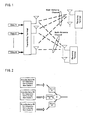
- Fig. 1 is a diagram schematically illustrating a MIMO system. As illustrated in Fig. 1 , multi-antenna wireless channels formed by multiple antennas at each of the transmitting terminal and the receiving terminal include spatial information.
- Precoding technology is a major technology for improving a data transmission rate with use of current spatial information, and is also a technology which uses a channel state information pretreatment transmission signal.
- a precoder is substantially a multi-mode beam generator, and matches transmission signals with the channels for the transmitting terminal and the receiving terminal.
- a basic principle of precoding is that a precoder separates transmission signals into multiple layers and causes the multiple layers to be orthogonal to one another so that (i) transmission signals in each layer can obtain a large gain after passing through channels and (ii) independent orthogonality is ensured.
- Orthogonal frequency division multiplexing (OFDM) technology characteristically has a great anti-fading ability and a high efficiency in frequency use, and is thus used in a high-speed data communication in a multipath environment and a fading environment.
- MIMO-OFDM technology which is a combination of MIMO technology and OFDM technology, is recognized as a core technology for next-generation mobile communications systems.
- the 3GPP (3rd Generation Partnership Project) organization which is an international organization in a field of mobile communications technology, has been playing an important role in standardizing the 3G (3rd generation) cellular system.
- the 3GPP organization has been performing a project since a second half of 2004 to design EUTRA (Evolved Universal Terrestrial Radio Access) and EUTRAN (Evolved Universal Terrestrial Radio Access Network).
- This project is commonly called Long Term Evolution (LTE).
- LTE Long Term Evolution
- MIMO-OFDM technology is used for a downlink communication in an LTE system.
- the 3GPP organization held a conference in Shenzhen, China, in April 2008 to discuss standardization of the 4G (4th Generation) cellular system.
- a concept of "Coordinated multi-point (CoMP) transmission/reception” widely attracted attention and gained support.
- a core idea of the concept is that a plurality of base stations simultaneously provide a communication service to a single user or multiple users so as to improve a rate of transmitting data to a user on a cell border.
- it is essential to use a precoding method for a cooperative communication between multiple multi-antenna base stations.
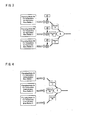
- Fig. 4 illustrates three base stations which employ this cooperative precoding method. This method is advantageous in that it can (i) be performed easily and (ii) reduce an amount of feedback information (see Non Patent Literature 2).
- the above method (1) involves a large amount of signaling information in the precoding by the method involving a dispersion formula.
- This processing method involving a dispersion formula fails to make full use of a characteristic of cooperation between base stations, and there is still room for improvement in performance.
- the method (2) requires a complex operation in actuality and an extra amount of feedback information to check the weight values d 1 , d 2 , ⁇ , d N .
- the method (3) produces a poor performance.
- each of the methods (1) and (2) which employ the distribution precoding method and can thus produce good performances, involves a complex precoding process and a large amount of feedback information.
- the method (3) which is the simplest of the three, produces a poor performance.
- the present invention is based on the method (3) and has improvements over it. It is an object of the present invention to provide a precoding method for a cooperative communication between multiple multi-antenna base stations for a downlink communication which method (i) is easy to perform and (iii) produces an improved performance without largely increasing complexity.
- a serving base station and cooperative communication base stations employ an identical precoding matrix so as to each weight the precoding matrix and then transmit transmission signals. This improves a precoding function in a cooperative communication between multiple multi-antenna base stations.
- the weighting stands for multiplication of results of overall precoding or each layer precoding process by weight values at the serving base station and the cooperative communication base stations.
- a user device corresponding to the serving base station and the cooperative communication base stations receives a signal which is obtained by an operation in which the serving base station and the cooperative communication base stations perform an identical precoding process and additively combine results of overall precoding or each layer precoding process with one another.
- the user device feeds back information which includes (i) precoding matrix information for the serving base station and the cooperative communication base stations, (ii) weight vector information for either overall precoding or layer precoding, and (iii) a quantized value of channel quality.
- This feedback information is thus advantageous in that its signaling information amount is small.
- the serving base station share an identical cell number with the cooperative communication base stations. As such, in a case where an additively combined signal received by the user device is used, it is possible to obtain a larger gain of coherent composition.
- a precoding method of the present invention is for use in a wireless communications system including (i) at least one user device, (ii) a serving base station for providing a service to the at least one user device, and (iii) at least one cooperative communication base station, the precoding method including the steps of: (A) the at least one user device estimating channel state information about downlink channels extending from the serving base station and the at least one cooperative communication base station to the at least one user device, the channel state information including at least (i) precoding matrix information, (ii) weight vector information for overall precoding, and (iii) a quantized value of channel quality; (B) the at least one user device feeding back the estimated channel state information to the serving base station; (C) the serving base station (i) performs resource scheduling according to the channel state information obtained from the at least one user device and (ii) notifying the at least one cooperative communication base station of at least a result of the resource scheduling, the precoding matrix information, and the weight vector information for overall pre
- a precoding method of the present invention is for use in a wireless communications system including (i) at least one user device, (ii) a serving base station for providing a service to the at least one user device, and (iii) at least one cooperative communication base station, the precoding method including the steps of: (A) the at least one user device estimating channel state information about downlink channels extending from the serving base station and the at least one cooperative communication base station to the at least one user device, the channel state information including at least (i) precoding matrix information, (ii) weight vector information for overall precoding, and (iii) a quantized value of channel quality; (B) the at least one user device feeding back the estimated channel state information to the serving base station and the at least one cooperative communication base station; (C) the serving base station (i) performs resource scheduling according to the channel state information obtained from the at least one user device and (ii) notifying the at least one cooperative communication base station of at least a result of the resource scheduling; and (D) the
- a precoding method of the present invention is for use in a wireless communications system including (i) at least one user device, (ii) a serving base station for providing a service to the at least one user device, and (iii) at least one cooperative communication base station, the precoding method including the steps of: (A) the at least one user device estimating channel state information about downlink channels extending from the serving base station and the at least one cooperative communication base station to the at least one user device, the channel state information including at least (i) precoding matrix information, (ii) weight vector information for layer precoding, and (iii) a quantized value of channel quality; (B) the at least one user device feeding back the estimated channel state information to the serving base station; (C) the serving base station (i) performs resource scheduling according to the channel state information obtained from the at least one user device and (ii) notifying the at least one cooperative communication base station of at least a result of the resource scheduling, the precoding matrix information, and the weight vector information for layer pre
- a precoding method of the present invention is for use in a wireless communications system including (i) at least one user device, (ii) a serving base station for providing a service to the at least one user device, and (iii) at least one cooperative communication base station, the precoding method including the steps of: (A) the at least one user device estimating channel state information about downlink channels extending from the serving base station and the at least one cooperative communication base station to the at least one user device, the channel state information including at least (i) precoding matrix information, (ii) weight vector information for layer precoding, and (iii) a quantized value of channel quality; (B) the at least one user device feeding back the estimated channel state information to the serving base station and the at least one cooperative communication base station; (C) the serving base station (i) performs resource scheduling according to the quantized value included in the channel state information obtained from the at least one user device and (ii) notifying the at least one cooperative communication base station of at least a result of the resource scheduling
- the configuration information preferably includes at least (i) cell number(s) of the at least one cooperative communication base station, (ii) a downlink data transmission method, and (iii) antenna configuration(s) of each of the serving base station and the at least one cooperative communication base station.
- the step (A) includes estimating, in a predetermined precoding method, channel state information about the downlink channels extending from the serving base station and the at least one cooperative communication base station to the at least one user device; and the step (D) includes the serving base station and the at least one cooperative communication base station (i) performing, in the predetermined precoding method, precoding with respect to communication data on a basis of an identical precoding matrix and then (ii) each weighting a result of the precoding with a corresponding weight value.
- the weight vector information for layer precoding includes a linear phase increasing sequence; and the weight vector information is an index number for indicating each of elements in the linear phase increasing sequence.
- the precoding matrix information preferably is a code word in a precoding matrix codebook which code word indicates a precoding matrix.
- the precoding matrix codebook is a high-dimensional precoding matrix
- the method further including the step of: truncating the precoding matrix codebook so as to define a low-dimensional precoding matrix codebook.
- the serving base station and the at least one cooperative communication base station preferably perform scrambling with respect to communication data using an identical cell scrambling sequence.
- the cell scrambling sequence is preferably a cell scrambling sequence of the serving base station.
- a wireless communications system of the present invention includes: at least one user device; a serving base station for providing a service to the at least one user device; and at least one cooperative communication base station, the at least one user device (i) estimating channel state information about downlink channels extending from the serving base station and the at least one cooperative communication base station to the at least one user device, the channel state information including at least precoding matrix information, weight vector information for overall precoding, and a quantized value of channel quality, and (ii) feeding back the estimated channel state information to the serving base station, the serving base station (i) performs resource scheduling according to the channel state information obtained from the at least one user device and (ii) notifying the at least one cooperative communication base station of at least a result of the resource scheduling, the precoding matrix information, and the weight vector information for overall precoding, the serving base station and the at least one cooperative communication base station (i) performing precoding with respect to communication data using an identical precoding matrix in correspondence with the precoding matrix information and (ii) each weighting
- a wireless communications system of the present invention includes: at least one user device; a serving base station for providing a service to the at least one user device; and at least one cooperative communication base station, the at least one user device (i) estimating channel state information about downlink channels extending from the serving base station and the at least one cooperative communication base station to the at least one user device, the channel state information including at least precoding matrix information, weight vector information for layer precoding, and a quantized value of channel quality, and (ii) feeding back the estimated channel state information to the serving base station and the at least one cooperative communication base station, the serving base station (i) performs resource scheduling according to the channel state information obtained from the at least one user device and (ii) notifying the at least one cooperative communication base station of at least a result of the resource scheduling, the serving base station and the at least one cooperative communication base station (i) performing precoding with respect to communication data using an identical precoding matrix in correspondence with the precoding matrix information and (ii) each weighting a result of the precoding
- a wireless communications system of the present invention includes: at least one user device; a serving base station for providing a service to the at least one user device; and at least one cooperative communication base station, the at least one user device estimating channel state information about downlink channels extending from the serving base station and the at least one cooperative communication base station to the at least one user device, the channel state information including at least precoding matrix information, weight vector information for layer precoding, and a quantized value of channel quality, and feeding back the estimated channel state information to the serving base station, the serving base station (i) performs resource scheduling according to the channel state information obtained from the at least one user device and (ii) notifying to the at least one cooperative communication base station of at least a result of the resource scheduling, the precoding matrix information, and the weight vector information for layer precoding, the serving base station and the at least one cooperative communication base station (i) performing precoding with respect to communication data using an identical precoding matrix in correspondence with the precoding matrix information and (ii) each weighting a result of the pre
- a wireless communications system of the present invention includes: at least one user device; a serving base station for providing a service to the at least one user device; and at least one cooperative communication base station, the at least one user device (i) estimating channel state information about downlink channels extending from the serving base station and the at least one cooperative communication base station to the at least one user device, the channel state information including at least precoding matrix information, weight vector information for layer precoding, and a quantized value of channel quality, and (ii) feeding back the estimated channel state information to the serving base station and the at least one cooperative communication base station, the serving base station (i) performs resource scheduling according to the channel state information obtained from the at least one user device and (ii) notifying the at least one cooperative communication base station of at least a result of the resource scheduling, the serving base station and the at least one cooperative communication base station (i) performing precoding with respect to communication data using an identical precoding matrix in correspondence with the precoding matrix information and (ii) each weighting a result of the precoding
- the precoding method and the wireless communications system of the present invention for a cooperative communication between multiple multi-antenna base stations for a downlink communication is advantageous in that it can be performed easily and produce a good performance.
- the description below deals with a specific embodiment in which the present invention is applied to an LTE cellular communications system.
- the present invention is, however, not at all limited to the embodiment below, and is thus also applicable to any other communications system such as a future LTE-Advanced system.
- Fig. 5 is a diagram schematically illustrating a multi-cell cellular communications system.
- the cellular system divides a service coverage area into individual wireless coverage areas (that is, cells) adjacent to one another.
- the cells are each in a shape of a regular hexagon in Fig. 5 .
- the cells 100 through 104 joined together constitute the entire service area.
- the cellular communications system further includes base stations 200 through 204 in association with the cells 100 through 104, respectively.
- the base stations 200 through 204 each include at least one transmitter, at least one receiver, and at least one base station control unit as is publicly known in this technical field.
- the base stations are each a service node in a corresponding cell.
- the base stations can each be (i) an independent base station having a function of scheduling wireless resources or (ii) a node dependent on an independent base station which node is, for example, a transmission node or a relay node (normally provided so as to expand a coverage area of a corresponding cell).
- Each of the base stations 200 through 204 is provided in an area of one of the cells 100 through 104, and includes an omnidirectional antenna (see Fig. 5 ).
- the cellular communications system can alternatively have a cell distribution in which at least one directivity antenna is (i) provided for a group of the base stations 200 through 204 and (ii) given a directivity so as to cover a partial area (normally referred to as "sector region") of the cells 100 through 104.
- the multi-cell cellular communications system illustrated in Fig. 5 merely serves to describe the present invention. The cellular system of the present invention thus should not be limited in implementation to the above specific conditions.
- the base stations 200 through 204 can communicate with one another via X2 interfaces 300 through 304 through a wireless or cable link.
- a structure of a three-layer node network including base stations, a wireless network control unit, and a core network is simplified into a two-layer node structure.
- the functions of the Radio Network Control is assigned to the base stations, and the base stations cooperate and communicate with one another via "X2" cable interfaces through a wireless or cable link.
- the cells 100 through 104 contain a plurality of user devices (mobile stations) 400 through 430 distributed throughout.
- the user devices 400 through 430 each include at least one transmitter, at least one receiver, and at least one mobile station control unit as is publicly known in this technical field.
- the user devices 400 through 430 each access the cellular communications system via a serving base station (that is, one of the base stations 200 through 204) which provides a service to the user device.
- a serving base station that is, one of the base stations 200 through 204 which provides a service to the user device.
- each user device theoretically or/and physically belongs to a single serving base station.
- Fig. 5 illustrates only 16 user devices provided, the number of user devices provided in actuality is extremely large.
- the user devices in Fig. 5 are thus merely schematically illustrated for a description of the present invention.
- the user devices 400 through 430 each access the cellular communication network via one of the base stations 200 through 204 which one provides a service to the user device.
- a base station which provides a communication service directly to a user device is referred to as a serving base station for the user device
- any other base station is referred to as a non-serving base station or a cooperative communication base station for the user device.
- the non-serving base station can function as a cooperative communication base station for the serving base station and provide a communication service to the user device together with the serving base station.
- the LTE system of the present embodiment is configured specifically in reference to the 3GPP organization's document TS 36.213 V8.3.0, "Evolved Universal Terrestrial Radio Access (E-UTRA) ; Physical Layer Procedures.”
- the document defines seven downlink data transmission methods: single-antenna transmission; transmission diversity; open-loop space-division multiplexing; closed-loop space-division multiplexing; multiple-user MIMO; closed-loop single-layer precoding; and beam-forming transmission.
- single-antenna transmission is a method for transmitting signals with use of a single antenna, and is an exception for a MIMO system. This method allows transmission of only single-layer data.
- Transmission diversity is a method for transmitting signals in a MIMO system with use of a diversity effect of time and/or frequency. This method improves quality of received signals.
- Open-loop space-division multiplexing is space-division multiplexing which requires no feedback on channel state information from a user device.
- Closed-loop space-division multiplexing is space-division multiplexing which does require feedback on channel state information from a user device.
- Multiple-user MIMO is a method by which multiple users are involved in a downlink communication in a MIMO system at an identical time and at an identical frequency.
- Closed-loop single-layer precoding is a method which uses a MIMO system and which employs precoding technology. This method allows transmission of only single-layer data.
- Beam-forming transmission is a method which uses a MIMO system and which employs beam-forming technology. This method allows transmission of only single-layer data.
- closed-loop space-division multiplexing In of the above seven downlink data transmission methods, closed-loop space-division multiplexing, multiple-user MIMO, and closed-loop single-layer precoding belong to precoding technology.
- the method of the present invention is thus applicable to the three methods out of the seven methods.
- the above applications are each merely an embodiment of the present invention.
- the present invention is thus not limited in application to the three methods.
- the user device 416 is provided with two receive antennas, and is set so as to operate in a mode for a cooperative communication between multiple multi-antenna base stations for a downlink communication.
- the base station 202 is set as a serving base station, whereas the base stations 200 and 204 are each set as a cooperative communication base station.
- the base stations 200, 202, and 204 are each provided with four transmit antennas.
- the serving base station and the cooperative communication base stations for the user device 416 all employ an identical downlink data transmission method, specifically, closed-loop space-division multiplexing.
- the serving base station and the cooperative communication base stations each perform (i) overall precoding with respect to transmission data on the basis of an identical precoding matrix and (ii) weighting with respect to the transmission data so as to transmit the data.
- the weighting stands for multiplication of results of overall precoding by weight values (weight coefficients).
- Overall precoding stands for an operation in which transmission data which (i) is to be transmitted to a user device, (ii) has a plurality of transmission layers, and (iii) is to be multiplied by a precoding matrix is multiplied in its entirety by a precoding matrix without being divided into separate transmission data transmission layers (series or layers of transmission information).
- the results of overall precoding stand for transmission signals generated from overall precoding of the transmission data.
- the user device 416 receives a signal which is obtained by combining (adding at ends of the respective antennas) respective transmission signals transmitted by the serving base station and the cooperative communication base stations.
- the user device feeds back information which includes (i) precoding matrix information for the serving base station and the cooperative communication base stations (for example, a precoding matrix information index number), (ii) weight vector information for overall precoding, and (iii) a quantized value of channel quality.
- the weight vector information for overall precoding stands for vector information (for example, a weight vector information index number) indicative of a weight coefficient corresponding to one of the above base stations.
- the quantized value of channel quality stands for a discretized value indicative of a state (quality) of downlink channels between (i) the user device and (ii) the serving base station and the cooperative communication base stations.
- the user device 416 is provided with two receive antennas, and is set so as to operate in a mode for a cooperative downlink communication between multiple multi-antenna base stations.
- the base station 202 is set as a serving base station, whereas the base stations 200 and 204 are each set as a cooperative communication base station.
- the base stations 200, 202, and 204 are each provided with four transmit antennas.
- the serving base station and the cooperative communication base stations for the user device 416 all employ an identical downlink data transmission method, specifically, closed-loop space-division multiplexing.
- the serving base station and the cooperative communication base stations each perform (i) division of transmission data into a plurality of transmission layers, (ii) layer precoding for each transmission data transmission layer on the basis of an identical precoding matrix, and (iii) weighting with respect to each transmission layer so as to transmit the transmission data.
- the weighting stands for multiplication of results of layer precoding by weight values (weight coefficients).
- Layer precoding stands for an operation in which transmission data which (i) is to be transmitted to a user device and (ii) has a plurality of transmission layers is divided into separate transmission layers (series or layers of transmission information), each of which is then multiplied by a layer precoding matrix corresponding to the transmission data transmission layer.
- the results of layer precoding stand for transmission signals generated from layer precoding of each transmission data transmission layer.
- the user device 416 receives a signal which is obtained by combining (adding at ends of the respective antennas) respective transmission signals transmitted by the serving base station and the cooperative communication base stations.
- the user device feeds back information which includes (i) precoding matrix information (for example, a precoding matrix information index number) for the serving base station and the cooperative communication base stations, (ii) weight vector information for layer precoding, and (iii) a quantized value of channel quality.
- the weight vector information for layer precoding stands for information (for example, a weight vector information index number) indicative of a weight value by which one of the precoded transmission layers is multiplied.
- the quantized value of channel quality stands for a discretized value indicative of a state (quality) of downlink channels between (i) the user device and (ii) the serving base station and the cooperative communication base stations.
- the user device 416 is provided with two receive antennas, and is set so as to operate in a mode for a cooperative downlink communication between multiple multi-antenna base stations.
- the base station 202 is set as a serving base station, whereas the base stations 200 and 204 are each set as a cooperative communication base station.
- the base stations 200 and 202 are each provided with four transmit antennas, whereas the base station 204 is provided with two transmit antennas.
- the serving base station and the cooperative communication base stations for the user device 416 all employ an identical downlink data transmission method, specifically, closed-loop space-division multiplexing.
- the serving base station and the cooperative communication base stations each perform (i) division of transmission data into a plurality of transmission layers, (ii) layer precoding for each transmission data transmission layer on the basis of an identical precoding matrix, and (iii) weighting with respect to each transmission layer so as to transmit the transmission data.
- the weighting stands for multiplication of results of each layer precoding process (that is, each precoded transmission data transmission layer) by weight values.
- the user device 416 receives a signal which is obtained by combining (adding at ends of the respective antennas) respective transmission signals transmitted by the serving base station and the cooperative communication base stations.
- the user device feeds back information which includes (i) precoding matrix information for the serving base station and the cooperative communication base stations, (ii) weight vector information for layer precoding, and (iii) a quantized value of channel quality.
- the weight vector information for layer precoding stands for information indicative of a weight value by which one of the precoded transmission layers is multiplied.
- the user device 416 is provided with two receive antennas, and is set so as to operate in a mode for a cooperative downlink communication between multiple multi-antenna base stations.
- the base station 202 is set as a serving base station, whereas the base stations 200 and 204 are each set as a cooperative communication base station.
- the base stations 200 and 202 are each provided with four transmit antennas, whereas the base station 204 is provided with two transmit antennas.
- the serving base station and the cooperative communication base stations for the user device 416 all employ an identical downlink data transmission method, specifically, closed-loop space-division multiplexing.
- the serving base station and the cooperative communication base stations each perform (i) layer precoding for each transmission data transmission layer on the basis of an identical precoding matrix and (ii) weighting with respect to each transmission layer so as to transmit the transmission data.
- the weighting stands for multiplication of results of overall precoding by weight values.
- the user device 416 receives a signal which is obtained by combining (adding at ends of the respective antennas) transmission signals transmitted by the serving base station and the cooperative communication base stations.
- the user device feeds back information which includes (i) precoding matrix information (for example, a precoding matrix information index number) for the serving base station and the cooperative communication base stations, (ii) weight vector information for overall precoding, and (iii) a quantized value of channel quality.
- the weight vector information for overall precoding stands for an item of vector information (for example, a weight vector information index number) indicative of (i) a weight coefficient corresponding to one of the above base stations and (ii) a weight value by which one of a plurality of overall precoded transmission data sets is multiplied.
- vector information for example, a weight vector information index number
- the user device feeds back information as described in the 3GPP organization's document TS 36.211 V8.3.0, "Evolved Universal Terrestrial Radio Access (E-UTRA); Physical Channels and Modulation .”
- This document defines on pages 51 and 52 precoding matrix information (precoding matrix information index numbers) based on a codebook.
- precoding matrix information precoding matrix information index numbers
- a basic idea is as follows: Space is divided on the basis of code words (predetermined matrices). A channel is then approximated with use of the code words so as to be similar to an actual channel. A code word which allows the channel to be the most similar to the actual channel provides a quantization matrix for the actual channel, and an index number of the code word serves as a quantized value of the actual channel.
- the user device determines channel information and feeds it back to a corresponding base station.
- a base station provided with four transmit antennas transmits data having four layers at a maximum, namely the first to fourth layers, each of which contains 16 code words (index numbers 0 through 15) to be selected from by a user device.
- a base station provided with two transmit antennas transmits data having two layers at a maximum, namely the first and second layers, each of which contains four code words (index numbers 0 through 3) to be selected from by a user device.
- the weight vector information for either overall precoding or layer precoding is a concept which an LTE system lacks. As such, it is necessary to set a codebook corresponding to the weight vector information.
- the embodiment of the present invention while taking into consideration a linear phase increasing sequence, defines a codebook which indicates eight code words as weight vectors for either overall precoding or layer precoding as shown in Table 1 (where N represents a total number of a serving base station and cooperative communication base stations).
- the index numbers of the code words (“Numbers of code words" in Table 1) each represent a result of quantization (corresponding to the above-described quantized value of channel quality) of a weight vector for either overall precoding or layer precoding. The index numbers are fed back by a user device to a corresponding base station.
- the present invention is thus not necessarily performed under the above limitative conditions.
- the above cases of the embodiment are each mainly described from a standpoint of the user device 416. This, however, does not mean that the present invention can be performed only in an application involving a single user device.
- the present invention is in practice applicable also to a case involving multiple user devices. Any user device such as the user devices 408, 410, and 430 in Fig.
- the above cases of the embodiment each involve one serving base station and two cooperative communication base stations.
- the present invention is, however, not necessarily limited to such a condition.
- the present invention is in practice not limited in the number of serving base stations or cooperative communication base stations.
- Fig. 6 is a flowchart illustrating a method of the embodiment of the present invention for a cooperative communication between multiple multi-antenna base stations for a downlink communication in a cellular system.
- the method includes steps 500, 505, 510, and 515.
- a serving base station configures a user device.
- the user device estimates, by the precoding method for a cooperative communication between multiple multi-antenna base stations, channel state information including at least (i) precoding matrix information, (ii) weight vector information for either overall precoding or layer precoding, and (iii) a quantized value of channel quality.
- the user device feeds back channel state information including at least (i) precoding matrix information, (ii) weight vector information for either overall precoding or layer precoding, and (iii) a quantized value of channel quality.
- the serving base station obtains the channel state information about downlink channels extending from the serving base station and cooperative communication base stations to the user device, (ii) performs resource scheduling according to the quantized value of channel quality (for example, selects a channel whose quantized value of channel quality is large), and (iii) transmits, to the cooperative communication base stations by a background communication (for example, via X2 interfaces), a result of the resource scheduling, communication data, the precoding matrix information, and the weight vector information for precoding. Then, later during the step 515, the serving base station and the cooperative communication base stations simultaneously transmit downlink data signals to the user device.
- a background communication for example, via X2 interfaces
- a serving base station configures a user device. Specifically, a serving base station associates a user device with each of the serving base station and cooperative communication base stations. Downlink communication data for a cooperative communication between base stations is transmitted to the user device. The serving base station then generates configuration information indicative of the association. How the serving base station associates the user device with at least one cooperative communication base station is not particularly limited. For example, the serving base station can (i) select, from among cells that are adjacent to a cell to which the serving base station belongs, a predetermined number of cells in order of proximity to the user device, and (ii) designate, as cooperative communication base stations, base stations provided in respective cells thus selected.
- the configuration information preferably includes at least (i) cell numbers for the respective cooperative communication base stations, (ii) a method for transmitting downlink data, and (iii) configuration of antennas at each of the serving base station and the cooperative communication base stations.
- the cell numbers for the respective cooperative communication base stations and the method for transmitting downlink data are normally communicated from the serving base station to the user device by downlink control signaling, and the antenna configuration is communicated to the user device through broadcast channels of the respective base stations (that is, the serving base station and the cooperative communication base stations).
- the antenna configuration stands for the number of transmit antennas provided for the serving base station and the cooperative communication base stations.
- step 500 is performed as in the following three example applications:
- the serving base station for the user device 416 is the base station 202, and the cooperative communication base stations for the user device 416 are the base stations 200 and 204.
- the base stations 200, 202, and 204 communicate information about antenna configuration to the user device through their respective broadcast channels.
- the base stations 200, 202, and 204 are each provided with four transmit antennas as its antenna configuration.
- the serving base station 202 transmits, to the user device 416 by downlink control signaling, information indicative of (i) the cell numbers for the respective cooperative communication base stations 200 and 204 and (ii) a downlink data transmission method (closed-loop space-division multiplexing in this application).
- the serving base station for the user device 416 is the base station 202, and the cooperative communication base stations for the user device 416 are the base stations 200 and 204.
- the base station 202 communicates information about its antenna configuration to the user device through a broadcast channel.
- the base station 202 is provided with four transmit antennas as its antenna configuration.
- the serving base station 202 transmits, to the user device 416 by downlink control signaling, information indicative of (i) the cell numbers for the respective cooperative communication base stations 200 and 204, (ii) the antenna configuration (four transmit antennas), and (iii) a downlink data transmission method (closed-loop space-division multiplexing in this application).
- the serving base station for the user device 416 is the base station 202, and the cooperative communication base stations for the user device 416 are the base stations 200 and 204.
- the base stations 200 and 202 communicate information about antenna configuration to the user device through their respective broadcast channels.
- the base stations 200 and 202 are each provided with four transmit antennas as its antenna configuration.
- the base station 204 through its broadcast channel, communicates information about its antenna configuration to the user device.
- the base station 204 is provided with two transmit antennas as its antenna configuration.
- the serving base station 202 transmits, to the user device 416 by downlink control signaling, information indicative of (i) the cell numbers for the respective cooperative communication base stations 200 and 204 and (ii) a downlink data transmission method (closed-loop space-division multiplexing in this application).
- the above example applications are, as described above, each merely an example of a serving base station locating a user device in accordance with the present invention.
- the example applications thus do not serve to limit the configuration information of a serving base station of the present invention to the above form described in the example applications.
- the user device estimates channel state information by the precoding method for a cooperative communication between multiple multi-antenna base stations.
- the channel state information includes at least (i) precoding matrix information, (ii) weight vector information for either overall precoding or layer precoding, and (iii) a quantized value of channel quality.
- the user device can, after obtaining system information about the serving base station and the cooperative communication base stations, detect downlink reference signals from the serving base station and the cooperative communication base stations. As such, the user device can obtain channel state information about the serving base station and the cooperative communication base stations, and thus estimate channel state information.
- the serving base station and the cooperative communication base stations employ an identical precoding matrix so as to weight transmission signals and then transmit them.
- the serving base station and the cooperative communication base stations preferably perform the weighting by multiplying results of overall precoding by weight values.
- the serving base station and the cooperative communication base stations employ an identical precoding matrix so as to weight transmission signals and then transmit them.
- the serving base station and the cooperative communication base stations preferably perform the weighting by multiplying results of layer precoding by weight values.
- step 505 is described with reference to four example applications below.
- the user device 416 is provided with two receive antennas
- the serving base station for the user device 416 is the base station 202
- the cooperative communication base stations for the user device 416 are the base stations 200 and 204.
- the base stations 200, 202, and 204 are each provided with four transmit antennas.
- H 202 represents a matrix of channels (2 ⁇ 4 matrix; a first dimension of the channel matrix corresponds to the number of receive antennas, and a second dimension of the channel matrix corresponds to the number of transmit antennas) extending from the serving base station 202 to the user device 416
- H 200 and H 204 represent respective matrices of channels (2 ⁇ 4 matrices) extending from the cooperative communication base stations 200 and 204 to the user device 416.
- the precoding matrix is 4 ⁇ 2 in dimension (where the first dimension of the precoding matrix represents the number of transmit antennas, and the second dimension of the precoding matrix represents the number of transmission layers).
- a precoding matrix codebook contains a total of 16 code words, which are set as W 0 , W 1 , ..., W 15 .
- the serving base station 202 and the cooperative communication base stations 200 and 204 employ an identical precoding matrix so as to weight transmission signals and then transmit them.
- the user device 416 receives signals which are obtained as a result of an operation in which the serving base station 202 and the cooperative communication base stations 200 and 204 perform identical overall precoding and additively combine results of an overall precoding process with one another.
- Fig. 7 illustrates an example of how this operation is performed.
- the matrices of channels extending from the serving base station 202 and the cooperative communication base stations 200 and 204 to the user device 416 provide virtual channels through Di additive combinations. Further, the virtual channels are matched with the identical precoding matrix W.
- H i U i H ⁇ ⁇ i ⁇ V i
- a i eigenvalue matrix of H i (2 ⁇ 4 general diagonal matrix)
- V i right singular matrix of H i (4 ⁇ 4 unitary matrix)
- the user device 416 finds a sum of squares of diagonal modes for A i to determine an electric power gain G i for H i .
- the user device 416 After determining the index number x, the user device 416 obtains a virtual channel H x , and selects a suitable precoding matrix W h from W 0 , W 1 , ..., W 15 so as to match it with Hx.
- ⁇ ⁇ ⁇ 2 stands for a square of a mode in a matrix, and indicates an electric power gain obtained for Hx as an amount of electric power after a precoding process.
- quant ⁇ stands for a quantization process.
- a quantized value Q ⁇ of Q can alternatively be expressed as a quantized value of channel quality.
- the estimation of channel information by a user device includes at least finding one precoding matrix index number h , one precoding weight vector index number x , and one quantized value Q ⁇ of channel quality.
- the index number x is obtained from Formula (1)
- the index number h and the quantized value Q ⁇ of channel quality are obtained from Formulae (2) and (3), respectively
- the precoding weight vector codebook ⁇ D i ⁇ of and the precoding matrix codebook ⁇ W j ⁇ are obtained.
- the precoding weight vector codebook ⁇ D i ⁇ and the precoding matrix codebook ⁇ W j ⁇ can each have a design other than the above example. Such design variation does not influence the feasibility of the present invention.
- the index number x , the index number h , and the quantized value Q ⁇ of channel quality can alternatively be obtained by a combined estimating method as in the following Formula (4):
- x h argmax x
- i 0 , 1 , ... , 7 h
- j 0 , 1 , ... , 15 ⁇ H i ⁇ W j ⁇ 2
- the user device 416 is provided with two receive antennas
- the serving base station for the user device 416 is the base station 202
- the cooperative communication base stations for the user device 416 are the base stations 200 and 204.
- the base stations 200, 202, and 204 are each provided with four transmit antennas.
- H 202 represents a matrix of channels (2 ⁇ 4 matrix; a first dimension of the channel matrix corresponds to the number of receive antennas, and a second dimension of the channel matrix corresponds to the number of transmit antennas) from the serving base station 202 to the user device 416
- H 200 and H 204 represent respective matrices of channels (2 ⁇ 4 matrices) from the cooperative communication base stations 200 and 204 to the user device 416.
- the precoding matrix is 4 ⁇ 2 in dimension (where the first dimension of the precoding matrix represents the number of transmit antennas, and the second dimension of the precoding matrix represents the number of transmission layers).
- a precoding matrix codebook contains a total of 16 code words, which are set as W 0 , W 1 , ..., W 15 .
- the serving base station 202 and the cooperative communication base stations 200 and 204 employ an identical precoding matrix so as to weight transmission signals and then transmit them.
- the user device receives signals which are obtained as a result of an operation in which the serving base station 202 and the cooperative communication base stations 200 and 204 perform an identical precoding process and additively combine results of each layer precoding process with one another.
- Fig. 8 illustrates how this operation is performed.
- this example application employs additive combining for each transmission layer.
- each transmission layer is assigned its particular, independent weight vector D i ( l ) .
- a precoding matrix can be divided into precoding vectors w ( l ) .
- w ( l ) represents an l -th column vector for a precoding matrix W.
- matrices of channels extending from the serving base station 202 and the cooperative communication base station 200 and 203 to the user device 416 are each divided into a plurality of transmission layers so as to provide virtual channels for each layer through D i ( l ) additive combinations. Each layer is thus processed with use of an identical precoding vector w ( l ) .
- i l 0 , 1 , ... , 7 h l
- a sum of squares of a mode indicates, as an amount of electric power, a total electric power gain obtained after a precoding process for each layer with respect to H i l .
- quant ⁇ stands for a quantization process.
- a quantized value Q ⁇ of Q can alternatively be expressed as a quantized value of channel quality.
- the estimation of channel information by a user device includes at least finding one precoding matrix index number h , one precoding weight vector index number x , and one quantized value Q ⁇ of channel quality.
- the index numbers x ( l ) and h are obtained from Formula (5), (ii) the quantized value Q ⁇ of channel quality is obtained from Formula (6), and (iii) the precoding weight vector codebook ⁇ D i ( l ) ⁇ and the precoding matrix codebook ⁇ W j ⁇ are obtained.
- the precoding weight vector codebook ⁇ D i (/) ⁇ and the precoding matrix codebook ⁇ W j ⁇ can each have a design other than the above example. Such design variation does not influence the feasibility of the present invention.
- the index number x ( l ), the index number h , and the quantized value Q ⁇ of channel quality can alternatively be obtained by another method.
- the user device 416 is provided with two receive antennas
- the serving base station for the user device 416 is the base station 202
- the cooperative communication base stations for the user device 416 are the base stations 200 and 204.
- the base stations 200 and 204 are each provided with four transmit antennas, whereas the base station 204 is provided with two transmit antennas.
- H 202 represents a matrix of channels (2 ⁇ 4 matrix; a first dimension of the channel matrix corresponds to the number of receive antennas, and a second dimension of the channel matrix corresponds to the number of transmit antennas) from the serving base station 202 to the user device 416
- H 200 represents a matrix of channels (2 ⁇ 4 matrix) from the cooperative communication base station 200 to the user device 416
- H 204 represents a matrix of channels (2 ⁇ 2 matrix) from the cooperative communication base station 204 to the user device 416.
- the precoding matrices of the base stations 200 and 202 is 4 ⁇ 2 in dimension (where the first dimension of the precoding matrix represents the number of transmit antennas, and the second dimension of the precoding matrix represents the number of transmission layers), whereas the precoding matrix of the base station 204 is 2 ⁇ 2 in dimension.
- a codebook of the precoding matrices of the respective base stations 200 and 202 contains a total of 16 code words, which are set as W 0 , W 1 , ..., W 15 . Further, a codebook for the precoding matrix of the base station 204 contains a total of 4 code words, which are set as U 0 , U 1 , ..., U 3 .
- the codebook for the precoding matrix of the base station 204 is different from the codebook for the precoding matrices of the respective base stations 200 and 202.
- a kind of mapping is defined so that as shown in Table 2 below, the codebook for the precoding matrix of the base station 204 and the codebook for the precoding matrices of the respective base stations 200 and 202 are theoretically identical.
- the codebook mapping shown in Table 2 serves as an example to illustrate feasibility of the present invention.
- the present invention can thus be performed with use of word book mapping other than the above example.
- the word book mapping is in practice performed so as to prevent an unnecessary increase in amount of feedback information by making theoretically identical the word book mapping between the serving base station and the cooperative communication base stations.
- the serving base station 202 and the cooperative communication base stations 200 and 204 employ an identical precoding matrix so as to weight transmission signals and then transmit them.
- the user device receives signals which are obtained as a result of an operation in which the serving base station 202 and the cooperative communication base stations 200 and 204 perform an identical precoding process and additively combine results of each layer precoding process with one another.
- Fig. 8 illustrates how this operation is performed.
- this example application employs additive combining for each transmission layer.
- each layer is assigned its particular, independent weight vector D i ( l ) .
- a precoding matrix can be divided into precoding vectors w ( l ) .
- w ( l ) represents an l- th column vector for a precoding matrix W.
- matrices of channels extending from the serving base station 202 and the cooperative communication base station 200 and 203 to the user device are each divided into a plurality of transmission layers so as to provide virtual channels for each layer through D i ( l ) additive combinations.
- Each layer is thus processed with use of an identical precoding vector w ( l ) .
- H 204 is different from H 200 and H 202 in dimension, it is impossible to express virtual channels of each layer by a numerical formula.
- the user device 416 can obtain an index number x ( l ) for a suitable weight vector D x ( l ) and an index number h for a suitable precoding matrix W h as shown in the following Formula (7):
- x l , h argmax x l
- i l 0 , 1 , ... , 7 h l
- a sum of squares of a mode indicates, as an amount of electric power, a total electric power gain obtained after a precoding process for each layer with respect to H i l .
- quant ⁇ stands for a quantization process.
- a quantized value Q of Q can alternatively be expressed as a quantized value of channel quality.
- the estimation of channel information by a user device includes at least finding one precoding matrix index number h , one precoding weight vector index number x , and one quantized value Q ⁇ of channel quality.
- the index numbers x ( l ) and h are obtained from Formula (7)
- the quantized value Q ⁇ of channel quality is obtained from Formula (8)
- the precoding weight vector codebook ⁇ D i (/) ⁇ and the precoding matrix codebook ⁇ W j ⁇ are obtained.
- the precoding weight vector codebook ⁇ D i ( l ) ⁇ and the precoding matrix codebook ⁇ W j ⁇ can each have a design other than the above example. Such design variation does not influence the feasibility of the present invention.
- the index number x ( l ), the index number h , and the quantized value Q ⁇ of channel quality can alternatively be obtained by another method.
- the user device 416 is provided with two receive antennas
- the serving base station for the user device 416 is the base station 202
- the cooperative communication base stations for the user device 416 are the base stations 200 and 204.
- the base stations 200 and 204 are each provided with four transmit antennas, whereas the base station 204 is provided with two transmit antennas.
- H 202 represents a matrix of channels (2 ⁇ 4 matrix; a first dimension of the channel matrix corresponds to the number of receive antennas, and a second dimension of the channel matrix corresponds to the number of transmit antennas) from the serving base station 202 to the user device 416
- H 200 represents a matrix of channels (2 ⁇ 4 matrix) from the cooperative communication base station 200 to the user device 416
- H 204 represents a matrix of channels (2 ⁇ 2 matrix) from the cooperative communication base station 204 to the user device 416.
- the precoding matrices of the base stations 200 and 202 is 4 ⁇ 2 in dimension (where the first dimension of the precoding matrix represents the number of transmit antennas, and the second dimension of the precoding matrix represents the number of transmission layers), whereas the precoding matrix of the base station 204 is 2 ⁇ 2 in dimension.
- a codebook of the precoding matrices of the respective base stations 200 and 202 contains a total of 16 code words, which are set as W 0 , W 1 , ..., W 15 . Further, a codebook for the precoding matrix of the base station 204 contains a total of 4 code words, which are set as U 0 , U 1 , ..., U 3 .
- the codebook for the precoding matrix of the base station 204 is different from the codebook for the precoding matrices of the respective base stations 200 and 202.
- a low-dimensional codebook contains truncated codewords from a high-dimensional codebook so that the codebook for the precoding matrix of the base station 204 and the codebook for the precoding matrices of the respective base stations 200 and 202 are theoretically identical.
- tx represents the number of transmit antennas at a base station corresponding to a low-dimensional codebook
- W i tx represents a code word on a first row tx obtained by dividing W i .
- the base station corresponding to a low-dimensional codebook is the base station 204, which is provided with two transmit antennas.
- the precoding codebook for the base station 204 originally contains only four code words. However, truncating a high-dimensional codebook allows the precoding codebook for the base station 204 to contain 16 code words.
- the codebook division shown in Table 3 is naturally a mere example to illustrate feasibility of the present invention. The present invention can thus be performed with use of word book division other than the above example.
- the word book division is in practice performed so as to prevent an unnecessary increase in amount of feedback information by making theoretically identical the word book of the precoding matrices between the serving base station and the cooperative communication base stations.
- the serving base station 202 and the cooperative communication base stations 200 and 204 employ an identical precoding matrix so as to weight transmission signals and then transmit them.
- the user device 416 receives signals which are obtained as a result of an operation in which the serving base station 202 and the cooperative communication base stations 200 and 204 perform an identical precoding process and additively combine results of each layer precoding process with one another.
- Fig. 8 illustrates how this operation is performed.
- this example application employs additive combining for each transmission layer.
- each layer is assigned its particular, independent weight vector D i ( l ) .
- a precoding matrix can be divided into precoding vectors w ( l ) .
- w ( l ) represents an l- th column vector for a precoding matrix W.
- matrices of channels extending from the serving base station 202 and the cooperative communication base station 200 and 203 to the user device are each divided into a plurality of transmission layers so as to provide virtual channels for each layer through D i ( l ) additive combinations.
- Each layer is thus processed with use of an identical precoding vector w ( l ) .
- H 204 is different from H 200 and H 202 in dimension, virtual channels of each layer cannot be expressed by a numerical formula.
- the user device 416 can obtain an index number x ( l ) for a suitable weight vector D x ( l ) and an index number h for a suitable precoding matrix W h as shown in the following Formula (9):
- x l , h argmax x l
- i l 0 , 1 , ... , 7 h l
- a sum of squares of a mode indicates, as an amount of electric power, a total electric power gain obtained after a precoding process for each layer with respect to H i l .
- quant ⁇ stands for a quantization process.
- a quantized value Q ⁇ of Q can alternatively be expressed as a quantized value of channel quality.
- the estimation of channel information by a user device includes at least finding one precoding matrix index number h, one precoding weight vector index number x , and one quantized value Q ⁇ of channel quality.
- the index numbers x(l) and h are obtained from Formula (9)
- the quantized value Q ⁇ of channel quality is obtained from Formula (10)
- the precoding weight vector codebook ⁇ D i ( l ) ⁇ and the precoding matrix codebook ⁇ W j ⁇ are obtained.
- the precoding weight vector codebook ⁇ D i ( l ) ⁇ and the precoding matrix codebook ⁇ W j ⁇ can each have a design other than the above example. Such design variation does not influence the feasibility of the present invention.
- the index number x ( l ) , the index number h, and the quantized value Q ⁇ of channel quality can alternatively be obtained by another method.
- the user device 416 is provided with two receive antennas
- the serving base station for the user device 416 is the base station 202
- the cooperative communication base stations for the user device 416 are the base stations 200 and 204.
- the base stations 200 and 204 are each provided with four transmit antennas, whereas the base station 204 is provided with two transmit antennas.
- H 202 represents a matrix of channels (2 ⁇ 4 matrix; a first dimension of the channel matrix corresponds to the number of receive antennas, and a second dimension of the channel matrix corresponds to the number of transmit antennas) from the serving base station 202 to the user device 416
- H 200 represents a matrix of channels (2 ⁇ 4 matrix) from the cooperative communication base station 200 to the user device 416
- H 204 represents a matrix of channels (2 ⁇ 2 matrix) from the cooperative communication base station 204 to the user device 416.
- the precoding matrices of the base stations 200 and 202 is 4 ⁇ 2 in dimension (where the first dimension of the precoding matrix represents the number of transmit antennas, and the second dimension of the precoding matrix represents the number of transmission layers), whereas the precoding matrix of the base station 204 is 2 ⁇ 2 in dimension.
- a codebook of the precoding matrices of the respective base stations 200 and 202 contains a total of 16 code words, which are set as W 0 , W 1 , ..., W 15 . Further, a codebook for the precoding matrix of the base station 204 contains a total of 4 code words, which are set as U 0 , U 1 , ..., U 3 .
- the codebook for the precoding matrix of the base station 204 is different from the codebook for the precoding matrices of the respective base stations 200 and 202.
- a kind of mapping is defined so that as shown in Table 2 above, the codebook for the precoding matrix of the base station 204 and the codebook for the precoding matrices of the respective base stations 200 and 202 are theoretically identical.
- the above codebooks are mapped as shown in the above Table 2.
- the codebook mapping shown in Table 2 serves as an example to illustrate feasibility of the present invention.
- the present invention can thus be performed with use of word book mapping other than the above example.
- the word book mapping is in practice performed so as to prevent an unnecessary increase in amount of feedback information by making theoretically identical the word book mapping between the serving base station and the cooperative communication base stations.
- the serving base station 202 and the cooperative communication base stations 200 and 204 employ a theoretically identical precoding matrix so as to weight transmission signals and then transmit them.
- the user device 416 receives signals which are obtained as a result of an operation in which the serving base station 202 and the cooperative communication base stations 200 and 204 perform identical precoding and additively combine results of an overall precoding process with one another.
- Fig. 7 illustrates an example of how this operation is performed.
- the matrices of channels extending from the serving base station 202 and the cooperative communication base stations 200 and 204 to the user device provide virtual channels through Di additive combinations. Further, the virtual channels are matched with the identical precoding matrix W.
- W identical precoding matrix employed by a serving base station and cooperative base stations
- H 204 is different from H 200 and H 202 in dimension, virtual channels cannot be expressed by a numerical formula.
- the user device 416 can obtain an index number x for a suitable weight vector D x and an index number h for a suitable precoding matrix W h as shown in the following Formula (11):
- x ⁇ h argmax x
- i 0 , 1 , ... , 7 h
- j 0 , 1 , ... , 15 ⁇ ⁇ P 202 ⁇ H 202 ⁇ d i 202 + P 200 ⁇ H 200 ⁇ d i 200 + P 204 ⁇ H 204 ⁇ d i ⁇ W j ⁇ 2
- Q ⁇ P 202 ⁇ H 202 ⁇ d x 202 + P 200 ⁇ H 200 ⁇ d x 200 + P 204 ⁇ H 204 ⁇ d x ⁇ d x
- ⁇ ⁇ ⁇ 2 stands for a square of a mode in a matrix, and indicates an electric power gain obtained as an amount of electric power after a precoding process.
- the electric power gain can alternatively be expressed as an amount Q indicative of channel quality.
- quant ⁇ stands for a quantization process.
- a quantized value Q ⁇ of Q can alternatively be expressed as a quantized value of channel quality.
- W h corresponding to H 200 and H 202 is a 4 ⁇ 2 matrix
- W h corresponding to H 204 is a 2 ⁇ 2 matrix.
- H 200 , H 200 , and H 204 each provide a 2 ⁇ 2 matrix after being multiplied by W h .
- the addition in Formula (11) can thus be performed.
- the estimation of channel information by a user device includes at least finding one precoding matrix index number h , one precoding weight vector index number x , and one quantized value Q ⁇ of channel quality.
- the index numbers x and h and the quantized value Q ⁇ of channel quality are obtained from Formula (11) and (ii) the precoding weight vector codebook ⁇ D i ⁇ and the precoding matrix codebook ⁇ W j ⁇ are obtained.
- the precoding weight vector codebook ⁇ D i ⁇ and the precoding matrix codebook ⁇ W j ⁇ can each have a design other than the above example. Such design variation does not influence the feasibility of the present invention.
- the index number x(l), the index number h, and the quantized value Q ⁇ of channel quality can alternatively be obtained by another method.
- the user device 416 is provided with two receive antennas
- the serving base station for the user device 416 is the base station 202
- the cooperative communication base stations for the user device 416 are the base stations 200 and 204.
- the base stations 200 and 204 are each provided with four transmit antennas, whereas the base station 204 is provided with two transmit antennas.
- H 202 represents a matrix of channels (2 ⁇ 4 matrix; a first dimension of the channel matrix corresponds to the number of receive antennas, and a second dimension of the channel matrix corresponds to the number of transmit antennas) from the serving base station 202 to the user device 416
- H 200 represents a matrix of channels (2 ⁇ 4 matrix) from the cooperative communication base station 200 to the user device 416
- H 204 represents a matrix of channels (2 ⁇ 2 matrix) from the cooperative communication base station 204 to the user device 416.
- the precoding matrices of the base stations 200 and 202 is 4 ⁇ 2 in dimension (where the first dimension of the precoding matrix represents the number of transmit antennas, and the second dimension of the precoding matrix represents the number of transmission layers), whereas the precoding matrix of the base station 204 is 2 ⁇ 2 in dimension.
- a codebook of the precoding matrices of the respective base stations 200 and 202 contains a total of 16 code words, which are set as W 0 , W 1 , ..., W 15 . Further, a codebook for the precoding matrix of the base station 204 contains a total of 4 code words, which are set as U 0 , U 1 , ..., U 3 .
- the codebook for the precoding matrix of the base station 204 is different from the codebook for the precoding matrices of the respective base stations 200 and 202.
- a high-dimensional codebook is truncated to define a low-dimensional codebook so that the codebook for the precoding matrix of the base station 204 and the codebook for the precoding matrices of the respective base stations 200 and 202 are theoretically identical.
- the above division is shown in the above Table 3.
- tx represents the number of transmit antennas at a base station corresponding to a low-dimensional codebook
- W i tx represents a first row tx obtained by dividing W i .
- the base station corresponding to a low-dimensional codebook is the base station 204, which is provided with two transmit antennas.
- the precoding codebook of the base station 204 originally contains only four code words. However, truncating a high-dimensional codebook allows the precoding codebook of the base station 204 to contain 16 code words.
- the codebook division shown in Table 3 is naturally a mere example to illustrate feasibility of the present invention.
- the present invention can thus be performed with use of word book division other than the above example.
- the word book division is in practice performed so as to prevent an unnecessary increase in amount of feedback information by making theoretically identical the word book of the precoding matrices between the serving base station and the cooperative communication base stations.
- the serving base station 202 and the cooperative communication base stations 200 and 204 employ a theoretically identical precoding matrix so as to weight transmission signals and then transmit them.
- the matrices of channels extending from the serving base station 202 and the cooperative communication base stations 200 and 204 to the user device provide virtual channels through D i additive combinations. Further, the virtual channels are matched with the identical precoding matrix W. This can be expressed by the following numerical formula:
- H 204 is different from H 200 and H 202 in dimension, virtual channels cannot be expressed by a numerical formula.
- the user device 416 can obtain an index number x for a suitable weight vector D x and an index number h for a suitable precoding matrix W h as shown in the following Formula (12):
- x ⁇ h argmax x
- i 0 , 1 , ... , 7 h
- j 0 , 1 , ... , 15 ⁇ ⁇ P 202 ⁇ H 202 ⁇ d i 202 + P 200 ⁇ H 200 ⁇ d i 200 + P 204 ⁇ H 204 ⁇ d i ⁇ W j ⁇ 2
- Q ⁇ P 202 ⁇ H 202 ⁇ d x 202 + P 200 ⁇ H 200 ⁇ d x 200 + P 204 ⁇ H 204 ⁇ d x ⁇ x
- ⁇ ⁇ ⁇ 2 stands for a square of a mode in a matrix, and indicates an electric power gain obtained as an amount of electric power after a precoding process.
- the electric power gain can alternatively be expressed as an amount Q indicative of channel quality.
- quant ⁇ stands for a quantization process.
- a quantized value Q ⁇ of Q can alternatively be expressed as a quantized value of channel quality.
- W h corresponding to H 200 and H 202 is a 4 ⁇ 2 matrix
- W h corresponding to H 204 is a 2 ⁇ 2 matrix.
- H 200 , H 200 , and H 204 each provide a 2 ⁇ 2 matrix after being multiplied by W h .
- the addition in Formula (11) can thus be performed.
- the estimation of channel information by a user device includes at least finding one precoding matrix index number h, one precoding weight vector index number x , and one quantized value Q ⁇ of channel quality.
- the index numbers x and h and the quantized value Q ⁇ of channel quality are obtained from Formula (12) and (ii) the precoding weight vector codebook ⁇ D i ⁇ and the precoding matrix codebook ⁇ W j ⁇ are obtained.
- the precoding weight vector codebook ⁇ D i ⁇ and the precoding matrix codebook ⁇ W j ⁇ can each have a design other than the above example. Such design variation does not influence the feasibility of the present invention.
- the index number x ( l ), the index number h , and the quantized value Q ⁇ of channel quality can alternatively be obtained by another method.
- the example applications described above each merely serve, in accordance with the present invention, as an example of how a user device estimates channel state information.
- the present invention is thus not limited in form of implementation to the above example applications.
- the user device feeds back channel state information which includes at least (i) precoding matrix information, (ii) weight vector information either for overall precoding or for layer precoding, and (iii) a quantized value of channel quality.
- the user device preferably feeds back channel state information for the serving base station and each cooperative communication base station only to the serving base station.
- the user device preferably feeds back channel state information for the serving base station and each cooperative communication base station to each of the serving base station and the cooperative communication base stations.
- step 510 is described with reference to four example applications below.
- the serving base station for the user device 416 is the base station 202, whereas the cooperative communication base stations for the user device 416 are the base stations 200 and 204.
- the serving base station and the cooperative communication base stations for the user device 416 employ an identical downlink data transmission method, specifically, closed-loop space-division multiplexing. As illustrated in Fig. 9 , the user device 416 feeds back downlink channel state information for the serving base station and the cooperative communication base stations only to the serving base station.
- Fig. 9 the user device 416 feeds back downlink channel state information for the serving base station and the cooperative communication base stations only to the serving base station.
- the user device 416 feeds back, only to the serving base station 202 as the channel state information, at least (i) one precoding matrix index number, (ii) one precoding weight vector index number, and (iii) one quantized value of channel quality (as indicated in Fig. 9 by a feedback process 700).
- the serving base station for the user device 416 is the base station 202, whereas the cooperative communication base stations for the user device 416 are the base stations 200 and 204.
- the serving base station and the cooperative communication base stations for the user device 416 employ an identical downlink data transmission method, specifically, closed-loop space-division multiplexing. As illustrated in Fig. 10 , the user device 416 feeds back downlink channel state information for the serving base station and each cooperative communication base station to each of the serving base station and the cooperative communication base stations.
- Fig. 10 the user device 416 feeds back downlink channel state information for the serving base station and each cooperative communication base station to each of the serving base station and the cooperative communication base stations.
- the user device 416 feeds back, to each of the serving base station 202 and the cooperative communication base stations 200 and 204 as the channel state information, at least (i) one preceding matrix index number and (ii) two layer precoding weight vector index numbers (as indicated in Fig. 10 by respective feedback processes 710, 712, and 714).
- the serving base station for the user device 416 is the base station 202, whereas the cooperative communication base stations for the user device 416 are the base stations 200 and 204.
- the serving base station and the cooperative communication base stations for the user device 416 employ an identical downlink data transmission method, specifically, closed-loop space-division multiplexing. As illustrated in Fig. 9 , the user device 416 feeds back downlink channel state information for the serving base station and the cooperative communication base stations only to the serving base station.
- Fig. 9 the user device 416 feeds back downlink channel state information for the serving base station and the cooperative communication base stations only to the serving base station.
- the user device 416 feeds back, only to the serving base station 202 as the channel state information, at least (i) one precoding matrix index number, (ii) two layer precoding weight vector index numbers, and (iii) one quantized value of channel quality (as indicated in Fig. 9 by a feedback process 700).
- the serving base station for the user device 416 is the base station 202, whereas the cooperative communication base stations for the user device 416 are the base stations 200 and 204.
- the serving base station and the cooperative communication base stations for the user device 416 employ an identical downlink data transmission method, specifically, closed-loop space-division multiplexing. As illustrated in Fig. 10 , the user device 416 feeds back downlink channel state information for the serving base station and each cooperative communication base station to each of the serving base station and the cooperative communication base stations.
- Fig. 10 the user device 416 feeds back downlink channel state information for the serving base station and each cooperative communication base station to each of the serving base station and the cooperative communication base stations.
- the user device 416 feeds back, as the channel state information, at least (i) one precoding matrix index number and (ii) one precoding weight vector index number to each of the serving base station 202 and the cooperative communication base stations 200 and 204 (as indicated in Fig. 10 by respective feedback processes 710, 712, and 714).
- the above examples each merely serve to illustrate, in accordance with the present invention, how a user device feeds back channel state information.
- the present invention is naturally not limited to the above examples in terms of how a user device feeds back channel state information.
- the serving base station obtains channel state information about downlink channels from the serving base station and cooperative communication base stations to the user device, (ii) performs resource scheduling according to the quantized value of channel quality (for example, selects a channel whose quantized value of channel quality is large), and (iii) transmits, to the cooperative communication base stations by a background communication, a result of resource scheduling, communication data, the precoding matrix information, and the weight vector information for precoding. Then, later during the step 515, the serving base station and the cooperative communication base stations simultaneously transmit downlink data signals to the user device.
- the serving base station obtains downlink channel state information on the basis of the feedback from the user device, and then performs resource scheduling.
- the serving base station next transmits a result of the resource scheduling and downlink communication data to each of the cooperative communication base stations.
- downlink communication data can be transmitted, instead of by the serving base station, through an upper layer directly to each of the cooperative communication base stations and the serving base station.
- the serving base station can transmit, to each cooperative communication base station, precoding matrix information and precoding weight vector information both determined from the downlink channel state information for the serving base station and the cooperative communication base stations.
- the serving base station and the cooperative communication base stations simultaneously transmit downlink data to the user device, the serving base station and the cooperative communication base stations perform scrambling with respect to communication data on the basis of an identical cell scrambling sequence.
- the identical cell scrambling sequence is, for example, a cell scrambling sequence of the serving base station.
- the cell scrambling serves as data encryption so that an unintended user device will not receive the communication data by mistake.
- the 3GPP organization's document TS 36.211 V8.3.0, "Evolved Universal Terrestrial Radio Access (E-UTRA); Physical Channels and Modulation" defines on page 45 the cell scrambling sequence.
- the cell scrambling sequence is related to a cell number and a user device number.
- step 515 is described with reference to two example applications below.
- the serving base station for the user device 416 is the base station 202, whereas the cooperative communication base stations for the user device 416 are the base stations 200 and 204.
- the serving base station and the cooperative communication base stations for the user device 416 employ an identical downlink data transmission method, specifically, closed-loop space-division multiplexing.
- the cooperative communication base stations 200 and 204 when transmitting downlink data signals, employ a scrambling sequence S 202 for the serving base station 202 so as to reduce complexity of a signal receiving process.
- the serving base station for the user device 416 is the base station 202, whereas the cooperative communication base stations for the user device 416 are the base stations 200 and 204.
- the serving base station and the cooperative communication base stations for the user device 416 employ an identical downlink data transmission method, specifically, closed-loop space-division multiplexing.
- the serving base station 202 and the cooperative communication base stations 200 and 204 when transmitting downlink data signals, employ an identical scrambling sequence S x so as to reduce complexity of a signal receiving process.
- the above examples each merely serve to illustrate, in accordance with the present invention, how the serving base station and the cooperative communication base stations simultaneously transmit downlink data signals to the user device.
- the present invention is naturally not limited to the above examples in terms of how the serving base station and the cooperative communication base stations simultaneously transmit downlink data signals to the user device.
- the present invention is suitably applicable to a wireless communications system in which a cooperative communication is performed between multiple multi-antenna base stations.
Landscapes
- Engineering & Computer Science (AREA)
- Signal Processing (AREA)
- Computer Networks & Wireless Communication (AREA)
- Physics & Mathematics (AREA)
- Mathematical Physics (AREA)
- Power Engineering (AREA)
- Quality & Reliability (AREA)
- Mobile Radio Communication Systems (AREA)
- Radio Transmission System (AREA)
Applications Claiming Priority (2)
| Application Number | Priority Date | Filing Date | Title |
|---|---|---|---|
| CN200810172704.1A CN101729131B (zh) | 2008-11-03 | 2008-11-03 | 无线通信系统及预编码方法 |
| EP09828972.1A EP2352247A4 (fr) | 2008-11-03 | 2009-11-04 | Système de communication sans fil et procédé de précodage |
Related Parent Applications (1)
| Application Number | Title | Priority Date | Filing Date |
|---|---|---|---|
| EP09828972.1A Division EP2352247A4 (fr) | 2008-11-03 | 2009-11-04 | Système de communication sans fil et procédé de précodage |
Publications (1)
| Publication Number | Publication Date |
|---|---|
| EP2887559A1 true EP2887559A1 (fr) | 2015-06-24 |
Family
ID=42225603
Family Applications (2)
| Application Number | Title | Priority Date | Filing Date |
|---|---|---|---|
| EP09828972.1A Withdrawn EP2352247A4 (fr) | 2008-11-03 | 2009-11-04 | Système de communication sans fil et procédé de précodage |
| EP15000309.3A Withdrawn EP2887559A1 (fr) | 2008-11-03 | 2009-11-04 | Système de communication sans fil et procédé de précodage |
Family Applications Before (1)
| Application Number | Title | Priority Date | Filing Date |
|---|---|---|---|
| EP09828972.1A Withdrawn EP2352247A4 (fr) | 2008-11-03 | 2009-11-04 | Système de communication sans fil et procédé de précodage |
Country Status (5)
| Country | Link |
|---|---|
| US (1) | US9325390B2 (fr) |
| EP (2) | EP2352247A4 (fr) |
| JP (1) | JP5406854B2 (fr) |
| CN (1) | CN101729131B (fr) |
| WO (1) | WO2010061724A1 (fr) |
Families Citing this family (39)
| Publication number | Priority date | Publication date | Assignee | Title |
|---|---|---|---|---|
| WO2010075640A1 (fr) * | 2008-12-31 | 2010-07-08 | 上海贝尔股份有限公司 | Procédé de précodage d'unités de station de base multiples, terminal mobile et station de base reposant sur un livre de code |
| US8830918B2 (en) | 2009-03-16 | 2014-09-09 | Interdigital Patent Holdings, Inc. | Method and apparatus for performing uplink transmit diversity |
| CN101854199B (zh) * | 2009-03-31 | 2015-01-14 | 株式会社Ntt都科摩 | 一种无线通信中自适应协作传输的方法、系统和发射机 |
| JP5344046B2 (ja) * | 2009-10-08 | 2013-11-20 | 富士通株式会社 | 無線通信システム及び移動端末並びに協調通信方法 |
| WO2011077260A2 (fr) * | 2009-12-25 | 2011-06-30 | France Telecom | Procédé et système de transmission de signaux de télécommunications |
| JP2011259257A (ja) * | 2010-06-10 | 2011-12-22 | Sharp Corp | 基地局装置、端末装置、通信システム、および、通信方法 |
| CN102948085B (zh) * | 2010-06-18 | 2016-08-24 | 日本电气株式会社 | 针对无线电通信系统中下行链路协同多点传输的预编码技术 |
| CN103081371B (zh) * | 2010-09-03 | 2016-02-03 | 富士通株式会社 | Mimo通信网络中的方法和用户设备、无线通信系统 |
| CN102404800B (zh) * | 2010-09-15 | 2014-07-09 | 华为技术有限公司 | 数据传输处理方法、装置及系统 |
| EP4170937A1 (fr) * | 2010-12-10 | 2023-04-26 | Sun Patent Trust | Procédé de génération de signal et dispositif de génération de signal |
| CN102594517B (zh) * | 2011-01-10 | 2017-12-26 | 中兴通讯股份有限公司 | 上行预编码指示信息下行反馈方法及装置、反馈系统及接收装置 |
| CN102075294B (zh) * | 2011-01-12 | 2018-05-01 | 中兴通讯股份有限公司 | 一种协作预编码方法及系统 |
| EP2665304A4 (fr) * | 2011-01-14 | 2016-08-03 | Fujitsu Ltd | Système de communications mobiles, dispositif de station de base et procédé de commande de communication |
| US8730989B2 (en) * | 2011-02-11 | 2014-05-20 | Interdigital Patent Holdings, Inc. | Method and apparatus for closed loop transmit diversity transmission initial access |
| US9325401B2 (en) * | 2011-05-13 | 2016-04-26 | Fujitsu Limited | Beamforming from multiple transmission sites |
| CN102891739B (zh) * | 2011-07-19 | 2017-10-10 | 中兴通讯股份有限公司 | 一种基于码本的多点协作预编码实现方法和装置 |
| US8797966B2 (en) | 2011-09-23 | 2014-08-05 | Ofinno Technologies, Llc | Channel state information transmission |
| CN103023607B (zh) * | 2011-09-23 | 2017-05-10 | 中兴通讯股份有限公司 | 一种协同传输数据的方法及系统 |
| WO2013051909A2 (fr) * | 2011-10-07 | 2013-04-11 | 엘지전자 주식회사 | Procédé et appareil pour émettre-recevoir des informations d'état du canal dans un système de communication multipoint coopératif |
| WO2013058468A1 (fr) * | 2011-10-16 | 2013-04-25 | 엘지전자 주식회사 | Procédé permettant de transmettre un signal descendant dans un système de communication sans fil coopératif d'une station de base, et appareil associé |
| US8885569B2 (en) | 2011-12-19 | 2014-11-11 | Ofinno Technologies, Llc | Beamforming signaling in a wireless network |
| US9148780B2 (en) * | 2012-03-15 | 2015-09-29 | Lg Electronics Inc. | Method and apparatus for secure data transmission |
| WO2013150387A1 (fr) * | 2012-04-05 | 2013-10-10 | Marvell World Trade Ltd. | Procédé et appareil pour effectuer conjointement une estimation de canal et une estimation de brouillage dans un système de communication sans fil |
| CN103378891B (zh) * | 2012-04-25 | 2017-11-24 | 中兴通讯股份有限公司 | 基于全局预编码的业务传输方法及系统、用户设备及基站 |
| US8913682B2 (en) * | 2012-05-18 | 2014-12-16 | Samsung Electronics Co., Ltd. | Apparatus and method for channel state information codeword construction for a cellular wireless communication system |
| RU2615980C2 (ru) * | 2012-11-09 | 2017-04-12 | ЭлДжи ЭЛЕКТРОНИКС ИНК. | Способ передачи посредством обратной связи информации о состоянии канала в системе беспроводной связи и соответствующее устройство |
| US9780843B2 (en) * | 2012-11-16 | 2017-10-03 | Avago Technologies General Ip (Singapore) Pte. Ltd. | Interference suppression and alignment for cellular networks |
| US20140198868A1 (en) * | 2013-01-17 | 2014-07-17 | Nokia Solutions And Networks Oy | DL MIMO Precoding Enhancement |
| US20140269409A1 (en) * | 2013-03-14 | 2014-09-18 | Telefonaktiebolaget L M Ericsson (Publ) | Explicit signaling of number of receiver antennas |
| EP2996259A4 (fr) * | 2013-05-09 | 2016-07-13 | Fujitsu Ltd | Système de communication , station de base, station mobile et procédé de mesure de qualité de réception |
| US9825676B2 (en) | 2013-08-07 | 2017-11-21 | Nec Corporation | Generating precoders for joint transmission from multiple transmission points to multiple user equipments in a downlink coordinated multipoint transmission/reception communications system |
| US20150043522A1 (en) * | 2013-08-07 | 2015-02-12 | Broadcom Corporation | Enhanced mu-mimo network assisted interference suppression |
| CN105337683B (zh) * | 2014-06-24 | 2018-11-06 | 华为技术有限公司 | 一种针对csi反馈系统的发射加权方法及装置 |
| CN105846950A (zh) * | 2015-01-15 | 2016-08-10 | 中兴通讯股份有限公司 | 相干jt的实现方法和装置 |
| CN107682059A (zh) * | 2016-08-02 | 2018-02-09 | 索尼公司 | 用于网络控制端和中央处理节点的电子设备和方法 |
| US10044423B2 (en) * | 2016-10-20 | 2018-08-07 | Samsung Electronics Co., Ltd | System and method for precoder selection in multiple-input multiple-output (MIMO) systems with discrete fourier transform (DFT)-based codebook |
| CN110838860B (zh) | 2018-08-17 | 2023-06-27 | 大唐移动通信设备有限公司 | 一种信号传输方法、装置、终端及网络侧设备 |
| FR3103337A1 (fr) * | 2019-11-14 | 2021-05-21 | Orange | Procédé de sélection d’au moins un faisceau, station de base pour la mise en œuvre d’un tel procédé |
| CN113541750B (zh) * | 2020-04-17 | 2022-08-19 | 华为技术有限公司 | 协作波束赋形方法、通信装置、通信系统及存储介质 |
Citations (2)
| Publication number | Priority date | Publication date | Assignee | Title |
|---|---|---|---|---|
| WO2008030035A2 (fr) * | 2006-09-05 | 2008-03-13 | Lg Electronics Inc. | Procédé de transmission d'une information en retour pour précodage et procédé de précodage |
| US20080205533A1 (en) * | 2006-09-19 | 2008-08-28 | Lg Electronics Inc. | Method of transmitting using phase shift-based precoding and apparatus for implementing the same in a wireless communication system |
Family Cites Families (11)
| Publication number | Priority date | Publication date | Assignee | Title |
|---|---|---|---|---|
| JP4614798B2 (ja) * | 2005-03-16 | 2011-01-19 | 富士通株式会社 | 移動局および重み付け制御方法 |
| US8068872B2 (en) * | 2005-10-06 | 2011-11-29 | Telefonaktiebolaget Lm Ericsson (Publ) | Signaling support for antenna selection using subset lists and subset masks |
| US20090252113A1 (en) * | 2005-11-21 | 2009-10-08 | Mitsubishi Electric Corporation | Radio Communication System, Base Station, Mobile Device, and Handover Control Server |
| US20080153428A1 (en) * | 2006-12-04 | 2008-06-26 | Samsung Electronics Co., Ltd. | Apparatus and method for transmitting/receiving feedback information in a mobile communication system using array antennas |
| JP4889532B2 (ja) * | 2007-03-20 | 2012-03-07 | 株式会社エヌ・ティ・ティ・ドコモ | 移動通信システムにおける基地局装置及び方法 |
| CN101277172B (zh) * | 2007-03-30 | 2011-04-13 | 华为技术有限公司 | 一种预编码矩阵生成方法、装置和系统 |
| KR101409115B1 (ko) * | 2007-06-08 | 2014-06-17 | 엘지전자 주식회사 | 다중 안테나 시스템에서 가중치 정보 전송 방법 |
| US8374275B2 (en) * | 2007-06-23 | 2013-02-12 | Panasonic Corporation | Method and system for communication channel optimization in a multiple-input multiple-output (MIMO) communication system |
| US8223855B2 (en) * | 2007-08-10 | 2012-07-17 | Motorola Mobility, Inc. | Method for blindly detecting a precoding matrix index |
| KR100995045B1 (ko) | 2007-12-31 | 2010-11-19 | 엘지전자 주식회사 | 협동 다중 입출력 통신 시스템에서, 프리코딩된 신호를송신하는 방법 |
| US8458558B2 (en) * | 2008-04-30 | 2013-06-04 | Motorola Mobility Llc | Multi-antenna configuration signaling in wireless communication system |
-
2008
- 2008-11-03 CN CN200810172704.1A patent/CN101729131B/zh active Active
-
2009
- 2009-11-04 EP EP09828972.1A patent/EP2352247A4/fr not_active Withdrawn
- 2009-11-04 US US13/126,677 patent/US9325390B2/en active Active
- 2009-11-04 EP EP15000309.3A patent/EP2887559A1/fr not_active Withdrawn
- 2009-11-04 WO PCT/JP2009/069146 patent/WO2010061724A1/fr active Application Filing
- 2009-11-04 JP JP2010540438A patent/JP5406854B2/ja active Active
Patent Citations (2)
| Publication number | Priority date | Publication date | Assignee | Title |
|---|---|---|---|---|
| WO2008030035A2 (fr) * | 2006-09-05 | 2008-03-13 | Lg Electronics Inc. | Procédé de transmission d'une information en retour pour précodage et procédé de précodage |
| US20080205533A1 (en) * | 2006-09-19 | 2008-08-28 | Lg Electronics Inc. | Method of transmitting using phase shift-based precoding and apparatus for implementing the same in a wireless communication system |
Non-Patent Citations (4)
| Title |
|---|
| "Evolved Universal Terrestrial Radio Access (E-UTRA); Physical Channels and Modulation", 3GPP ORGANIZATION'S DOCUMENT TS 36.211 1 V8.3.0 |
| "Evolved Universal Terrestrial Radio Access (E-UTRA); Physical Channels and Modulation", 3GPP ORGANIZATION'S DOCUMENT TS 36.211 V8.3.0 |
| "Evolved Universal Terrestrial Radio Access (E-UTRA); Physical Layer Procedures.", 3GPP ORGANIZATION'S DOCUMENT TS 36.213 V8.3.0 |
| ETRI: "Per-cell precoding methods for downlink joint processing CoMP", 3GPP DRAFT; R1-083546 COMP PRECODING, 3RD GENERATION PARTNERSHIP PROJECT (3GPP), MOBILE COMPETENCE CENTRE ; 650, ROUTE DES LUCIOLES ; F-06921 SOPHIA-ANTIPOLIS CEDEX ; FRANCE, no. Prague, Czech Republic; 20080924, 24 September 2008 (2008-09-24), XP050316910 * |
Also Published As
| Publication number | Publication date |
|---|---|
| EP2352247A1 (fr) | 2011-08-03 |
| JP5406854B2 (ja) | 2014-02-05 |
| EP2352247A4 (fr) | 2014-08-20 |
| US20110206154A1 (en) | 2011-08-25 |
| WO2010061724A1 (fr) | 2010-06-03 |
| CN101729131A (zh) | 2010-06-09 |
| JPWO2010061724A1 (ja) | 2012-04-26 |
| CN101729131B (zh) | 2014-06-04 |
| US9325390B2 (en) | 2016-04-26 |
Similar Documents
| Publication | Publication Date | Title |
|---|---|---|
| EP2887559A1 (fr) | Système de communication sans fil et procédé de précodage | |
| US9654272B2 (en) | Method for multi-input multi-output communication in large-scale antenna system | |
| KR100995045B1 (ko) | 협동 다중 입출력 통신 시스템에서, 프리코딩된 신호를송신하는 방법 | |
| US8619641B2 (en) | Single-user beamforming method and apparatus suitable for frequency division duplex system | |
| US9369193B2 (en) | Efficient feedback transmission method in multi-antenna wireless communication system and device for same | |
| EP3197070B1 (fr) | Procédé de remontée d'informations d'état de canal, équipement utilisateur et station de base | |
| EP2260583B1 (fr) | Procédé de transmission de signaux permettant de réduire un surdébit d'informations de rétroaction, et procédé de transmission d'informations de rétroaction visant le même objectif | |
| US20140369311A1 (en) | Method, Terminal And Base Station For Multi-User Interference Suppression | |
| EP2961081B1 (fr) | Procédé pour transmettre un signal dans un système de communications sans fils multi-antenne et son appareil | |
| EP2899896B1 (fr) | Procédé d'émission d'une rétroaction efficace dans un système de communication sans fil multi-antennes et appareil associé | |
| JP2015053681A (ja) | クロネッカー積に基づく空間的チャンネル状態情報フィードバックのための方法及びシステム | |
| EP2396904B1 (fr) | Procédé de précodage de liaison montante dans un système 2 -tx | |
| EP2465208A1 (fr) | Dispositif formant antenne | |
| US20100118782A1 (en) | Method for communicating in a mimo context | |
| WO2011013887A1 (fr) | Schéma de rétroaction pour l'atténuation d'interférence multicellulaire prenant en compte des utilisateurs mobiles patrimoniaux | |
| Lee et al. | Antenna group selection based user scheduling for massive MIMO systems | |
| CN102055562B (zh) | 多点协同传输中的多用户复用预编码的实现方法及系统 | |
| Chen et al. | Low complexity user selection and power allocation for uplink noma beamforming systems | |
| CN107733478B (zh) | 信道反馈和预编码方法、基站、用户终端和系统 | |
| Ahmad et al. | Downlink linear transmission schemes in a single-cell distributed antenna system with port selection | |
| Sung et al. | Large-scale MIMO beamforming using successive channel state estimation and codebook extension | |
| Hou et al. | Feedback overhead analysis for base station cooperative transmission | |
| Li et al. | Channel-statistics-based analog downlink beamforming for millimeter-wave multi-user massive MIMO | |
| Ma et al. | Joint transmitter-receiver design for the downlink multiuser spatial multiplexing MIMO system | |
| Hou et al. | On channel quantization for multi-cell cooperative systems with limited feedback |
Legal Events
| Date | Code | Title | Description |
|---|---|---|---|
| PUAI | Public reference made under article 153(3) epc to a published international application that has entered the european phase |
Free format text: ORIGINAL CODE: 0009012 |
|
| 17P | Request for examination filed |
Effective date: 20150203 |
|
| AC | Divisional application: reference to earlier application |
Ref document number: 2352247 Country of ref document: EP Kind code of ref document: P |
|
| AK | Designated contracting states |
Kind code of ref document: A1 Designated state(s): AT BE BG CH CY CZ DE DK EE ES FI FR GB GR HR HU IE IS IT LI LT LU LV MC MK MT NL NO PL PT RO SE SI SK SM TR |
|
| RIN1 | Information on inventor provided before grant (corrected) |
Inventor name: LIU, RENMAO Inventor name: ZHANG, YINGYU Inventor name: SUN, GUOLIN Inventor name: HUANG, LEI Inventor name: DING, MING Inventor name: CHEN, CHEN |
|
| RIN1 | Information on inventor provided before grant (corrected) |
Inventor name: LIU, RENMAO Inventor name: ZHANG, YINGYU Inventor name: DING, MING Inventor name: HUANG, LEI Inventor name: CHEN, CHEN Inventor name: SUN, GUOLIN |
|
| STAA | Information on the status of an ep patent application or granted ep patent |
Free format text: STATUS: THE APPLICATION IS DEEMED TO BE WITHDRAWN |
|
| 18D | Application deemed to be withdrawn |
Effective date: 20160105 |