EP2887522A2 - Apparatus and method for controlling low voltage dc/dc converter by using input current information on low voltage dc/dc converter - Google Patents
Apparatus and method for controlling low voltage dc/dc converter by using input current information on low voltage dc/dc converter Download PDFInfo
- Publication number
- EP2887522A2 EP2887522A2 EP14178135.1A EP14178135A EP2887522A2 EP 2887522 A2 EP2887522 A2 EP 2887522A2 EP 14178135 A EP14178135 A EP 14178135A EP 2887522 A2 EP2887522 A2 EP 2887522A2
- Authority
- EP
- European Patent Office
- Prior art keywords
- ldc
- transformer
- input current
- pwm controller
- converter
- Prior art date
- Legal status (The legal status is an assumption and is not a legal conclusion. Google has not performed a legal analysis and makes no representation as to the accuracy of the status listed.)
- Withdrawn
Links
- 238000000034 method Methods 0.000 title claims description 23
- 230000005415 magnetization Effects 0.000 claims abstract description 43
- 238000004804 winding Methods 0.000 claims description 37
- 238000012545 processing Methods 0.000 claims description 3
- 230000006870 function Effects 0.000 description 6
- 238000012546 transfer Methods 0.000 description 4
- 230000009466 transformation Effects 0.000 description 3
- 238000010586 diagram Methods 0.000 description 2
- 230000000694 effects Effects 0.000 description 2
- 239000002803 fossil fuel Substances 0.000 description 2
- 238000012827 research and development Methods 0.000 description 2
- 241000156302 Porcine hemagglutinating encephalomyelitis virus Species 0.000 description 1
- 238000013459 approach Methods 0.000 description 1
- 238000012937 correction Methods 0.000 description 1
- 238000012217 deletion Methods 0.000 description 1
- 230000037430 deletion Effects 0.000 description 1
- 238000013461 design Methods 0.000 description 1
- 230000007613 environmental effect Effects 0.000 description 1
- 239000000446 fuel Substances 0.000 description 1
- 230000002093 peripheral effect Effects 0.000 description 1
Images

Classifications
-
- H—ELECTRICITY
- H02—GENERATION; CONVERSION OR DISTRIBUTION OF ELECTRIC POWER
- H02M—APPARATUS FOR CONVERSION BETWEEN AC AND AC, BETWEEN AC AND DC, OR BETWEEN DC AND DC, AND FOR USE WITH MAINS OR SIMILAR POWER SUPPLY SYSTEMS; CONVERSION OF DC OR AC INPUT POWER INTO SURGE OUTPUT POWER; CONTROL OR REGULATION THEREOF
- H02M1/00—Details of apparatus for conversion
- H02M1/08—Circuits specially adapted for the generation of control voltages for semiconductor devices incorporated in static converters
-
- H—ELECTRICITY
- H02—GENERATION; CONVERSION OR DISTRIBUTION OF ELECTRIC POWER
- H02M—APPARATUS FOR CONVERSION BETWEEN AC AND AC, BETWEEN AC AND DC, OR BETWEEN DC AND DC, AND FOR USE WITH MAINS OR SIMILAR POWER SUPPLY SYSTEMS; CONVERSION OF DC OR AC INPUT POWER INTO SURGE OUTPUT POWER; CONTROL OR REGULATION THEREOF
- H02M3/00—Conversion of DC power input into DC power output
- H02M3/22—Conversion of DC power input into DC power output with intermediate conversion into AC
- H02M3/24—Conversion of DC power input into DC power output with intermediate conversion into AC by static converters
- H02M3/28—Conversion of DC power input into DC power output with intermediate conversion into AC by static converters using discharge tubes with control electrode or semiconductor devices with control electrode to produce the intermediate AC
-
- H—ELECTRICITY
- H02—GENERATION; CONVERSION OR DISTRIBUTION OF ELECTRIC POWER
- H02M—APPARATUS FOR CONVERSION BETWEEN AC AND AC, BETWEEN AC AND DC, OR BETWEEN DC AND DC, AND FOR USE WITH MAINS OR SIMILAR POWER SUPPLY SYSTEMS; CONVERSION OF DC OR AC INPUT POWER INTO SURGE OUTPUT POWER; CONTROL OR REGULATION THEREOF
- H02M3/00—Conversion of DC power input into DC power output
- H02M3/22—Conversion of DC power input into DC power output with intermediate conversion into AC
- H02M3/24—Conversion of DC power input into DC power output with intermediate conversion into AC by static converters
- H02M3/28—Conversion of DC power input into DC power output with intermediate conversion into AC by static converters using discharge tubes with control electrode or semiconductor devices with control electrode to produce the intermediate AC
- H02M3/325—Conversion of DC power input into DC power output with intermediate conversion into AC by static converters using discharge tubes with control electrode or semiconductor devices with control electrode to produce the intermediate AC using devices of a triode or a transistor type requiring continuous application of a control signal
- H02M3/335—Conversion of DC power input into DC power output with intermediate conversion into AC by static converters using discharge tubes with control electrode or semiconductor devices with control electrode to produce the intermediate AC using devices of a triode or a transistor type requiring continuous application of a control signal using semiconductor devices only
- H02M3/33507—Conversion of DC power input into DC power output with intermediate conversion into AC by static converters using discharge tubes with control electrode or semiconductor devices with control electrode to produce the intermediate AC using devices of a triode or a transistor type requiring continuous application of a control signal using semiconductor devices only with automatic control of the output voltage or current, e.g. flyback converters
-
- H—ELECTRICITY
- H02—GENERATION; CONVERSION OR DISTRIBUTION OF ELECTRIC POWER
- H02M—APPARATUS FOR CONVERSION BETWEEN AC AND AC, BETWEEN AC AND DC, OR BETWEEN DC AND DC, AND FOR USE WITH MAINS OR SIMILAR POWER SUPPLY SYSTEMS; CONVERSION OF DC OR AC INPUT POWER INTO SURGE OUTPUT POWER; CONTROL OR REGULATION THEREOF
- H02M1/00—Details of apparatus for conversion
- H02M1/0003—Details of control, feedback or regulation circuits
- H02M1/0009—Devices or circuits for detecting current in a converter
-
- H—ELECTRICITY
- H02—GENERATION; CONVERSION OR DISTRIBUTION OF ELECTRIC POWER
- H02M—APPARATUS FOR CONVERSION BETWEEN AC AND AC, BETWEEN AC AND DC, OR BETWEEN DC AND DC, AND FOR USE WITH MAINS OR SIMILAR POWER SUPPLY SYSTEMS; CONVERSION OF DC OR AC INPUT POWER INTO SURGE OUTPUT POWER; CONTROL OR REGULATION THEREOF
- H02M3/00—Conversion of DC power input into DC power output
- H02M3/22—Conversion of DC power input into DC power output with intermediate conversion into AC
- H02M3/24—Conversion of DC power input into DC power output with intermediate conversion into AC by static converters
- H02M3/28—Conversion of DC power input into DC power output with intermediate conversion into AC by static converters using discharge tubes with control electrode or semiconductor devices with control electrode to produce the intermediate AC
- H02M3/325—Conversion of DC power input into DC power output with intermediate conversion into AC by static converters using discharge tubes with control electrode or semiconductor devices with control electrode to produce the intermediate AC using devices of a triode or a transistor type requiring continuous application of a control signal
- H02M3/335—Conversion of DC power input into DC power output with intermediate conversion into AC by static converters using discharge tubes with control electrode or semiconductor devices with control electrode to produce the intermediate AC using devices of a triode or a transistor type requiring continuous application of a control signal using semiconductor devices only
- H02M3/33507—Conversion of DC power input into DC power output with intermediate conversion into AC by static converters using discharge tubes with control electrode or semiconductor devices with control electrode to produce the intermediate AC using devices of a triode or a transistor type requiring continuous application of a control signal using semiconductor devices only with automatic control of the output voltage or current, e.g. flyback converters
- H02M3/33523—Conversion of DC power input into DC power output with intermediate conversion into AC by static converters using discharge tubes with control electrode or semiconductor devices with control electrode to produce the intermediate AC using devices of a triode or a transistor type requiring continuous application of a control signal using semiconductor devices only with automatic control of the output voltage or current, e.g. flyback converters with galvanic isolation between input and output of both the power stage and the feedback loop
Definitions
- the present disclosure relates to an apparatus and method for controlling a low voltage DC/DC converter (LDC) by using input current information on the LDC, and more particularly, to an apparatus and method for controlling the low voltage DC/DC converter (LDC) by using input current information on the LDC that may decrease an error from a topology using a transformer by using primary current information, namely, input current information on the transformer of an LDC in an electric vehicle, and use magnetization inductance information on the transformer and effective duty information on a PWM controller for controlling the LDC to enhance accuracy in controlling the LDC.
- LDC low voltage DC/DC converter
- Vehicles use fossil fuel such as gasoline or diesel and have developed according to a fundamental principle in which thermal energy is converted into a physical force through an engine.
- fossil fuel such as gasoline or diesel
- electric energy based vehicles such as hybrid electric vehicles (HEV), plug-in-electric vehicles (PHEV), electric vehicles (EV) have been developed.
- HEV hybrid electric vehicles
- PHEV plug-in-electric vehicles
- EV electric vehicles
- Electric components and peripheral elements on which research and development are being mainly performed include an on board charger (OBC), a low voltage DC/DC converter (LDC), and a battery pack.
- OBC on board charger
- LDC low voltage DC/DC converter
- Battery pack Each part is a main component related directly to the power of an EV and is an element that directly affects the performance of the EV.
- the LDC that receives an input voltage of 200 VDC to 450 VDC, converts the received voltage into a low voltage of 12 VDC, and supplies the low voltage to a battery and each part of the EV is one of the most important electric components in the EV.
- the LDC that shows low voltage-high current output characteristics has a limitation in that it is difficult to wind the secondary windings of a transformer several times in consideration of entire efficiency. This leads to a decrease in the magnetization inductance Lm of a transformer increasing in proportion to the number of primary windings and the transformer is no longer ideal.
- Embodiments provide an apparatus and method for controlling a low voltage DC/DC converter (LDC) by using input current information on the LDC that may decrease an error from a topology using a transformer by using primary current information, namely, input current information on the transformer of an LDC in an electric vehicle, and use magnetization inductance information on the transformer and effective duty information on a PWM controller for controlling the LDC to enhance accuracy in controlling the LDC.
- LDC low voltage DC/DC converter
- a low voltage DC/DC converter (LDC) control apparatus for controlling an LDC including a transformer and a PWM controller includes an input current calculating unit calculating an input current of the LDC by using magnetization inductance information on the transformer and effective duty information on the PWM controller; an output current calculating unit calculating the instantaneous value and average value of an output current based on the input current calculated by the input current calculating unit; and an LDC control unit generating a control signal for over current protection (OCP) or power limit based on the instantaneous value and average value of the output current calculated by the output current calculating unit, wherein the LDC control unit outputs the generated control signal to the PWM controller.
- OCP over current protection
- the low voltage DC/DC converter (LDC) control apparatus may further include a memory that stores the inductance L of the transformer, the magnetization inductance Lm of the transformer, the duty D of the PWM controller, the duty error d of the PWM controller, the section efficiency eff of the LDC, the number n of primary windings of the transformer, and the number m of secondary windings of the transformer.
- a memory that stores the inductance L of the transformer, the magnetization inductance Lm of the transformer, the duty D of the PWM controller, the duty error d of the PWM controller, the section efficiency eff of the LDC, the number n of primary windings of the transformer, and the number m of secondary windings of the transformer.
- the input current calculating unit may use the inductance L of the transformer, the magnetization inductance Lm of the transformer, the duty D of the PWM controller, the duty error d of the PWM controller, the section efficiency eff of the LDC, the number n of primary windings of the transformer, and the number m of secondary windings of the transformer that are read from the memory; the input voltage of the LDC measured at the input of the LDC 20; and the output voltage of the LDC measured at the output of the LDC to calculate the input current of the LDC.
- the input current calculating unit may compensate for the slope of the magnetization inductance information Lm of the transformer and compensate for effective duty at which the input current is transferred from the PWM controller to the output to calculate the input current of the LDC.
- the LDC control unit may regularly update the section efficiency eff of the LDC on the memory.
- the input current calculating unit, the output current calculating unit, and the LDC control unit may use input current information on an LDC implemented in a digital signal processing (DSP) chip.
- DSP digital signal processing
- the input current calculating unit, the output current calculating unit, and the LDC control unit may be implemented in the LDC.
- the input current calculating unit, the output current calculating unit, and the LDC control unit may be implemented in a programmable logic device (PLD).
- PLD programmable logic device
- a low voltage DC/DC converter (LDC) control method for controlling an LDC including a transformer and a PWM controller includes calculating, by an input current calculating unit, the input current of the LDC by using magnetization inductance information on the transformer and effective duty information on the PWM controller; calculating, by an output current calculating unit, the instantaneous value and average value of an output current based on the input current calculated; and generating, by an LDC control unit, a control signal for OCP or power limit based on the instantaneous value and average value of the output current calculated, and outputting the generated control signal to the PWM controller.
- LDC low voltage DC/DC converter
- the low voltage DC/DC converter (LDC) control method may further include storing, by a memory, the inductance L of the transformer, the magnetization inductance Lm of the transformer, the duty D of the PWM controller, the duty error d of the PWM controller, the section efficiency eff of the LDC, the number n of primary windings of the transformer, and the number m of secondary windings of the transformer.
- the calculating of the input current of the LDC may include using the inductance L of the transformer, the magnetization inductance Lm of the transformer, the duty D of the PWM controller, the duty error d of the PWM controller, the section efficiency eff of the LDC, the number n of primary windings of the transformer, and the number m of secondary windings of the transformer that are read from the memory; the input voltage of the LDC measured at the input of the LDC; and the output voltage of the LDC measured at the output of the LDC to calculate the input current of the LDC.
- the calculating of the input current of the LDC may include compensating for the slope of the magnetization inductance information Lm of the transformer and compensating for effective duty at which the input current is transferred from the PWM controller to the output to calculate the input current of the LDC.
- the generating of the control signal and the outputting the generated signal to the PWM controller may include regularly updating the section efficiency eff of the LDC on the memory.
- the calculating of the input current, the calculating of the output current, and the generating and outputting of the control signal may be performed in a DSP chip.
- the calculating of the input current, the calculating of the output current, and the generating and outputting of the control signal may be performed in the LDC.
- the calculating of the input current, the calculating of the output current, and the generating and outputting of the control signal may be performed in a PLD.
- Fig. 1 is a block diagram of a low voltage DC/DC converter (LDC) control apparatus according to an embodiment.
- LDC low voltage DC/DC converter
- an LDC control apparatus 100 is electrically connected to a power supply unit 10, an LDC 20, a battery and load unit 30.
- the LDC control apparatus 100 performs LDC control by using the instantaneous values of the voltage and current information on the LDC 20 based on a switching frequency.
- the LDC 20 includes a switching unit 21, a transformer 22, an output filter 23, and a PWM controller 24.
- the switching unit 21 switches a current supplied from the power supply unit and transfers the switched current to the transformer 22.
- the transformer 22 performs voltage transformation on power supplied through the switching unit 21.
- the transformer 22 receives an input voltage of 200 VDC to 450 VDC, transforms the received voltage into a low voltage of 12 VDC, and outputs the low voltage to the battery and load unit 30.
- the output filter 23 filters out noise from the output voltage obtained through the transformation and outputs noise-removed voltage.
- the PWM controller 24 outputs a switching control signal to the switching unit 21 according to the control signal of the LDC control apparatus 100 and performs correction on the input current and voltage.
- the LDC control apparatus 100 may reflect magnetization inductance information on the transformer 22 and effective duty information on the PWM controller 24, calculate input current information on the LDC 20 and perform LDC control.
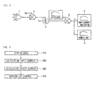
- Fig. 2 is a conceptual view of an LDC control method by an LDC control apparatus 100 according to an embodiment.
- the input current Ig of the LDC 20, the magnetization inductance Lm of the transformer 22 and the duty error d of the PWM controller are added by an adder 1.
- the magnetization inductance Lm of the transformer 22 and the duty error d of the PWM controller may be + components or - components with respect to the input current Ig component of the LDC 20, but this example describes when they are - components.
- the input voltage Vg of the LDC is multiplied by the output value of the adder 1 by using a multiplier 2.
- the output value of the multiplier 2 is divided by the output voltage Vo of the LDC 20 by using a divider 3.
- the output of the divider 3 is multiplied by the section efficiency eff of the LDC by using the multiplier 4 and the output current Io of the LDC is output.
- the output current Io of the LDC 20 may be used for an over current protection (OCP) function 5 or a power limit function 6.
- OCP over current protection
- the LDC control apparatus 100 includes a memory 110, an input current calculating unit 120, an output current calculating unit 130, and an LDC control unit 140.
- the LDC control apparatus 100 may be implemented in a digital signal processing (DSP) chip.
- the LDC control apparatus 100 may be implemented in the LDC 20.
- the LDC control apparatus 100 may be implemented in a programmable logic device (PLD).
- DSP digital signal processing
- PLD programmable logic device
- the memory 110 stores the inductance L of the transformer, the magnetization inductance Lm of the transformer, the duty D of the PWM controller, the duty error d of the PWM controller, the section efficiency eff of the LDC, the number n of primary windings of the transformer, and the number m of secondary windings of the transformer.
- the input current calculating unit 120 uses the magnetization inductance information Lm of the transformer and the effective duty D-d of the PWM controller to calculate the input current Ig of the LDC 20.
- the input current calculating unit 120 may use the inductance L of the transformer, the magnetization inductance Lm of the transformer, the duty D of the PWM controller, the duty error d of the PWM controller, the section efficiency eff of the LDC, the number n of primary windings of the transformer, and the number m of secondary windings of the transformer that are read from the memory 110; the input voltage Vg measured at the input of the LDC 20; and the output voltage Vo measured at the output of the LDC 20 to calculate the input current Ig of the LDC 20.
- the input current calculating unit 120 may compensate for the slope of the magnetization inductance information Lm of the transformer 120 and compensate for effective duty at which the input current is transferred from the PWM controller to the output to calculate the input current Ig of the LDC 140.
- the output current calculating unit 130 calculates the instantaneous value or average value of the output current based on the input current value calculated by the input current calculating unit 110.
- the LDC control unit 140 generates a control signal for OCP or power limit by the instantaneous value or average value of the output current calculated by the output current calculating unit 120 and outputs the generated signal to the PWM controller 24.
- the input current calculating unit 120 calculates the input current of the LDC 20.
- Input power Pin of the LDC 20 may be expressed as Equation 1 and the output current of the LDC 20 may be expressed as Equation 2.
- the input current calculating unit 120 applies several variables to Equation 3 above in order to compensate for an error in current information on the LDC 20.
- Equation 3 The slope Sn in Equation 3 may be represented as Equation 4 below when a duty change of the PWM controller 24 and the magnetization inductance of the transformer 22 are not considered.
- S n n ⁇ Vg - Vo ⁇ D L ⁇ 1 n ⁇ 1 m ⁇ eff
- the input current calculating unit 120 reflects current information due to the magnetization inductance Lm of the transformer 22 as an additional component based on Equation 2.
- Equation 4 may be represented as Equation 5.
- Equation 5 the additional component due to the magnetization inductance is not affected by the efficiency of the LDC 20.
- S n n ⁇ Vg - Vo ⁇ D L ⁇ 1 n ⁇ 1 m ⁇ eff + Vg ⁇ D L M ⁇ 1 m
- Equation 5 includes a component due to the duty error d of the PWN controller 24, Equation 6 below may be finally drawn.
- the duty error d represents a duty error occurring at the PWM controller 24.
- S n n ⁇ Vg - Vo ⁇ D - d L ⁇ 1 n ⁇ 1 m ⁇ eff + Vg ⁇ D - d L M ⁇ 1 m
- the input current calculating unit 120 obtains an input current value that approaches a more accurate value.
- the output current calculating unit 130 may calculate the instantaneous value and average value of an output current based on more accurate input current information calculated by the input current calculating unit 110. Thus, the output current calculating unit 130 may obtain an accurate value which has a smaller error.
- the LDC control unit 140 generates a control signal for OCP or power limit by the instantaneous current value or average current value calculated by the output current calculating unit 120 and outputs the generated signal to the PWM controller 24.
- the LDC control unit 140 may actually reflect the current and voltage states of the LDC 20, it is possible to increase the accuracy of when to operate a current limit function and a protection circuit by using output current information sensed at the output of the LDC 20.
- the effect of increasing the accuracy of output current information obtained by the present invention may be achieved by using magnetization inductance information obtained from the transformer 22 and effective duty information obtained from the PWM controller 24 in the LDC control process.
- the magnetization inductance value Lm obtained from the transformer 22 is information previously learning in a design step.
- the error d determining effective duty obtained from the PWM controller 24 is the sum of values considered when designing sensing network components on a current sensing circuit.
- the LDC control unit 140 may use peak current mode control by the instantaneous current value calculated by the output current calculating unit 130 and use an output current to perform LDC control.
- the LDC control unit 140 may regularly update the section efficiency eff of the LDC 20 on the memory 110.
- the LDC control unit 140 may use a charge current mode or an average current mode by the average current value calculated by the output current calculating unit 130 to perform LDC control.
- Fig. 3 is a flow chart of an LDC control method by an LDC control apparatus according to an embodiment.
- the LDC control method by the LDC control apparatus may include storing data in step S10, calculating an input current in step S20, calculating an output current in step S30, and performing LDC control in step S40.
- the storing of the data in step S10 may be performed by the memory 110.
- the inductance L of the transformer, the magnetization inductance Lm of the transformer, the duty D of the PWM controller, the duty error d of the PWM controller, the section efficiency eff of the LDC, the number n of primary windings of the transformer, and the number m of secondary windings of the transformer are stored in the memory 110.
- Step S20 where the input current is calculated uses magnetization inductance information on the transformer 22 and effective duty information on the PWM controller 24 to calculate the input current of the LDC.
- Step S20 where the input current is calculated may use the inductance L of the transformer, the magnetization inductance Lm of the transformer 22, the duty D of the PWM controller 24, the duty error d of the PWM controller, the section efficiency eff of the LDC 20, the number n of primary windings of the transformer, and the number m of secondary windings of the transformer that are read from the memory 110; the input voltage Vg measured at the input of the LDC 20; and the output voltage Vo measured at the output of the LDC 20 to calculate the input current of the LDC.
- Step S20 where the input current is calculated may compensate for the slope of the magnetization inductance information Lm of the transformer 22 and compensate for effective duty at which the input current is transferred from the PWM controller 24 to an output to calculate the input current of the LDC 20.
- Step S30 where the output current is calculated may be performed by the output current calculating unit 130.
- Step S30 where the output current is calculated calculates the instantaneous value and average value of the output current based on the input current calculated by step S20 where the input current is calculated.
- Step S40 where LDC is controlled may be performed by the LDC control unit 140.
- Step S40 where the LDC is controlled generates a control signal for OCP or power limit based on the instantaneous value and average value of the output current calculated by step S30 where the output current is calculated, and outputs the generated signal to the PWM controller.
- Step S40 where the LDC is controlled may regularly update the section efficiency eff of the LDC on the memory 110.
- the calculating of the input current, the calculating of the output current, and the generating and outputting of the control signal may be performed by a DSP chip.
- the calculating of the input current, the calculating of the output current, and the generating and outputting of the control signal may be performed by the LDC 20.
- the calculating of the input current, the calculating of the output current, and the generating and outputting of the control signal may be performed by a PLD.
- the present invention by using primary current information, namely, input current information on the transformer of the LDC, it is possible to decrease an error from a topology using a transformer, and by using magnetization inductance information on the transformer and effective duty information on a PWM controller for controlling the LDC, it is possible to provide an effect of increasing accuracy in controlling the LDC.
- primary current information namely, input current information on the transformer of the LDC
Landscapes
- Engineering & Computer Science (AREA)
- Power Engineering (AREA)
- Dc-Dc Converters (AREA)
Abstract
Description
- The present application claims priority under 35 U.S.C. 119 and 35 U.S.C. 365 to Korean Patent Application No.
10-2013-0158758 (filed on December 18, 2013 - The present disclosure relates to an apparatus and method for controlling a low voltage DC/DC converter (LDC) by using input current information on the LDC, and more particularly, to an apparatus and method for controlling the low voltage DC/DC converter (LDC) by using input current information on the LDC that may decrease an error from a topology using a transformer by using primary current information, namely, input current information on the transformer of an LDC in an electric vehicle, and use magnetization inductance information on the transformer and effective duty information on a PWM controller for controlling the LDC to enhance accuracy in controlling the LDC.
- Vehicles use fossil fuel such as gasoline or diesel and have developed according to a fundamental principle in which thermal energy is converted into a physical force through an engine. However, they started finding other power sources for some reasons such as environmental problems and the exhaustion of fuel due to the usage of fossil fuel, and electric energy based vehicles such as hybrid electric vehicles (HEV), plug-in-electric vehicles (PHEV), electric vehicles (EV) have been developed.
- In recent, research and development on electric components are being performed in order to produce products and preoccupy markets based on higher performance and efficiency beyond fundamental implementation.
- Electric components and peripheral elements on which research and development are being mainly performed include an on board charger (OBC), a low voltage DC/DC converter (LDC), and a battery pack. Each part is a main component related directly to the power of an EV and is an element that directly affects the performance of the EV.
- Among others, the LDC that receives an input voltage of 200 VDC to 450 VDC, converts the received voltage into a low voltage of 12 VDC, and supplies the low voltage to a battery and each part of the EV is one of the most important electric components in the EV.
- Due to the characteristic of the LDC requiring a high voltage transformation ratio, a DC/DC converter topology (phase shifted pull-bridge) that uses a transformer is commonly used.
- Typically, only a single variable, efficiency has been applied in representing the relation between an input voltage or current and an output voltage or current, and the assumption that the characteristics of physical elements configuring a circuit are all ideal has been used. When there is another variable, such an assumption may affect current control performance because errors in outputs increase. Also, such errors may limit the performance of the LDC in functions requiring current information having relatively high accuracy such as an output over current protection (OCP) function or a power limit (derating) function.
- Regarding limitations due to the occurrence of errors, the LDC that shows low voltage-high current output characteristics has a limitation in that it is difficult to wind the secondary windings of a transformer several times in consideration of entire efficiency. This leads to a decrease in the magnetization inductance Lm of a transformer increasing in proportion to the number of primary windings and the transformer is no longer ideal.
- Also, when a transfer ratio from an input voltage to an output voltage, effective duty Deff is not considered, actual current information has an error. When excluding the winding ratio n of a transformer, the duty representing the transfer ratio of the input/output voltage has various delay times in an actual configuration. Since the duty Deff considering a decrease in duty occurring on a transfer path appears, applying it to the process of drawing an output current is needed.
- Embodiments provide an apparatus and method for controlling a low voltage DC/DC converter (LDC) by using input current information on the LDC that may decrease an error from a topology using a transformer by using primary current information, namely, input current information on the transformer of an LDC in an electric vehicle, and use magnetization inductance information on the transformer and effective duty information on a PWM controller for controlling the LDC to enhance accuracy in controlling the LDC.
- The technical tasks of the present invention are not limited to the above-mentioned technical tasks and other technical tasks not mentioned will be able to be clearly understood by a person skilled in the art from the following descriptions.
- In one embodiment, a low voltage DC/DC converter (LDC) control apparatus for controlling an LDC including a transformer and a PWM controller includes an input current calculating unit calculating an input current of the LDC by using magnetization inductance information on the transformer and effective duty information on the PWM controller; an output current calculating unit calculating the instantaneous value and average value of an output current based on the input current calculated by the input current calculating unit; and an LDC control unit generating a control signal for over current protection (OCP) or power limit based on the instantaneous value and average value of the output current calculated by the output current calculating unit, wherein the LDC control unit outputs the generated control signal to the PWM controller.
- The low voltage DC/DC converter (LDC) control apparatus may further include a memory that stores the inductance L of the transformer, the magnetization inductance Lm of the transformer, the duty D of the PWM controller, the duty error d of the PWM controller, the section efficiency eff of the LDC, the number n of primary windings of the transformer, and the number m of secondary windings of the transformer.
- The input current calculating unit may use the inductance L of the transformer, the magnetization inductance Lm of the transformer, the duty D of the PWM controller, the duty error d of the PWM controller, the section efficiency eff of the LDC, the number n of primary windings of the transformer, and the number m of secondary windings of the transformer that are read from the memory; the input voltage of the LDC measured at the input of the
LDC 20; and the output voltage of the LDC measured at the output of the LDC to calculate the input current of the LDC. - The input current calculating unit may compensate for the slope of the magnetization inductance information Lm of the transformer and compensate for effective duty at which the input current is transferred from the PWM controller to the output to calculate the input current of the LDC.
- The input current calculating unit may calculate the input current of the LDC according to the following equations:


(where Ig: input current of LDC, Sn: sloep of input current waveform, Vg: input voltage of LDC, Vo: output voltage of LDC, D: duty of PWM controller, d: duty error of PWM controller, Lm: magnetization inductance of transformer, L: inductance of transformer, eff: section efficiency of LDC, n: number of primary windings of transformer, m: number of secondary windings of transformer, and Ts: period). - The LDC control unit may regularly update the section efficiency eff of the LDC on the memory.
- The input current calculating unit, the output current calculating unit, and the LDC control unit may use input current information on an LDC implemented in a digital signal processing (DSP) chip.
- The input current calculating unit, the output current calculating unit, and the LDC control unit may be implemented in the LDC.
- The input current calculating unit, the output current calculating unit, and the LDC control unit may be implemented in a programmable logic device (PLD).
- In another embodiment, a low voltage DC/DC converter (LDC) control method for controlling an LDC including a transformer and a PWM controller includes calculating, by an input current calculating unit, the input current of the LDC by using magnetization inductance information on the transformer and effective duty information on the PWM controller; calculating, by an output current calculating unit, the instantaneous value and average value of an output current based on the input current calculated; and generating, by an LDC control unit, a control signal for OCP or power limit based on the instantaneous value and average value of the output current calculated, and outputting the generated control signal to the PWM controller.
- The low voltage DC/DC converter (LDC) control method may further include storing, by a memory, the inductance L of the transformer, the magnetization inductance Lm of the transformer, the duty D of the PWM controller, the duty error d of the PWM controller, the section efficiency eff of the LDC, the number n of primary windings of the transformer, and the number m of secondary windings of the transformer.
- The calculating of the input current of the LDC may include using the inductance L of the transformer, the magnetization inductance Lm of the transformer, the duty D of the PWM controller, the duty error d of the PWM controller, the section efficiency eff of the LDC, the number n of primary windings of the transformer, and the number m of secondary windings of the transformer that are read from the memory; the input voltage of the LDC measured at the input of the LDC; and the output voltage of the LDC measured at the output of the LDC to calculate the input current of the LDC.
- The calculating of the input current of the LDC may include compensating for the slope of the magnetization inductance information Lm of the transformer and compensating for effective duty at which the input current is transferred from the PWM controller to the output to calculate the input current of the LDC.
- The calculating of the input current of the LDC may include calculating the input current of the LDC according to the following equations:


(where Ig: input current of LDC, Sn: sloep of input current waveform, Vg: input voltage of LDC, Vo: output voltage of LDC, D: duty of PWM controller, d: duty error of PWM controller, Lm: magnetization inductance of transformer, L: inductance of transformer, eff: section efficiency of LDC, n: number of primary windings of transformer, m: number of secondary windings of transformer, and Ts: period). - The generating of the control signal and the outputting the generated signal to the PWM controller may include regularly updating the section efficiency eff of the LDC on the memory.
- The calculating of the input current, the calculating of the output current, and the generating and outputting of the control signal may be performed in a DSP chip.
- The calculating of the input current, the calculating of the output current, and the generating and outputting of the control signal may be performed in the LDC.
- The calculating of the input current, the calculating of the output current, and the generating and outputting of the control signal may be performed in a PLD.
-
-
Fig. 1 is a block diagram of an LDC control apparatus according to an embodiment. -
Fig. 2 is a conceptual view of an LDC control method by an LDC control apparatus according to an embodiment. -
Fig. 3 is a flow chart of an LDC control method by an LDC control apparatus according to an embodiment. - Exemplary embodiments of the present invention are described below in detail with reference to the accompanying drawings. However, it may not be said that the spirit of the present invention is limited to presented embodiments, and it is possible to easily propose, by the addition, change or deletion of components, other retrogressive inventions or other embodiments included in the spirit of the present invention.
- The terms used herein are general terms currently, widely used if possible, but in particular cases, terms arbitrarily selected by the applicant are used and in these cases, since their meanings are described in detail in corresponding parts of the detailed description, it should be noted that the present invention needs to be understood with the meanings of the terms, not the names of the terms.
- That is, in the following description, the word "including" does not exclude the presence of components or steps other than those enumerated.
-
Fig. 1 is a block diagram of a low voltage DC/DC converter (LDC) control apparatus according to an embodiment. - Referring to
Fig. 1 , anLDC control apparatus 100 is electrically connected to apower supply unit 10, anLDC 20, a battery andload unit 30. - The
LDC control apparatus 100 performs LDC control by using the instantaneous values of the voltage and current information on theLDC 20 based on a switching frequency. - The LDC 20 includes a
switching unit 21, atransformer 22, anoutput filter 23, and aPWM controller 24. - The
switching unit 21 switches a current supplied from the power supply unit and transfers the switched current to thetransformer 22. Thetransformer 22 performs voltage transformation on power supplied through theswitching unit 21. For example, thetransformer 22 receives an input voltage of 200 VDC to 450 VDC, transforms the received voltage into a low voltage of 12 VDC, and outputs the low voltage to the battery andload unit 30. Theoutput filter 23 filters out noise from the output voltage obtained through the transformation and outputs noise-removed voltage. ThePWM controller 24 outputs a switching control signal to theswitching unit 21 according to the control signal of theLDC control apparatus 100 and performs correction on the input current and voltage. - The
LDC control apparatus 100 may reflect magnetization inductance information on thetransformer 22 and effective duty information on thePWM controller 24, calculate input current information on theLDC 20 and perform LDC control. -
Fig. 2 is a conceptual view of an LDC control method by anLDC control apparatus 100 according to an embodiment. - Referring to
Fig. 2 , the input current Ig of theLDC 20, the magnetization inductance Lm of thetransformer 22 and the duty error d of the PWM controller are added by an adder 1. In this case, the magnetization inductance Lm of thetransformer 22 and the duty error d of the PWM controller may be + components or - components with respect to the input current Ig component of theLDC 20, but this example describes when they are - components. The input voltage Vg of the LDC is multiplied by the output value of the adder 1 by using a multiplier 2. The output value of the multiplier 2 is divided by the output voltage Vo of theLDC 20 by using adivider 3. The output of thedivider 3 is multiplied by the section efficiency eff of the LDC by using themultiplier 4 and the output current Io of the LDC is output. The output current Io of theLDC 20 may be used for an over current protection (OCP)function 5 or apower limit function 6. - The
LDC control apparatus 100 includes amemory 110, an input current calculatingunit 120, an outputcurrent calculating unit 130, and anLDC control unit 140. - The
LDC control apparatus 100 may be implemented in a digital signal processing (DSP) chip. TheLDC control apparatus 100 may be implemented in theLDC 20. TheLDC control apparatus 100 may be implemented in a programmable logic device (PLD). - The
memory 110 stores the inductance L of the transformer, the magnetization inductance Lm of the transformer, the duty D of the PWM controller, the duty error d of the PWM controller, the section efficiency eff of the LDC, the number n of primary windings of the transformer, and the number m of secondary windings of the transformer. - The input current calculating
unit 120 uses the magnetization inductance information Lm of the transformer and the effective duty D-d of the PWM controller to calculate the input current Ig of theLDC 20. - The input current calculating
unit 120 may use the inductance L of the transformer, the magnetization inductance Lm of the transformer, the duty D of the PWM controller, the duty error d of the PWM controller, the section efficiency eff of the LDC, the number n of primary windings of the transformer, and the number m of secondary windings of the transformer that are read from thememory 110; the input voltage Vg measured at the input of theLDC 20; and the output voltage Vo measured at the output of theLDC 20 to calculate the input current Ig of theLDC 20. - The input current calculating
unit 120 may compensate for the slope of the magnetization inductance information Lm of thetransformer 120 and compensate for effective duty at which the input current is transferred from the PWM controller to the output to calculate the input current Ig of theLDC 140. - The output
current calculating unit 130 calculates the instantaneous value or average value of the output current based on the input current value calculated by the input current calculatingunit 110. - The
LDC control unit 140 generates a control signal for OCP or power limit by the instantaneous value or average value of the output current calculated by the outputcurrent calculating unit 120 and outputs the generated signal to thePWM controller 24. - The input current calculating
unit 120 calculates the input current of theLDC 20. - Input power Pin of the
LDC 20 may be expressed as Equation 1 and the output current of theLDC 20 may be expressed as Equation 2.

- Input current information on the LDC to which peak current mode control is applied based on the input current from the
power supply unit 10 may be expressed by the multiplication of the slope Sn and period Ts of a current waveform asEquation 3 below, based on an instantaneous value.
- The input current calculating
unit 120 applies several variables toEquation 3 above in order to compensate for an error in current information on theLDC 20. - The slope Sn in
Equation 3 may be represented asEquation 4 below when a duty change of thePWM controller 24 and the magnetization inductance of thetransformer 22 are not considered.
- The input current calculating
unit 120 reflects current information due to the magnetization inductance Lm of thetransformer 22 as an additional component based on Equation 2. - Thus,
Equation 4 may be represented asEquation 5. As could be seen inEquation 5, the additional component due to the magnetization inductance is not affected by the efficiency of theLDC 20.
- When
Equation 5 includes a component due to the duty error d of thePWN controller 24,Equation 6 below may be finally drawn. In this example, the duty error d represents a duty error occurring at thePWM controller 24.
- Since the slope Sn and the duty of the
PWM controller 24 are adjusted by current information due to the magnetization inductance Lm of thetransformer 22 and the duty error d component of thePWM controller 24, the input current calculatingunit 120 obtains an input current value that approaches a more accurate value. - The output
current calculating unit 130 may calculate the instantaneous value and average value of an output current based on more accurate input current information calculated by the input current calculatingunit 110. Thus, the outputcurrent calculating unit 130 may obtain an accurate value which has a smaller error. - The
LDC control unit 140 generates a control signal for OCP or power limit by the instantaneous current value or average current value calculated by the outputcurrent calculating unit 120 and outputs the generated signal to thePWM controller 24. Thus, since theLDC control unit 140 may actually reflect the current and voltage states of theLDC 20, it is possible to increase the accuracy of when to operate a current limit function and a protection circuit by using output current information sensed at the output of theLDC 20. - The effect of increasing the accuracy of output current information obtained by the present invention may be achieved by using magnetization inductance information obtained from the
transformer 22 and effective duty information obtained from thePWM controller 24 in the LDC control process. - The magnetization inductance value Lm obtained from the
transformer 22 is information previously learning in a design step. The error d determining effective duty obtained from thePWM controller 24 is the sum of values considered when designing sensing network components on a current sensing circuit. - The
LDC control unit 140 may use peak current mode control by the instantaneous current value calculated by the outputcurrent calculating unit 130 and use an output current to perform LDC control. - The
LDC control unit 140 may regularly update the section efficiency eff of theLDC 20 on thememory 110. - Also, the
LDC control unit 140 may use a charge current mode or an average current mode by the average current value calculated by the outputcurrent calculating unit 130 to perform LDC control. -
Fig. 3 is a flow chart of an LDC control method by an LDC control apparatus according to an embodiment. - Referring to
Fig. 3 , the LDC control method by the LDC control apparatus according to an embodiment may include storing data in step S10, calculating an input current in step S20, calculating an output current in step S30, and performing LDC control in step S40. - The storing of the data in step S10 may be performed by the
memory 110. In the storing of the data in step S10, the inductance L of the transformer, the magnetization inductance Lm of the transformer, the duty D of the PWM controller, the duty error d of the PWM controller, the section efficiency eff of the LDC, the number n of primary windings of the transformer, and the number m of secondary windings of the transformer are stored in thememory 110. - The calculating of the input current in step S20 may be performed by the input current calculating
unit 120. Step S20 where the input current is calculated uses magnetization inductance information on thetransformer 22 and effective duty information on thePWM controller 24 to calculate the input current of the LDC. - Step S20 where the input current is calculated may use the inductance L of the transformer, the magnetization inductance Lm of the
transformer 22, the duty D of thePWM controller 24, the duty error d of the PWM controller, the section efficiency eff of theLDC 20, the number n of primary windings of the transformer, and the number m of secondary windings of the transformer that are read from thememory 110; the input voltage Vg measured at the input of theLDC 20; and the output voltage Vo measured at the output of theLDC 20 to calculate the input current of the LDC. - Step S20 where the input current is calculated may compensate for the slope of the magnetization inductance information Lm of the
transformer 22 and compensate for effective duty at which the input current is transferred from thePWM controller 24 to an output to calculate the input current of theLDC 20. - Step S20 where the input current is calculated may calculate the input current of the
LDC 20 according to the following equations:

- Step S30 where the output current is calculated may be performed by the output
current calculating unit 130. Step S30 where the output current is calculated calculates the instantaneous value and average value of the output current based on the input current calculated by step S20 where the input current is calculated. - Step S40 where LDC is controlled may be performed by the
LDC control unit 140. Step S40 where the LDC is controlled generates a control signal for OCP or power limit based on the instantaneous value and average value of the output current calculated by step S30 where the output current is calculated, and outputs the generated signal to the PWM controller. - Step S40 where the LDC is controlled may regularly update the section efficiency eff of the LDC on the
memory 110. - The calculating of the input current, the calculating of the output current, and the generating and outputting of the control signal may be performed by a DSP chip.
- The calculating of the input current, the calculating of the output current, and the generating and outputting of the control signal may be performed by the
LDC 20. - The calculating of the input current, the calculating of the output current, and the generating and outputting of the control signal may be performed by a PLD.
- According to the present invention, by using primary current information, namely, input current information on the transformer of the LDC, it is possible to decrease an error from a topology using a transformer, and by using magnetization inductance information on the transformer and effective duty information on a PWM controller for controlling the LDC, it is possible to provide an effect of increasing accuracy in controlling the LDC.
- While particular embodiments have been described in the detailed description of the present invention, several variations may be made without departing from the scope of the present invention. Therefore, the scope of the present invention should not be limited to the above-described embodiments but be defined by the following claims and equivalents thereof.
Claims (18)
- A low voltage DC/DC converter (LDC) control apparatus for controlling an LDC including a transformer (22) and a PWM controller(24), the low voltage DC/DC converter (LDC) control apparatus comprising:an input current calculating unit(120) calculating an input current of the LDC by using magnetization inductance information on the transformer (22) and effective duty information on the PWM controller (24);an output current calculating unit(130) calculating the instantaneous value and average value of an output current based on the input current calculated by the input current calculating unit (120); andan LDC control unit (140) generating a control signal for over current protection (OCP) or power limit based on the instantaneous value and average value of the output current calculated by the output current calculating unit (130), wherein the LDC control unit(140) outputs the generated control signal to the PWM controller(24).
- The low voltage DC/DC converter (LDC) control apparatus according to claim 1, further comprising a memory (110) that stores the inductance L of the transformer (22), the magnetization inductance Lm of the transformer (22), the duty D of the PWM controller (24), the duty error d of the PWM controller(24), the section efficiency eff of the LDC, the number n of primary windings of the transformer (22), and the number m of secondary windings of the transformer (22).
- The low voltage DC/DC converter (LDC) control apparatus according to claim 1, wherein the input current calculating unit(120) uses the inductance L of the transformer (22), the magnetization inductance Lm of the transformer (22), the duty D of the PWM controller(24), the duty error d of the PWM controller(24), the section efficiency eff of the LDC, the number n of primary windings of the transformer (22), and the number m of secondary windings of the transformer (22) that are read from the memory (110); the input voltage of the LDC measured at the input of the LDC 20; and the output voltage of the LDC measured at the output of the LDC to calculate the input current of the LDC.
- The low voltage DC/DC converter (LDC) control apparatus according to claim 3, wherein the input current calculating unit(120) compensates for the slope of the magnetization inductance information Lm of the transformer (22) and compensates for effective duty at which the input current is transferred from the PWM controller (24) to the output to calculate the input current of the LDC.
- The low voltage DC/DC converter (LDC) control apparatus according to claim 4, wherein the input current calculating unit(120) calculates the input current of the LDC according to the following equations:


(where Ig: input current of LDC, Sn: sloep of input current waveform, Vg: input voltage of LDC, Vo: output voltage of LDC, D: duty of PWM controller(24), d: duty error of PWM controller (24), Lm: magnetization inductance of transformer (22), L: inductance of transformer (22), eff: section efficiency of LDC, n: number of primary windings of transformer (22), m: number of secondary windings of transformer (22), and Ts: period). - The low voltage DC/DC converter (LDC) control apparatus according to claim 2, wherein the LDC control unit(140) regularly updates the section efficiency eff of the LDC on the memory (110).
- The low voltage DC/DC converter (LDC) control apparatus according to claim 1, wherein the input current calculating unit(120), the output current calculating unit(130), and the LDC control unit(140) use input current information on an LDC implemented in a digital signal processing (DSP) chip.
- The low voltage DC/DC converter (LDC) control apparatus according to claim 1, wherein the input current calculating unit(120), the output current calculating unit(130), and the LDC control unit(140) are implemented in the LDC.
- The low voltage DC/DC converter (LDC) control apparatus according to claim 1, wherein the input current calculating unit(120), the output current calculating unit (130), and the LDC control unit(140) are implemented in a programmable logic device (PLD).
- A low voltage DC/DC converter (LDC) control method for controlling an LDC including a transformer (22) and a PWM controller(24), the low voltage DC/DC converter (LDC) control method comprising:calculating, by an input current calculating unit(120), the input current of the LDC by using magnetization inductance information on the transformer (22) and effective duty information on the PWM controller (24);calculating, by an output current calculating unit(130), the instantaneous value and average value of an output current based on the input current calculated; andgenerating, by an LDC control unit(140), a control signal for OCP or power limit based on the instantaneous value and average value of the output current calculated, and outputting the generated control signal to the PWM controller (24).
- The low voltage DC/DC converter (LDC) control method according to claim 10, further comprising storing, by a memory (110), the inductance L of the transformer (22), the magnetization inductance Lm of the transformer (22), the duty D of the PWM controller(24), the duty error d of the PWM controller(24), the section efficiency eff of the LDC, the number n of primary windings of the transformer (22), and the number m of secondary windings of the transformer (22).
- The low voltage DC/DC converter (LDC) control method according to claim 11, wherein the calculating of the input current of the LDC comprises using the inductance L of the transformer (22), the magnetization inductance Lm of the transformer (22), the duty D of the PWM controller (24), the duty error d of the PWM controller(24), the section efficiency eff of the LDC, the number n of primary windings of the transformer (22), and the number m of secondary windings of the transformer (22) that are read from the memory (110); the input voltage of the LDC measured at the input of the LDC; and the output voltage of the LDC measured at the output of the LDC to calculate the input current of the LDC.
- The low voltage DC/DC converter (LDC) control method according to claim 12, wherein the calculating of the input current of the LDC comprises compensating for the slope of the magnetization inductance information Lm of the transformer (22) and compensating for effective duty at which the input current is transferred from the PWM controller(24) to the output to calculate the input current of the LDC.
- The low voltage DC/DC converter (LDC) control method according to claim 13, wherein the calculating of the input current of the LDC comprises calculating the input current of the LDC according to the following equations:


- The low voltage DC/DC converter (LDC) control method according to claim 11, wherein the generating of the control signal and the outputting the generated signal to the PWM controller(24) comprise regularly updating the section efficiency eff of the LDC on the memory (110).
- The low voltage DC/DC converter (LDC) control method according to claim 10, wherein the calculating of the input current, the calculating of the output current, and the generating and outputting of the control signal are performed in a DSP chip.
- The low voltage DC/DC converter (LDC) control method according to claim 10, wherein the calculating of the input current, the calculating of the output current, and the generating and outputting of the control signal are performed in the LDC.
- The low voltage DC/DC converter (LDC) control method according to claim 10, wherein the calculating of the input current, the calculating of the output current, and the generating and outputting of the control signal are performed in a PLD.
Applications Claiming Priority (1)
| Application Number | Priority Date | Filing Date | Title |
|---|---|---|---|
| KR1020130158758A KR20150071575A (en) | 2013-12-18 | 2013-12-18 | Apparatus for controlling low voltage dc/dc converter using input current information of low voltage dc/dc converter |
Publications (2)
| Publication Number | Publication Date |
|---|---|
| EP2887522A2 true EP2887522A2 (en) | 2015-06-24 |
| EP2887522A3 EP2887522A3 (en) | 2015-11-04 |
Family
ID=51211695
Family Applications (1)
| Application Number | Title | Priority Date | Filing Date |
|---|---|---|---|
| EP14178135.1A Withdrawn EP2887522A3 (en) | 2013-12-18 | 2014-07-23 | Apparatus and method for controlling low voltage dc/dc converter by using input current information on low voltage dc/dc converter |
Country Status (5)
| Country | Link |
|---|---|
| US (1) | US9473012B2 (en) |
| EP (1) | EP2887522A3 (en) |
| JP (1) | JP2015119618A (en) |
| KR (1) | KR20150071575A (en) |
| CN (1) | CN104734508A (en) |
Families Citing this family (8)
| Publication number | Priority date | Publication date | Assignee | Title |
|---|---|---|---|---|
| KR101755897B1 (en) | 2015-11-25 | 2017-07-07 | 현대자동차주식회사 | Low voltage dc-dc converter of eco friendly vehicle |
| KR101822280B1 (en) * | 2016-05-04 | 2018-01-26 | 현대자동차주식회사 | Method for correcting output voltage sensing error of low voltage dc-dc converter |
| KR101993598B1 (en) * | 2016-05-31 | 2019-06-27 | 주진관 | Power supply apparatus of mobile car having charge-discharge device of secondary batteries |
| KR101947242B1 (en) | 2016-11-29 | 2019-02-12 | 현대자동차주식회사 | System and Method for controlling voltage of LDC of vehicle |
| KR102506849B1 (en) * | 2016-12-13 | 2023-03-08 | 현대자동차주식회사 | Apparatus and method for controlling ldc of hybrid vehicle |
| CN110867962B (en) * | 2019-11-20 | 2021-04-30 | 贵州电网有限责任公司电力科学研究院 | Method and device for verifying power distribution network wrong topological relation based on feeder line contact group |
| KR102890051B1 (en) * | 2020-12-24 | 2025-11-24 | 현대모비스 주식회사 | Peak current control apparatus and method for LDC, by using combination of digital and analog circuits |
| CN118249475B (en) * | 2024-05-27 | 2025-05-02 | 荣耀终端股份有限公司 | Charging method, charging module, electronic equipment and storage medium |
Family Cites Families (13)
| Publication number | Priority date | Publication date | Assignee | Title |
|---|---|---|---|---|
| JP2000269759A (en) * | 1999-03-18 | 2000-09-29 | Matsushita Electric Ind Co Ltd | Automatic gain control circuit, receiving apparatus including the circuit, automatic gain control method in receiving apparatus, and recording medium |
| DE60210217T2 (en) * | 2001-01-31 | 2006-11-16 | Matsushita Electric Industrial Co., Ltd., Kadoma | SMPS device |
| CN1830199A (en) * | 2003-05-29 | 2006-09-06 | Tdk半导体公司 | Method and apparatus for full-duplex signal across transformer |
| JP4677292B2 (en) | 2005-06-20 | 2011-04-27 | オリジン電気株式会社 | Power supply |
| GB2436155A (en) | 2006-03-14 | 2007-09-19 | Cambridge Semiconductor Ltd | Switch mode power supply current sensing |
| GB2439998A (en) * | 2006-07-07 | 2008-01-16 | Cambridge Semiconductor Ltd | Estimating the output current of a switch mode power supply |
| KR101103616B1 (en) | 2008-01-07 | 2012-01-09 | 에스케이이노베이션 주식회사 | Pre-Charge Protection Circuit Device Using Interlock Switch |
| US8116105B2 (en) * | 2008-02-07 | 2012-02-14 | American Power Conversion Corporation | Systems and methods for uninterruptible power supply control |
| JP5092023B2 (en) | 2009-02-06 | 2012-12-05 | 新電元工業株式会社 | Current detection circuit and transformer current measurement system |
| JP2011130562A (en) | 2009-12-16 | 2011-06-30 | Origin Electric Co Ltd | Low-side current detecting circuit |
| EP2375854B1 (en) * | 2010-04-06 | 2015-12-02 | Plastic Omnium Advanced Innovation and Research | Heater for a vehicular fluid tank, motor vehicle comprising same, and method for heating a vehicular fluid tank |
| JP2013046438A (en) | 2011-08-22 | 2013-03-04 | Omron Automotive Electronics Co Ltd | Dc-dc converter |
| JP2014126699A (en) * | 2012-12-26 | 2014-07-07 | Sony Corp | Self-luminous display device, and control method and computer program for self-luminous display device |
-
2013
- 2013-12-18 KR KR1020130158758A patent/KR20150071575A/en not_active Ceased
-
2014
- 2014-07-22 US US14/338,142 patent/US9473012B2/en not_active Expired - Fee Related
- 2014-07-23 EP EP14178135.1A patent/EP2887522A3/en not_active Withdrawn
- 2014-08-22 JP JP2014169223A patent/JP2015119618A/en active Pending
- 2014-10-28 CN CN201410588800.XA patent/CN104734508A/en active Pending
Non-Patent Citations (1)
| Title |
|---|
| None |
Also Published As
| Publication number | Publication date |
|---|---|
| JP2015119618A (en) | 2015-06-25 |
| US9473012B2 (en) | 2016-10-18 |
| EP2887522A3 (en) | 2015-11-04 |
| CN104734508A (en) | 2015-06-24 |
| US20150171725A1 (en) | 2015-06-18 |
| KR20150071575A (en) | 2015-06-26 |
Similar Documents
| Publication | Publication Date | Title |
|---|---|---|
| US9473012B2 (en) | Apparatus and method for controlling low voltage DC/DC converter by using input current information on low voltage DC/DC converter | |
| Chen et al. | New digital-controlled technique for battery charger with constant current and voltage control without current feedback | |
| Naayagi et al. | Bidirectional control of a dual active bridge DC–DC converter for aerospace applications | |
| US10160338B1 (en) | Control system and method for on-board battery charger of vehicle | |
| HUE029351T2 (en) | Method and device for testing the drive train of vehicles driven at least partially by electricity | |
| KR20200050950A (en) | Electrical architecture for electrochemical impedance spectroscopy | |
| EP3499676A1 (en) | Power converter | |
| US20160006358A1 (en) | Control circuit | |
| CN115706507A (en) | Apparatus and method for controlling LLC resonant converter | |
| US20180138817A1 (en) | Knee point detection for power converter control | |
| Jianhua et al. | Modeling and analysis of a buck/boost bidirectional converter with developed PWM switch model | |
| Zhang et al. | A unified numerical modeling method for dual active bridge type converter | |
| Pepa | Adaptive control of a step-up full-bridge dc-dc converter for variable low input voltage applications | |
| US12580472B2 (en) | Apparatus and method for controlling bidirectional resonant DC-DC converters | |
| US10239408B2 (en) | Apparatus and method for controlling low voltage direct current converter for eco-friendly vehicle | |
| Du et al. | Droop controller design methods for isolated DC-DC converter in DC grid battery energy storage applications | |
| US8279638B2 (en) | Output regulation circuit of a power converter without current sensing loss and method thereof | |
| Mohareb | Efficiency Enhanced DC-DC Converter Using Dynamic Inductor Control | |
| US20150028825A1 (en) | Control Circuit, Control Method, DC-DC Converter and Electronic Device | |
| Daneshpajooh et al. | Modeling of the phase shift plus duty cycle controlled half bridge DC to DC converter | |
| EP4092897A1 (en) | Bidirectional dc/dc converter and control method therefor and apparatus thereof, and storage medium | |
| Sawant et al. | Closed-Loop Adaptive Frequency and Phase-Shift Control of Bidirectional Class-E² Converter for Energy Storage Applications | |
| Hmam et al. | A cycle-based formulation for the simulation of multi time-scale systems—Application to the modeling of the storage system of a fully electric ferry | |
| JP6384422B2 (en) | Control device for power converter | |
| JP6464034B2 (en) | Power converter |
Legal Events
| Date | Code | Title | Description |
|---|---|---|---|
| PUAI | Public reference made under article 153(3) epc to a published international application that has entered the european phase |
Free format text: ORIGINAL CODE: 0009012 |
|
| 17P | Request for examination filed |
Effective date: 20140723 |
|
| AK | Designated contracting states |
Kind code of ref document: A2 Designated state(s): AL AT BE BG CH CY CZ DE DK EE ES FI FR GB GR HR HU IE IS IT LI LT LU LV MC MK MT NL NO PL PT RO RS SE SI SK SM TR |
|
| AX | Request for extension of the european patent |
Extension state: BA ME |
|
| PUAL | Search report despatched |
Free format text: ORIGINAL CODE: 0009013 |
|
| AK | Designated contracting states |
Kind code of ref document: A3 Designated state(s): AL AT BE BG CH CY CZ DE DK EE ES FI FR GB GR HR HU IE IS IT LI LT LU LV MC MK MT NL NO PL PT RO RS SE SI SK SM TR |
|
| AX | Request for extension of the european patent |
Extension state: BA ME |
|
| RIC1 | Information provided on ipc code assigned before grant |
Ipc: H02M 3/335 20060101AFI20150925BHEP |
|
| STAA | Information on the status of an ep patent application or granted ep patent |
Free format text: STATUS: THE APPLICATION IS DEEMED TO BE WITHDRAWN |
|
| 18D | Application deemed to be withdrawn |
Effective date: 20160505 |