EP2887261B1 - Information processing device, information processing method, and program - Google Patents
Information processing device, information processing method, and program Download PDFInfo
- Publication number
- EP2887261B1 EP2887261B1 EP14189271.1A EP14189271A EP2887261B1 EP 2887261 B1 EP2887261 B1 EP 2887261B1 EP 14189271 A EP14189271 A EP 14189271A EP 2887261 B1 EP2887261 B1 EP 2887261B1
- Authority
- EP
- European Patent Office
- Prior art keywords
- image
- feature amount
- specific object
- filter
- board
- Prior art date
- Legal status (The legal status is an assumption and is not a legal conclusion. Google has not performed a legal analysis and makes no representation as to the accuracy of the status listed.)
- Active
Links
Images


Classifications
-
- G—PHYSICS
- G06—COMPUTING; CALCULATING OR COUNTING
- G06V—IMAGE OR VIDEO RECOGNITION OR UNDERSTANDING
- G06V10/00—Arrangements for image or video recognition or understanding
- G06V10/70—Arrangements for image or video recognition or understanding using pattern recognition or machine learning
- G06V10/77—Processing image or video features in feature spaces; using data integration or data reduction, e.g. principal component analysis [PCA] or independent component analysis [ICA] or self-organising maps [SOM]; Blind source separation
- G06V10/774—Generating sets of training patterns; Bootstrap methods, e.g. bagging or boosting
- G06V10/7747—Organisation of the process, e.g. bagging or boosting
-
- G—PHYSICS
- G06—COMPUTING; CALCULATING OR COUNTING
- G06F—ELECTRIC DIGITAL DATA PROCESSING
- G06F18/00—Pattern recognition
- G06F18/20—Analysing
- G06F18/21—Design or setup of recognition systems or techniques; Extraction of features in feature space; Blind source separation
- G06F18/214—Generating training patterns; Bootstrap methods, e.g. bagging or boosting
- G06F18/2148—Generating training patterns; Bootstrap methods, e.g. bagging or boosting characterised by the process organisation or structure, e.g. boosting cascade
-
- G—PHYSICS
- G06—COMPUTING; CALCULATING OR COUNTING
- G06F—ELECTRIC DIGITAL DATA PROCESSING
- G06F3/00—Input arrangements for transferring data to be processed into a form capable of being handled by the computer; Output arrangements for transferring data from processing unit to output unit, e.g. interface arrangements
- G06F3/01—Input arrangements or combined input and output arrangements for interaction between user and computer
- G06F3/03—Arrangements for converting the position or the displacement of a member into a coded form
- G06F3/041—Digitisers, e.g. for touch screens or touch pads, characterised by the transducing means
- G06F3/042—Digitisers, e.g. for touch screens or touch pads, characterised by the transducing means by opto-electronic means
- G06F3/0428—Digitisers, e.g. for touch screens or touch pads, characterised by the transducing means by opto-electronic means by sensing at the edges of the touch surface the interruption of optical paths, e.g. an illumination plane, parallel to the touch surface which may be virtual
-
- G—PHYSICS
- G06—COMPUTING; CALCULATING OR COUNTING
- G06V—IMAGE OR VIDEO RECOGNITION OR UNDERSTANDING
- G06V10/00—Arrangements for image or video recognition or understanding
- G06V10/40—Extraction of image or video features
- G06V10/44—Local feature extraction by analysis of parts of the pattern, e.g. by detecting edges, contours, loops, corners, strokes or intersections; Connectivity analysis, e.g. of connected components
- G06V10/443—Local feature extraction by analysis of parts of the pattern, e.g. by detecting edges, contours, loops, corners, strokes or intersections; Connectivity analysis, e.g. of connected components by matching or filtering
- G06V10/446—Local feature extraction by analysis of parts of the pattern, e.g. by detecting edges, contours, loops, corners, strokes or intersections; Connectivity analysis, e.g. of connected components by matching or filtering using Haar-like filters, e.g. using integral image techniques
-
- G—PHYSICS
- G06—COMPUTING; CALCULATING OR COUNTING
- G06V—IMAGE OR VIDEO RECOGNITION OR UNDERSTANDING
- G06V10/00—Arrangements for image or video recognition or understanding
- G06V10/40—Extraction of image or video features
- G06V10/44—Local feature extraction by analysis of parts of the pattern, e.g. by detecting edges, contours, loops, corners, strokes or intersections; Connectivity analysis, e.g. of connected components
- G06V10/443—Local feature extraction by analysis of parts of the pattern, e.g. by detecting edges, contours, loops, corners, strokes or intersections; Connectivity analysis, e.g. of connected components by matching or filtering
- G06V10/449—Biologically inspired filters, e.g. difference of Gaussians [DoG] or Gabor filters
-
- G—PHYSICS
- G06—COMPUTING; CALCULATING OR COUNTING
- G06V—IMAGE OR VIDEO RECOGNITION OR UNDERSTANDING
- G06V40/00—Recognition of biometric, human-related or animal-related patterns in image or video data
- G06V40/10—Human or animal bodies, e.g. vehicle occupants or pedestrians; Body parts, e.g. hands
- G06V40/107—Static hand or arm
- G06V40/11—Hand-related biometrics; Hand pose recognition
-
- G—PHYSICS
- G06—COMPUTING; CALCULATING OR COUNTING
- G06V—IMAGE OR VIDEO RECOGNITION OR UNDERSTANDING
- G06V40/00—Recognition of biometric, human-related or animal-related patterns in image or video data
- G06V40/10—Human or animal bodies, e.g. vehicle occupants or pedestrians; Body parts, e.g. hands
- G06V40/16—Human faces, e.g. facial parts, sketches or expressions
- G06V40/161—Detection; Localisation; Normalisation
-
- G—PHYSICS
- G06—COMPUTING; CALCULATING OR COUNTING
- G06F—ELECTRIC DIGITAL DATA PROCESSING
- G06F2203/00—Indexing scheme relating to G06F3/00 - G06F3/048
- G06F2203/041—Indexing scheme relating to G06F3/041 - G06F3/045
- G06F2203/04108—Touchless 2D- digitiser, i.e. digitiser detecting the X/Y position of the input means, finger or stylus, also when it does not touch, but is proximate to the digitiser's interaction surface without distance measurement in the Z direction
-
- G—PHYSICS
- G06—COMPUTING; CALCULATING OR COUNTING
- G06F—ELECTRIC DIGITAL DATA PROCESSING
- G06F2218/00—Aspects of pattern recognition specially adapted for signal processing
- G06F2218/02—Preprocessing
-
- G—PHYSICS
- G06—COMPUTING; CALCULATING OR COUNTING
- G06F—ELECTRIC DIGITAL DATA PROCESSING
- G06F2218/00—Aspects of pattern recognition specially adapted for signal processing
- G06F2218/08—Feature extraction
Definitions
- the present disclosure relates to an information processing device, an information processing method, and a program, for example, to an information processing device, an information processing method, and a program analyzing presence or absence or the position of a specific object based on an image photographed by a camera.
- a distance analysis process may be used which uses a stereo camera as a system analyzing the position of a subject photographed in an image.
- This process may be a process of analyzing corresponding points of two images photographed from two different positions and calculating a distance (depth) from a camera to a subject based on information regarding the corresponding points.
- a process using a feature amount may be used as a process of detecting a specific object, e.g., a human face or hand, from an image.
- This process may be a process of acquiring image data indicating a feature amount of a detection target in advance and detecting an image region similar to the feature amount in a photographed image. For example, when a human face is detected, image data indicating a feature amount of a human face is acquired in advance and an image region having the feature amount similar to the feature amount in a photographed image is determined as a face region.
- the feature amount for example, a feature amount which can be obtained by extracting an edge in an image is used.
- a target object may be detected by accumulating a plurality of pieces of feature amount data by a learning process performed in advance and comparing the accumulated learning data to an image region included in a photographed image (see U.S. Patent Application Publication No. 2004/0013304 , U.S. Patent Application Publication No. 2002/0102034 , and U.S. Patent No. 7,099,510 ).
- An image recognition device includes an image acquiring unit configured to acquire an image, and an object recognition unit configured to calculate gradient directions and gradient values of intensity of the image acquired by the image acquiring unit, to scan the gradient values of each acquired gradient direction with a window, to calculate a rectangular feature value, and to recognize a target object using a classifier based on the rectangular feature value.
- US2011157040 A1 discloses a touchpanel device which includes an approach determining unit configured to determine based on acquired image information whether an object has approached to or touched a touchscreen.
- a region similar to a specific feature amount can be detected in one image and an image region of a specific object can be specified, but a spatial position of the object is not determined.
- an information processing device including a feature amount extraction unit configured to extract each feature amount from a connected image generated by connecting images photographed from different viewpoints; and a specific object recognition unit configured to perform a process of determining a position of a specific object based on the feature amount extracted by the feature amount extraction unit.
- the feature amount extraction unit performs a feature amount extraction process to which a separated filter in which filter-formed regions are set to be separated is applied.
- the feature amount extraction unit may perform the feature amount extraction process by setting the separated filter regions forming the separated filter in two images of the connected image.
- the feature amount extraction unit may extract the feature amount by selectively applying filters determined to have high discrimination in first and second states of the specific object in a learning process performed in advance.
- the information processing device may further include a learning processing unit configured to perform a process of determining the filter with high discrimination by inputting a plurality of connected images indicating the first and second states of the specific object and extracting the feature amounts to which separated filters with different formats are applied.
- a learning processing unit configured to perform a process of determining the filter with high discrimination by inputting a plurality of connected images indicating the first and second states of the specific object and extracting the feature amounts to which separated filters with different formats are applied.
- the specific object recognition unit may calculate a score by adding the feature amounts corresponding to the different separated filters and extracted by the feature amount extraction unit and perform the process of determining the position of the specific object based on the added score.
- the specific object recognition unit may calculate scores corresponding to pixels and obtained by adding the feature amounts corresponding to the pixels corresponding to the different separated filters and extracted by the feature amount extraction unit and perform the process of determining the position of the specific object based on a total score obtained by further adding the calculated scores corresponding to the pixels.
- the feature amount extraction unit may calculate the feature amount as an index value used to distinguish a first state in which a finger, which is the specific object, comes into contact with a board from a second state in which the finger does not come into contact with the board.
- the specific object recognition unit may perform a process of determining whether the finger which is the specific object comes into contact with the board.
- the feature amount extraction unit may further extract the feature amount as the index value used to determine whether the specific object is present in an image. Based on the feature amount extracted by the feature amount extraction unit, the specific object recognition unit may perform a specific object detection process of determining whether the specific object is present or absent.
- the separated filter may be a filter in which filter regions with different luminance are set to be separated.
- the feature amount extraction unit may extract the feature amount by setting the separated filter on an epipolar line corresponding to a feature point of one image of the connected image and the feature point on the other image of the connected image.
- an information processing method performed in an information processing device.
- the method includes extracting, by a feature amount extraction unit, a feature amount from a connected image generated by connecting images photographed from different viewpoints; and performing, by a specific object recognition unit, a process of determining a position of a specific object based on the feature amount extracted by the feature amount extraction unit.
- the feature amount extraction unit performs a feature amount extraction process to which a separated filter in which filter-formed regions are set to be separated is applied.
- a program causing an information processing device to perform information processing.
- the program causes a feature amount extraction unit to extract a feature amount from a connected image generated by connecting images photographed from different viewpoints; a specific object recognition unit to perform a process of determining a position of a specific object based on the feature amount extracted by the feature amount extraction unit; and the feature amount extraction unit to perform a feature amount extraction process to which a separated filter in which filter-formed regions are set to be separated is applied.
- the program according to an embodiment of the present disclosure is a program which can be supplied to an information processing device or a computer system capable of executing various program codes by a communication medium or a storage medium supplying the program in a computer-readable format.
- a process is realized according to the program on the information processing device or the computer system.
- a system in the present specification refers to a logical collection of a plurality of devices and is not limited to a configuration in which constituent devices are present in the same casing.
- a device and a method are realized in which the specific object position determination process is performed based on the feature amount extracted from the connected image of the images photographed from the different viewpoints.
- each feature amount is extracted from a connected image generated by connecting images photographed from different viewpoints and a process of determining a position of a specific object is performed based on the feature amount extracted by the feature amount extraction unit.
- a feature amount extraction unit performs a feature amount extraction process to which a separated filter in which filter-formed regions are set to be separated is applied and performs the feature amount extraction process by setting the separated filter regions forming the separated filter in two images of the connected image.
- a specific object recognition unit performs a specific object position determination process based on a score by adding the feature amounts corresponding to the different separated filters and extracted by the feature amount extraction unit.
- the device and the method are realized in which the specific object position determination process is performed based on the feature amount extracted from the connected image of the images photographed from the different viewpoints.
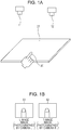
- Fig. 1A is a diagram illustrating an example of an image photography environment.
- Fig. 1A illustrates a state in which the human finger 30 is present on the board 21 and the finger 30 comes into contact with (touches) the board 21.
- the finger 30 is moved frequently and does not come into contact with the board 21 in some cases or is distant from the board 21 and is not present on the board 21 in some cases.
- the information processing device determines the foregoing three states based on images photographed by two cameras illustrated in Figs. 1A and 1B , i.e., a camera L11 and a camera R12.
- the camera L11 is fixed at a position on the upper left side when viewed from the center of the board 21 and photographs a plane of the board 21 from the upper left side.
- the camera R12 is fixed at a position on the upper right side when viewed from the center of the board 21 and photographs the plane of the board 21 from the upper right side.
- FIG. 1B An example of the image photographed by each camera is illustrated in Fig. 1B .
- An L image 51 is an image photographed by the camera L11.
- An R image 52 is an image photographed by the camera R12.
- the examples of the images are the photographed images in the state in which the finger 30 comes into contact with the board 21.
- the images photographed by the camera L11 and the camera L12 may be still images or moving images.
- the state of the finger 30 is determined among the foregoing (state 1) to (state 3) using the two photographed still images.
- the state of the finger 30 is determined among the foregoing (state 1) to (state 3), for example, in photography frame units or predefined predetermined frame intervals.
- the information processing device inputs, for example, the images photographed by the camera L11 and the camera R12 set at two different positions illustrated in Figs. 1A and 1B and performs a process of determining a state of the finger 30 among the above-described states, i.e., the following three states based on these images:
- the information processing device performs a finger detection process of determining whether the finger is included in the photographed image. This process is performed using only one image between the L image 51 and the R image 52 illustrated in Fig. 1B .
- step S102 the information processing device determines whether the finger is detected from the photographed image.
- step S103 An analysis result indicating that the finger is not detected is output, and the process proceeds to step S108.
- An output destination of the analysis result is a data processing unit that performs a process according to the analysis result, and may be a data processing unit in the information processing device or may be an external device connected to the information processing device.
- step S102 When it is determined in step S102 that the finger is detected in the photographed image, the process proceeds to step S104.
- step S104 a contact determination process is performed as a finger position detection process to determine whether the finger comes into contact with (touches) the board.
- the L image 51 and the R image 52 illustrated in Fig. 1B i.e., the plurality of images photographed from different viewpoints, are used.
- the learning data indicating feature amounts accumulated in advance is also used. A specific example of this process will be described later.
- step S105 the information processing device determines whether the finger detected from the photographed image comes into contact with the board. When it is determined that the finger does not come into contact with the board, the process proceeds to step S106. An analysis result indicating that the finger does not come into contact with the board is output and the process proceeds to step S108.
- step S107 An analysis result indicating that the finger comes into contact with the board is output and the process proceeds to step S108.
- An output destination of the analysis result is a data processing unit that performs a process according to the analysis result, and may be a data processing unit in the information processing device or may be an external device connected to the information processing device.
- step S108 the information processing device determines whether the analysis process ends.
- an image to be analyzed is not input, it is determined that the process ends.
- the process according to the flow illustrated in Fig. 2 is performed repeatedly at predetermined frame intervals. In this case, the determination of step S108 is NO, and thus the process returns to step S101 and the analysis process of step S101 and the subsequent steps is repeatedly performed on a new input image.
- the information processing device performs the object detection process based on one photographed image, applies an image photographed continuously from a different viewpoint, and performs the object position determination process.
- the object detection process is performed as a finger detection process and the object position determination process is performed as a process of determining two states regarding whether the finger comes into contact with the board.
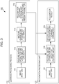
- An information processing device 100 includes a learning processing unit 110 and a recognition processing unit 120.
- the learning processing unit 110 includes an image input unit 111, a feature amount extraction unit 112, a machine learning unit 113, and a recognition dictionary storage unit 114.
- the learning processing unit 110 inputs a plurality of images as learning images and the recognition processing unit 120 generates a recognition dictionary used in a process of discriminating presence or absence of a specific object or the position of the specific object from the image based on the learning images.
- the generated recognition dictionary is stored in the recognition dictionary storage unit 114.
- the recognition processing unit 120 includes an image input unit 121, a feature amount extraction unit 122, and a specific object recognition unit 123.
- the recognition processing unit 120 inputs an analysis target image and performs a process of detecting a specific object and determining the position of the specific object.
- the recognition processing unit 120 performs the process of detecting the specific object and determining the position of the specific object using the recognition dictionary generated based on the learning data by the learning processing unit 110 and stored in the recognition dictionary storage unit 114.
- the information processing device 100 illustrated in Fig. 3 performs the following two processes, as described above with reference to the flow illustrated in Fig. 2 .
- the learning processing unit 110 of the information processing device 100 generates recognition dictionaries as learning data applied to the foregoing (process 1) and (process 2).
- the recognition processing unit 120 performs each of the following process by individually applying the recognition dictionaries corresponding to the foregoing (process 1) and (process 2) generated by the learning processing unit, i.e.:
- the learning processing unit 110 inputs the plurality of photographed images as learning images from the image input unit 111.
- the learning images are, for example, a plurality of images photographed in the photography environment described with reference to Fig. 1A .
- the learning images include a plurality of images in the following states:
- attribute information (a label, a tag, or the like) indicating in which state each image is among the foregoing states is set.
- the feature amount extraction unit 112 extracts a feature amount included in the learning image input from the image input unit 111.
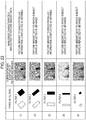
- various filters are used. Examples of rectangular filters applied to the feature amount extraction are illustrated in Figs. 4A to 5B .
- First differential filters illustrated in Fig. 4A are filters appropriate for a process of extracting a pixel region that has a feature in which a change direction is from white to black or from black to white in an image from an input image.
- Vertical or horizontal direction filters can efficiently extract a pixel region when the change direction from white to black or from black to white is a vertical or horizontal direction.
- Oblique direction filters can efficiently extract a pixel region when the change direction from white to black or from black to white is an oblique direction.
- Second differential filters illustrated in Fig. 4B are filters appropriate for a process of extracting a pixel region having a feature in which a change direction is white/black/white or black/white/black in an image from an input image.
- Vertical or horizontal direction filters can efficiently extract a pixel region when the change direction is a vertical or horizontal direction.
- the oblique direction filters can efficiently extract a pixel region when the change direction is an oblique direction.
- Third differential filters illustrated in Fig. 5A are filters appropriate for a process of extracting a pixel region having a feature in which a change direction is white/black/white/black or black/white/black/white in an image from an input image.
- Vertical or horizontal direction filters can efficiently extract a pixel region when the change direction is a vertical or horizontal direction.
- the oblique direction filters can efficiently extract a pixel region when the change direction is an oblique direction.
- the rectangular filters illustrated in Figs. 4A, 4B , and 5A are known filters that are used to extract a feature amount in the related art.
- Fig. 5B Separated filters illustrated in Fig. 5B are filters that are not known filters, but are devised as filters used for the object position determination process performed by the information processing device according to an embodiment of the present disclosure.
- the separated filters are filters that are used to determine the position of the finger 30 illustrated in Figs. 1A and 1B , specifically, to determine whether the finger 30 comes into contact with the board 21.
- the separated filters illustrated in Fig. 5B have a feature in which white and black patterns are set to be separate. This feature is different from that of the first to third differential filters illustrated in Figs. 4A, 4B , and 5A .
- Fig. 6 is a diagram for describing an example of a process of extracting a pixel region having the same change region from images by applying a filter 130 which is shown in the upper left end of the first differential filters illustrated in Fig. 4A and in which the change direction is the horizontal direction from black to white.
- the filter calculation is performed according to an expression below, as illustrated.
- G d ⁇ ⁇ I x i y i s i
- G d, ⁇ is a d-th differential function of a Gauss function G corresponding to each filter described with reference to Figs. 4A to 5B .
- d corresponds to an order described with reference to Figs. 4A to 5B
- ⁇ corresponds to the angle of the filter, i.e., a set angle of the filter at a vertical or horizontal angle (0° or 90°), an oblique angle (45° or 135°), or the like described with reference to Figs. 4A to 5B .
- (x i , y i ) in I (x i , y i , s i ) indicates the position of a pixel
- si means the scale of an image
- i is a scale discriminator of an image to be applied.
- I (x i , y i , s i ) presents a pixel value at the pixel position (x i , y i ) of an image with the scale si, e.g., luminance.
- Expression 1 is an expression by which convolution calculation of the filter defined by G d, ⁇ and each pixel of the image is performed.
- the example illustrated in Fig. 6 is an execution example of filter calculation to which the filter 130, which is shown in the upper left end of the first differential filters illustrated in Fig. 4A and in which the change direction is the horizontal direction from black to white, is applied.
- the pixel value of the input image illustrated in part (A) of Fig. 6 is converted into an image illustrated in part (B) of Fig. 6 .
- Part (C) of Fig. 6 illustrates an image obtained by performing a calculation process of equalizing a pattern changed from black to white and a pattern conversely changed from white to black in the right direction corresponding to the filter 130 illustrated in Fig. 4A .
- extraction of a feature pattern which is not changed for, for example, background luminance is realized.
- the filter calculation applied to the generation of the image is a calculation expressed by an expression below.
- Part (D) of Fig. 6 illustrates an image subjected to a process of smoothing a result obtained by (Expression 2) above in a pixel region of a predetermined range of the image illustrated in part (C) of Fig. 6 in order to improve resistance to deviation or the like of a pixel position.
- the filter calculation applied to the generation of the image is a calculation expressed by an expression below.
- a value which can be obtained by (Expression 3) above is a feature amount (x) obtained based on a filter defined by G d, ⁇ .
- the example illustrated in Fig. 6 is an example of a feature amount calculation process to which the filter 130, which is shown in the upper left end of the first differential filters illustrated in Fig. 4A and in which the change direction is the horizontal direction from black to white, is applied.
- the value of the feature amount (x) increases in a pixel region similar to the pattern of the filter 130.
- the feature amount (x) is calculated as a value corresponding to each pixel.
- Each of the filters illustrated in Figs. 4A to 5B becomes a weak learner (WL).
- the weak learner determines whether an object is detected based on rectangular characteristics obtained by superimposing the filter on a search region, e.g., whether a difference (feature amount x) between a sum of the luminance values in a region corresponding to a black rectangle and a sum of the luminance values in a region corresponding to a white rectangle is greater than a threshold value (th).
- position determination (contact determination) of determining whether a finger comes into contact with a board is also performed as a specific object (finger) detection process and a specific object (finger) position determination process.
- whether the specific object is detected is determined based on whether the feature amount (x) obtained through the filter application is greater than the threshold value.
- the object position determination process determines whether the object (finger) comes into contact with the board based on whether the feature amount (x) obtained through the filter application is greater than the threshold value.
- a finger region can be determined from an input image at a certain probability based on the rectangular characteristics, for example, using the learning result that the luminance value of the finger region is lower than that of the background.
- a sufficient discriminative capability may not be obtained by only an individual weak learner, but a learner having stronger discrimination can be constructed by linearly combining the discrimination results of a plurality of weak learners.
- One of the processes performed by the machine learning unit 113 is to generate a stronger learner by integrating the feature amount extraction results obtained by the weak learners corresponding to the filters and to generate selection information (score) of a feature amount optimum for detection or position determination of the specific object (finger) in the recognition processing unit 120.
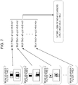
- Fig. 7 is a diagram for describing an example of a process performed by setting the filters as weak learners 1 to n, setting functions f1(x) to fn(x) outputting determination results regarding whether a detection target (for example, a finger) is included in each image region based on the feature amounts (x) obtained by the weak learners 1 to n corresponding to the filters, and calculating a score based on the determination results obtained by the plurality of weak learners.
- a detection target for example, a finger
- an and bn are coefficients (parameters). Further, g (x > thn) is a function of outputting a numeral value "1" indicating that a predetermined region is the detection target when the feature amount x is greater than the threshold value thn and is a function of outputting a numeral value "0" indicating that the predetermined region is not the detection target when the feature amount x is equal to or less than the threshold value thn.
- n is a filter discriminator
- the score F(x) is a sum of the determination results f1(x) to fn(x) of N weak learners.
- a detection target is considered to be present in an image.
- the output value of the score F(x) is equal to or less than the predetermined threshold value th, a detection target is considered not to be present in an image.
- the machine learning unit 113 performs, for example, a process of selecting the weak learner with high discrimination by inputting images classified into the following two kinds of categories as a plurality of pieces of learning image data, outputting the determination results to which the filters 1 to n described with reference to Figs. 4A to 5B is applied, and performing statistical learning based on the output results:
- These learning images are images in which attribute information (a label, a tag, or the like) indicating which image is present between the foregoing (A) and (B) is set.
- Each x of one rectangle illustrated in Fig. 8 indicates the feature amount x corresponding to a certain pixel of one image to which one filter is applied.
- the first to third differential filters illustrated in Figs. 4A, 4B , and Fig. 5A are used.
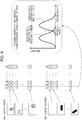
- Fig. 9 illustrates corresponding data of the feature amount (x) and a frequency when the filter f1 is applied to each learning image.
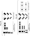
- Fig. 10A illustrates an example of frequency distribution data based on the weak learner (filter) with low discrimination.
- Fig. 10B illustrates an example of frequency distribution data based on the weak learner (filter) with high discrimination.
- a discrimination process with high reliability is realized by performing the processes of selecting only the weak learners (filters) with high discrimination based on the frequency distribution data and calculating the score described with reference to Fig. 7 from only the selected filters.
- Fig. 10C illustrates an example of frequency distribution data of the score calculated from only the selected plurality of weak learners (filters) with high discrimination.
- the threshold value of the score is decided by learning using, for example, a boosting or support vector and a statistical leaner such as a machine (support vector machine (SVM)).
- a boosting or support vector and a statistical leaner such as a machine (support vector machine (SVM)).
- SVM support vector machine
- the machine learning unit 113 performs such statistical learning to select the filters with the high discrimination.
- a recognition dictionary is generated by setting the parameters calculated through the learning process and data (tag) indicating the highness and lowness of the discrimination in each filter (weak learner), and then is stored in the recognition dictionary storage unit 114.
- a position determination process of determining whether the finger comes into contact with the board will be described later.
- the recognition processing unit 120 includes the image input unit 121, the feature amount extraction unit 122, and the specific object recognition unit 123.
- the recognition processing unit 120 inputs an analysis target image and performs a process of detecting a specific object and determining the position of the specific object.
- the recognition processing unit 120 performs the process of detecting the specific object and determining the position of the specific object using the recognition dictionary generated based on the learning data by the learning processing unit 110 and stored in the recognition dictionary storage unit 114.
- the image input unit 121 of the recognition processing unit 120 inputs analysis target images. That is, the analysis target images are an image photographed by the camera L11 and an image photographed by the camera R12 in the photography environment illustrated in Fig. 1A .
- the analysis target image is an image for which it is unclear whether the finger is included in the photographed image.
- the feature amount extraction unit 122 performs the feature amount extraction process to which the filters described with reference to Figs. 4A to 5B are applied, as in the feature amount extraction performed by the feature amount extraction unit 112 of the learning processing unit 110 described above.
- the filter weak learner
- the filter only the filter determined to have the high discrimination according to the learning result of the learning processing unit 110 is selected to perform the process.
- the filters are selected based on filter information (tag) stored in the recognition dictionary storage unit 114.
- the recognition processing unit 120 calculates the feature amount using the selected filter with the high discrimination, calculates the score, and performs the finger detection process and the process of determining whether the finger comes into contact with the board based on the value of the score.
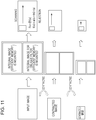
- Fig. 11 is a diagram schematically illustrating an order of an image searching process of the recognition processing unit 120.
- an integral image is generated as an intermediate image from an input image.
- the filter applying process described with reference to Fig. 6 may be performed directly on the input image. However, by generating the integral image based on the input image as the intermediate image and applying the filter to the integral image, a high-speed process can be performed.
- the feature amount extraction unit 122 of the recognition processing unit 120 generates two types of integral images for the vertical and horizontal rectangular filters and the oblique direction rectangular filters corresponding to the filters described with reference to Figs. 4A to 5B .
- the feature amount extraction unit 122 of the recognition processing unit 120 calculates the feature amount using the integral image generated from the input image and applying each filter on the integral image. That is, the process of calculating the feature amount (x) described above with reference to Fig. 6 is performed. Specifically, the integral image is scanned and the feature amount (x) is calculated at each scanned position (x, y) by applying the above-described expressions, (Expression 1) to (Expression 3).
- the filter to be applied is the selected filter (weak learner) having the high discrimination level.
- the specific object recognition unit 123 calculates the score by adding the feature amounts obtained by applying the plurality of selected filters (weak learners). This process is the process described above with reference to Fig. 7 .
- a target object i.e., the finger in the embodiment, is determined to be detected at the scanned position (x, y).
- the detection result can be negative (rejection), i.e., the result that the target object (finger) is not detected can be returned in some cases.
- the generation of the integral image and the calculation of the detected score may be configured to be repeated while changing scale conversion, i.e., the size of the input image.
- the integral image is recalculated when the scale conversion is performed on the input image.
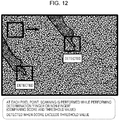
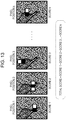
- FIG. 12 An example of the image scanning process is illustrated in Fig. 12 .
- the score corresponding to each pixel point is calculated by performing a scanning process sequentially in the horizontal direction from the upper right of the image, calculating the feature amount (x) based on the individual selected filter at each pixel point, and then adding the feature amounts (x) calculated based on the selected filters.
- the target object (finger) is determined to be detected.
- the score is calculated as the score corresponding to each pixel position.
- the target object (finger) may not be said to be detected in the image. That is, for example, when the plurality of high scores corresponding to the plurality of pixel positions according to the shape of the finger are not detected, the target object (finger) may not be said to be detected in the image.
- the specific object recognition unit 123 performs a total score evaluation process.
- Fig. 13 illustrates images indicating the filter application process at the pixel positions (pixel position 1 to k) set through the scanning process for the integral image and scores 1 to k calculated at the pixel positions calculated at the pixel positions.
- the scores increase at these pixel positions.
- the target object (finger) is determined to be detected.
- the specific object position determination process which is another process performed by the recognition processing unit 120, specifically, a process of determining whether the finger 30 illustrated in Figs. 1A and 1B comes into contact with the board 21, will be described.
- the learning processing unit 110 of the information processing device 100 illustrated in Fig. 3 generates the recognition dictionaries using the plurality of learning images.
- the flow of this process is the process described above.
- a learning target image to be subjected to the learning process is assumed to be a connected image obtained by connecting the L image which is an image photographed by the camera L11 and the R image which is an image photographed by the camera R12, as illustrated in Figs. 1A and 1B .
- the filter (weak learner) used to calculate the feature amount is assumed to be the separated filter illustrated in Fig. 5B .
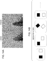
- FIG. 14A and 14B Examples of processing target images and examples of the filters are illustrated in Figs. 14A and 14B .
- Fig. 14A illustrates the processing target images, which become an image obtained by connecting the L image which is the image photographed by the camera L11 and the R image which is the image photographed by the camera R12, as illustrated in Figs. 1A and 1B .
- an LR-connected image illustrated in Fig. 14A is used.
- Fig. 14B illustrates the examples of the filters applied to calculation of the feature amount (x).
- the filters are the separated filters described above with reference to Fig. 5B and are the filters in which a white region and a black region are set to be separated.
- the drawing illustrates only the filters corresponding to a first differential form in which one white region and one black region are set. However, the filters of a second different form in which two white regions and one black region are set or the filters of a third differential form in which two white regions and two black regions are set may be used.
- the separated filter is applied.
- the plurality of LR-connected images are generated as the images of the following two categories and the learning process is performed:
- the feature amount extraction unit 112 of the learning processing unit 110 generates the LR connected image illustrated in Fig. 14A .
- a process of cutting out and connecting only image regions containing the finger to generate the connected image may be performed.
- the purpose of the learning process performed by the learning processing unit 110 is to determine parameters used in the feature amount calculation expression of the filters by selecting the filter appropriate for discriminating whether the finger comes into contact with the board. In order to efficiently perform such a process, the image regions are cut out and connected.
- Figs. 15A to 15C illustrate examples of the following images:
- the LR-connected image illustrated in Fig. 15C is an image generated by cutting out and connecting image regions of parts of the L photographed image and the R photographed image.
- the R image is cut out such that the finger tip of the finger and the base position of the finger contained in the R photographed image are cut out and are set at the center position of the cutout image.
- the L photographed image a region corresponding to the cutout position of the R photographed image is cut out.
- the LR-connected image is generated by performing such a process and connecting the cutout images.
- the filters can be evaluated and the parameters can be decided efficiently in the learning process in which it is necessary to process the plurality of LR-connected images.
- Figs. 16A and 16B are diagrams illustrating examples of the LR-connected image generated through the image cutout process and the image connection process and used to extract the feature amount.
- Examples 1 and 2 of both of the LR-connected images illustrated in Figs. 16A and 16B are examples of schematic integral images.
- the feature amount can also be calculated by generating the integral image described above with reference to Fig. 11 and performing the scanning process on the integral image.
- the feature amount extraction unit 112 of the learning processing unit 110 in Fig. 3 extracts the feature amount by performing the scanning process using such an LR-connected image. Further, the filter to be applied is the separated filter illustrated in Fig. 5B or Fig. 14B .
- the machine learning unit 113 of the learning processing unit 110 in Fig. 3 inputs the feature amount calculated by the feature amount extraction unit, evaluates the filter and decide the parameters.
- the plurality of LR-connected images are generated as the images of the following two categories and the learning process is performed:
- a process of selecting the weak learner with high discrimination is performed by inputting the images classified into the two kinds of categories, outputting the determination result to which the separated filter illustrated in Fig. 5B or 14B is applied, and performing statistical learning based on the output result.
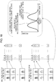
- Fig. 17 illustrates the following images as the examples of the learning images:
- These learning images are images in which attribute information (a label, a tag, or the like) indicating which image is present between the foregoing (A) and (B) is set.
- Each single rectangle illustrated in Fig. 17 indicates the feature amount x.
- the LR-connected image used as the learning image may be, for example, an average image generated by averaging a plurality of continuous photographed image frames obtained through a process of photographing a moving image.
- a process may be performed by performing such a process to generate the following plurality of learning images:
- the discrimination is high, a difference between the "finger contact LR-connected image" and the "finger non-contact LR-connected image” increases.
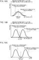
- Fig. 18 illustrates corresponding data of the feature amount (x) and a frequency when the filter f1 is applied to each learning image.
- Fig. 19A illustrates an example of frequency distribution data based on a weak learner (filter) with low discrimination.
- Fig. 19B illustrates an example of frequency distribution data based on the weak learner (filter) with high discrimination.
- a discrimination process with high reliability is realized by performing the processes of selecting only the weak learners (filters) with high discrimination based on the frequency distribution data and calculating the score described with reference to Fig. 7 from only the selected filters.
- Fig. 19C illustrates an example of frequency distribution data of the score calculated from only the selected plurality of weak learners (filters) with high discrimination.
- the threshold value of the score is decided by learning using, for example, a boosting or support vector and a statistical leaner such as a machine (support vector machine (SVM)).
- a boosting or support vector and a statistical leaner such as a machine (support vector machine (SVM)).
- SVM support vector machine
- the machine learning unit 113 performs such statistical learning to select the filters with the high discrimination and further determines the parameters.
- a recognition dictionary in which the parameters calculated through the learning process match data indicating the highness and lowness of the discrimination in each filter (weak learner) as filter information is generated, and then is stored in the recognition dictionary storage unit 114.
- the image input unit 121 of the recognition processing unit 120 inputs analysis target images, i.e., L and R images.
- the feature amount extraction unit 122 generates the LR-connected image using the input L and R images and calculates the feature amount.
- the feature amount extraction unit 122 When the feature amount extraction unit 122 extracts the feature amount from the connected image generated by connecting images photographed from different viewpoints, the feature amount extraction unit 122 performs the feature amount extraction process by applying the separated filter in which filter-formed regions are set to be separated and setting the filter regions forming the separated filter in the two images of the connected image.
- the specific object recognition unit 123 performs a specific object position determination process based on the feature amount extracted by the feature amount extraction unit.
- the feature amount extraction unit 122 performs the feature amount extraction process to which the separated filters described with reference to Fig. 5B or Fig. 14B are applied, as in the feature amount extraction performed by the feature amount extraction unit 112 of the learning processing unit 110 described above.
- the filter weak learner
- the filter only the filter determined to have the high discrimination according to the learning result of the learning processing unit 110 is used to perform the process.
- the process is performed using only the separated filter determined to have the high discrimination of the state (first state) in which the finger comes into contact with the board and the state (second state) in which the finger does not come into contact with the board.
- the filters are selected based on filter information (tag) stored in the recognition dictionary storage unit 114.
- the recognition processing unit 120 calculates the feature amount using the selected filter determined to have the high discrimination, calculates the score, and performs the finger detection process and the process of determining whether the finger comes into contact with the board based on the value of the score.
- the process performed by the recognition processing unit 120 is substantially the same process as the process described with reference to Fig. 11 and the subsequent drawings in the above description of the specific object detection process.
- this process differs in that the processing target image is the LR-connected image and the filter to be applied is the separated filter illustrated in Fig. 5B or Fig. 14B .
- the LR-connected image to be processed in the recognition process may be an LR image generated by connecting each photographed image frame photographed by each of the L and R cameras or may be an average image generated by averaging a plurality of continuous photographed image frames obtained through a process of photographing a moving image, as in the above-described learning image.
- the process may be performed by generating the LR-connected image generated based on an average image of the first to twentieth frames.
- a process performed by the recognition processing unit 120 will be described.
- the recognition processing unit 120 generates an integral image as an intermediate image from the LR-connected image in the order described above with reference to Fig. 11 .
- the feature amount extraction unit 122 of the recognition processing unit 120 calculates the feature amount using the integral image by applying each filter on the integral image. That is, for example, the feature amount calculation process described above with reference to Fig. 6 is performed. Specifically, the integral image is scanned and the feature amount (x) is calculated at each scanned position (x, y) by applying the above-described expressions, (Expression 1) to (Expression 3).
- the filter to be applied is the separated filter (weak learner) having the high discrimination level and selected in the learning process.
- the score is calculated by adding the feature amounts obtained by applying the plurality of selected filters (weak learners). This process is the same as the process described above with reference to Fig. 7 .
- the detection score When the detection score reaches a value equal to or greater than a preset threshold value, it is detected at the scanned position (x, y) that "the finger comes into contact with the board.”
- the detection result can be negative (rejection), i.e., the result that "the finger does not come into contact with the board” can be returned in some cases.
- the generation of the integral image and the calculation of the detected score may be configured to be repeated while changing scale conversion, i.e., the size of the input image.
- the integral image is recalculated when the scale conversion is performed on the input image.
- the score is calculated as a score corresponding to each pixel position.
- the specific object recognition unit 123 performs a total score evaluation process.
- the finger is determined to come into contact with the board.
- Figs. 20A and 20B are diagrams illustrating a difference between the LR-connected image when the finger comes into contact with the board and the LR-connected image when the finger does not come into contact with the board.
- Figs. 20A and 20B illustrate the following two average images:
- the LR-connected image for which the position of the finger in the R image is constant As illustrated in Fig. 20A , has the following characteristics. That is, since the positions of the L and R cameras are fixed even in images photographed at different timings, the parallax is constant. Therefore, on the LR-connected image, the position of the finger is set at substantially the same position. Accordingly, in an average image of L images, the contour of the finger is relatively clearly shown.
- the embodiment has been described in which, as the process of determining whether the finger comes into contact with the board, the feature amount is extracted by applying the separated filter using the LR-connected image which is the connected image of the images photographed from the plurality of different viewpoints.
- the embodiment is an embodiment in which a filter applied position is limited to an epipolar line set in the LR-connected image.
- the epipolar line is a line that is set as a search line of the same object position in two images from different viewpoints and is a line that is used for measurement of a subject distance or the like.
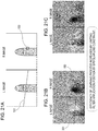
- an R image illustrated in Fig. 21A is assumed to be a criterion image
- points which are on an L image and correspond to certain points (feature points 150) on the R image are limited to an epipolar line 151 set in the L image. This is called epipolar constraint.
- the filter applied position is limited only to the epipolar line so that the filter applying process is performed.
- a point determined to be the feature point of an edge region or the like from an R image portion of the LR-connected image is selected and the epipolar line corresponding to the feature point is set on the L image.
- one filter region of the separated filter is set in the feature point of the R image and another filter region is set on the epipolar line on the L image.
- the feature amount is calculated by performing such setting and performing the filter applying process. Further, the feature amount at each pixel position may be calculated by sliding the filter on the epipolar line on the L image.
- the pixel region on which the filter applying process is performed can be limited by performing such a process, and thus a processing amount can be reduced and the high-speed process can be realized.
- Fig. 21B illustrates an example in which the filter applying process to which the epipolar constraint is applied is performed.
- Fig. 21C illustrates an example in which the filter applying process is performed without application of the epipolar constraint.
- the filter applying process is performed on the region of all of the pixels of the entire LR-connected image to calculate the feature amount corresponding to all of the pixels.
- the effective feature amount is estimated not to be obtained from most of the region.
- the filter applying process is performed within the range limited by the epipolar line on which the corresponding points of the R and L images are detected. Therefore, the processing time can be shortened and only the effective feature amounts can be selectively extracted.
- the feature amount is extracted using the LR-connected image which is the connected image of the images photographed from the plurality of different viewpoints by applying the separated filter described above in Fig. 5B or Fig. 14B .
- Various filters can be used as the separated filter applied to the process of determining whether the finger comes into contact with the board.
- the meanings of the feature amounts extracted from the images i.e., the extracted image characteristics, are different due to the forms of the filters.
- Fig. 22 illustrates a summary table of configuration examples of the separated filters and main image characteristics reflected to the feature amount data extracted by the separated filters.
- the separated filters illustrated in Fig. 22 are examples of applicable filters and filters with other various patterns can be applied.
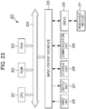
- a central processing unit (CPU) 201 functions as a data processing unit that performs various processes according to a program stored in a read-only memory (ROM) 202 or a storage unit 208.
- the CPU performs processes or the like according to the above-described embodiment.
- a random access memory (RAM) 203 appropriately stores, for example, data or a program executed by the CPU 201.
- the CPU 201, the ROM 202, and the RAM 203 are mutually connected by a bus 204.
- the CPU 201 is connected to an input/output interface 205 via the bus 204, and an input unit 206 including various switches, a keyboard, a mouse, or a microphone and an output unit 207 including a display or a speaker are connected to the input/output interface 205.
- the CPU 201 performs various processes in response to instructions input from the input unit 206 and outputs processing results to, for example, the output unit 207.
- the storage unit 208 connected to the input/output interface 205 includes, for example, a hard disk and stores various kinds of data or a program executed by the CPU 201.
- the communication unit 209 communicates with an external device via a network such as the Internet or a local area network.
- a drive 210 connected to the input/output interface 205 drives a removable medium 211 on which data is recorded or reproduced to record or reproduce data.
- a program executed by the CPU 201 can be recorded on the removable medium 211 serving as a package medium for supply.
- the series of processes described in the present specification can be executed by hardware, software, or a combination configuration of both the hardware and the software.
- a program recording a process sequence can be installed and executed in a memory in a computer embedded in dedicated hardware or a program can be installed and executed in a general computer capable of executing various processes.
- the program can be recorded in advance in a recording medium.
- the program can be installed in a computer from a recording medium and the program can also be received via a network such as a local area network (LAN) or the Internet and can be installed in a recording medium such as an internal hard disk.
- LAN local area network
- the Internet can be installed in a recording medium such as an internal hard disk.
- a system in the present specification refers to a logical collection of a plurality of devices and is not limited to a configuration in which constituent devices are present in the same casing.
Description
- The present disclosure relates to an information processing device, an information processing method, and a program, for example, to an information processing device, an information processing method, and a program analyzing presence or absence or the position of a specific object based on an image photographed by a camera.
- A distance analysis process may be used which uses a stereo camera as a system analyzing the position of a subject photographed in an image.
- This process may be a process of analyzing corresponding points of two images photographed from two different positions and calculating a distance (depth) from a camera to a subject based on information regarding the corresponding points.
- In the distance calculation process based on the corresponding points of two images, however, a calculation cost or a processing cost may increase. Therefore, unless a device having a sufficient capability to process data is used, a process delay occurs in some cases.
- A process using a feature amount may be used as a process of detecting a specific object, e.g., a human face or hand, from an image. This process may be a process of acquiring image data indicating a feature amount of a detection target in advance and detecting an image region similar to the feature amount in a photographed image. For example, when a human face is detected, image data indicating a feature amount of a human face is acquired in advance and an image region having the feature amount similar to the feature amount in a photographed image is determined as a face region.
- As the feature amount, for example, a feature amount which can be obtained by extracting an edge in an image is used. A target object may be detected by accumulating a plurality of pieces of feature amount data by a learning process performed in advance and comparing the accumulated learning data to an image region included in a photographed image (see
U.S. Patent Application Publication No. 2004/0013304 ,U.S. Patent Application Publication No. 2002/0102034 , andU.S. Patent No. 7,099,510 ). -
US 2013/279745 A1 discloses An image recognition device includes an image acquiring unit configured to acquire an image, and an object recognition unit configured to calculate gradient directions and gradient values of intensity of the image acquired by the image acquiring unit, to scan the gradient values of each acquired gradient direction with a window, to calculate a rectangular feature value, and to recognize a target object using a classifier based on the rectangular feature value. - Konrad Reif: "Automobilelektronik: Eine Einführung für Ingenieure",13 February 2012 (2012-02-13), pages 347-347, XPO55246089, DOI: 9783834886583 ISBN: 978-3-8348-8658-3 discloses that different camera images having an overlapping field of view but captured from different viewpoints can be used in order to obtain a panorama/ surround view image.
-
US2011157040 A1 discloses a touchpanel device which includes an approach determining unit configured to determine based on acquired image information whether an object has approached to or touched a touchscreen. - In the object detection process using the feature amount disclosed in the technologies of the related art, however, for example, a region similar to a specific feature amount can be detected in one image and an image region of a specific object can be specified, but a spatial position of the object is not determined.
- It is desirable to provide an information processing device, an information processing method, and a program performing, for example, a process of determining whether a specific object such as a human finger is included in an image based on an image photographed by a camera and a process of determining the position of the specific object.
- An information processing device, an information processing method, and a program is defined in the appended set of claims.
- According to a first embodiment of the present disclosure, there is provided an information processing device including a feature amount extraction unit configured to extract each feature amount from a connected image generated by connecting images photographed from different viewpoints; and a specific object recognition unit configured to perform a process of determining a position of a specific object based on the feature amount extracted by the feature amount extraction unit. The feature amount extraction unit performs a feature amount extraction process to which a separated filter in which filter-formed regions are set to be separated is applied.
- In the information processing device according to the embodiment of the present disclosure, the feature amount extraction unit may perform the feature amount extraction process by setting the separated filter regions forming the separated filter in two images of the connected image.
- In the information processing device according to the embodiment of the present disclosure, the feature amount extraction unit may extract the feature amount by selectively applying filters determined to have high discrimination in first and second states of the specific object in a learning process performed in advance.
- The information processing device according to the embodiment of the present disclosure may further include a learning processing unit configured to perform a process of determining the filter with high discrimination by inputting a plurality of connected images indicating the first and second states of the specific object and extracting the feature amounts to which separated filters with different formats are applied.
- In the information processing device according to the embodiment of the present disclosure, the specific object recognition unit may calculate a score by adding the feature amounts corresponding to the different separated filters and extracted by the feature amount extraction unit and perform the process of determining the position of the specific object based on the added score.
- In the information processing device according to the embodiment of the present disclosure, the specific object recognition unit may calculate scores corresponding to pixels and obtained by adding the feature amounts corresponding to the pixels corresponding to the different separated filters and extracted by the feature amount extraction unit and perform the process of determining the position of the specific object based on a total score obtained by further adding the calculated scores corresponding to the pixels.
- In the information processing device according to the embodiment of the present disclosure, the feature amount extraction unit may calculate the feature amount as an index value used to distinguish a first state in which a finger, which is the specific object, comes into contact with a board from a second state in which the finger does not come into contact with the board. Based on the feature amount extracted by the feature amount extraction unit, the specific object recognition unit may perform a process of determining whether the finger which is the specific object comes into contact with the board.
- In the information processing device according to the embodiment of the present disclosure, the feature amount extraction unit may further extract the feature amount as the index value used to determine whether the specific object is present in an image. Based on the feature amount extracted by the feature amount extraction unit, the specific object recognition unit may perform a specific object detection process of determining whether the specific object is present or absent.
- In the information processing device according to the embodiment of the present disclosure, the separated filter may be a filter in which filter regions with different luminance are set to be separated.
- In the information processing device according to the embodiment of the present disclosure, the feature amount extraction unit may extract the feature amount by setting the separated filter on an epipolar line corresponding to a feature point of one image of the connected image and the feature point on the other image of the connected image.
- According to a second embodiment of the present disclosure, there is provided an information processing method performed in an information processing device. The method includes extracting, by a feature amount extraction unit, a feature amount from a connected image generated by connecting images photographed from different viewpoints; and performing, by a specific object recognition unit, a process of determining a position of a specific object based on the feature amount extracted by the feature amount extraction unit. The feature amount extraction unit performs a feature amount extraction process to which a separated filter in which filter-formed regions are set to be separated is applied.
- According to a third embodiment of the present disclosure, there is provided a program causing an information processing device to perform information processing. The program causes a feature amount extraction unit to extract a feature amount from a connected image generated by connecting images photographed from different viewpoints; a specific object recognition unit to perform a process of determining a position of a specific object based on the feature amount extracted by the feature amount extraction unit; and the feature amount extraction unit to perform a feature amount extraction process to which a separated filter in which filter-formed regions are set to be separated is applied.
- The program according to an embodiment of the present disclosure is a program which can be supplied to an information processing device or a computer system capable of executing various program codes by a communication medium or a storage medium supplying the program in a computer-readable format. By supplying the program in the computer-readable format, a process is realized according to the program on the information processing device or the computer system.
- The other purposes, characteristics, and advantages of an embodiment of the present disclosure will be apparent from the more detailed description based on embodiments of the present disclosure to be described and the appended drawings. A system in the present specification refers to a logical collection of a plurality of devices and is not limited to a configuration in which constituent devices are present in the same casing.
- According to the configuration of the embodiments of the present disclosure, a device and a method are realized in which the specific object position determination process is performed based on the feature amount extracted from the connected image of the images photographed from the different viewpoints.
- Specifically, each feature amount is extracted from a connected image generated by connecting images photographed from different viewpoints and a process of determining a position of a specific object is performed based on the feature amount extracted by the feature amount extraction unit. A feature amount extraction unit performs a feature amount extraction process to which a separated filter in which filter-formed regions are set to be separated is applied and performs the feature amount extraction process by setting the separated filter regions forming the separated filter in two images of the connected image. A specific object recognition unit performs a specific object position determination process based on a score by adding the feature amounts corresponding to the different separated filters and extracted by the feature amount extraction unit.
- In the configuration, the device and the method are realized in which the specific object position determination process is performed based on the feature amount extracted from the connected image of the images photographed from the different viewpoints.
- The advantages described in the present specification are merely exemplary and are not limited, and additional advantages may be obtained.
- Embodiments of the invention will now be described with reference to the accompanying drawings, throughout which like parts are referred to by like references, and in which:
-
Figs. 1A and 1B are diagrams for describing an overview of a process performed by an information processing device according to an embodiment of the present disclosure; -
Fig. 2 is a flowchart illustrating a sequence of a process performed by the information processing device according to the embodiment of the present disclosure; -
Fig. 3 is a diagram for describing the configuration and a process of the information processing device according to the embodiment of the present disclosure; -
Figs. 4A and 4B are diagrams for describing a filter applied to feature amount extraction; -
Figs. 5A and 5B are diagrams for describing a filter applied to the feature amount extraction; -
Fig. 6 is a diagram for describing a feature amount extraction process; -
Fig. 7 is a diagram for describing a score calculation process; -
Fig. 8 is a diagram for describing a learning process for object detection; -
Fig. 9 is a diagram for describing the learning process for the object detection; -
Figs. 10A to 10C are diagrams for describing the learning process for the object detection; -
Fig. 11 is a diagram for describing the feature amount extraction process; -
Fig. 12 is a diagram for describing the feature amount extraction process; -
Fig. 13 is a diagram for describing a total score calculation process; -
Figs. 14A and 14B are diagrams for describing images and filters applied to a specific object position determination process; -
Figs. 15A to 15C are diagrams for describing an image cutout process and a process of generating an LR-connected image; -
Figs. 16A and 16B are diagrams for describing examples of the LR-connected image; -
Fig. 17 is a diagram for describing a learning process for object position determination; -
Fig. 18 is a diagram for describing the learning process for the object position determination; -
Figs. 19A to 19C are diagrams for describing the learning process for the object position determination; -
Figs. 20A and 20B are diagrams for describing a difference between a contact image and a non-contact image in which a finger comes into contact with a board; -
Figs. 21A to 21C are diagrams for describing limitation of a filter application region to which an epipolar line is applied; -
Fig. 22 is a diagram for describing characteristics and types of separated filters; and -
Fig. 23 is a diagram for describing an example of the configuration of an information processing device. - Hereinafter, the details of an information processing device, an information processing method, and a program will be described with reference to the drawings and the description thereof will be made in the following items.
- 1. Overview of Process Performed by Information Processing Device According to Embodiment of the Present Disclosure
- 2. Configuration and Process of Information Processing Device
- 3. Process Performed by Each Unit Included in Information Processing Device
- 3-1. Process Performed by Feature Amount Extraction Unit of Learning Processing Unit
- 3-2. Process Performed by Machine Learning Unit
- 3-3. Process Performed by Recognition Processing Unit
- 4. Process of Determining Position of Specific Object
- 4-1. Process Performed by Learning Processing Unit
- 4-2. Process Performed by Recognition Processing Unit
- 5. Embodiment in Which Filter Application Position Is Limited
- 6. Characteristics and Type of Separated Filter
- 7. Example of Configuration of Information Processing Device
- 8. Conclusion of Configuration According to Embodiment of the Present Disclosure
- First, an overview of a process performed by the information processing device according to an embodiment of the present disclosure will be described with reference to
Figs. 1A and 1B and the subsequent drawings. - The information processing device according to the embodiment of the present disclosure inputs images photographed by cameras installed at a plurality of different positions and performs each of the following processes based on the images photographed by the cameras:
- (a) a "specific object detection process" of determining whether a specific object is included in a photographed image; and
- (b) a "specific object position determination process" of determining the position of the specific object detected in the foregoing process (a).
- Each of the processes (a) and (b) are performed.
- The following embodiment will be described as an embodiment in which a specific object on which the detection process and the position determination process are performed is a
human finger 30 illustrated inFig. 1A . - An embodiment will be described in which the specific object position determination process is performed as a process of determining two states regarding whether the
finger 30 comes into contact with (touches) aboard 21. -
Fig. 1A is a diagram illustrating an example of an image photography environment. -
Fig. 1A illustrates a state in which thehuman finger 30 is present on theboard 21 and thefinger 30 comes into contact with (touches) theboard 21. - The
finger 30 is moved frequently and does not come into contact with theboard 21 in some cases or is distant from theboard 21 and is not present on theboard 21 in some cases. - That is, as the states of the
finger 30, there are the following three kinds of states: - (state 1) a state in which the
finger 30 comes into contact withboard 21; - (state 2) a state in which the
finger 30 is present above theboard 21 and does not come into contact with theboard 21; and - (state 3) a state in which the
finger 30 does not come into contact with theboard 21 and is not present above theboard 21. - The information processing device according to an embodiment of the present disclosure determines the foregoing three states based on images photographed by two cameras illustrated in
Figs. 1A and 1B , i.e., a camera L11 and a camera R12. - The camera L11 is fixed at a position on the upper left side when viewed from the center of the
board 21 and photographs a plane of theboard 21 from the upper left side. - On the other hand, the camera R12 is fixed at a position on the upper right side when viewed from the center of the
board 21 and photographs the plane of theboard 21 from the upper right side. - When the
finger 30 is present above theboard 21, an image including thefinger 30 is photographed from each of the upper left side and the upper right side. - An example of the image photographed by each camera is illustrated in
Fig. 1B . - An
L image 51 is an image photographed by the camera L11. - An
R image 52 is an image photographed by the camera R12. - The examples of the images are the photographed images in the state in which the
finger 30 comes into contact with theboard 21. - When the
finger 30 does not come into contact with theboard 21 or thefinger 30 is not present above theboard 21, images different from the images illustrated inFig. 1B are photographed. - The images photographed by the camera L11 and the camera L12 may be still images or moving images. When the images are still images, the state of the
finger 30 is determined among the foregoing (state 1) to (state 3) using the two photographed still images. - When the photographed images are moving images, the state of the
finger 30 is determined among the foregoing (state 1) to (state 3), for example, in photography frame units or predefined predetermined frame intervals. - Next, a process sequence performed by the information processing device according to an embodiment of the present disclosure will be described with reference to the flowchart illustrated in
Fig. 2 . - The information processing device according to an embodiment of the present disclosure inputs, for example, the images photographed by the camera L11 and the camera R12 set at two different positions illustrated in
Figs. 1A and 1B and performs a process of determining a state of thefinger 30 among the above-described states, i.e., the following three states based on these images: - (state 1) a state in which the
finger 30 comes into contact withboard 21; - (state 2) a state in which the
finger 30 is present above theboard 21 and does not come into contact with theboard 21; and - (state 3) a state in which the
finger 30 does not come into contact with and is not present above theboard 21. - The process of each step of the flow illustrated in
Fig. 2 will be described. - First, the information processing device performs a finger detection process of determining whether the finger is included in the photographed image. This process is performed using only one image between the
L image 51 and theR image 52 illustrated inFig. 1B . - In the finger detection process, learning data indicating feature amounts accumulated in advance is used. A specific example of this process will be described later.
- In step S102, the information processing device determines whether the finger is detected from the photographed image.
- When the finger is not detected, the process proceeds to step S103. An analysis result indicating that the finger is not detected is output, and the process proceeds to step S108.
- An output destination of the analysis result is a data processing unit that performs a process according to the analysis result, and may be a data processing unit in the information processing device or may be an external device connected to the information processing device.
- When it is determined in step S102 that the finger is detected in the photographed image, the process proceeds to step S104.
- In step S104, a contact determination process is performed as a finger position detection process to determine whether the finger comes into contact with (touches) the board.
- In the contact determination process, the
L image 51 and theR image 52 illustrated inFig. 1B , i.e., the plurality of images photographed from different viewpoints, are used. - In the contact determination process, the learning data indicating feature amounts accumulated in advance is also used. A specific example of this process will be described later.
- In step S105, the information processing device determines whether the finger detected from the photographed image comes into contact with the board. When it is determined that the finger does not come into contact with the board, the process proceeds to step S106. An analysis result indicating that the finger does not come into contact with the board is output and the process proceeds to step S108.
- Conversely, when it is determined that the finger comes into contact with the board, the process proceeds to step S107. An analysis result indicating that the finger comes into contact with the board is output and the process proceeds to step S108.
- An output destination of the analysis result is a data processing unit that performs a process according to the analysis result, and may be a data processing unit in the information processing device or may be an external device connected to the information processing device.
- Next, in step S108, the information processing device determines whether the analysis process ends. When an image to be analyzed is not input, it is determined that the process ends. For example, when the analysis is continuously performed at predefined frame intervals while photographing a moving image, the process according to the flow illustrated in
Fig. 2 is performed repeatedly at predetermined frame intervals. In this case, the determination of step S108 is NO, and thus the process returns to step S101 and the analysis process of step S101 and the subsequent steps is repeatedly performed on a new input image. - In this way, the information processing device according to an embodiment of the present disclosure performs the object detection process based on one photographed image, applies an image photographed continuously from a different viewpoint, and performs the object position determination process.
- In the embodiment described herein, the object detection process is performed as a finger detection process and the object position determination process is performed as a process of determining two states regarding whether the finger comes into contact with the board.
- Next, an example of the configuration of the information processing device according to an embodiment of the present disclosure will be described.
- The example of the configuration of the information processing device according to an embodiment of the present disclosure is illustrated in
Fig. 3 . Aninformation processing device 100 includes alearning processing unit 110 and arecognition processing unit 120. - The
learning processing unit 110 includes animage input unit 111, a featureamount extraction unit 112, amachine learning unit 113, and a recognitiondictionary storage unit 114. - The
learning processing unit 110 inputs a plurality of images as learning images and therecognition processing unit 120 generates a recognition dictionary used in a process of discriminating presence or absence of a specific object or the position of the specific object from the image based on the learning images. The generated recognition dictionary is stored in the recognitiondictionary storage unit 114. - On the other hand, the
recognition processing unit 120 includes animage input unit 121, a featureamount extraction unit 122, and a specificobject recognition unit 123. - The
recognition processing unit 120 inputs an analysis target image and performs a process of detecting a specific object and determining the position of the specific object. Therecognition processing unit 120 performs the process of detecting the specific object and determining the position of the specific object using the recognition dictionary generated based on the learning data by thelearning processing unit 110 and stored in the recognitiondictionary storage unit 114. - The process according to the flowchart described with reference to
Fig. 2 corresponds to the process performed by therecognition processing unit 120. - The
information processing device 100 illustrated inFig. 3 performs the following two processes, as described above with reference to the flow illustrated inFig. 2 . - (process 1) an object detection process of determining whether a finger is included in an image; and
- (process 2) an object position determination process (contact determination process) of determining whether the detected finger comes into contact with the board.
- The
learning processing unit 110 of theinformation processing device 100 generates recognition dictionaries as learning data applied to the foregoing (process 1) and (process 2). - The
recognition processing unit 120 performs each of the following process by individually applying the recognition dictionaries corresponding to the foregoing (process 1) and (process 2) generated by the learning processing unit, i.e.: - (process 1) the object detection process of determining whether a finger is included in an image; and
- (process 2) the object position determination process (contact determination process) of determining whether the detected finger comes into contact with the board.
- Hereinafter, the processes performed by the processing units of the
information processing device 100 illustrated inFig. 3 will be described in sequence. - First, a process performed by the feature
amount extraction unit 112 in thelearning processing unit 110 of theinformation processing device 100 illustrated inFig. 3 will be described. - The
learning processing unit 110 inputs the plurality of photographed images as learning images from theimage input unit 111. - The learning images are, for example, a plurality of images photographed in the photography environment described with reference to
Fig. 1A . The learning images include a plurality of images in the following states: - (state 1) the state in which the
finger 30 comes into contact with theboard 21; - (state 2) the state in which the
finger 30 is present above theboard 21 and does not come into contact with theboard 21; and - (state 3) the state in which the
finger 30 does not come into contact with and is not present above theboard 21. - In each of the learning images input in the learning process, attribute information (a label, a tag, or the like) indicating in which state each image is among the foregoing states is set.
- The feature
amount extraction unit 112 extracts a feature amount included in the learning image input from theimage input unit 111. In the feature amount extraction, various filters are used. Examples of rectangular filters applied to the feature amount extraction are illustrated inFigs. 4A to 5B . - First differential filters illustrated in
Fig. 4A are filters appropriate for a process of extracting a pixel region that has a feature in which a change direction is from white to black or from black to white in an image from an input image. - Vertical or horizontal direction filters can efficiently extract a pixel region when the change direction from white to black or from black to white is a vertical or horizontal direction. Oblique direction filters can efficiently extract a pixel region when the change direction from white to black or from black to white is an oblique direction.
- Second differential filters illustrated in
Fig. 4B are filters appropriate for a process of extracting a pixel region having a feature in which a change direction is white/black/white or black/white/black in an image from an input image. - Vertical or horizontal direction filters can efficiently extract a pixel region when the change direction is a vertical or horizontal direction. The oblique direction filters can efficiently extract a pixel region when the change direction is an oblique direction.
- Third differential filters illustrated in
Fig. 5A are filters appropriate for a process of extracting a pixel region having a feature in which a change direction is white/black/white/black or black/white/black/white in an image from an input image. - Vertical or horizontal direction filters can efficiently extract a pixel region when the change direction is a vertical or horizontal direction. The oblique direction filters can efficiently extract a pixel region when the change direction is an oblique direction.
- The rectangular filters illustrated in
Figs. 4A, 4B , and5A are known filters that are used to extract a feature amount in the related art. - Separated filters illustrated in
Fig. 5B are filters that are not known filters, but are devised as filters used for the object position determination process performed by the information processing device according to an embodiment of the present disclosure. - The separated filters are filters that are used to determine the position of the
finger 30 illustrated inFigs. 1A and 1B , specifically, to determine whether thefinger 30 comes into contact with theboard 21. - The separated filters illustrated in
Fig. 5B have a feature in which white and black patterns are set to be separate. This feature is different from that of the first to third differential filters illustrated inFigs. 4A, 4B , and5A . - A finger position determination process to which the separated filters illustrated in
Fig. 5B are applied will be described in detail later. - An example of feature amount extraction to which the filters are applied and which are performed by the feature
amount extraction unit 112 in thelearning processing unit 110 of theinformation processing device 100 illustrated inFig. 3 will be described with reference toFig. 6 . -
Fig. 6 is a diagram for describing an example of a process of extracting a pixel region having the same change region from images by applying afilter 130 which is shown in the upper left end of the first differential filters illustrated inFig. 4A and in which the change direction is the horizontal direction from black to white. - Part (A) of
Fig. 6 illustrates an input image. Here, the input image is a learning image. - Part (B) of
Fig. 6 illustrates an image which can be obtained by performing filter calculation to which thefilter 130 is applied which is shown in the upper left end of the first differential filters illustrated inFig. 4A and in which the change direction is the horizontal direction from black to white. - The filter calculation is performed according to an expression below, as illustrated.

- In (Expression 1) above, Gd,θ is a d-th differential function of a Gauss function G corresponding to each filter described with reference to
Figs. 4A to 5B . Here, d corresponds to an order described with reference toFigs. 4A to 5B and θ corresponds to the angle of the filter, i.e., a set angle of the filter at a vertical or horizontal angle (0° or 90°), an oblique angle (45° or 135°), or the like described with reference toFigs. 4A to 5B . - Further, (xi, yi) in I (xi, yi, si) indicates the position of a pixel, si means the scale of an image, and i is a scale discriminator of an image to be applied.
- I (xi, yi, si) presents a pixel value at the pixel position (xi, yi) of an image with the scale si, e.g., luminance.
- (Expression 1) above is an expression by which convolution calculation of the filter defined by Gd,θ and each pixel of the image is performed.
- The example illustrated in
Fig. 6 is an execution example of filter calculation to which thefilter 130, which is shown in the upper left end of the first differential filters illustrated inFig. 4A and in which the change direction is the horizontal direction from black to white, is applied. - Through the filter calculation, the pixel value of the input image illustrated in part (A) of
Fig. 6 is converted into an image illustrated in part (B) ofFig. 6 . - Part (C) of
Fig. 6 illustrates an image obtained by performing a calculation process of equalizing a pattern changed from black to white and a pattern conversely changed from white to black in the right direction corresponding to thefilter 130 illustrated inFig. 4A . Through this process, extraction of a feature pattern which is not changed for, for example, background luminance is realized. - The filter calculation applied to the generation of the image is a calculation expressed by an expression below.

- (Expression 2) above corresponds to a process of calculating the absolute value of (Expression 1) described above.
- Part (D) of
Fig. 6 illustrates an image subjected to a process of smoothing a result obtained by (Expression 2) above in a pixel region of a predetermined range of the image illustrated in part (C) ofFig. 6 in order to improve resistance to deviation or the like of a pixel position. - The filter calculation applied to the generation of the image is a calculation expressed by an expression below.

- For example, a value which can be obtained by (Expression 3) above is a feature amount (x) obtained based on a filter defined by Gd,θ.
- The example illustrated in
Fig. 6 is an example of a feature amount calculation process to which thefilter 130, which is shown in the upper left end of the first differential filters illustrated inFig. 4A and in which the change direction is the horizontal direction from black to white, is applied. The value of the feature amount (x) increases in a pixel region similar to the pattern of thefilter 130. - The feature amount (x) is calculated as a value corresponding to each pixel.
- The same process is also performed on the other filters, the feature amount (x) corresponding to each filter is extracted, and the extraction result is output to the
machine learning unit 113 illustrated inFig. 3 . - Next, a process performed by the
machine learning unit 113 in thelearning processing unit 110 of theinformation processing device 100 illustrated inFig. 3 will be described. - Each of the filters illustrated in
Figs. 4A to 5B becomes a weak learner (WL). The weak learner determines whether an object is detected based on rectangular characteristics obtained by superimposing the filter on a search region, e.g., whether a difference (feature amount x) between a sum of the luminance values in a region corresponding to a black rectangle and a sum of the luminance values in a region corresponding to a white rectangle is greater than a threshold value (th). - In the process according to an embodiment of the present disclosure, position determination (contact determination) of determining whether a finger comes into contact with a board is also performed as a specific object (finger) detection process and a specific object (finger) position determination process.
- In the object detection process, whether the specific object is detected is determined based on whether the feature amount (x) obtained through the filter application is greater than the threshold value.
- In the object position determination process (contact determination process), whether the object (finger) comes into contact with the board is determined based on whether the feature amount (x) obtained through the filter application is greater than the threshold value.
- In the application of the rectangular filters of the black and white patterns illustrated in
Figs. 4A to 5B , a finger region can be determined from an input image at a certain probability based on the rectangular characteristics, for example, using the learning result that the luminance value of the finger region is lower than that of the background. - A sufficient discriminative capability may not be obtained by only an individual weak learner, but a learner having stronger discrimination can be constructed by linearly combining the discrimination results of a plurality of weak learners.
- One of the processes performed by the
machine learning unit 113 is to generate a stronger learner by integrating the feature amount extraction results obtained by the weak learners corresponding to the filters and to generate selection information (score) of a feature amount optimum for detection or position determination of the specific object (finger) in therecognition processing unit 120. - This process will be described with reference to
Fig. 7 . - An example of a process when the object detection process of determining whether the finger is included in an image is performed will be described with reference to
Fig. 7 and the subsequent drawings. The position determination process of determining whether the finger comes into contact with the board will be described later. -
Fig. 7 is a diagram for describing an example of a process performed by setting the filters asweak learners 1 to n, setting functions f1(x) to fn(x) outputting determination results regarding whether a detection target (for example, a finger) is included in each image region based on the feature amounts (x) obtained by theweak learners 1 to n corresponding to the filters, and calculating a score based on the determination results obtained by the plurality of weak learners. - The function fn1(x) outputting the determination results regarding whether the detection target (for example, a finger) is included in each image region based on the feature amounts (x) obtained by the
weak learners 1 to n corresponding to the filters is expressed by an expression (Expression 4) below:
- In Expression (4), an and bn are coefficients (parameters). Further, g (x > thn) is a function of outputting a numeral value "1" indicating that a predetermined region is the detection target when the feature amount x is greater than the threshold value thn and is a function of outputting a numeral value "0" indicating that the predetermined region is not the detection target when the feature amount x is equal to or less than the threshold value thn.
- Here, n is a filter discriminator.
- When a value calculated by (Expression 4) above is "fn(x) = an + bn," the predetermined region is determined to be the detection target. When a value calculated by (Expression 4) above is "fn(x) = bn," the predetermined region is determined not to be the detection target.
- An added value of the determination results fn(x) of the weak learners is assumed to be a score F(x).
- The score F(x) is expressed by, for example, the following expression (Expression 5):

- That is, the score F(x) is a sum of the determination results f1(x) to fn(x) of N weak learners. When the value of the score F(x) is greater than a predetermined threshold value th, a detection target is considered to be present in an image. When the output value of the score F(x) is equal to or less than the predetermined threshold value th, a detection target is considered not to be present in an image.
- The
machine learning unit 113 performs, for example, a process of selecting the weak learner with high discrimination by inputting images classified into the following two kinds of categories as a plurality of pieces of learning image data, outputting the determination results to which thefilters 1 to n described with reference toFigs. 4A to 5B is applied, and performing statistical learning based on the output results: - an image including the finger; and
- an image including no finger.
- These processes will be described with reference to
Fig. 8 . - In
Fig. 8 , as examples of the learning images, the following images are illustrated: - Part (A) a "finger presence image" in which a finger which is a discrimination target object is included in a photographed image; and
- Part (B) a "finger absence image" in which a finger which is a discrimination target object is not included in a photographed image.
- These learning images are images in which attribute information (a label, a tag, or the like) indicating which image is present between the foregoing (A) and (B) is set.
- For each of these images, the feature amount (x) obtained by applying the filters f1 to fn (= the
weak learners 1 to n) described with reference toFigs. 4A to 5B is calculated. Each x of one rectangle illustrated inFig. 8 indicates the feature amount x corresponding to a certain pixel of one image to which one filter is applied. - In the object detection process, the first to third differential filters illustrated in
Figs. 4A, 4B , andFig. 5A are used. - In the object position determination process, the separated filters described in
Fig. 5B are used. - The value of the feature amount x calculated through a filter applying process is a value that differs according to the discrimination of the filters f1 to fn (= the
weak learners 1 to n). When the discrimination is high, a difference between the finger presence image and the finger absence image increases. -
Fig. 9 illustrates corresponding data of the feature amount (x) and a frequency when the filter f1 is applied to each learning image. - As shown in the frequency distribution data, when there is discrimination to some extent, different mounts are formed between a frequency distribution of finger presence image data and a frequency distribution of finger absence image data.
- However, the distributions become different according to the filters to be applied.
-
Fig. 10A illustrates an example of frequency distribution data based on the weak learner (filter) with low discrimination. -
Fig. 10B illustrates an example of frequency distribution data based on the weak learner (filter) with high discrimination. - Thus, when the weak learner (filter) with low discrimination is applied, it is difficult to distinguish the finger presence image from the finger absence image. When the weak learner (filter) with high discrimination is applied, it is easy to distinguish the finger presence image from the finger absence image.
- A discrimination process with high reliability is realized by performing the processes of selecting only the weak learners (filters) with high discrimination based on the frequency distribution data and calculating the score described with reference to
Fig. 7 from only the selected filters. -
Fig. 10C illustrates an example of frequency distribution data of the score calculated from only the selected plurality of weak learners (filters) with high discrimination. - The threshold value of the score is decided by learning using, for example, a boosting or support vector and a statistical leaner such as a machine (support vector machine (SVM)).
- The
machine learning unit 113 performs such statistical learning to select the filters with the high discrimination. - Even for the parameters an, bn, and thn used in the function fn1(x) outputting the determination result by each filter (weak learner) described above with reference to
Fig. 7 , i.e., the following expression, an optimum value used to set a high discrimination level is calculated by the statistical learning:
- A recognition dictionary is generated by setting the parameters calculated through the learning process and data (tag) indicating the highness and lowness of the discrimination in each filter (weak learner), and then is stored in the recognition
dictionary storage unit 114. - Next, a process performed by the
recognition processing unit 120 of theinformation processing device 100 illustrated inFig. 3 will be described. - A specific object detection process of determining whether the finger is included in an image will be first described.
- A position determination process of determining whether the finger comes into contact with the board will be described later.
- The
recognition processing unit 120 includes theimage input unit 121, the featureamount extraction unit 122, and the specificobject recognition unit 123. - The
recognition processing unit 120 inputs an analysis target image and performs a process of detecting a specific object and determining the position of the specific object. Therecognition processing unit 120 performs the process of detecting the specific object and determining the position of the specific object using the recognition dictionary generated based on the learning data by thelearning processing unit 110 and stored in the recognitiondictionary storage unit 114. - The process according to the flowchart described with reference to
Fig. 2 corresponds to the process performed by therecognition processing unit 120. - The
image input unit 121 of therecognition processing unit 120 inputs analysis target images. That is, the analysis target images are an image photographed by the camera L11 and an image photographed by the camera R12 in the photography environment illustrated inFig. 1A . - Unlike the learning image, the analysis target image is an image for which it is unclear whether the finger is included in the photographed image.
- As described above with reference to
Fig. 2 , only one of the L image and the R image is used in the finger detection process of detecting whether there is the finger, and two images of the L image and the R image are used in the process of determining whether the finger comes into contact with the board. - The feature
amount extraction unit 122 performs the feature amount extraction process to which the filters described with reference toFigs. 4A to 5B are applied, as in the feature amount extraction performed by the featureamount extraction unit 112 of thelearning processing unit 110 described above. - However, as the filter (weak learner) to be applied to the feature
amount extraction unit 122 of therecognition processing unit 120, only the filter determined to have the high discrimination according to the learning result of thelearning processing unit 110 is selected to perform the process. - The filters are selected based on filter information (tag) stored in the recognition
dictionary storage unit 114. - Even for the parameters an, bn, and thn in the calculation expression of the feature amount (x) calculated using each filter (weak learner), i.e., the following expression, the values decided through the learning process of the
learning processing unit 110 described above and stored in the recognitiondictionary storage unit 114 are used:
- The
recognition processing unit 120 calculates the feature amount using the selected filter with the high discrimination, calculates the score, and performs the finger detection process and the process of determining whether the finger comes into contact with the board based on the value of the score. - Hereinafter, a process performed by the
recognition processing unit 120 will be described with reference to the drawing. -
Fig. 11 is a diagram schematically illustrating an order of an image searching process of therecognition processing unit 120. - First, an integral image is generated as an intermediate image from an input image.
- The filter applying process described with reference to
Fig. 6 may be performed directly on the input image. However, by generating the integral image based on the input image as the intermediate image and applying the filter to the integral image, a high-speed process can be performed. - Further, the process of generating the integral image and the high-speed process of calculating the feature amount using the integral image are disclosed in Japanese Unexamined Patent Application Publication No.
2011-180792 - For vertical and horizontal rectangular filters and oblique direction rectangular filters, a method of generating the integral image differs. The feature
amount extraction unit 122 of therecognition processing unit 120 generates two types of integral images for the vertical and horizontal rectangular filters and the oblique direction rectangular filters corresponding to the filters described with reference toFigs. 4A to 5B . - The feature
amount extraction unit 122 of therecognition processing unit 120 calculates the feature amount using the integral image generated from the input image and applying each filter on the integral image. That is, the process of calculating the feature amount (x) described above with reference toFig. 6 is performed. Specifically, the integral image is scanned and the feature amount (x) is calculated at each scanned position (x, y) by applying the above-described expressions, (Expression 1) to (Expression 3). - Here, the filter to be applied is the selected filter (weak learner) having the high discrimination level.
- The specific
object recognition unit 123 calculates the score by adding the feature amounts obtained by applying the plurality of selected filters (weak learners). This process is the process described above with reference toFig. 7 . - By using the integral image, rectangular characteristics can be calculated at high speed at each scanned position.
- When the detection score reaches a value equal to or greater than a preset threshold value, a target object, i.e., the finger in the embodiment, is determined to be detected at the scanned position (x, y).
- Depending on the maximum detected score obtained by scanning the image, the detection result can be negative (rejection), i.e., the result that the target object (finger) is not detected can be returned in some cases. Further, the generation of the integral image and the calculation of the detected score may be configured to be repeated while changing scale conversion, i.e., the size of the input image.
- When the scale conversion is performed on the initially calculated integral image, a window with any size can be searched for. However, when the scale conversion is performed on the integral image, a calculation amount increases and the advantage of speeding up the process using the integral image is cancelled. Accordingly, in the example illustrated in
Fig. 11 , the integral image is recalculated when the scale conversion is performed on the input image. - An example of the image scanning process is illustrated in
Fig. 12 . - The score corresponding to each pixel point is calculated by performing a scanning process sequentially in the horizontal direction from the upper right of the image, calculating the feature amount (x) based on the individual selected filter at each pixel point, and then adding the feature amounts (x) calculated based on the selected filters.
- When the calculated score exceeds a predefined threshold value, the target object (finger) is determined to be detected.
- As illustrated in
Fig. 12 , the score is calculated as the score corresponding to each pixel position. However, for example, even when the score is high at only one pixel position, the target object (finger) may not be said to be detected in the image. That is, for example, when the plurality of high scores corresponding to the plurality of pixel positions according to the shape of the finger are not detected, the target object (finger) may not be said to be detected in the image. - Accordingly, in order to finally determine whether the finger is detected, it is necessary to evaluate the total scores of the plurality of pixel positions.
- The specific
object recognition unit 123 performs a total score evaluation process. - An example of the total score evaluation process will be described with reference to
Fig. 13 . -
Fig. 13 illustrates images indicating the filter application process at the pixel positions (pixel position 1 to k) set through the scanning process for the integral image andscores 1 to k calculated at the pixel positions calculated at the pixel positions. - When the finger is detected, the scores increase at these pixel positions.
- A total score which is a total evaluation value serving as a final index value used to determine whether the target object (finger) included in the image is calculated as an added value of the scores at these pixel positions, i.e.:

- When the value obtained by adding the scores corresponding to the pixels of the image is assumed to be the total score and the total score is equal to or greater than a preset threshold value, the target object (finger) is determined to be detected.
- Next, the specific object position determination process, which is another process performed by the
recognition processing unit 120, specifically, a process of determining whether thefinger 30 illustrated inFigs. 1A and 1B comes into contact with theboard 21, will be described. - Even when the process of determining whether the
finger 30 comes into contact with theboard 21 is performed, thelearning processing unit 110 of theinformation processing device 100 illustrated inFig. 3 generates the recognition dictionaries using the plurality of learning images. The flow of this process is the process described above. - A learning target image to be subjected to the learning process is assumed to be a connected image obtained by connecting the L image which is an image photographed by the camera L11 and the R image which is an image photographed by the camera R12, as illustrated in
Figs. 1A and 1B . - The filter (weak learner) used to calculate the feature amount is assumed to be the separated filter illustrated in
Fig. 5B . - Examples of processing target images and examples of the filters are illustrated in
Figs. 14A and 14B . -
Fig. 14A illustrates the processing target images, which become an image obtained by connecting the L image which is the image photographed by the camera L11 and the R image which is the image photographed by the camera R12, as illustrated inFigs. 1A and 1B . - In the learning process to which the learning image in the
learning processing unit 110 is applied and in the recognition process in which the analysis target image is input to therecognition processing unit 120, an LR-connected image illustrated inFig. 14A is used. -
Fig. 14B illustrates the examples of the filters applied to calculation of the feature amount (x). The filters are the separated filters described above with reference toFig. 5B and are the filters in which a white region and a black region are set to be separated. - The drawing illustrates only the filters corresponding to a first differential form in which one white region and one black region are set. However, the filters of a second different form in which two white regions and one black region are set or the filters of a third differential form in which two white regions and two black regions are set may be used.
- In both of the learning process to which the learning image is applied and the recognition process in which the analysis target image is input, the separated filter is applied.
- In the learning process, the plurality of LR-connected images are generated as the images of the following two categories and the learning process is performed:
- (a) the image in which the finger comes into contact with the board; and
- (b) the image in which the finger does not come into contact with the board.
- At the time of the learning process, the feature
amount extraction unit 112 of thelearning processing unit 110 generates the LR connected image illustrated inFig. 14A . However, at this time, a process of cutting out and connecting only image regions containing the finger to generate the connected image may be performed. - The purpose of the learning process performed by the
learning processing unit 110 is to determine parameters used in the feature amount calculation expression of the filters by selecting the filter appropriate for discriminating whether the finger comes into contact with the board. In order to efficiently perform such a process, the image regions are cut out and connected. - The parameters determined in the learning process are the following parameters an, bn, and thn of the following feature amount calculation expression of each filter (weak learner) described above:

- Examples of the generation of the LR-connected image and the image cutout process will be described with reference to
Figs. 15A to 15C . -
Figs. 15A to 15C illustrate examples of the following images: - (1) an L photographed image which is an image photographed by the camera L illustrated in
Figs. 1A and 1B ; - (2) an R photographed image which is an image photographed by the camera R illustrated in
Figs. 1A and 1B ; and - (3) an LR-connected image to be subjected to the feature amount extraction process.
- The LR-connected image illustrated in
Fig. 15C is an image generated by cutting out and connecting image regions of parts of the L photographed image and the R photographed image. - As the method of the cutout process, various methods can be applied. For example, the R image is cut out such that the finger tip of the finger and the base position of the finger contained in the R photographed image are cut out and are set at the center position of the cutout image. For the L photographed image, a region corresponding to the cutout position of the R photographed image is cut out. The LR-connected image is generated by performing such a process and connecting the cutout images.
- By performing the process, the filters can be evaluated and the parameters can be decided efficiently in the learning process in which it is necessary to process the plurality of LR-connected images.
-
Figs. 16A and 16B are diagrams illustrating examples of the LR-connected image generated through the image cutout process and the image connection process and used to extract the feature amount. - Examples 1 and 2 of both of the LR-connected images illustrated in
Figs. 16A and 16B are examples of schematic integral images. In the learning process, as in the analysis process, the feature amount can also be calculated by generating the integral image described above with reference toFig. 11 and performing the scanning process on the integral image. - The feature
amount extraction unit 112 of thelearning processing unit 110 inFig. 3 extracts the feature amount by performing the scanning process using such an LR-connected image. Further, the filter to be applied is the separated filter illustrated inFig. 5B orFig. 14B . - The
machine learning unit 113 of thelearning processing unit 110 inFig. 3 inputs the feature amount calculated by the feature amount extraction unit, evaluates the filter and decide the parameters. - In the learning process, the plurality of LR-connected images are generated as the images of the following two categories and the learning process is performed:
- (a) the image in which the finger comes into contact with the board; and
- (b) the image in which the finger does not come into contact with the board.
- A process of selecting the weak learner with high discrimination is performed by inputting the images classified into the two kinds of categories, outputting the determination result to which the separated filter illustrated in
Fig. 5B or14B is applied, and performing statistical learning based on the output result. - This process will be described with reference to
Fig. 17 . -
Fig. 17 illustrates the following images as the examples of the learning images: - Part (A) a "finger contact LR-connected image" which is an image in which the finger comes into contact with the board; and
- Part (B) a "finger non-contact LR-connected image" which is an image in which the finger does not come into contact with the board.
- These learning images are images in which attribute information (a label, a tag, or the like) indicating which image is present between the foregoing (A) and (B) is set.
- For each of these images, the feature amount (x) obtained by applying the separated filters f1 to fn (= the
weak learners 1 to n) described with reference toFig. 5B or14B is calculated. Each single rectangle illustrated inFig. 17 indicates the feature amount x. - The LR-connected image used as the learning image may be, for example, an average image generated by averaging a plurality of continuous photographed image frames obtained through a process of photographing a moving image.
- For example, a process may be performed by performing such a process to generate the following plurality of learning images:
- a first learning image which is the LR-connected image generated based on an average image of the first to twentieth frames; and
- a second learning image which is the LR-connected image generated based on an average image of the twenty first and fortieth frames.
- The value of the feature amount x is a value that differs according to the discrimination of the filters f1 to fn (= the
weak learners 1 to n). When the discrimination is high, a difference between the "finger contact LR-connected image" and the "finger non-contact LR-connected image" increases. -
Fig. 18 illustrates corresponding data of the feature amount (x) and a frequency when the filter f1 is applied to each learning image. - As shown in the frequency distribution data, when there is discrimination to some extent, different mounts are formed between a frequency distribution corresponding to the "finger contact LR-connected image" and a frequency distribution corresponding to the "finger non-contact LR-connected image."
- However, the distributions become different according to the filters to be applied.
-
Fig. 19A illustrates an example of frequency distribution data based on a weak learner (filter) with low discrimination. -
Fig. 19B illustrates an example of frequency distribution data based on the weak learner (filter) with high discrimination. - Thus, when the weak learner (filter) with low discrimination is applied, it is difficult to distinguish the "finger contact LR-connected image" from the "finger non-contact LR-connected image." When the weak learner (filter) with high discrimination is applied, it is easy to distinguish the "finger contact LR-connected image" from the "finger non-contact LR-connected image."
- A discrimination process with high reliability is realized by performing the processes of selecting only the weak learners (filters) with high discrimination based on the frequency distribution data and calculating the score described with reference to
Fig. 7 from only the selected filters. -
Fig. 19C illustrates an example of frequency distribution data of the score calculated from only the selected plurality of weak learners (filters) with high discrimination. - The threshold value of the score is decided by learning using, for example, a boosting or support vector and a statistical leaner such as a machine (support vector machine (SVM)).
- The
machine learning unit 113 performs such statistical learning to select the filters with the high discrimination and further determines the parameters. - Even for the parameters an, bn, and thn used in the function outputting the determination result by each filter (weak learner) described above with reference to
Fig. 7 , i.e., the following expression, an optimum value used to set a high discrimination level is calculated by the statistical learning:
- A recognition dictionary in which the parameters calculated through the learning process match data indicating the highness and lowness of the discrimination in each filter (weak learner) as filter information is generated, and then is stored in the recognition
dictionary storage unit 114. - Next, a process performed in the object position determination process (contact determination process) by the
recognition processing unit 120 of theinformation processing device 100 illustrated inFig. 3 will be described. - The
image input unit 121 of therecognition processing unit 120 inputs analysis target images, i.e., L and R images. - The feature
amount extraction unit 122 generates the LR-connected image using the input L and R images and calculates the feature amount. - When the feature
amount extraction unit 122 extracts the feature amount from the connected image generated by connecting images photographed from different viewpoints, the featureamount extraction unit 122 performs the feature amount extraction process by applying the separated filter in which filter-formed regions are set to be separated and setting the filter regions forming the separated filter in the two images of the connected image. - The specific
object recognition unit 123 performs a specific object position determination process based on the feature amount extracted by the feature amount extraction unit. - The feature
amount extraction unit 122 performs the feature amount extraction process to which the separated filters described with reference toFig. 5B orFig. 14B are applied, as in the feature amount extraction performed by the featureamount extraction unit 112 of thelearning processing unit 110 described above. - However, as the filter (weak learner) to be applied to the feature
amount extraction unit 122 of therecognition processing unit 120, only the filter determined to have the high discrimination according to the learning result of thelearning processing unit 110 is used to perform the process. - That is, the process is performed using only the separated filter determined to have the high discrimination of the state (first state) in which the finger comes into contact with the board and the state (second state) in which the finger does not come into contact with the board.
- The filters are selected based on filter information (tag) stored in the recognition
dictionary storage unit 114. - The parameters an, bn, and thn in the calculation expression of the feature amount (x) by which the determination result is calculated using each filter (weak learner), i.e., the following expression are decided by the learning process of the
learning processing unit 110 described above and the values stored in the recognitiondictionary storage unit 114 are used:
- The
recognition processing unit 120 calculates the feature amount using the selected filter determined to have the high discrimination, calculates the score, and performs the finger detection process and the process of determining whether the finger comes into contact with the board based on the value of the score. - Hereinafter, a process performed by the
recognition processing unit 120 will be described with reference to the drawing. - The process performed by the
recognition processing unit 120 is substantially the same process as the process described with reference toFig. 11 and the subsequent drawings in the above description of the specific object detection process. - However, this process differs in that the processing target image is the LR-connected image and the filter to be applied is the separated filter illustrated in
Fig. 5B orFig. 14B . - The LR-connected image to be processed in the recognition process may be an LR image generated by connecting each photographed image frame photographed by each of the L and R cameras or may be an average image generated by averaging a plurality of continuous photographed image frames obtained through a process of photographing a moving image, as in the above-described learning image.
- For example, the process may be performed by generating the LR-connected image generated based on an average image of the first to twentieth frames.
- A process performed by the
recognition processing unit 120 will be described. - The
recognition processing unit 120 generates an integral image as an intermediate image from the LR-connected image in the order described above with reference toFig. 11 . - The feature
amount extraction unit 122 of therecognition processing unit 120 calculates the feature amount using the integral image by applying each filter on the integral image. That is, for example, the feature amount calculation process described above with reference toFig. 6 is performed. Specifically, the integral image is scanned and the feature amount (x) is calculated at each scanned position (x, y) by applying the above-described expressions, (Expression 1) to (Expression 3). - Here, the filter to be applied is the separated filter (weak learner) having the high discrimination level and selected in the learning process.
- The score is calculated by adding the feature amounts obtained by applying the plurality of selected filters (weak learners). This process is the same as the process described above with reference to
Fig. 7 . - By using the integral image, rectangular characteristics can be calculated at high speed at each scanned position.
- When the detection score reaches a value equal to or greater than a preset threshold value, it is detected at the scanned position (x, y) that "the finger comes into contact with the board."
- Depending on the maximum detected score obtained by scanning the image, the detection result can be negative (rejection), i.e., the result that "the finger does not come into contact with the board" can be returned in some cases. Further, the generation of the integral image and the calculation of the detected score may be configured to be repeated while changing scale conversion, i.e., the size of the input image.
- When the scale conversion is performed on the initially calculated integral image, a window with any size can be searched for. However, when the scale conversion is performed on the integral image, a calculation amount increases and the advantage of speeding up the process using the integral image is cancelled. Accordingly, in the example illustrated in
Fig. 11 , the integral image is recalculated when the scale conversion is performed on the input image. - As in the process described above with reference to
Fig. 12 , the score is calculated as a score corresponding to each pixel position. - For example, even when the score increases by only one pixel position, it may not be concluded that the finger comes into contact with the board, as described above. That is, when a plurality of high scores corresponding to a plurality of pixel positions are not detected, it may not be determined that the finger in the image to comes into contact with the board.
- Accordingly, in order to finally determine whether the finger comes into contact with the board, it is necessary to evaluate the scores of the plurality of pixel positions totally.
- The specific
object recognition unit 123 performs a total score evaluation process. - This process is the same as the total score evaluation process described above with reference to
Fig. 13 . - The same total score calculation process as the process described above with reference to
Fig. 13 is performed. That is, a total score which is a total evaluation value serving as a final index value used to determine whether the finger in the image comes into contact with the board is calculated as an added value of the scores at these pixel positions, i.e.:
the total score =score 1 +score 2 + ... + score k. - When the value obtained by adding the scores corresponding to the pixels of the image is assumed to be the total score and the total score is equal to or greater than a preset threshold value, the finger is determined to come into contact with the board.
-
Figs. 20A and 20B are diagrams illustrating a difference between the LR-connected image when the finger comes into contact with the board and the LR-connected image when the finger does not come into contact with the board. -
Figs. 20A and 20B illustrate the following two average images: - (a) an average image of the LR-connected images for which the finger comes into contact with the board; and
- (b) an average image of the LR-connected images for which the finger does not come into contact with the board.
- By setting the LR-connected image for which the position of the finger in the R image is constant as a processing target image (a learning image and an analyzed image), the LR-connected image for which the finger comes into contact with the board, as illustrated in
Fig. 20A , has the following characteristics. That is, since the positions of the L and R cameras are fixed even in images photographed at different timings, the parallax is constant. Therefore, on the LR-connected image, the position of the finger is set at substantially the same position. Accordingly, in an average image of L images, the contour of the finger is relatively clearly shown. - On the other hand, in an image in which the finger does not come into contact with the board, as illustrated in
Fig. 20B , the finger does not come into contact with the board. Therefore, the position of the finger in the images photographed at different timings is different for each image. As a result, the contour of the finger is blurred in the average image of the L images. - As described above, the embodiment has been described in which, as the process of determining whether the finger comes into contact with the board, the feature amount is extracted by applying the separated filter using the LR-connected image which is the connected image of the images photographed from the plurality of different viewpoints.
- However, at the time of the extraction of the feature amount, it takes time to perform the filter applying process for the pixel positions of all of the images of the LR-connected image, and thus there is a probability of time taken until the output of the result being long.
- As an embodiment in which such delay is prevented and a high-speed process can be performed, an embodiment in which a filter applied position is limited will be described.
- This embodiment will be described with reference to
Figs. 21A to 21C . - The embodiment is an embodiment in which a filter applied position is limited to an epipolar line set in the LR-connected image.
- The epipolar line is a line that is set as a search line of the same object position in two images from different viewpoints and is a line that is used for measurement of a subject distance or the like.
- For example, when an R image illustrated in
Fig. 21A is assumed to be a criterion image, points which are on an L image and correspond to certain points (feature points 150) on the R image are limited to anepipolar line 151 set in the L image. This is called epipolar constraint. - In the embodiment, when one filter region of the separated filter is set at the certain feature points of the R image in the LR-connected image, another filter region of the separated filter is set on the epipolar line corresponding to the feature point set in the L image.
- In this way, the filter applied position is limited only to the epipolar line so that the filter applying process is performed.
- Specifically, for example, a point determined to be the feature point of an edge region or the like from an R image portion of the LR-connected image is selected and the epipolar line corresponding to the feature point is set on the L image. Next, one filter region of the separated filter is set in the feature point of the R image and another filter region is set on the epipolar line on the L image.
- The feature amount is calculated by performing such setting and performing the filter applying process. Further, the feature amount at each pixel position may be calculated by sliding the filter on the epipolar line on the L image.
- The pixel region on which the filter applying process is performed can be limited by performing such a process, and thus a processing amount can be reduced and the high-speed process can be realized.
-
Fig. 21B illustrates an example in which the filter applying process to which the epipolar constraint is applied is performed. - On the other hand,
Fig. 21C illustrates an example in which the filter applying process is performed without application of the epipolar constraint. - In the example of
Fig. 21C , the filter applying process is performed on the region of all of the pixels of the entire LR-connected image to calculate the feature amount corresponding to all of the pixels. However, the effective feature amount is estimated not to be obtained from most of the region. - Conversely, in the example of
Fig. 21B , the filter applying process is performed within the range limited by the epipolar line on which the corresponding points of the R and L images are detected. Therefore, the processing time can be shortened and only the effective feature amounts can be selectively extracted. - As described in the above embodiment, in the process of determining whether the finger comes into contact with the board, the feature amount is extracted using the LR-connected image which is the connected image of the images photographed from the plurality of different viewpoints by applying the separated filter described above in
Fig. 5B orFig. 14B . - Various filters can be used as the separated filter applied to the process of determining whether the finger comes into contact with the board.
- The meanings of the feature amounts extracted from the images, i.e., the extracted image characteristics, are different due to the forms of the filters.
-
Fig. 22 illustrates a summary table of configuration examples of the separated filters and main image characteristics reflected to the feature amount data extracted by the separated filters. - (1) A
filter 1 is a separated filter in which filter regions with black and white patterns and a substantially square shape inclined at 45° are separated.
Feature amount data obtained through the filter applying process is a feature amount to which parallax information is mainly reflected. - (2) A
filter 2 is a separated filter in which filter regions with black and white patterns and a rectangular shape inclined at 45° are separated.
Feature amount data obtained through the filter applying process is a feature amount to which an object shape is mainly reflected. - (3) A
filter 3 is a separated filter in which filter regions with black and white patterns and a rectangular shape inclined at 0° are separated.
Feature amount data obtained through the filter applying process is a feature amount to which parallax information is mainly reflected. - (4) A
filter 4 is a separated filter in which filter regions with black and white patterns and a rectangular shape having a narrow width and inclined at 0° are separated.
Feature amount data obtained through the filter applying process is a feature amount to which an object shape is mainly reflected. - (5) A
filter 5 is a separated filter in which filter regions with black and white patterns and a small square shape inclined substantially at 45° are separated.
Feature amount data obtained through the filter applying process is a feature amount to which an object shape is mainly reflected. - The separated filters illustrated in
Fig. 22 are examples of applicable filters and filters with other various patterns can be applied. - Next, an example of a hardware configuration of the
information processing device 200 performing the above-described process will be described with reference toFig. 23 . - A central processing unit (CPU) 201 functions as a data processing unit that performs various processes according to a program stored in a read-only memory (ROM) 202 or a
storage unit 208. For example, the CPU performs processes or the like according to the above-described embodiment. - A random access memory (RAM) 203 appropriately stores, for example, data or a program executed by the
CPU 201. TheCPU 201, theROM 202, and theRAM 203 are mutually connected by abus 204. - The
CPU 201 is connected to an input/output interface 205 via thebus 204, and aninput unit 206 including various switches, a keyboard, a mouse, or a microphone and anoutput unit 207 including a display or a speaker are connected to the input/output interface 205. TheCPU 201 performs various processes in response to instructions input from theinput unit 206 and outputs processing results to, for example, theoutput unit 207. - The
storage unit 208 connected to the input/output interface 205 includes, for example, a hard disk and stores various kinds of data or a program executed by theCPU 201. Thecommunication unit 209 communicates with an external device via a network such as the Internet or a local area network. - A
drive 210 connected to the input/output interface 205 drives aremovable medium 211 on which data is recorded or reproduced to record or reproduce data. - For example, a program executed by the
CPU 201 can be recorded on theremovable medium 211 serving as a package medium for supply. - The series of processes described in the present specification can be executed by hardware, software, or a combination configuration of both the hardware and the software. When the processes are executed by software, a program recording a process sequence can be installed and executed in a memory in a computer embedded in dedicated hardware or a program can be installed and executed in a general computer capable of executing various processes. For example, the program can be recorded in advance in a recording medium. The program can be installed in a computer from a recording medium and the program can also be received via a network such as a local area network (LAN) or the Internet and can be installed in a recording medium such as an internal hard disk.
- The various processes described in the present specification may be performed chronologically according to the description and may also be performed in parallel or individually according to the processing capability of a device performing the processes or as necessary. A system in the present specification refers to a logical collection of a plurality of devices and is not limited to a configuration in which constituent devices are present in the same casing.
- In so far as the embodiments of the invention described above are implemented, at least in part, using software-controlled data processing apparatus, it will be appreciated that a computer program providing such software control and a transmission, storage or other medium by which such a computer program is provided are envisaged as aspects of the present invention.
- It should be understood by those skilled in the art that various modifications, combinations, sub-combinations and alterations may occur depending on design requirements and other factors insofar as they are within the scope of the appended claims or the equivalents thereof.
Claims (11)
- An information processing device for determining whether a specific object (30) comes in contact with a board (21) comprising:an image input unit configured to input a first photographed image including the specific object (30) and photographed by a first camera (L11) of a stereo camera and a second image including the specific object (30) and photographed by a second camera (R12) of the stereo camera; the stereo camera being configured to photograph a plane of the board (21) with the specific object (30) being present above the board (21);a feature amount extraction unit (122) configured to generate a left-right connected image by connecting the first photographed image next to the second photographed image, andextract a feature amount from the left-right connected image, wherein the feature amount extraction unit (122) performs a feature amount extraction process in which a separated filter being formed of separated filter regions is applied on the left-right connected image, and wherein a first filter region forming the separated filter is set in the first photographed image of the left-right connected image and a second filter region forming the separated filter is set in the second photographed image of the left-right connected image; anda specific object recognition unit (123) configured to perform a process of determining whether the specific object (30) comes into contact with the board (21) based on the feature amount extracted by the feature amount extraction unit (122).
- The information processing device according to claim 1, wherein the feature amount extraction unit (122) extracts the feature amount by selectively applying filters determined to have high discrimination in first and second states of the specific object (30) in a learning process performed in advance.
- The information processing device according to claim 1, further comprising:
a learning processing unit (110) configured to perform a process of determining the filter with high discrimination by inputting a plurality of left-right connected images indicating the first and second states of the specific object (30) and extracting the feature amounts to which separated filters with different formats are applied. - The information processing device according to claim 1,
wherein the specific object recognition unit (123) calculates a score by adding the feature amounts corresponding to the different separated filters and extracted by the feature amount extraction unit (122) and performs the process of determining the position of the specific object (30) based on the added score. - The information processing device according to claim 1,
wherein the specific object recognition unit (123) calculates scores corresponding to pixels and obtained by adding the feature amounts corresponding to the pixels corresponding to the different separated filters and extracted by the feature amount extraction unit and performs the process of determining the position of the specific object (30) based on a total score obtained by further adding the calculated scores corresponding to the pixels. - The information processing device according to claim 1,
wherein the feature amount extraction unit (122) calculates the feature amount as an index value used to distinguish a first state in which a finger, which is the specific object (30), comes into contact with the board (21) from a second state in which the finger does not come into contact with the board (21), and
wherein based on the feature amount extracted by the feature amount extraction unit (122), the specific object recognition unit (122) performs a process of determining whether the finger which is the specific object (30) comes into contact with the board (21). - The information processing device according to claim 1,
wherein the feature amount extraction unit (122) further extracts the feature amount as the index value used to determine whether the specific object (30) is present in an image, and
wherein based on the feature amount extracted by the feature amount extraction unit (122), the specific object recognition unit (123) performs a specific detection process of determining whether the specific object (30) is present or absent. - The information processing device according to claim 1,
wherein the separated filter is a filter in which filter regions with different luminance are set to be separated. - The information processing device according to claim 1,
wherein the feature amount extraction unit (122) extracts the feature amount by setting the separated filter on an epipolar line corresponding to a feature point of one image of the left-right connected image and the feature point on the other image of the left-right connected image. - An information processing method for determining whether a specific object (30) comes in contact with a board (21) performed in an information processing device, the method comprising:inputting, by an image input unit (121), a first photographed image including the specific object (30) and photographed by a first camera (L11) of a stereo camera and a second image including the specific object (30) and photographed by a second camera (R12) of the stereo camera; the stereo camera being configured to photograph a plane of the board (21) with the specific object (30) being present above the board (21); generating, by a feature amount extraction unit (122), a left-right connected image by connecting the first image region next to second image region, andextracting, by the feature amount extraction unit (122), a feature amount from the left-right connected image, wherein the feature amount extraction unit (122) performs a feature amount extraction process in which a separated filter being formed of separated filter regions is applied on the left-right connected image, and wherein a first filter region forming the separated filter is set in the first photographed image of the left-right connected image and a second filter region forming the separated filter is set in the second photographed image of the left-right connected image; andperforming, by a specific object recognition unit (123), a process of determining whether the specific object (30) comes into contact with the board (21) based on the feature amount extracted by the feature amount extraction unit (122).
- A program causing an information processing device for determining whether a specific object (30) comes in contact with a board (21) to perform information processing, the program causing:an image input unit to input a first photographed image including the specific object (30) and photographed by a first camera (L11) of a stereo camera and a second image including the specific object (30) and photographed by a second camera (R12) of the stereo camera; the stereo camera being configured to photograph a plane of the board (21) with the specific object (30) being present above the board (21);a feature amount extraction unit (122) togenerate a left-right connected image by connecting the first image region next to the second image region, andextract a feature amount from the left-right connected image, wherein the feature amount extraction unit (122) performs a feature amount extraction process in which a separated filter being formed of separated filter regions is applied on the left-right connected image, and wherein a first filter region forming the separated filter is set in the first photographed image of the left-right connected image and a second filter region forming the separated filter is set in the second photographed image of the left-right connected image; anda specific object recognition unit (123) to perform a process of determining whether the specific object (30) comes into contact with a board (21) based from the stereo camera on the feature amount extracted by the feature amount extraction unit (122).
Applications Claiming Priority (1)
| Application Number | Priority Date | Filing Date | Title |
|---|---|---|---|
| JP2013262010A JP6098498B2 (en) | 2013-12-19 | 2013-12-19 | Information processing apparatus, information processing method, and program |
Publications (3)
| Publication Number | Publication Date |
|---|---|
| EP2887261A2 EP2887261A2 (en) | 2015-06-24 |
| EP2887261A3 EP2887261A3 (en) | 2016-03-09 |
| EP2887261B1 true EP2887261B1 (en) | 2019-04-10 |
Family
ID=51795490
Family Applications (1)
| Application Number | Title | Priority Date | Filing Date |
|---|---|---|---|
| EP14189271.1A Active EP2887261B1 (en) | 2013-12-19 | 2014-10-16 | Information processing device, information processing method, and program |
Country Status (3)
| Country | Link |
|---|---|
| US (1) | US9418286B2 (en) |
| EP (1) | EP2887261B1 (en) |
| JP (1) | JP6098498B2 (en) |
Families Citing this family (3)
| Publication number | Priority date | Publication date | Assignee | Title |
|---|---|---|---|---|
| US11068721B2 (en) * | 2017-03-30 | 2021-07-20 | The Boeing Company | Automated object tracking in a video feed using machine learning |
| US11238574B2 (en) * | 2019-08-09 | 2022-02-01 | The Boeing Company | Low-latency augmented contrast limited adaptive histogram equalization |
| JP7458741B2 (en) * | 2019-10-21 | 2024-04-01 | キヤノン株式会社 | Robot control device and its control method and program |
Family Cites Families (22)
| Publication number | Priority date | Publication date | Assignee | Title |
|---|---|---|---|---|
| US5218529A (en) * | 1990-07-30 | 1993-06-08 | University Of Georgia Research Foundation, Inc. | Neural network system and methods for analysis of organic materials and structures using spectral data |
| US6763127B1 (en) * | 2000-10-06 | 2004-07-13 | Ic Media Corporation | Apparatus and method for fingerprint recognition system |
| US7099510B2 (en) | 2000-11-29 | 2006-08-29 | Hewlett-Packard Development Company, L.P. | Method and system for object detection in digital images |
| US20020102034A1 (en) | 2001-01-31 | 2002-08-01 | Holdredge Russell T. | Apparatus with form-in-place bearing |
| US7203347B2 (en) * | 2001-06-27 | 2007-04-10 | Activcard Ireland Limited | Method and system for extracting an area of interest from within a swipe image of a biological surface |
| JP2003028635A (en) * | 2001-07-16 | 2003-01-29 | Honda Motor Co Ltd | Image range finder |
| US7020337B2 (en) | 2002-07-22 | 2006-03-28 | Mitsubishi Electric Research Laboratories, Inc. | System and method for detecting objects in images |
| US8358815B2 (en) * | 2004-04-16 | 2013-01-22 | Validity Sensors, Inc. | Method and apparatus for two-dimensional finger motion tracking and control |
| JP2006047252A (en) * | 2004-08-09 | 2006-02-16 | Fuji Heavy Ind Ltd | Image processing unit |
| US7575051B2 (en) * | 2005-04-21 | 2009-08-18 | Baker Hughes Incorporated | Downhole vibratory tool |
| JP4596253B2 (en) * | 2005-05-31 | 2010-12-08 | ソニー株式会社 | Image processing system, learning apparatus and method, image recognition apparatus and method, recording medium, and program |
| JP4908995B2 (en) * | 2006-09-27 | 2012-04-04 | 株式会社日立ハイテクノロジーズ | Defect classification method and apparatus, and defect inspection apparatus |
| US8204281B2 (en) * | 2007-12-14 | 2012-06-19 | Validity Sensors, Inc. | System and method to remove artifacts from fingerprint sensor scans |
| US8411913B2 (en) * | 2008-06-17 | 2013-04-02 | The Hong Kong Polytechnic University | Partial fingerprint recognition |
| JP2011118694A (en) * | 2009-12-03 | 2011-06-16 | Sony Corp | Learning device and method, recognition device and method, and program |
| JP5446800B2 (en) * | 2009-12-04 | 2014-03-19 | ソニー株式会社 | Information processing apparatus, information processing method, and program |
| JP5532300B2 (en) * | 2009-12-24 | 2014-06-25 | ソニー株式会社 | Touch panel device, touch panel control method, program, and recording medium |
| JP2011180792A (en) | 2010-03-01 | 2011-09-15 | Sony Corp | Image processing device and image processing method, and computer program |
| JP5671928B2 (en) * | 2010-10-12 | 2015-02-18 | ソニー株式会社 | Learning device, learning method, identification device, identification method, and program |
| US8675943B2 (en) * | 2010-11-29 | 2014-03-18 | Siemens Aktiengesellschaft | Method and system for heart isolation in cardiac computed tomography volumes for patients with coronary artery bypasses |
| JP2013029995A (en) * | 2011-07-28 | 2013-02-07 | Clarion Co Ltd | Imaging system |
| JP5950441B2 (en) * | 2012-02-01 | 2016-07-13 | 日本電産エレシス株式会社 | Image recognition apparatus, image recognition method, and image recognition program |
-
2013
- 2013-12-19 JP JP2013262010A patent/JP6098498B2/en active Active
-
2014
- 2014-10-16 EP EP14189271.1A patent/EP2887261B1/en active Active
- 2014-10-28 US US14/525,323 patent/US9418286B2/en active Active
Non-Patent Citations (1)
| Title |
|---|
| None * |
Also Published As
| Publication number | Publication date |
|---|---|
| JP6098498B2 (en) | 2017-03-22 |
| JP2015118582A (en) | 2015-06-25 |
| EP2887261A2 (en) | 2015-06-24 |
| US20150178564A1 (en) | 2015-06-25 |
| EP2887261A3 (en) | 2016-03-09 |
| US9418286B2 (en) | 2016-08-16 |
Similar Documents
| Publication | Publication Date | Title |
|---|---|---|
| US8879847B2 (en) | Image processing device, method of controlling image processing device, and program for enabling computer to execute same method | |
| JP5554984B2 (en) | Pattern recognition method and pattern recognition apparatus | |
| US6701005B1 (en) | Method and apparatus for three-dimensional object segmentation | |
| US9704017B2 (en) | Image processing device, program, image processing method, computer-readable medium, and image processing system | |
| US9613266B2 (en) | Complex background-oriented optical character recognition method and device | |
| EP2980755B1 (en) | Method for partitioning area, and inspection device | |
| US9443137B2 (en) | Apparatus and method for detecting body parts | |
| KR101789071B1 (en) | Apparatus and method for extracting feature of depth image | |
| KR101988551B1 (en) | Efficient object detection and matching system and method using stereo vision depth estimation | |
| JP2015215877A (en) | Object detection method from stereo image pair | |
| CN111695540A (en) | Video frame identification method, video frame cutting device, electronic equipment and medium | |
| US20190102886A1 (en) | Method for foreground and background determination in an image | |
| EP2993621A1 (en) | Method and apparatus for detecting shielding against object | |
| EP2887261B1 (en) | Information processing device, information processing method, and program | |
| KR102653177B1 (en) | Apparatus and method for extracting object information | |
| US10140509B2 (en) | Information processing for detection and distance calculation of a specific object in captured images | |
| JP2021111228A (en) | Learning device, learning method, and program | |
| EP2998928A1 (en) | Apparatus and method for extracting high watermark image from continuously photographed images | |
| JP6467817B2 (en) | Image processing apparatus, image processing method, and program | |
| KR101480072B1 (en) | Vehicle pattern histogram generating method and venicle pattern detecting method using the same | |
| KR102260519B1 (en) | 3D stereoscopic image conversion method | |
| KR102035245B1 (en) | Apparatus and method for estimating position of target marker | |
| KR101480067B1 (en) | Human pattern detecting method using human pattern histogram | |
| CN115512425A (en) | Living body detection method and system based on binocular camera and storage medium | |
| KR20180024232A (en) | Method of detecting object in image using selective sliding winsdow and apparatus thereof |
Legal Events
| Date | Code | Title | Description |
|---|---|---|---|
| PUAI | Public reference made under article 153(3) epc to a published international application that has entered the european phase |
Free format text: ORIGINAL CODE: 0009012 |
|
| 17P | Request for examination filed |
Effective date: 20141016 |
|
| AK | Designated contracting states |
Kind code of ref document: A2 Designated state(s): AL AT BE BG CH CY CZ DE DK EE ES FI FR GB GR HR HU IE IS IT LI LT LU LV MC MK MT NL NO PL PT RO RS SE SI SK SM TR |
|
| AX | Request for extension of the european patent |
Extension state: BA ME |
|
| PUAL | Search report despatched |
Free format text: ORIGINAL CODE: 0009013 |
|
| AK | Designated contracting states |
Kind code of ref document: A3 Designated state(s): AL AT BE BG CH CY CZ DE DK EE ES FI FR GB GR HR HU IE IS IT LI LT LU LV MC MK MT NL NO PL PT RO RS SE SI SK SM TR |
|
| AX | Request for extension of the european patent |
Extension state: BA ME |
|
| RIC1 | Information provided on ipc code assigned before grant |
Ipc: G06K 9/00 20060101AFI20160202BHEP Ipc: G06F 3/042 20060101ALI20160202BHEP Ipc: G06K 9/46 20060101ALI20160202BHEP Ipc: G06K 9/62 20060101ALI20160202BHEP |
|
| R17P | Request for examination filed (corrected) |
Effective date: 20160331 |
|
| RBV | Designated contracting states (corrected) |
Designated state(s): AL AT BE BG CH CY CZ DE DK EE ES FI FR GB GR HR HU IE IS IT LI LT LU LV MC MK MT NL NO PL PT RO RS SE SI SK SM TR |
|
| STAA | Information on the status of an ep patent application or granted ep patent |
Free format text: STATUS: EXAMINATION IS IN PROGRESS |
|
| 17Q | First examination report despatched |
Effective date: 20170403 |
|
| GRAP | Despatch of communication of intention to grant a patent |
Free format text: ORIGINAL CODE: EPIDOSNIGR1 |
|
| STAA | Information on the status of an ep patent application or granted ep patent |
Free format text: STATUS: GRANT OF PATENT IS INTENDED |
|
| INTG | Intention to grant announced |
Effective date: 20181018 |
|
| RIN1 | Information on inventor provided before grant (corrected) |
Inventor name: YOKONO, JUN |
|
| GRAS | Grant fee paid |
Free format text: ORIGINAL CODE: EPIDOSNIGR3 |
|
| GRAA | (expected) grant |
Free format text: ORIGINAL CODE: 0009210 |
|
| STAA | Information on the status of an ep patent application or granted ep patent |
Free format text: STATUS: THE PATENT HAS BEEN GRANTED |
|
| AK | Designated contracting states |
Kind code of ref document: B1 Designated state(s): AL AT BE BG CH CY CZ DE DK EE ES FI FR GB GR HR HU IE IS IT LI LT LU LV MC MK MT NL NO PL PT RO RS SE SI SK SM TR |
|
| REG | Reference to a national code |
Ref country code: GB Ref legal event code: FG4D |
|
| REG | Reference to a national code |
Ref country code: CH Ref legal event code: EP Ref country code: AT Ref legal event code: REF Ref document number: 1119685 Country of ref document: AT Kind code of ref document: T Effective date: 20190415 |
|
| REG | Reference to a national code |
Ref country code: IE Ref legal event code: FG4D |
|
| REG | Reference to a national code |
Ref country code: DE Ref legal event code: R096 Ref document number: 602014044341 Country of ref document: DE |
|
| REG | Reference to a national code |
Ref country code: NL Ref legal event code: MP Effective date: 20190410 |
|
| REG | Reference to a national code |
Ref country code: LT Ref legal event code: MG4D |
|
| REG | Reference to a national code |
Ref country code: AT Ref legal event code: MK05 Ref document number: 1119685 Country of ref document: AT Kind code of ref document: T Effective date: 20190410 |
|
| PG25 | Lapsed in a contracting state [announced via postgrant information from national office to epo] |
Ref country code: NL Free format text: LAPSE BECAUSE OF FAILURE TO SUBMIT A TRANSLATION OF THE DESCRIPTION OR TO PAY THE FEE WITHIN THE PRESCRIBED TIME-LIMIT Effective date: 20190410 |
|
| PG25 | Lapsed in a contracting state [announced via postgrant information from national office to epo] |
Ref country code: ES Free format text: LAPSE BECAUSE OF FAILURE TO SUBMIT A TRANSLATION OF THE DESCRIPTION OR TO PAY THE FEE WITHIN THE PRESCRIBED TIME-LIMIT Effective date: 20190410 Ref country code: SE Free format text: LAPSE BECAUSE OF FAILURE TO SUBMIT A TRANSLATION OF THE DESCRIPTION OR TO PAY THE FEE WITHIN THE PRESCRIBED TIME-LIMIT Effective date: 20190410 Ref country code: AL Free format text: LAPSE BECAUSE OF FAILURE TO SUBMIT A TRANSLATION OF THE DESCRIPTION OR TO PAY THE FEE WITHIN THE PRESCRIBED TIME-LIMIT Effective date: 20190410 Ref country code: HR Free format text: LAPSE BECAUSE OF FAILURE TO SUBMIT A TRANSLATION OF THE DESCRIPTION OR TO PAY THE FEE WITHIN THE PRESCRIBED TIME-LIMIT Effective date: 20190410 Ref country code: LT Free format text: LAPSE BECAUSE OF FAILURE TO SUBMIT A TRANSLATION OF THE DESCRIPTION OR TO PAY THE FEE WITHIN THE PRESCRIBED TIME-LIMIT Effective date: 20190410 Ref country code: PT Free format text: LAPSE BECAUSE OF FAILURE TO SUBMIT A TRANSLATION OF THE DESCRIPTION OR TO PAY THE FEE WITHIN THE PRESCRIBED TIME-LIMIT Effective date: 20190910 Ref country code: NO Free format text: LAPSE BECAUSE OF FAILURE TO SUBMIT A TRANSLATION OF THE DESCRIPTION OR TO PAY THE FEE WITHIN THE PRESCRIBED TIME-LIMIT Effective date: 20190710 Ref country code: FI Free format text: LAPSE BECAUSE OF FAILURE TO SUBMIT A TRANSLATION OF THE DESCRIPTION OR TO PAY THE FEE WITHIN THE PRESCRIBED TIME-LIMIT Effective date: 20190410 |
|
| PG25 | Lapsed in a contracting state [announced via postgrant information from national office to epo] |
Ref country code: PL Free format text: LAPSE BECAUSE OF FAILURE TO SUBMIT A TRANSLATION OF THE DESCRIPTION OR TO PAY THE FEE WITHIN THE PRESCRIBED TIME-LIMIT Effective date: 20190410 Ref country code: GR Free format text: LAPSE BECAUSE OF FAILURE TO SUBMIT A TRANSLATION OF THE DESCRIPTION OR TO PAY THE FEE WITHIN THE PRESCRIBED TIME-LIMIT Effective date: 20190711 Ref country code: BG Free format text: LAPSE BECAUSE OF FAILURE TO SUBMIT A TRANSLATION OF THE DESCRIPTION OR TO PAY THE FEE WITHIN THE PRESCRIBED TIME-LIMIT Effective date: 20190710 Ref country code: LV Free format text: LAPSE BECAUSE OF FAILURE TO SUBMIT A TRANSLATION OF THE DESCRIPTION OR TO PAY THE FEE WITHIN THE PRESCRIBED TIME-LIMIT Effective date: 20190410 Ref country code: RS Free format text: LAPSE BECAUSE OF FAILURE TO SUBMIT A TRANSLATION OF THE DESCRIPTION OR TO PAY THE FEE WITHIN THE PRESCRIBED TIME-LIMIT Effective date: 20190410 |
|
| PG25 | Lapsed in a contracting state [announced via postgrant information from national office to epo] |
Ref country code: IS Free format text: LAPSE BECAUSE OF FAILURE TO SUBMIT A TRANSLATION OF THE DESCRIPTION OR TO PAY THE FEE WITHIN THE PRESCRIBED TIME-LIMIT Effective date: 20190810 Ref country code: AT Free format text: LAPSE BECAUSE OF FAILURE TO SUBMIT A TRANSLATION OF THE DESCRIPTION OR TO PAY THE FEE WITHIN THE PRESCRIBED TIME-LIMIT Effective date: 20190410 |
|
| REG | Reference to a national code |
Ref country code: DE Ref legal event code: R097 Ref document number: 602014044341 Country of ref document: DE |
|
| PG25 | Lapsed in a contracting state [announced via postgrant information from national office to epo] |
Ref country code: DK Free format text: LAPSE BECAUSE OF FAILURE TO SUBMIT A TRANSLATION OF THE DESCRIPTION OR TO PAY THE FEE WITHIN THE PRESCRIBED TIME-LIMIT Effective date: 20190410 Ref country code: RO Free format text: LAPSE BECAUSE OF FAILURE TO SUBMIT A TRANSLATION OF THE DESCRIPTION OR TO PAY THE FEE WITHIN THE PRESCRIBED TIME-LIMIT Effective date: 20190410 Ref country code: SK Free format text: LAPSE BECAUSE OF FAILURE TO SUBMIT A TRANSLATION OF THE DESCRIPTION OR TO PAY THE FEE WITHIN THE PRESCRIBED TIME-LIMIT Effective date: 20190410 Ref country code: EE Free format text: LAPSE BECAUSE OF FAILURE TO SUBMIT A TRANSLATION OF THE DESCRIPTION OR TO PAY THE FEE WITHIN THE PRESCRIBED TIME-LIMIT Effective date: 20190410 Ref country code: CZ Free format text: LAPSE BECAUSE OF FAILURE TO SUBMIT A TRANSLATION OF THE DESCRIPTION OR TO PAY THE FEE WITHIN THE PRESCRIBED TIME-LIMIT Effective date: 20190410 |
|
| PLBE | No opposition filed within time limit |
Free format text: ORIGINAL CODE: 0009261 |
|
| STAA | Information on the status of an ep patent application or granted ep patent |
Free format text: STATUS: NO OPPOSITION FILED WITHIN TIME LIMIT |
|
| PG25 | Lapsed in a contracting state [announced via postgrant information from national office to epo] |
Ref country code: IT Free format text: LAPSE BECAUSE OF FAILURE TO SUBMIT A TRANSLATION OF THE DESCRIPTION OR TO PAY THE FEE WITHIN THE PRESCRIBED TIME-LIMIT Effective date: 20190410 Ref country code: SM Free format text: LAPSE BECAUSE OF FAILURE TO SUBMIT A TRANSLATION OF THE DESCRIPTION OR TO PAY THE FEE WITHIN THE PRESCRIBED TIME-LIMIT Effective date: 20190410 |
|
| 26N | No opposition filed |
Effective date: 20200113 |
|
| PG25 | Lapsed in a contracting state [announced via postgrant information from national office to epo] |
Ref country code: TR Free format text: LAPSE BECAUSE OF FAILURE TO SUBMIT A TRANSLATION OF THE DESCRIPTION OR TO PAY THE FEE WITHIN THE PRESCRIBED TIME-LIMIT Effective date: 20190410 |
|
| PG25 | Lapsed in a contracting state [announced via postgrant information from national office to epo] |
Ref country code: SI Free format text: LAPSE BECAUSE OF FAILURE TO SUBMIT A TRANSLATION OF THE DESCRIPTION OR TO PAY THE FEE WITHIN THE PRESCRIBED TIME-LIMIT Effective date: 20190410 Ref country code: MC Free format text: LAPSE BECAUSE OF FAILURE TO SUBMIT A TRANSLATION OF THE DESCRIPTION OR TO PAY THE FEE WITHIN THE PRESCRIBED TIME-LIMIT Effective date: 20190410 |
|
| REG | Reference to a national code |
Ref country code: CH Ref legal event code: PL |
|
| PG25 | Lapsed in a contracting state [announced via postgrant information from national office to epo] |
Ref country code: CH Free format text: LAPSE BECAUSE OF NON-PAYMENT OF DUE FEES Effective date: 20191031 Ref country code: LU Free format text: LAPSE BECAUSE OF NON-PAYMENT OF DUE FEES Effective date: 20191016 Ref country code: LI Free format text: LAPSE BECAUSE OF NON-PAYMENT OF DUE FEES Effective date: 20191031 |
|
| REG | Reference to a national code |
Ref country code: BE Ref legal event code: MM Effective date: 20191031 |
|
| PG25 | Lapsed in a contracting state [announced via postgrant information from national office to epo] |
Ref country code: BE Free format text: LAPSE BECAUSE OF NON-PAYMENT OF DUE FEES Effective date: 20191031 |
|
| GBPC | Gb: european patent ceased through non-payment of renewal fee |
Effective date: 20191016 |
|
| PG25 | Lapsed in a contracting state [announced via postgrant information from national office to epo] |
Ref country code: FR Free format text: LAPSE BECAUSE OF NON-PAYMENT OF DUE FEES Effective date: 20191031 Ref country code: IE Free format text: LAPSE BECAUSE OF NON-PAYMENT OF DUE FEES Effective date: 20191016 Ref country code: GB Free format text: LAPSE BECAUSE OF NON-PAYMENT OF DUE FEES Effective date: 20191016 |
|
| PG25 | Lapsed in a contracting state [announced via postgrant information from national office to epo] |
Ref country code: CY Free format text: LAPSE BECAUSE OF FAILURE TO SUBMIT A TRANSLATION OF THE DESCRIPTION OR TO PAY THE FEE WITHIN THE PRESCRIBED TIME-LIMIT Effective date: 20190410 |
|
| PG25 | Lapsed in a contracting state [announced via postgrant information from national office to epo] |
Ref country code: HU Free format text: LAPSE BECAUSE OF FAILURE TO SUBMIT A TRANSLATION OF THE DESCRIPTION OR TO PAY THE FEE WITHIN THE PRESCRIBED TIME-LIMIT; INVALID AB INITIO Effective date: 20141016 Ref country code: MT Free format text: LAPSE BECAUSE OF FAILURE TO SUBMIT A TRANSLATION OF THE DESCRIPTION OR TO PAY THE FEE WITHIN THE PRESCRIBED TIME-LIMIT Effective date: 20190410 |
|
| REG | Reference to a national code |
Ref country code: DE Ref legal event code: R079 Ref document number: 602014044341 Country of ref document: DE Free format text: PREVIOUS MAIN CLASS: G06K0009000000 Ipc: G06V0010000000 |
|
| PG25 | Lapsed in a contracting state [announced via postgrant information from national office to epo] |
Ref country code: MK Free format text: LAPSE BECAUSE OF FAILURE TO SUBMIT A TRANSLATION OF THE DESCRIPTION OR TO PAY THE FEE WITHIN THE PRESCRIBED TIME-LIMIT Effective date: 20190410 |
|
| PGFP | Annual fee paid to national office [announced via postgrant information from national office to epo] |
Ref country code: DE Payment date: 20220616 Year of fee payment: 9 |
|
| P01 | Opt-out of the competence of the unified patent court (upc) registered |
Effective date: 20230527 |