EP2887195A1 - A computer-implemented method for designing a three-dimensional modeled object - Google Patents
A computer-implemented method for designing a three-dimensional modeled object Download PDFInfo
- Publication number
- EP2887195A1 EP2887195A1 EP13306823.9A EP13306823A EP2887195A1 EP 2887195 A1 EP2887195 A1 EP 2887195A1 EP 13306823 A EP13306823 A EP 13306823A EP 2887195 A1 EP2887195 A1 EP 2887195A1
- Authority
- EP
- European Patent Office
- Prior art keywords
- computer
- area
- implemented method
- image
- graphical tool
- Prior art date
- Legal status (The legal status is an assumption and is not a legal conclusion. Google has not performed a legal analysis and makes no representation as to the accuracy of the status listed.)
- Granted
Links
- 238000000034 method Methods 0.000 title claims abstract description 37
- 238000004590 computer program Methods 0.000 claims description 7
- 238000012360 testing method Methods 0.000 description 23
- 230000000644 propagated effect Effects 0.000 description 12
- 238000013461 design Methods 0.000 description 5
- 230000008676 import Effects 0.000 description 4
- 238000012545 processing Methods 0.000 description 4
- 238000004891 communication Methods 0.000 description 3
- 238000010586 diagram Methods 0.000 description 3
- 230000001629 suppression Effects 0.000 description 3
- 238000012546 transfer Methods 0.000 description 3
- 230000003993 interaction Effects 0.000 description 2
- 230000001052 transient effect Effects 0.000 description 2
- 239000008186 active pharmaceutical agent Substances 0.000 description 1
- 230000006399 behavior Effects 0.000 description 1
- 210000004556 brain Anatomy 0.000 description 1
- 238000011960 computer-aided design Methods 0.000 description 1
- 238000010276 construction Methods 0.000 description 1
- 238000005516 engineering process Methods 0.000 description 1
- 238000003780 insertion Methods 0.000 description 1
- 230000037431 insertion Effects 0.000 description 1
- 238000012552 review Methods 0.000 description 1
Images


Classifications
-
- G—PHYSICS
- G06—COMPUTING; CALCULATING OR COUNTING
- G06T—IMAGE DATA PROCESSING OR GENERATION, IN GENERAL
- G06T19/00—Manipulating 3D models or images for computer graphics
- G06T19/006—Mixed reality
-
- G—PHYSICS
- G06—COMPUTING; CALCULATING OR COUNTING
- G06F—ELECTRIC DIGITAL DATA PROCESSING
- G06F3/00—Input arrangements for transferring data to be processed into a form capable of being handled by the computer; Output arrangements for transferring data from processing unit to output unit, e.g. interface arrangements
- G06F3/01—Input arrangements or combined input and output arrangements for interaction between user and computer
- G06F3/048—Interaction techniques based on graphical user interfaces [GUI]
- G06F3/0481—Interaction techniques based on graphical user interfaces [GUI] based on specific properties of the displayed interaction object or a metaphor-based environment, e.g. interaction with desktop elements like windows or icons, or assisted by a cursor's changing behaviour or appearance
- G06F3/0482—Interaction with lists of selectable items, e.g. menus
-
- G—PHYSICS
- G06—COMPUTING; CALCULATING OR COUNTING
- G06F—ELECTRIC DIGITAL DATA PROCESSING
- G06F3/00—Input arrangements for transferring data to be processed into a form capable of being handled by the computer; Output arrangements for transferring data from processing unit to output unit, e.g. interface arrangements
- G06F3/01—Input arrangements or combined input and output arrangements for interaction between user and computer
- G06F3/048—Interaction techniques based on graphical user interfaces [GUI]
- G06F3/0481—Interaction techniques based on graphical user interfaces [GUI] based on specific properties of the displayed interaction object or a metaphor-based environment, e.g. interaction with desktop elements like windows or icons, or assisted by a cursor's changing behaviour or appearance
- G06F3/0483—Interaction with page-structured environments, e.g. book metaphor
-
- G—PHYSICS
- G06—COMPUTING; CALCULATING OR COUNTING
- G06F—ELECTRIC DIGITAL DATA PROCESSING
- G06F3/00—Input arrangements for transferring data to be processed into a form capable of being handled by the computer; Output arrangements for transferring data from processing unit to output unit, e.g. interface arrangements
- G06F3/01—Input arrangements or combined input and output arrangements for interaction between user and computer
- G06F3/048—Interaction techniques based on graphical user interfaces [GUI]
- G06F3/0484—Interaction techniques based on graphical user interfaces [GUI] for the control of specific functions or operations, e.g. selecting or manipulating an object, an image or a displayed text element, setting a parameter value or selecting a range
- G06F3/04845—Interaction techniques based on graphical user interfaces [GUI] for the control of specific functions or operations, e.g. selecting or manipulating an object, an image or a displayed text element, setting a parameter value or selecting a range for image manipulation, e.g. dragging, rotation, expansion or change of colour
-
- G—PHYSICS
- G06—COMPUTING; CALCULATING OR COUNTING
- G06F—ELECTRIC DIGITAL DATA PROCESSING
- G06F3/00—Input arrangements for transferring data to be processed into a form capable of being handled by the computer; Output arrangements for transferring data from processing unit to output unit, e.g. interface arrangements
- G06F3/01—Input arrangements or combined input and output arrangements for interaction between user and computer
- G06F3/048—Interaction techniques based on graphical user interfaces [GUI]
- G06F3/0484—Interaction techniques based on graphical user interfaces [GUI] for the control of specific functions or operations, e.g. selecting or manipulating an object, an image or a displayed text element, setting a parameter value or selecting a range
- G06F3/0486—Drag-and-drop
-
- G—PHYSICS
- G06—COMPUTING; CALCULATING OR COUNTING
- G06T—IMAGE DATA PROCESSING OR GENERATION, IN GENERAL
- G06T15/00—3D [Three Dimensional] image rendering
- G06T15/08—Volume rendering
-
- G—PHYSICS
- G06—COMPUTING; CALCULATING OR COUNTING
- G06F—ELECTRIC DIGITAL DATA PROCESSING
- G06F2203/00—Indexing scheme relating to G06F3/00 - G06F3/048
- G06F2203/048—Indexing scheme relating to G06F3/048
- G06F2203/04803—Split screen, i.e. subdividing the display area or the window area into separate subareas
-
- G—PHYSICS
- G06—COMPUTING; CALCULATING OR COUNTING
- G06T—IMAGE DATA PROCESSING OR GENERATION, IN GENERAL
- G06T2219/00—Indexing scheme for manipulating 3D models or images for computer graphics
- G06T2219/20—Indexing scheme for editing of 3D models
Definitions
- the invention relates to the field of computers programs and systems, and more specifically to the field of computer-implemented method for displaying a three-dimensional modeled assembly in a scene, or, in other words for manipulating three-dimensional modeled objects of an assembly in a three-dimensional scene.
- the present invention can belong to any field of technology using images as supports or references (sketching, modeling, review, CAD).
- CAD Computer-Aided Design.
- Images are necessary in numerous fields. They can be used as two-dimensional references, to give ideas to a product designer, to serve as model or to help children learning how to draw.
- images can also be used as supports in 2D or 3D software to draw on it, as illustrated on figure 2 , like using transfer paper. They can also be snapped on a 3D object to texture it, or used as input to create a logo... Images in creation context are as important as references.
- the present invention can be implemented in the software solution provided by Dassault Systèmes under the trademark CATIA Ideas Sketch.
- splitting a desktop or having several screens raised some problems such as how will the user read his emails if he needs, without acquiring another screen.
- An aim of the invention is to find a more productive solution to handle such an important functionality as are reference images, and particularly for creative designers when they are sketching an industrial product, prior to modeling design.
- the solution of drag and drop from a file explorer is not usable using "one process" devices and the file chooser solution makes hard the positioning of the file in a 3D software for instance.
- the problem is also for importing several images.
- an aim of the invention is to think about people who are willing to use these two functionalities for images in the same time: this is not possible currently to switch easily from one to another, above all in a mobile device or in a one screen desktop.
- An aim of the invention is to provide a computer-implemented method and a system to overcome the above mentioned problems.
- Such a method allows to the user to easily watch images he wants to see, while he makes creation, like creative designers for sketching.
- the modeled object is related to a physical product to be manufactured in the real world subsequent to the completion of its virtual design with a CAD solution.
- This physical product may be an industrial product such as a mechanical product, for instance a mechanical part but not limited to.
- a CAD solution allows the design of products in various and unlimited industrial fields : aerospace, architecture, construction, consumer goods, high-tech devices, industrial equipment, transportation, marine, offshore or transportation.
- said reduced size of the first area represents less than a quarter of the display area of the screen.
- the most area of the screen can be used for the design.
- said reduced size of the first area represents a sixth of the display area of the screen.
- images are arranged in a stack.
- a stack thus allows a compact arrangement that minimize the space occupied by the images and thus addresses drawbacks related to limited available screen surface, for instance with small screen devices such as a smartphone or a tablet.
- the graphical tool comprises a number of images inferior or equal to a threshold, images are partially superimposed such that there is no loss of more than 20% of each image, and for example in a messy arrangement.
- the graphical tool is extended in a second area being an horizontal banner in the display area, comprising the first area.
- the graphical tool is extended in a third area being a vertical banner in the display area, comprising the first area.
- images are scrolled in the banner.
- An image can be scaled, rotated, or translated in the graphical tool.
- an image can be added or deleted in the graphical tool.
- the graphical tool is easily configurable.
- an image of the graphical tool is imported in the scene, or an image of the scene is exported in the graphical tool.
- a representation of the imported image can be represented in partial transparency at the current position of the drag.
- the image can be created in the scene at the drop position.
- a computer program product stored on a computer readable medium, for displaying a three-dimensional modeled assembly in a scene, comprising code means for causing the system to take the steps of the method as described above.
- an apparatus for designing a three-dimensional modeled object comprising means for implementing the steps of the method as described above.
- a three-dimensional model object is an object represented in 3D, i.e. with a representation, based on data, for displaying an object in any perspective in a 3D scene.
- a 3D modeled object can be, for example, a physical product, an industrial product, or a mechanical object (to be produced or manufactured).
- Figure 4 represents a computer-implemented method for designing a three-dimensional modeled object, according to an aspect of the invention.
- a designing scene 41 On the screen 40, is provided a designing scene 41, and a graphical tool 42, or, in other words an image widget, in a first area 43 with a reduced size in the display area 44 of the screen 40 comprising at least one image, in the present case three images 45, 46, 47, the graphical tool 42 being permanently superimposed over the scene 41.
- a graphical tool 42 or, in other words an image widget, in a first area 43 with a reduced size in the display area 44 of the screen 40 comprising at least one image, in the present case three images 45, 46, 47, the graphical tool 42 being permanently superimposed over the scene 41.
- the reduced size of the first area 43 represents less than a quarter of the display area 44 of the screen 40, and preferably a sixth of the display area 44 of the screen 40.
- the most area of the display area 44 of the screen 40 can be used for the design.
- the user is able to import some images 45, 46, 47; the positioning of images 45, 46, 47 is optimized to allow the user to see his references without encroaching too much upon creation space. So, if less than three images are in the graphical tool 42, they are positioned so that the user can see all the images at the same time. But if there are more than three images, they are placed in a stack where the user can navigate to find the current reference he wants to see.
- this graphical tool 42 is able to turn into a banner showing all images of the stack either horizontally or vertically.
- the graphical tool 42 comprises a number of images inferior or equal to a threshold, in the present example 3, images 45, 46, 47, are partially superimposed such that there is no loss of more than 20% of each image. For example, images are messy arranged, or, in other words not aligned.
- the first need for both functionalities is importing images.
- User has two ways to do that: clicking on a "plus” button 48 which opens a file chooser wherein the user can choose the image(s) he wants to import, or dragging and dropping an image (from web browser, file explorer%) around the "plus” button, as illustrated on figure 5 .
- the three first added images are positioned as illustrated on figures 6a, 6b and 6c , in a messy arrangement.
- the threshold can be equal to three images, so the messy arrangement is done until three images in the graphical tool 42.
- the messy stack has an optimal positioning that provides the user a good vision of each image without taking too much space in the creation viewer.
- the rotation of the images is important for vision and scene design, giving the "messy" look of a desktop and allowing to see each of the stack's image at the same time.
- the user only has to click on a cross to delete the corresponding image. He can also navigate in the stack as previously to choose the image he wants to delete.
- the stack becomes again a messy stack, as illustrated on figure 10 .
- FIG. 11c and 11d is represented an example wherein the graphical tool 42 is extended in a third area 53 being a vertical banner.
- the second area 52 and the third area 53 comprises the first area 43.
- the wide security area comprises the current area 43, 52, 53 of the graphical tool 42.
- the user can switch in and out the wide security area, but to be valid, the drop has to be outside the wide security area.
- the image is created at the drop position.
- the wide security area can be identical to the current size of the graphical tool, or comprise the current size of the graphical tool 42.
- a "ghost" of the image or in other words a representation of the imported image appears in partial transparency at the current position of the pointing element (finger, mouse, pen, ...) during the drag.
- the image is created at the drop position.
- Figure 16 represents an example of diagram representing a computer-implemented method according to an aspect of the invention, as previously disclosed.
- a test 60 allows to know if the user releases or not the pointing element (finger, pen, mouse, ).
- test 60 is negative (pointing element not released), a test 61 allows to know if the pointing element is outside the wide security area.
- test 61 is positive (pointing element outside the wide security area, in the designing scene 41), a ghost is created 62, i.e. a representation of the imported image appears in partial transparency at the current position of the pointing element (finger, mouse, pen, ...) during the drag.
- test 61 is negative, a ghost is deleted, or, not created 63.
- test 60 is positive (pointing element released), a test 64 allows to know if the pointing element is outside the wide security area.
- test 64 is positive (pointing element outside the wide security area, in the designing scene 41), a test 65 allows to know if the pointing element describes an horizontal or vertical trajectory.
- test 65 If test 65 is negative, an image is create 66 at drop position, corresponding to the ghost image dragged.
- test 65 If test 65 is positive, a test 67 allows to know if the graphical tool 42 is displayed in a default view mode, i.e. displayed in the first area 43.
- test 67 is positive (graphical tool 42 displayed in default view mode), then graphical tool 42 is displayed in the corresponding (horizontal or vertical) banner view mode 68 (respectively displayed in the second area 49 or third area 50).
- test 67 is negative (graphical tool 42 displayed in banner view mode), the drop is outside.
- a test 69 is effected to test if the origin of the trajectory is in the first area 43. If the origin of the trajectory is in the first area 43 the banner mode is switched 70 between horizontal and vertical. If not the image is created 66 in the 3D scene.
- test 64 is negative (pointing element inside the wide security area)
- a test 71 allows to know if the graphical tool 42 is displayed in a default view mode, i.e. displayed in the first area 43.
- test 71 If test 71 is positive, then the order of images of the graphical tool 42 is modified 72, or, in other words, the order is switched.
- test 71 If test 71 is negative, a test 73 allows to know if the pointing element is inside the initial area, or in other words inside the first area 43.
- test 73 If test 73 is negative, a scroll 74 in horizontal or vertical banner is done.
- test 73 If test 73 is positive, the method returns 75 to default view mode, i.e. the graphical tool in the first area 43.
- Figure 17 illustrates a computer network or similar digital processing environment in which the present invention may be implemented.
- Client computer(s)/devices CL and server computer(s) SV provide processing, storage, and input/output devices executing application programs and the like.
- Client computer(s)/devices CL can also be linked through communications network CNET to other computing devices, including other client devices/processes CL and server computer(s) SV.
- Communications network 70 can be part of a remote access network, a global network (e.g., the Internet), a worldwide collection of computers, Local area or Wide area networks, and gateways that currently use respective protocols (TCP/IP, Bluetooth, etc.) to communicate with one another.
- Other electronic device/computer network architectures are suitable.
- FIG 18 is a diagram of the internal structure of a computer (e.g., client processor/device CL or server computers SV) in the computer system of figure 17 .
- Each computer CL, SV contains system bus SB, where a bus is a set of hardware lines used for data transfer among the components of a computer or processing system.
- Bus SB is essentially a shared conduit that connects different elements of a computer system (e.g., processor, disk storage, memory, input/output ports, network ports, etc...) that enables the transfer of information between the elements.
- I/O device interface DI for connecting various input and output devices (e.g., keyboard, mouse, displays, printers, speakers, etc.) to the computer CL, SV.
- Network interface NI allows the computer to connect to various other devices attached to a network (e.g., network CNET of figure 17 ).
- Memory MEM provides volatile storage for computer software instructions SI and data CPP used to implement an embodiment of the present invention (e.g., a first path builder PB, means CM for computing a second path, an updater UD implementing the method discussed in Figs 1 to 17 , and supporting code detailed above).
- SI and data CPP used to implement an embodiment of the present invention (e.g., a first path builder PB, means CM for computing a second path, an updater UD implementing the method discussed in Figs 1 to 17 , and supporting code detailed above).
- Disk storage DS provides non-volatile storage for computer software instructions SI and data DAT used to implement an embodiment of the present invention.
- Central processor unit CPU is also attached to system bus SB and provides for the execution of computer instructions.
- the processor routines SI and data DAT are a computer program product (generally referenced CPP), including a computer readable medium (e.g., a removable storage medium such as one or more DVD-ROM's, CD-ROM's, diskettes, tapes, etc%) that provides at least a portion of the software instructions for the invention system.
- Computer program product CPP can be installed by any suitable software installation procedure, as is well known in the art.
- the software instructions may also be downloaded over a cable, communication and/or wireless connection.
- the invention programs are a computer program propagated signal product SP embodied on a propagated signal on a propagation medium (e.g., a radio wave, an infrared wave, a laser wave, a sound wave, or an electrical wave propagated over a global network such as the Internet, or other network(s)).
- a propagation medium e.g., a radio wave, an infrared wave, a laser wave, a sound wave, or an electrical wave propagated over a global network such as the Internet, or other network(s).
- Such carrier medium or signals provide at least a portion of the software instructions for the present invention routines/program CPP.
- the propagated signal is an analog carrier wave or digital signal carried on the propagated medium.
- the propagated signal may be a digitized signal propagated over a global network (e.g., the Internet), a telecommunications network, or other network.
- the propagated signal is a signal that is transmitted over the propagation medium over a period of time, such as the instructions for a software application sent in packets over a network over a period of milliseconds, seconds, minutes, or longer.
- the computer readable medium of computer program product CPP is a propagation medium that the computer system CL may receive and read, such as by receiving the propagation medium and identifying a propagated signal embodied in the propagation medium, as described above for computer program propagated signal product.
- carrier medium or transient carrier encompasses the foregoing transient signals, propagated signals, propagated medium, storage medium and the like.
Abstract
- providing a three-dimensional designing scene (41) in a display screen (40); and
- providing a graphical tool (42) in a first area (43) with a reduced size in the display area (44) of the screen (40) comprising at least one image (45, 46, 47), the graphical tool (42) being permanently superimposed over the scene (41).
Description
- The invention relates to the field of computers programs and systems, and more specifically to the field of computer-implemented method for displaying a three-dimensional modeled assembly in a scene, or, in other words for manipulating three-dimensional modeled objects of an assembly in a three-dimensional scene.
- The present invention can belong to any field of technology using images as supports or references (sketching, modeling, review, CAD...). In our case, the product that uses it belongs to CAD field. CAD stands for Computer-Aided Design.
- Images are necessary in numerous fields. They can be used as two-dimensional references, to give ideas to a product designer, to serve as model or to help children learning how to draw.
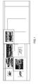
- Indeed, many people need to have images in their range of vision to create, and they mostly split their screen in two parts, or, for the luckiest, use two screens: one with the creation software and the other with the reference(s). As represented on
figure 1 , the desktop can be cluttered of images, and that is not convenient. - But this is not the only need the user can have about images. They can also be used as supports in 2D or 3D software to draw on it, as illustrated on
figure 2 , like using transfer paper. They can also be snapped on a 3D object to texture it, or used as input to create a logo... Images in creation context are as important as references. - Their insertion in the software is often managed by a file chooser, as illustrated on
figure 3 , or by drag and drop from a file explorer. - For example, the present invention can be implemented in the software solution provided by Dassault Systèmes under the trademark CATIA Ideas Sketch.
- Some drawbacks appear in the solutions described above.
- First, concerning the references, splitting a desktop or having several screens raised some problems such as how will the user read his emails if he needs, without acquiring another screen.
- Furthermore, it is very tiring for the eyes and the brain to always go from one side to another.
- Moreover, that is impossible on the "one process" devices such as tablets or smartphones.
- Furthermore, it is very hard work to organize the space.
- An aim of the invention is to find a more productive solution to handle such an important functionality as are reference images, and particularly for creative designers when they are sketching an industrial product, prior to modeling design.
- For images on context, the solution of drag and drop from a file explorer is not usable with "one process" devices and the file chooser solution makes hard the positioning of the file in a 3D software.
- For images on context, the solution of drag and drop from a file explorer is not usable using "one process" devices and the file chooser solution makes hard the positioning of the file in a 3D software for instance. The problem is also for importing several images.
- Thus, an aim of the invention is to think about people who are willing to use these two functionalities for images in the same time: this is not possible currently to switch easily from one to another, above all in a mobile device or in a one screen desktop.
- An aim of the invention is to provide a computer-implemented method and a system to overcome the above mentioned problems.
- It is proposed, according to one aspect of the invention, a computer-implemented method for designing a three-dimensional modeled object comprising the steps of:
- providing a three-dimensional designing scene in a display screen; and
- providing a graphical tool in a first area with a reduced size in the display area of the screen comprising at least one image, the graphical tool being permanently superimposed over the scene.
- Such a method allows to the user to easily watch images he wants to see, while he makes creation, like creative designers for sketching.
- The modeled object is related to a physical product to be manufactured in the real world subsequent to the completion of its virtual design with a CAD solution. This physical product may be an industrial product such as a mechanical product, for instance a mechanical part but not limited to. A CAD solution allows the design of products in various and unlimited industrial fields : aerospace, architecture, construction, consumer goods, high-tech devices, industrial equipment, transportation, marine, offshore or transportation.
- According to an embodiment, said reduced size of the first area represents less than a quarter of the display area of the screen.
- Thus, the most area of the screen can be used for the design.
- According to an embodiment, said reduced size of the first area represents a sixth of the display area of the screen.
- This is an embodiment particularly practical, because the graphical tool doesn't interfere with the use of the scene.
- According to an embodiment, images are arranged in a stack.
- A stack thus allows a compact arrangement that minimize the space occupied by the images and thus addresses drawbacks related to limited available screen surface, for instance with small screen devices such as a smartphone or a tablet.
- Alternatively, the graphical tool comprises a number of images inferior or equal to a threshold, images are partially superimposed such that there is no loss of more than 20% of each image, and for example in a messy arrangement.
- Thus, several images can be simultaneously displayed in the graphical tool.
- According to an embodiment, the graphical tool is extended in a second area being an horizontal banner in the display area, comprising the first area.
- Thus several images can be displayed separately in the horizontal banner.
- Alternatively, the graphical tool is extended in a third area being a vertical banner in the display area, comprising the first area.
- Thus several images can be displayed separately in the vertical banner.
- For example, images are scrolled in the banner.
- This is particularly interesting and easy to see completely several images simultaneously.
- An image can be scaled, rotated, or translated in the graphical tool.
- Furthermore, an image can be added or deleted in the graphical tool.
- Thus the graphical tool is easily configurable.
- According to an embodiment, an image of the graphical tool is imported in the scene, or an image of the scene is exported in the graphical tool.
- An importation in the scene of an image of the graphical tool being effected with a drag and drop of the image, a drop can't be taken into account when made inside a wide security area comprising the current area of the graphical tool.
- During the drag in the scene, outside the wide security area, a representation of the imported image can be represented in partial transparency at the current position of the drag.
- At the end of the drag, at the drop position, the image can be created in the scene at the drop position.
- It is also proposed, according to another aspect of the invention, a computer-readable medium having computer-executable instructions to perform the method for designing a three-dimensional modeled object as described above.
- It is also proposed, according to another aspect of the invention, a computer program product, stored on a computer readable medium, for displaying a three-dimensional modeled assembly in a scene, comprising code means for causing the system to take the steps of the method as described above.
- It is also proposed, according to another aspect of the invention, an apparatus for designing a three-dimensional modeled object comprising means for implementing the steps of the method as described above.
- The invention will be better understood with the study of some embodiments described by way of non-limiting examples and illustrated by the accompanying drawings wherein :
-
figure 1 to 3 illustrate a computer-implemented method for designing a three-dimensional modeled object, according to the state of the art; -
figures 4 to 16 illustrate a computer-implemented method for designing a three-dimensional modeled object, according to an aspect of the invention; and -
figure 17 illustrates a computer network or similar digital processing environment in which the present invention may be implemented; and -
figure 18 illustrates a diagram of the internal structure of a computer. - Following figures explain more in details the functioning of the present invention.
- In the present description, a three-dimensional model object is an object represented in 3D, i.e. with a representation, based on data, for displaying an object in any perspective in a 3D scene.
- A 3D modeled object can be, for example, a physical product, an industrial product, or a mechanical object (to be produced or manufactured).
-
Figure 4 represents a computer-implemented method for designing a three-dimensional modeled object, according to an aspect of the invention. - On the
screen 40, is provided a designingscene 41, and agraphical tool 42, or, in other words an image widget, in afirst area 43 with a reduced size in thedisplay area 44 of thescreen 40 comprising at least one image, in the present case threeimages graphical tool 42 being permanently superimposed over thescene 41. Of course, it is also possible to have no image in thegraphical tool 42, and thus only the button to import an image would be present in thegraphical tool 42. - The reduced size of the
first area 43 represents less than a quarter of thedisplay area 44 of thescreen 40, and preferably a sixth of thedisplay area 44 of thescreen 40. Thus, the most area of thedisplay area 44 of thescreen 40 can be used for the design. - As illustrated on
figure 4 , a tool embedded in the3D sketching space 44 that deals with both references and supportimages - The user is able to import some
images images graphical tool 42, they are positioned so that the user can see all the images at the same time. But if there are more than three images, they are placed in a stack where the user can navigate to find the current reference he wants to see. - This is the default behavior, but it is also possible to see all references: this
graphical tool 42 is able to turn into a banner showing all images of the stack either horizontally or vertically. - The
graphical tool 42 comprises a number of images inferior or equal to a threshold, in the present example 3,images - The first need for both functionalities is importing images. User has two ways to do that: clicking on a "plus"
button 48 which opens a file chooser wherein the user can choose the image(s) he wants to import, or dragging and dropping an image (from web browser, file explorer...) around the "plus" button, as illustrated onfigure 5 . - To represent an imported image in the
graphical tool 42, it is not created at its original size (in case of a big image). This is defined a "maximal image size" (represented by thegrey area 49 onfigure 5 ) computed also from a percentage of the screen. The image is scaled to fit this max size, keeping its ratio. - Whatever the solution used to import an image, the three first added images are positioned as illustrated on
figures 6a, 6b and 6c , in a messy arrangement. The threshold can be equal to three images, so the messy arrangement is done until three images in thegraphical tool 42. - If the user suppresses an image, in this
case image 46, for example with a long hold in any image which launches the suppression mode, as illustrated onfigures 9a and 9b , and adds anew one 50, it takes the first free area, as illustrated onfigures 7a and 7b . - Anyway, the last image is always on the top of the stack.
- As illustrated, the messy stack, has an optimal positioning that provides the user a good vision of each image without taking too much space in the creation viewer.
- The rotation of the images is important for vision and scene design, giving the "messy" look of a desktop and allowing to see each of the stack's image at the same time.
- If a fourth image is imported, the messy stack becomes a classical stack, because of the threshold equal to three images in the present example, as illustrated on
figures 8a and 8b . - It is possible to navigate into this stack by clicking on the top, or dragging the first image, by staying in the wide security area as illustrated on
figure 8c . This way, the user can either tap to change the current image, or do a little drag, like a browse in a book. Obviously, it works either with the finger, the mouse or the pen. Thus, it is possible to scroll the images as images in a circular queue or circular FIFO, during a change of the current image, the first image of the stack becomes the last image of the stack and is replaced by the second image of the stack. - Examples are given above and below with single touch gestures, but it also works with multi-touch interaction. For example a "drag" can be a drag with several fingers.
- In both representations (messy and stack), it is possible to suppress one or several images. A long hold in any image launches the suppression mode, as illustrated on
figures 9a and 9b , wherein a long hold is made onimage 50 which is thus put in front of others images of thegraphical tool 42. - The user only has to click on a cross to delete the corresponding image. He can also navigate in the stack as previously to choose the image he wants to delete.
- If the user deletes so many images that their number reaches the threshold, in this case three, the stack becomes again a messy stack, as illustrated on
figure 10 . - An interaction (drag, click, tap...) anywhere else on the screen quits the suppression mode.
- But messy and classical stack view modes are not the only available representations. It is possible to switch to new ones doing a horizontal or vertical drag on any of previous views. The images are then put in a banner.
- On
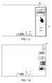
figures 11a and 11b is represented an example wherein thegraphical tool 42 is extended in asecond area 52 being an horizontal banner. - On
figures 11c and 11d is represented an example wherein thegraphical tool 42 is extended in athird area 53 being a vertical banner. - The
second area 52 and thethird area 53 comprises thefirst area 43. - As illustrated on
figure 12 , If there are too many images to fit in the second 52 orthird area 53, the area becomes scrollable so that the user can navigate through as many references as he needs. He just has to scroll to access the invisible objects. - To switch back to previous mode (messy or stack), the user has to do a drag that stops in the
first area 43, as illustrated onfigures 13a and13b , in an example of an horizontal banner. - In all the representations, it is also possible to modify each image (scale, rotate, translate). An example of rotation and scaling is illustrated on
figure 14 . - To put an image in the 3D scene, the user only has to drag and drop an image of the
graphical tool 42 in the screen, going out of awide security area 54. The wide security area comprises thecurrent area graphical tool 42. The user can switch in and out the wide security area, but to be valid, the drop has to be outside the wide security area. The image is created at the drop position. Thus, the wide security area can be identical to the current size of the graphical tool, or comprise the current size of thegraphical tool 42. - As represented on
figures 15a and 15b , during the manipulation, a "ghost" of the image, or in other words a representation of the imported image appears in partial transparency at the current position of the pointing element (finger, mouse, pen, ...) during the drag. The image is created at the drop position. -
Figure 16 represents an example of diagram representing a computer-implemented method according to an aspect of the invention, as previously disclosed. - A
test 60 allows to know if the user releases or not the pointing element (finger, pen, mouse, ...). - If
test 60 is negative (pointing element not released), atest 61 allows to know if the pointing element is outside the wide security area. - If
test 61 is positive (pointing element outside the wide security area, in the designing scene 41), a ghost is created 62, i.e. a representation of the imported image appears in partial transparency at the current position of the pointing element (finger, mouse, pen, ...) during the drag. - If
test 61 is negative, a ghost is deleted, or, not created 63. - If
test 60 is positive (pointing element released), atest 64 allows to know if the pointing element is outside the wide security area. - If
test 64 is positive (pointing element outside the wide security area, in the designing scene 41), atest 65 allows to know if the pointing element describes an horizontal or vertical trajectory. - If
test 65 is negative, an image is create 66 at drop position, corresponding to the ghost image dragged. - If
test 65 is positive, atest 67 allows to know if thegraphical tool 42 is displayed in a default view mode, i.e. displayed in thefirst area 43. - If
test 67 is positive (graphical tool 42 displayed in default view mode), thengraphical tool 42 is displayed in the corresponding (horizontal or vertical) banner view mode 68 (respectively displayed in thesecond area 49 or third area 50). - If
test 67 is negative (graphical tool 42 displayed in banner view mode), the drop is outside. Atest 69 is effected to test if the origin of the trajectory is in thefirst area 43. If the origin of the trajectory is in thefirst area 43 the banner mode is switched 70 between horizontal and vertical. If not the image is created 66 in the 3D scene. - If
test 64 is negative (pointing element inside the wide security area), atest 71 allows to know if thegraphical tool 42 is displayed in a default view mode, i.e. displayed in thefirst area 43. - If
test 71 is positive, then the order of images of thegraphical tool 42 is modified 72, or, in other words, the order is switched. - If
test 71 is negative, atest 73 allows to know if the pointing element is inside the initial area, or in other words inside thefirst area 43. - If
test 73 is negative, ascroll 74 in horizontal or vertical banner is done. - If
test 73 is positive, the method returns 75 to default view mode, i.e. the graphical tool in thefirst area 43. -
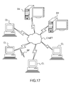
Figure 17 illustrates a computer network or similar digital processing environment in which the present invention may be implemented. - Client computer(s)/devices CL and server computer(s) SV provide processing, storage, and input/output devices executing application programs and the like. Client computer(s)/devices CL can also be linked through communications network CNET to other computing devices, including other client devices/processes CL and server computer(s) SV.
Communications network 70 can be part of a remote access network, a global network (e.g., the Internet), a worldwide collection of computers, Local area or Wide area networks, and gateways that currently use respective protocols (TCP/IP, Bluetooth, etc.) to communicate with one another. Other electronic device/computer network architectures are suitable. -
Figure 18 is a diagram of the internal structure of a computer (e.g., client processor/device CL or server computers SV) in the computer system offigure 17 . Each computer CL, SV contains system bus SB, where a bus is a set of hardware lines used for data transfer among the components of a computer or processing system. Bus SB is essentially a shared conduit that connects different elements of a computer system (e.g., processor, disk storage, memory, input/output ports, network ports, etc...) that enables the transfer of information between the elements. - Attached to system bus SB is I/O device interface DI for connecting various input and output devices (e.g., keyboard, mouse, displays, printers, speakers, etc.) to the computer CL, SV. Network interface NI allows the computer to connect to various other devices attached to a network (e.g., network CNET of
figure 17 ). - Memory MEM provides volatile storage for computer software instructions SI and data CPP used to implement an embodiment of the present invention (e.g., a first path builder PB, means CM for computing a second path, an updater UD implementing the method discussed in
Figs 1 to 17 , and supporting code detailed above). - Disk storage DS provides non-volatile storage for computer software instructions SI and data DAT used to implement an embodiment of the present invention. Central processor unit CPU is also attached to system bus SB and provides for the execution of computer instructions.
- In one embodiment, the processor routines SI and data DAT are a computer program product (generally referenced CPP), including a computer readable medium (e.g., a removable storage medium such as one or more DVD-ROM's, CD-ROM's, diskettes, tapes, etc...) that provides at least a portion of the software instructions for the invention system. Computer program product CPP can be installed by any suitable software installation procedure, as is well known in the art.
- In another embodiment, at least a portion of the software instructions may also be downloaded over a cable, communication and/or wireless connection. In other embodiments, the invention programs are a computer program propagated signal product SP embodied on a propagated signal on a propagation medium (e.g., a radio wave, an infrared wave, a laser wave, a sound wave, or an electrical wave propagated over a global network such as the Internet, or other network(s)). Such carrier medium or signals provide at least a portion of the software instructions for the present invention routines/program CPP.
- In alternate embodiments, the propagated signal is an analog carrier wave or digital signal carried on the propagated medium. For example, the propagated signal may be a digitized signal propagated over a global network (e.g., the Internet), a telecommunications network, or other network.
- In one embodiment, the propagated signal is a signal that is transmitted over the propagation medium over a period of time, such as the instructions for a software application sent in packets over a network over a period of milliseconds, seconds, minutes, or longer.
- In another embodiment, the computer readable medium of computer program product CPP is a propagation medium that the computer system CL may receive and read, such as by receiving the propagation medium and identifying a propagated signal embodied in the propagation medium, as described above for computer program propagated signal product.
- Generally speaking, the term "carrier medium" or transient carrier encompasses the foregoing transient signals, propagated signals, propagated medium, storage medium and the like.
- While this invention has been particularly shown and described with references to example embodiments thereof, it will be understood by those skilled in the art that various changes in form and details may be made therein without departing from the scope of the invention encompassed by the appended claims.
Claims (18)
- A computer-implemented method for designing a three-dimensional modeled object comprising the steps of:- providing a three-dimensional designing scene (41) in a display screen (40); and- providing a graphical tool (42) in a first area (43) with a reduced size in the display area (44) of the screen (40) comprising at least one image (45, 46, 47), the graphical tool (42) being permanently superimposed over the scene (41).
- Computer-implemented method of claim 1, wherein said reduced size of the first area (43) represents less than a quarter of the display area (44) of the screen (40).
- Computer-implemented method of claim 2, wherein said reduced size of the first area (43) represents a sixth of the display area (44) of the screen (40).
- Computer-implemented method of claim 1 to 3, wherein images (51, 50, 47, 45) are arranged in a stack.
- Computer-implemented method of claim 1 to 3, wherein the graphical tool (42) comprises a number of images inferior or equal to a threshold, images are partially superimposed such that there is no loss of more than 20% of each image.
- Computer-implemented method of claim 5, wherein images are messy arranged.
- Computer-implemented method of claim 1 to 6, wherein the graphical tool is extended in a second area (52) being an horizontal banner in the display area (44), comprising the first area (43).
- Computer-implemented method of claim 1 to 6, wherein the graphical tool is extended in a third area (53) being a vertical banner in the display area (44), comprising the first area (43).
- Computer-implemented method of claim 7 or 8, wherein images are scrolled in the banner.
- Computer-implemented method of claim 1 to 9, wherein an image is scaled, rotated, or translated in the graphical tool (42).
- Computer-implemented method of claim 1 to 10, wherein an image is added or deleted in the graphical tool (42).
- Computer-implemented method of claim 1 to 11, wherein an image of the graphical tool (42) is imported in the scene (41), or an image of the scene (41) is exported in the graphical tool (42).
- Computer-implemented method of claim 12, wherein, an importation in the scene (41) of an image of the graphical tool (42) being effected with a drag and drop of the image, a drop is not taken into account when made inside a wide security area comprising the current area (43, 52, 53) of the graphical tool (42).
- Computer-implemented method of claim 13, wherein, during the drag in the scene (41), outside the wide security area, a representation of the imported image is represented in partial transparency at the current position of the drag.
- Computer-implemented method of claim 14, wherein, at the end of the drag, at the drop position, the image is created in the scene (41) at the drop position.
- A computer-readable medium having computer-executable instructions to cause the computer system to perform the method for designing a three-dimensional modeled object of anyone of claims 1 to 15.
- A computer program product, stored on a computer readable medium, for designing a three-dimensional modeled object, comprising code means for causing the system to take the steps of the method of anyone of claims 1 to 15.
- An apparatus for designing a three-dimensional modeled object comprising means for implementing the steps of the method for designing a three-dimensional modeled object of anyone of claims 1 to 15.
Priority Applications (2)
| Application Number | Priority Date | Filing Date | Title |
|---|---|---|---|
| EP13306823.9A EP2887195B1 (en) | 2013-12-20 | 2013-12-20 | A computer-implemented method for designing a three-dimensional modeled object |
| US14/569,509 US9472024B2 (en) | 2013-12-20 | 2014-12-12 | Computer-implemented method for designing a three-dimensional modeled object |
Applications Claiming Priority (1)
| Application Number | Priority Date | Filing Date | Title |
|---|---|---|---|
| EP13306823.9A EP2887195B1 (en) | 2013-12-20 | 2013-12-20 | A computer-implemented method for designing a three-dimensional modeled object |
Publications (2)
| Publication Number | Publication Date |
|---|---|
| EP2887195A1 true EP2887195A1 (en) | 2015-06-24 |
| EP2887195B1 EP2887195B1 (en) | 2020-01-22 |
Family
ID=50002434
Family Applications (1)
| Application Number | Title | Priority Date | Filing Date |
|---|---|---|---|
| EP13306823.9A Active EP2887195B1 (en) | 2013-12-20 | 2013-12-20 | A computer-implemented method for designing a three-dimensional modeled object |
Country Status (2)
| Country | Link |
|---|---|
| US (1) | US9472024B2 (en) |
| EP (1) | EP2887195B1 (en) |
Families Citing this family (2)
| Publication number | Priority date | Publication date | Assignee | Title |
|---|---|---|---|---|
| US10665266B2 (en) * | 2018-03-23 | 2020-05-26 | Gfycat, Inc. | Integrating a prerecorded video file into a video |
| KR102228099B1 (en) * | 2019-08-19 | 2021-03-17 | (주)클로버추얼패션 | Method and apparatus of providing guide for combining pattern pieces of apparel |
Citations (6)
| Publication number | Priority date | Publication date | Assignee | Title |
|---|---|---|---|---|
| US20100083111A1 (en) * | 2008-10-01 | 2010-04-01 | Microsoft Corporation | Manipulation of objects on multi-touch user interface |
| US20100153844A1 (en) * | 2008-12-15 | 2010-06-17 | Verizon Data Services Llc | Three dimensional icon stacks |
| US20110246875A1 (en) * | 2010-04-02 | 2011-10-06 | Symantec Corporation | Digital whiteboard implementation |
| US20110292438A1 (en) * | 2010-05-26 | 2011-12-01 | Pfu Limited | Image reading apparatus, information processing apparatus, image processing method, and computer program product |
| EP2490113A1 (en) * | 2011-02-15 | 2012-08-22 | Lg Electronics Inc. | Display device and method of controlling operation thereof |
| US20130069860A1 (en) * | 2009-05-21 | 2013-03-21 | Perceptive Pixel Inc. | Organizational Tools on a Multi-touch Display Device |
Family Cites Families (1)
| Publication number | Priority date | Publication date | Assignee | Title |
|---|---|---|---|---|
| WO2007033354A2 (en) * | 2005-09-13 | 2007-03-22 | Spacetime3D, Inc. | System and method for providing three-dimensional graphical user interface |
-
2013
- 2013-12-20 EP EP13306823.9A patent/EP2887195B1/en active Active
-
2014
- 2014-12-12 US US14/569,509 patent/US9472024B2/en active Active
Patent Citations (6)
| Publication number | Priority date | Publication date | Assignee | Title |
|---|---|---|---|---|
| US20100083111A1 (en) * | 2008-10-01 | 2010-04-01 | Microsoft Corporation | Manipulation of objects on multi-touch user interface |
| US20100153844A1 (en) * | 2008-12-15 | 2010-06-17 | Verizon Data Services Llc | Three dimensional icon stacks |
| US20130069860A1 (en) * | 2009-05-21 | 2013-03-21 | Perceptive Pixel Inc. | Organizational Tools on a Multi-touch Display Device |
| US20110246875A1 (en) * | 2010-04-02 | 2011-10-06 | Symantec Corporation | Digital whiteboard implementation |
| US20110292438A1 (en) * | 2010-05-26 | 2011-12-01 | Pfu Limited | Image reading apparatus, information processing apparatus, image processing method, and computer program product |
| EP2490113A1 (en) * | 2011-02-15 | 2012-08-22 | Lg Electronics Inc. | Display device and method of controlling operation thereof |
Also Published As
| Publication number | Publication date |
|---|---|
| US9472024B2 (en) | 2016-10-18 |
| US20150178991A1 (en) | 2015-06-25 |
| EP2887195B1 (en) | 2020-01-22 |
Similar Documents
| Publication | Publication Date | Title |
|---|---|---|
| Bowman et al. | New directions in 3d user interfaces | |
| Fu et al. | Multi-touch techniques for exploring large-scale 3D astrophysical simulations | |
| US20120092340A1 (en) | Systems, methods, and computer-readable media for manipulating graphical objects | |
| EP2814000B1 (en) | Image processing apparatus, image processing method, and program | |
| US10839572B2 (en) | Contextual virtual reality interaction | |
| CN105493023A (en) | Manipulation of content on a surface | |
| Fiorentino et al. | Design review of CAD assemblies using bimanual natural interface | |
| KR20060052717A (en) | Virtual desktop-meta-organization & control system | |
| US20220129079A1 (en) | Method and system for viewing virtual elements | |
| JP5992934B2 (en) | 3D viewing method | |
| Newbury et al. | Embodied gesture interaction for immersive maps | |
| EP2800020B1 (en) | A computer-implemented method for manipulating three-dimensional modeled objects of an assembly in a three-dimensional scene. | |
| US9472024B2 (en) | Computer-implemented method for designing a three-dimensional modeled object | |
| EP2889738B1 (en) | Computer-implemented method for designing a three-dimensional modeled object | |
| CN103237086A (en) | Information transmission system and information transmission method | |
| US20160216858A1 (en) | Method and program product for an interactive e-book | |
| Daiber et al. | Towards a framework for whole body interaction with geospatial data | |
| Huang et al. | Investigating one-handed and two-handed inter-device interaction | |
| CN102622178A (en) | Touch screen electronic equipment-based method for warping plane image | |
| KR101420818B1 (en) | Method of embodying three-dimensional object animation, apparatus performing the same and storage media storing the same | |
| US11393171B2 (en) | Mobile device based VR content control | |
| US9633476B1 (en) | Method and apparatus for using augmented reality for business graphics | |
| Amant | Natural interaction with visualization systems | |
| Boonyasaknanon et al. | Geologic Modelling Using Augmented Reality | |
| Opiyo | Interface modes for interactive visualization of airborne product virtual models |
Legal Events
| Date | Code | Title | Description |
|---|---|---|---|
| PUAI | Public reference made under article 153(3) epc to a published international application that has entered the european phase |
Free format text: ORIGINAL CODE: 0009012 |
|
| 17P | Request for examination filed |
Effective date: 20131220 |
|
| AK | Designated contracting states |
Kind code of ref document: A1 Designated state(s): AL AT BE BG CH CY CZ DE DK EE ES FI FR GB GR HR HU IE IS IT LI LT LU LV MC MK MT NL NO PL PT RO RS SE SI SK SM TR |
|
| AX | Request for extension of the european patent |
Extension state: BA ME |
|
| R17P | Request for examination filed (corrected) |
Effective date: 20151123 |
|
| RBV | Designated contracting states (corrected) |
Designated state(s): AL AT BE BG CH CY CZ DE DK EE ES FI FR GB GR HR HU IE IS IT LI LT LU LV MC MK MT NL NO PL PT RO RS SE SI SK SM TR |
|
| STAA | Information on the status of an ep patent application or granted ep patent |
Free format text: STATUS: EXAMINATION IS IN PROGRESS |
|
| 17Q | First examination report despatched |
Effective date: 20180914 |
|
| GRAP | Despatch of communication of intention to grant a patent |
Free format text: ORIGINAL CODE: EPIDOSNIGR1 |
|
| STAA | Information on the status of an ep patent application or granted ep patent |
Free format text: STATUS: GRANT OF PATENT IS INTENDED |
|
| RIC1 | Information provided on ipc code assigned before grant |
Ipc: G06F 3/0484 20130101ALI20190708BHEP Ipc: G06T 15/08 20110101ALI20190708BHEP Ipc: G06F 3/0483 20130101ALI20190708BHEP Ipc: G06F 3/0482 20130101AFI20190708BHEP Ipc: G06F 3/0486 20130101ALI20190708BHEP Ipc: G06T 19/00 20110101ALI20190708BHEP |
|
| INTG | Intention to grant announced |
Effective date: 20190802 |
|
| GRAS | Grant fee paid |
Free format text: ORIGINAL CODE: EPIDOSNIGR3 |
|
| GRAA | (expected) grant |
Free format text: ORIGINAL CODE: 0009210 |
|
| STAA | Information on the status of an ep patent application or granted ep patent |
Free format text: STATUS: THE PATENT HAS BEEN GRANTED |
|
| AK | Designated contracting states |
Kind code of ref document: B1 Designated state(s): AL AT BE BG CH CY CZ DE DK EE ES FI FR GB GR HR HU IE IS IT LI LT LU LV MC MK MT NL NO PL PT RO RS SE SI SK SM TR |
|
| REG | Reference to a national code |
Ref country code: GB Ref legal event code: FG4D |
|
| REG | Reference to a national code |
Ref country code: CH Ref legal event code: EP |
|
| REG | Reference to a national code |
Ref country code: AT Ref legal event code: REF Ref document number: 1227340 Country of ref document: AT Kind code of ref document: T Effective date: 20200215 |
|
| REG | Reference to a national code |
Ref country code: IE Ref legal event code: FG4D |
|
| REG | Reference to a national code |
Ref country code: DE Ref legal event code: R096 Ref document number: 602013065262 Country of ref document: DE |
|
| REG | Reference to a national code |
Ref country code: SE Ref legal event code: TRGR |
|
| REG | Reference to a national code |
Ref country code: NL Ref legal event code: MP Effective date: 20200122 |
|
| REG | Reference to a national code |
Ref country code: LT Ref legal event code: MG4D |
|
| PG25 | Lapsed in a contracting state [announced via postgrant information from national office to epo] |
Ref country code: FI Free format text: LAPSE BECAUSE OF FAILURE TO SUBMIT A TRANSLATION OF THE DESCRIPTION OR TO PAY THE FEE WITHIN THE PRESCRIBED TIME-LIMIT Effective date: 20200122 Ref country code: NO Free format text: LAPSE BECAUSE OF FAILURE TO SUBMIT A TRANSLATION OF THE DESCRIPTION OR TO PAY THE FEE WITHIN THE PRESCRIBED TIME-LIMIT Effective date: 20200422 Ref country code: PT Free format text: LAPSE BECAUSE OF FAILURE TO SUBMIT A TRANSLATION OF THE DESCRIPTION OR TO PAY THE FEE WITHIN THE PRESCRIBED TIME-LIMIT Effective date: 20200614 Ref country code: RS Free format text: LAPSE BECAUSE OF FAILURE TO SUBMIT A TRANSLATION OF THE DESCRIPTION OR TO PAY THE FEE WITHIN THE PRESCRIBED TIME-LIMIT Effective date: 20200122 Ref country code: NL Free format text: LAPSE BECAUSE OF FAILURE TO SUBMIT A TRANSLATION OF THE DESCRIPTION OR TO PAY THE FEE WITHIN THE PRESCRIBED TIME-LIMIT Effective date: 20200122 |
|
| PG25 | Lapsed in a contracting state [announced via postgrant information from national office to epo] |
Ref country code: GR Free format text: LAPSE BECAUSE OF FAILURE TO SUBMIT A TRANSLATION OF THE DESCRIPTION OR TO PAY THE FEE WITHIN THE PRESCRIBED TIME-LIMIT Effective date: 20200423 Ref country code: IS Free format text: LAPSE BECAUSE OF FAILURE TO SUBMIT A TRANSLATION OF THE DESCRIPTION OR TO PAY THE FEE WITHIN THE PRESCRIBED TIME-LIMIT Effective date: 20200522 Ref country code: BG Free format text: LAPSE BECAUSE OF FAILURE TO SUBMIT A TRANSLATION OF THE DESCRIPTION OR TO PAY THE FEE WITHIN THE PRESCRIBED TIME-LIMIT Effective date: 20200422 Ref country code: HR Free format text: LAPSE BECAUSE OF FAILURE TO SUBMIT A TRANSLATION OF THE DESCRIPTION OR TO PAY THE FEE WITHIN THE PRESCRIBED TIME-LIMIT Effective date: 20200122 Ref country code: LV Free format text: LAPSE BECAUSE OF FAILURE TO SUBMIT A TRANSLATION OF THE DESCRIPTION OR TO PAY THE FEE WITHIN THE PRESCRIBED TIME-LIMIT Effective date: 20200122 |
|
| REG | Reference to a national code |
Ref country code: DE Ref legal event code: R097 Ref document number: 602013065262 Country of ref document: DE |
|
| PG25 | Lapsed in a contracting state [announced via postgrant information from national office to epo] |
Ref country code: LT Free format text: LAPSE BECAUSE OF FAILURE TO SUBMIT A TRANSLATION OF THE DESCRIPTION OR TO PAY THE FEE WITHIN THE PRESCRIBED TIME-LIMIT Effective date: 20200122 Ref country code: ES Free format text: LAPSE BECAUSE OF FAILURE TO SUBMIT A TRANSLATION OF THE DESCRIPTION OR TO PAY THE FEE WITHIN THE PRESCRIBED TIME-LIMIT Effective date: 20200122 Ref country code: EE Free format text: LAPSE BECAUSE OF FAILURE TO SUBMIT A TRANSLATION OF THE DESCRIPTION OR TO PAY THE FEE WITHIN THE PRESCRIBED TIME-LIMIT Effective date: 20200122 Ref country code: SM Free format text: LAPSE BECAUSE OF FAILURE TO SUBMIT A TRANSLATION OF THE DESCRIPTION OR TO PAY THE FEE WITHIN THE PRESCRIBED TIME-LIMIT Effective date: 20200122 Ref country code: DK Free format text: LAPSE BECAUSE OF FAILURE TO SUBMIT A TRANSLATION OF THE DESCRIPTION OR TO PAY THE FEE WITHIN THE PRESCRIBED TIME-LIMIT Effective date: 20200122 Ref country code: CZ Free format text: LAPSE BECAUSE OF FAILURE TO SUBMIT A TRANSLATION OF THE DESCRIPTION OR TO PAY THE FEE WITHIN THE PRESCRIBED TIME-LIMIT Effective date: 20200122 Ref country code: RO Free format text: LAPSE BECAUSE OF FAILURE TO SUBMIT A TRANSLATION OF THE DESCRIPTION OR TO PAY THE FEE WITHIN THE PRESCRIBED TIME-LIMIT Effective date: 20200122 Ref country code: SK Free format text: LAPSE BECAUSE OF FAILURE TO SUBMIT A TRANSLATION OF THE DESCRIPTION OR TO PAY THE FEE WITHIN THE PRESCRIBED TIME-LIMIT Effective date: 20200122 |
|
| REG | Reference to a national code |
Ref country code: AT Ref legal event code: MK05 Ref document number: 1227340 Country of ref document: AT Kind code of ref document: T Effective date: 20200122 |
|
| PLBE | No opposition filed within time limit |
Free format text: ORIGINAL CODE: 0009261 |
|
| STAA | Information on the status of an ep patent application or granted ep patent |
Free format text: STATUS: NO OPPOSITION FILED WITHIN TIME LIMIT |
|
| 26N | No opposition filed |
Effective date: 20201023 |
|
| PG25 | Lapsed in a contracting state [announced via postgrant information from national office to epo] |
Ref country code: AT Free format text: LAPSE BECAUSE OF FAILURE TO SUBMIT A TRANSLATION OF THE DESCRIPTION OR TO PAY THE FEE WITHIN THE PRESCRIBED TIME-LIMIT Effective date: 20200122 |
|
| PG25 | Lapsed in a contracting state [announced via postgrant information from national office to epo] |
Ref country code: SI Free format text: LAPSE BECAUSE OF FAILURE TO SUBMIT A TRANSLATION OF THE DESCRIPTION OR TO PAY THE FEE WITHIN THE PRESCRIBED TIME-LIMIT Effective date: 20200122 Ref country code: PL Free format text: LAPSE BECAUSE OF FAILURE TO SUBMIT A TRANSLATION OF THE DESCRIPTION OR TO PAY THE FEE WITHIN THE PRESCRIBED TIME-LIMIT Effective date: 20200122 |
|
| REG | Reference to a national code |
Ref country code: CH Ref legal event code: PL |
|
| PG25 | Lapsed in a contracting state [announced via postgrant information from national office to epo] |
Ref country code: MC Free format text: LAPSE BECAUSE OF FAILURE TO SUBMIT A TRANSLATION OF THE DESCRIPTION OR TO PAY THE FEE WITHIN THE PRESCRIBED TIME-LIMIT Effective date: 20200122 |
|
| REG | Reference to a national code |
Ref country code: BE Ref legal event code: MM Effective date: 20201231 |
|
| PG25 | Lapsed in a contracting state [announced via postgrant information from national office to epo] |
Ref country code: IE Free format text: LAPSE BECAUSE OF NON-PAYMENT OF DUE FEES Effective date: 20201220 Ref country code: LU Free format text: LAPSE BECAUSE OF NON-PAYMENT OF DUE FEES Effective date: 20201220 |
|
| PG25 | Lapsed in a contracting state [announced via postgrant information from national office to epo] |
Ref country code: LI Free format text: LAPSE BECAUSE OF NON-PAYMENT OF DUE FEES Effective date: 20201231 Ref country code: CH Free format text: LAPSE BECAUSE OF NON-PAYMENT OF DUE FEES Effective date: 20201231 |
|
| PG25 | Lapsed in a contracting state [announced via postgrant information from national office to epo] |
Ref country code: TR Free format text: LAPSE BECAUSE OF FAILURE TO SUBMIT A TRANSLATION OF THE DESCRIPTION OR TO PAY THE FEE WITHIN THE PRESCRIBED TIME-LIMIT Effective date: 20200122 Ref country code: MT Free format text: LAPSE BECAUSE OF FAILURE TO SUBMIT A TRANSLATION OF THE DESCRIPTION OR TO PAY THE FEE WITHIN THE PRESCRIBED TIME-LIMIT Effective date: 20200122 Ref country code: CY Free format text: LAPSE BECAUSE OF FAILURE TO SUBMIT A TRANSLATION OF THE DESCRIPTION OR TO PAY THE FEE WITHIN THE PRESCRIBED TIME-LIMIT Effective date: 20200122 |
|
| PG25 | Lapsed in a contracting state [announced via postgrant information from national office to epo] |
Ref country code: MK Free format text: LAPSE BECAUSE OF FAILURE TO SUBMIT A TRANSLATION OF THE DESCRIPTION OR TO PAY THE FEE WITHIN THE PRESCRIBED TIME-LIMIT Effective date: 20200122 Ref country code: AL Free format text: LAPSE BECAUSE OF FAILURE TO SUBMIT A TRANSLATION OF THE DESCRIPTION OR TO PAY THE FEE WITHIN THE PRESCRIBED TIME-LIMIT Effective date: 20200122 |
|
| PG25 | Lapsed in a contracting state [announced via postgrant information from national office to epo] |
Ref country code: BE Free format text: LAPSE BECAUSE OF NON-PAYMENT OF DUE FEES Effective date: 20201231 |
|
| P01 | Opt-out of the competence of the unified patent court (upc) registered |
Effective date: 20230529 |
|
| PGFP | Annual fee paid to national office [announced via postgrant information from national office to epo] |
Ref country code: GB Payment date: 20231116 Year of fee payment: 11 |
|
| PGFP | Annual fee paid to national office [announced via postgrant information from national office to epo] |
Ref country code: SE Payment date: 20231127 Year of fee payment: 11 Ref country code: IT Payment date: 20231128 Year of fee payment: 11 Ref country code: FR Payment date: 20231122 Year of fee payment: 11 Ref country code: DE Payment date: 20231114 Year of fee payment: 11 |