EP2887148A1 - Toner conveying device, image forming apparatus - Google Patents
Toner conveying device, image forming apparatus Download PDFInfo
- Publication number
- EP2887148A1 EP2887148A1 EP14197884.1A EP14197884A EP2887148A1 EP 2887148 A1 EP2887148 A1 EP 2887148A1 EP 14197884 A EP14197884 A EP 14197884A EP 2887148 A1 EP2887148 A1 EP 2887148A1
- Authority
- EP
- European Patent Office
- Prior art keywords
- opening
- shutter member
- shutter
- toner
- cylindrical member
- Prior art date
- Legal status (The legal status is an assumption and is not a legal conclusion. Google has not performed a legal analysis and makes no representation as to the accuracy of the status listed.)
- Withdrawn
Links
Images








Classifications
-
- G—PHYSICS
- G03—PHOTOGRAPHY; CINEMATOGRAPHY; ANALOGOUS TECHNIQUES USING WAVES OTHER THAN OPTICAL WAVES; ELECTROGRAPHY; HOLOGRAPHY
- G03G—ELECTROGRAPHY; ELECTROPHOTOGRAPHY; MAGNETOGRAPHY
- G03G15/00—Apparatus for electrographic processes using a charge pattern
- G03G15/06—Apparatus for electrographic processes using a charge pattern for developing
- G03G15/08—Apparatus for electrographic processes using a charge pattern for developing using a solid developer, e.g. powder developer
- G03G15/0822—Arrangements for preparing, mixing, supplying or dispensing developer
- G03G15/0877—Arrangements for metering and dispensing developer from a developer cartridge into the development unit
- G03G15/0881—Sealing of developer cartridges
- G03G15/0886—Sealing of developer cartridges by mechanical means, e.g. shutter, plug
-
- G—PHYSICS
- G03—PHOTOGRAPHY; CINEMATOGRAPHY; ANALOGOUS TECHNIQUES USING WAVES OTHER THAN OPTICAL WAVES; ELECTROGRAPHY; HOLOGRAPHY
- G03G—ELECTROGRAPHY; ELECTROPHOTOGRAPHY; MAGNETOGRAPHY
- G03G21/00—Arrangements not provided for by groups G03G13/00 - G03G19/00, e.g. cleaning, elimination of residual charge
- G03G21/10—Collecting or recycling waste developer
- G03G21/105—Arrangements for conveying toner waste
Definitions
- the present disclosure relates to a toner conveying device for conveying toner, and an image forming apparatus.
- an electrostatic latent image formed on an image carrier such as a photoconductor drum is visualized with developer (toner) in a developing device, and the toner image is transferred to a recording medium.
- developer toner
- toner that has not been transferred to the recording medium may remain on the surface of the photoconductor drum.
- a cleaning device removes the remaining toner (waste toner) from the surface of the photoconductor drum.
- the toner removed from the surface of the photoconductor drum is conveyed by a screw as the waste toner, and then recovered in a waste bottle.
- the photoconductor drum, cleaning blade and the like have shorter lives than the image forming apparatus.
- these parts are normally provided as a unit that can be installed in the apparatus main body in an attachable/detachable manner as a replacement part (hereinafter, the unit is referred to as "cleaning unit").
- cleaning unit an opening is formed in the cleaning unit to allow a waste toner conveyance path in the cleaning unit to communicate with the waste bottle.
- the cleaning unit is attached to and detached from the apparatus main body. As a result, when the cleaning unit is detached from the apparatus main body, it is necessary to prevent the waste toner remaining in the cleaning unit from leaking from the opening.
- a shutter member is provided to open and close the opening.
- an end of a casing of the cleaning unit on the downstream side in the conveyance path is formed in a shape of a cylinder, and the above-mentioned opening is formed in a lower part of the cylindrical portion.
- the shutter member is formed in the shape of a cup to be externally fitted with the cylindrical portion, and has an opening of a shape corresponding to the opening of the casing.
- the shutter member is configured to be rotated in the circumferential direction between a closing position and an opening position, wherein at the closing position, the opening of the casing is closed by the shutter member, and at the opening position, the opening of the casing overlaps with the opening of the shutter member, and the waste toner conveyance path in the cleaning unit is communicated with the waste bottle.
- a toner conveying device includes a cylindrical member, a shutter member, and a shutter opening/closing mechanism.
- the cylindrical member is provided at an end of a toner conveyance path in which toner is conveyed, the cylindrical member having a first opening from which the toner is discharged, the end of the toner conveyance path being on a downstream side in a toner conveyance direction.
- the shutter member is formed in a shape of a cylinder with a bottom and configured to be externally fitted with the cylindrical member and open and close the first opening.
- the shutter opening/closing mechanism is configured to cause the shutter member to pivot between an open position at which the first opening is opened and a closed position at which the first opening is closed, while moving the shutter member in a direction along an axis around which the shutter member pivots such that at the closed position, a bottom surface of the shutter member and a side edge of the cylindrical member are pressed against each other.
- An image forming apparatus includes a cleaning member, a cylindrical member, a shutter member, and a shutter opening/closing mechanism.
- the cleaning member is configured to remove toner from a surface of a photoconductor drum that carries a toner image.
- the cylindrical member is provided at a downstream-side end of a waste toner conveyance path in which waste toner removed by the cleaning member is conveyed, and has a first opening from which the waste toner is discharged, the downstream-side end being on a downstream side in a waste toner conveyance direction of the waste toner conveyance path.
- the shutter member is formed in a shape of a cylinder with a bottom and configured to be externally fitted with the cylindrical member and open and close the first opening.
- the shutter opening/closing mechanism is configured to cause the shutter member to pivot between positions of an open position at which the first opening is opened and a closed position at which the first opening is closed, while moving the shutter member in a direction along an axis around which the shutter member pivots such that at the closed position, a bottom surface of the shutter member and a side edge of the cylindrical member are pressed against each other.
- An image forming apparatus 1 shown in FIG. 1 is an example of the image forming apparatus of the present disclosure.
- a front direction Fr shown in FIG. 1 may be used for explanation.
- the image forming apparatus 1 is a multifunction peripheral having functions of a printer, a facsimile and the like.
- the image forming apparatus 1 prints an input image onto a print sheet by using a print material such as toner. It is noted that the image forming apparatus 1 is not limited to a multifunction peripheral, but may be an apparatus such as a printer, facsimile, or copier.
- the image forming apparatus 1 includes an apparatus main body 2, a sheet feed cassette 3, a sheet discharge tray 5, a sheet feed portion 11, an intermediate transfer unit 4, an image forming portion 21, a secondary transfer portion 14, and a fixing portion 15.
- the sheet feed cassette 3 is provided in a lower part of the apparatus main body 2, and configured to store a plurality of print sheets in a stacked state.
- the sheet discharge tray 5 is provided on an upper surface of the apparatus main body 2.
- the sheet feed portion 11 supplies, one by one, the print sheets set in the sheet feed cassette 3 to a conveyance path 10.
- the image forming portion 21 primary-transfers a toner image onto an intermediate transfer belt 12 that is described below.
- the secondary transfer portion 14 secondary-transfers the toner image that has been temporarily transferred on the intermediate transfer belt 12, to a print sheet.
- the fixing portion 15 fixes, to the print sheet, the toner image that has been secondary-transferred to the print sheet.
- the intermediate transfer unit 4 includes the intermediate transfer belt 12, a driving roller 12a, and a tension roller 12b.
- the intermediate transfer belt 12 is a belt having a shape of an endless loop and is made of rubber, urethane or other material.
- the intermediate transfer belt 12 is wound around the driving roller 12a and the tension roller 12b, and is run in the front direction Fr and in the opposite direction as the driving roller 12a is driven and rotated by a driving motor (not shown).
- the driving roller 12a is disposed close to the fixing portion 15 (on the right side in FIG. 1 ).
- the tension roller 12b is disposed away from the fixing portion 15 (on the left side in FIG. 1 ).
- the surface of the tension roller 12b is made of rubber, urethane or other material that increases friction force with the driving roller 12a.
- the image forming apparatus 1 of the present embodiment is a so-called tandem color image forming apparatus, and includes a plurality of image forming portions 21.
- the plurality of image forming portions 21 are aligned in the left-right direction in FIG. 1 .
- the plurality of image forming portions 21 form toner images of different colors, and in an order from the right in FIG. 1 , an image forming portion for black, an image forming portion for cyan, an image forming portion for magenta, and an image forming portion for yellow are arranged in a row.
- the image forming portions 21 form images using replenishing toner of a plurality of colors (Y, M, C, K) stored in a plurality of toner containers 20.
- Each of the image forming portions 21 includes a photoconductor drum 24, a charging portion 25, a cleaning unit 26, a developing portion 27, and a primary transfer roller 28.
- the photoconductor drum 24 carries a toner image.
- the charging portion 25 uniformly charges the surface of the photoconductor drum 24.
- the developing portion 27 develops an electrostatic latent image on the photoconductor drum 24 by using toner.
- the primary transfer roller 28 transfers the toner image from the surface of the rotating photoconductor drum 24 to a moving intermediate transfer belt 12.
- the cleaning unit 26 removes remaining waste toner from the surface of the photoconductor drum 24.
- An exposure portion 22 is provided below the image forming portion 21.
- the exposure portion 22 forms the electrostatic latent image by exposing the charged surface of the photoconductor drum 24 to scanning light.
- the toner containers 20 that are aligned below the sheet discharge tray 5 have been installed in the apparatus main body 2 each in an attachable/detachable manner.
- the surface of the photoconductor drum 24 is uniformly charged by the charging portion 25.
- the exposure portion 22 performs exposure on the photoconductor drum 24 based on image data. With this exposure, an electrostatic latent image is formed on the surface of the photoconductor drum 24.
- the developing portion 27 then visualizes the electrostatic latent image (forms a toner image) by using toner supplied from the toner containers 20.
- the toner image formed on the surface of the photoconductor drum 24 is transferred to the surface of the running intermediate transfer belt 12.
- the waste toner that has remained on the surface of the photoconductor drum 24 is removed by the cleaning unit 26.
- the print sheet supplied by the sheet feed portion 11 from the sheet feed cassette 3 is passed through the conveyance path 10 and conveyed to the secondary transfer portion 14.
- the secondary transfer portion 14 When a bias is applied to the secondary transfer portion 14, the color toner image formed on the surface of the intermediate transfer belt 12 is secondary-transferred to the print sheet.
- the print sheet is subjected to a fixing process by the fixing portion 15, and is ejected onto the sheet discharge tray 5.
- the photoconductor drum 24, charging portion 25, and cleaning unit 26 are provided as a unit.
- This unit is referred to as a drum unit 21a. The following explains a movement path of the waste toner removed from the photoconductor drum 24.
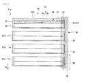
- the waste toner removed from the photoconductor drum 24 in each drum unit 21a drops to a first conveyance path 36 (see FIG. 4 ) of each cleaning unit 26, the first conveyance path 36 being described below.
- the waste toner accumulated in the first conveyance path 36 is conveyed in the downstream direction toward a first opening 37 by the rotation of a first screw member 32 provided in a casing 30 (see FIG. 3 ) of the cleaning unit 26.
- the image forming apparatus 1 includes a waste toner conveying device 50 that conveys, into a waste toner bottle 59, the waste toner that has been conveyed by the cleaning units 26.
- the waste toner conveying device 50 is configured to be connected with the cleaning units 26 that are arranged in the front-rear direction of the image forming apparatus 1.
- a second conveyance path 56 extends in the front-rear direction.
- the second conveyance path 56 includes inlets 53 for introducing the waste toner from the respective cleaning units 26.
- a second screw member 57 is disposed in the second conveyance path 56.
- the second screw member 57 has the same configuration as the first screw member 32.
- the opposite ends of the second screw member 57 in the axis direction are rotatably supported by the inner wall of the second conveyance path 56.
- the second screw member 57 is driven and rotated by a driving motor (not shown).
- a second outlet 58 is formed at a downstream-side end of the second conveyance path 56. The second outlet 58 communicates with the waste toner bottle 59.
- the image forming apparatus 1 of the present embodiment includes a shutter member 33 that, as described below, plays a role in the communication and blockage between the first conveyance path 36 in the cleaning unit 26 and the second conveyance path 56 in the waste toner conveying device 50.
- a shutter member 33 that, as described below, plays a role in the communication and blockage between the first conveyance path 36 in the cleaning unit 26 and the second conveyance path 56 in the waste toner conveying device 50. The following describes specific configuration of each portion.
- the photoconductor drum 24 is rotatably supported by a pair of supporting frames 23 provided at the opposite ends of the drum unit 21a in the axis direction.
- a drum driving gear 24b is attached to an upstream-side end (the right end in FIG. 3 ) of the photoconductor drum 24, with a supporting frame 23 therebetween.
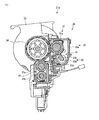
- the drum driving gear 24b meshes with a driving gear 29 that is driven and rotated by a driving motor (not shown) (see FIGS. 15A and 15B ).
- a driving motor not shown
- the charging portion 25 includes a charging roller 25a and a rubbing roller 25b.
- the charging roller 25a slidably contacts the photoconductor drum 24.
- the rubbing roller 25b polishes the surface of the charging roller 25a.
- the cleaning unit 26 includes the casing 30, a cleaning member 31, the first screw member 32, the shutter member 33, a shutter opening/closing mechanism 34, and a screw moving mechanism 35.
- the cleaning unit 26 is an example of the toner conveying device of the present disclosure. More specifically, a second cylindrical portion 30c (described below), the shutter member 33, and the shutter opening/closing mechanism 34 that are included in the casing 30 configure the toner conveying device of the present disclosure.
- the casing 30 supports the cleaning member 31 and the like.
- the casing 30 includes a casing main body 30a, a first cylindrical portion 30b, and the second cylindrical portion 30c.
- the casing main body 30a extends along the axis direction of the photoconductor drum 24, and has an opening on the photoconductor drum 24 side. As shown in FIG. 3 , the casing main body 30a is shorter than the photoconductor drum 24 in length in the axis direction, and is supported by the supporting frames 23 via connecting arms 30d at the opposite ends of the drum unit 21a.
- the first cylindrical portion 30b and the second cylindrical portion 30c are each formed in the shape of a cylinder.
- the first cylindrical portion 30b projects outward from an upstream-side end (the right end in FIG. 3 ) of the casing main body 30a.
- the second cylindrical portion 30c projects outward from a downstream-side end (the left end in FIG. 3 ) of the casing main body 30a.
- a part of an end of the second cylindrical portion 30c is cut to form the first opening 37 that is communicable with the first conveyance path 36.
- a slant guide surface 301c is formed on an end of the second cylindrical portion 30c at a position different from the position of the cut in the circumferential direction, wherein the slant guide surface 301c is a slant surface that extends slanting with respect to the circumferential direction of the second cylindrical portion 30c.
- a slant portion 66 (described below) of the shutter member 33 slidably contacts the slant guide surface 301c. Upon the contact, the slant guide surface 301c guides the shutter member 33 to pivot around the axis and move in the axis direction.
- a projection 61 is provided on an outer circumferential surface of the second cylindrical portion 30c.
- the second cylindrical portion 30c is an example of the cylindrical member.
- the first conveyance path 36 for conveying the waste toner is defined by the first cylindrical portion 30b, casing main body 30a, and second cylindrical portion 30c.
- the cleaning member 31 includes a cleaning roller 31a and a cleaning blade 31b.
- the opposite ends of the cleaning roller 31a in the axis direction are rotatably supported by the casing main body 30a. A part of the circumferential surface of the cleaning roller 31a abuts on the surface of the photoconductor drum 24 via the opening of the casing 30.
- the cleaning roller 31a is driven and rotated by a driving motor (not shown) in an opposite direction to the photoconductor drum 24, thereby removing the waste toner that has remained on the surface of the photoconductor drum 24 after transferring of a toner image to the primary transfer roller 28.
- the cleaning blade 31b is provided below the cleaning roller 31a.
- the cleaning blade 31b is made of urethane rubber or other material and is elastic.
- An upper part of the cleaning roller 31a is a free end and is elastically pressed against the surface of the photoconductor drum 24. With this configuration, the waste toner on the surface of the photoconductor drum 24 is scraped. In this way, the cleaning member 31 removes toner from the surface of the photoconductor drum 24 that carries the toner image.
- the first screw member 32 conveys the waste toner in the first conveyance path 36 formed in the casing 30.
- the first screw member 32 includes a rotary shaft 32a and a helical vane 32b.
- the rotary shaft 32a extends along the first conveyance path 36.
- the helical vane 32b is helically formed on the circumferential surface of the rotary shaft 32a.
- the first screw member 32 passes through the first cylindrical portion 30b and extends toward the upstream side.
- a driven gear 41 (see FIG. 3 ) is attached to an upstream-side end of the first screw member 32.
- the shutter member 33 has a shape of a cylinder with a bottom, and is externally fitted with the second cylindrical portion 30c (see FIGS. 11A and 11B ).
- the shutter member 33 opens and closes the first opening 37 of the second cylindrical portion 30c.
- a rectangular outlet 42 is formed in a circumferential wall 33a of the shutter member 33.
- a cylindrical downstream-side bearing 43 is formed on an inner surface 66b of a bottom wall 33b of the shutter member 33.
- the downstream-side bearing 43 rotatably supports a downstream-side end of the first screw member 32.
- the downstream-side bearing 43 projects toward the upstream side in the axis direction from the center of the inner surface of the shutter member 33, and is fitted with the rotary shaft 32a of the first screw member 32 in an insertable/removable manner.
- an upstream-side bearing 38 is formed at a part where the casing main body 30a is connected with the first cylindrical portion 30b, and the upstream-side bearing 38 rotatably supports an upstream-side end of the first screw member 32.
- the opposite ends of the first screw member 32 are pivotally supported by the upstream-side bearing 38 and the downstream-side bearing 43 of the shutter member 33.
- the circumferential wall 33a of the shutter member 33 includes a second opening 60 and a lever 63.
- the second opening 60 is formed at an upstream of the outlet 42 on the circumferential wall 33a of the shutter member 33.
- the second opening 60 extends slanting with respect to the circumferential direction of the circumferential wall 33a.
- the second opening 60 is formed in a rectangular shape of the same width that slants such that it goes away from the bottom wall 33b of the shutter member 33 as it goes toward the upstream side.
- the second opening 60 is engaged with the projection 61 of the second cylindrical portion 30c.
- the projection 61 relatively moves in the second opening 60 as the shutter member 33 rotates around the axis.
- the engagement of the second opening 60 and the projection 61 of the second cylindrical portion 30c prevents the shutter member 33 from dropping off from the second cylindrical portion 30c in movement in the axis direction.
- a thin wall 64 is formed adjacent to the second opening 60, defining the upstream side of the second opening 60, wherein the thin wall 64 is slightly thinner than the circumferential wall 33a of the shutter member 33.
- the thin wall 64 has approximately the same width as the second opening 60.
- a cut 65 is formed slantly along the thin wall 64 on the opening side of the shutter member 33.
- a slant portion 66 is formed on the inner surface 66b of the bottom wall 33b of the shutter member 33.
- the slant portion 66 includes a slant surface 66a that is slanted in the same direction and at the same angle as the second opening 60 with respect to the circumferential direction of the circumferential wall 33a.
- the slant portion 66 is formed at a position that is different from the position of the second opening 60 in the circumferential direction.
- the slant portion 66 abuts on the slant guide surface 301c of the second cylindrical portion 30c, and slidably contacts the slant guide surface 301c when the shutter member 33 rotates around the axis.
- the shutter member 33's rotation around the axis and movement in the axis direction are guided by the abutment of the slant portion 66 of the shutter member 33 and the slant guide surface 301c of the second cylindrical portion 30c, and by the engagement of the second opening 60 with the projection 61 of the second cylindrical portion 30c.
- the lever 63 projects from the outer circumferential surface of the circumferential wall 33a.
- a locking portion 63a is formed as a recess that is recessed in the circumferential direction.
- An end of a coil spring 62 that is described below is locked to the locking portion 63a.
- a part of the lever 63 opposite to the locking portion 63a is a flat abutting portion 63b.
- the abutting portion 63b contacts a lever engaging portion 55 (an example of the predetermined contact portion on the image forming apparatus 1 side), and thereby receives an external force that allows the shutter member 33 to pivot from a closed position P2 to an open position P1.
- the image forming apparatus 1 of the present embodiment is provided with the shutter opening/closing mechanism 34.
- the shutter opening/closing mechanism 34 is composed of the second opening 60 and the lever 63 formed on the circumferential wall 33a of the shutter member 33, and the projection 61 and the coil spring 62 formed on the second cylindrical portion 30c.
- the shutter opening/closing mechanism 34 moves the shutter member 33 in the axis direction between the open position P1 and the closed position P2.
- the open position P1 is shown in FIGS. 10A , 11A and 12A
- the closed position P2 is shown in FIGS. 10B , 11B and 12B .
- the outlet 42 of the shutter member 33 and the first opening 37 of the second cylindrical portion 30c overlap with each other, and the first opening 37 communicates with the second conveyance path 56.
- the outlet 42 of the shutter member 33 and the first opening 37 of the second cylindrical portion 30c are at different positions, and the first opening 37 is closed by the shutter member 33.
- the second opening 60 formed in the shutter member 33 is engaged with the projection 61 formed on the second cylindrical portion 30c.
- the slant portion 66 of the shutter member 33 abuts on the slant guide surface 301c formed at the downstream-side end of the second cylindrical portion 30c.
- the movement of the shutter member 33 in the axis direction between the open position P1 and the closed position P2 involves a rotation around the axis.
- the closed position P2 is on the upstream side of the open position P1 in the axis direction.
- the shutter opening/closing mechanism 34 allows the shutter member 33 to pivot between the open position P1 for the first opening 37 to be opened and the closed position P2 for the first opening 37 to be closed, while allowing the shutter member 33 to move in a direction along an axis around which the shutter member 33 pivots.
- the following problem occurs when such configuration of the shutter member 33 is adopted. That is, a predetermined gap is provided between the inner circumferential surface of the shutter member 33 and the outer circumferential surface of the second cylindrical portion 30c to ensure a smooth rotation of the shutter member 33 with respect to the second cylindrical portion 30c. As a result, when the cleaning unit 26 is removed from the apparatus main body 2, the waste toner may leak outside from the gap between the shutter member 33 and the end of the casing 30.
- the coil spring 62 functions as a biasing member that biases the shutter member 33 and dislocates the shutter member 33 from the open position P1 to the closed position P2 in the pivoting direction.
- the coil spring 62 is wound around the shutter member 33, covering the second opening 60 as a prevention of waste toner leakage.
- An end 62a of the coil spring 62 is locked to a supporting frame 23 on the downstream side, and the other end of the coil spring 62 is locked to the lever 63 of the shutter member 33.
- the coil spring 62 biases the shutter member 33 toward the closed position P2 in the pivoting direction, namely, in the counterclockwise direction in FIGS. 11A and 11B .
- a plurality of unit connection grooves 51 are formed on the waste toner conveying device 50 at equal intervals.
- the first openings 37 of the cleaning units 26 are respectively connected to the plurality of unit connection grooves 51.
- Each unit connection groove 51 has a similar configuration to each other, extending from above to below.
- the shutter member 33 of each cleaning unit 26 is inserted to each unit connection groove 51 from above.
- a unit reception portion 52 is formed on the bottom of each unit connection groove 51, the unit reception portion 52 having a shape that corresponds to the shape of the shutter member 33.
- the rectangular inlet 53 is formed in the unit reception portion 52.
- the portion of the unit reception portion 52 other than the inlet 53 is composed of a seal 54 that is made of an elastic material such as synthetic rubber.
- a lever engaging portion 55 is formed on a side of each unit connection groove 51.
- the lever engaging portion 55 is provided on an upper part of the unit reception portion 52.
- the waste toner As the first screw member 32 rotates, the waste toner is conveyed in the downstream direction toward the first opening 37 and the outlet 42, passes the inlet 53 that is connected with the outlet 42 via the seal 54, and flows into the second conveyance path 56 (see the arrows in FIG. 13 ). Furthermore, as the second screw member 57 rotates, the waste toner having flown into the second conveyance path 56 is conveyed toward the second outlet 58 on the downstream side, passes through a recovery port 59a that communicates with the second outlet 58, and is recovered into the waste toner bottle 59 (see the white arrows in FIG. 13 ).
- the screw moving mechanism 35 is provided at an end of the cleaning unit 26 opposite to the shutter opening/closing mechanism 34, and moves the first screw member 32 in the same direction (the axis direction) as the shutter member 33 in conjunction with the movement of the shutter member 33 by the shutter opening/closing mechanism 34.
- the screw moving mechanism 35 includes the driving gear 29, the driven gear 41, and the coil spring 62 (see FIG. 9 ).
- the driving gear 29 rotates the photoconductor drum 24 via the drum driving gear 24b (see FIG. 3 ).
- the driven gear 41 meshes the driving gear 29 and rotates the first screw member 32.
- the driving gear 29 and the driven gear 41 are helical gears.
- the apparatus main body 2 When a drum unit 21a is attached to the apparatus main body 2, the apparatus main body 2 is opened and the unit connection grooves 51 of the waste toner conveying device 50 are exposed, and the shutter member 33 of the cleaning unit 26 is entered (inserted) into a corresponding unit connection groove 51 in a direction from above to below.
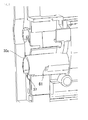
- the levers 63 of the shutter member 33 abuts on the lever engaging portions 55 of the unit connection groove 51 (see FIG. 14A ).
- the lever 63 abutting on the lever engaging portion 55 causes the shutter member 33 to rotate against the biasing force of the coil spring 62.
- the shutter member 33 is guided by the projection 61 engaged with the second opening 60, the slant portion 66, and the slant guide surface 301c to pivot counterclockwise in FIGS. 14A and 14B , while being slided toward the downstream side in the axis direction (see FIG. 14B ).
- the outlet 42 of the shutter member 33 allows the first opening 37 of the second cylindrical portion 30c to be communicated with the inlet 53 of the unit reception portion 52 (see FIG. 14B ). As this time, the shutter member 33 has moved to the open position P1.
- the shutter member 33 is dislocated upward along the unit connection groove 51.
- the shutter member 33 pivots in the opposite direction to the attachment direction by the biasing force of the coil spring 62. That is, by being guided by the second opening 60 and the slant portion 66, the shutter member 33 pivots (clockwise in FIGS. 14A and 14B ), while being slided toward the upstream side in the waste toner conveyance direction (see FIG. 14A ).
- the movement of the shutter member 33 from the open position P1 to the closed position P2 by the biasing force of the coil spring 62 is not stopped in an engaged state due to the projection 61 abutting on the end of the second opening 60, but is stopped in an engaged state due to the bottom surface of the shutter member 33 abutting on an end (side edge) 350 of the second cylindrical portion 30c.
- the shutter member 33 when the shutter member 33 is at the closed position P2, the bottom surface of the shutter member 33 and the end (side edge) 350 of the second cylindrical portion 30c are pressed against each other by the shutter opening/closing mechanism 34. This causes the end 350 of the second cylindrical portion 30c to be in close contact with and closed by the bottom surface of the shutter member 33.
Landscapes
- Physics & Mathematics (AREA)
- General Physics & Mathematics (AREA)
- Life Sciences & Earth Sciences (AREA)
- Engineering & Computer Science (AREA)
- Environmental & Geological Engineering (AREA)
- Sustainable Development (AREA)
- Cleaning In Electrography (AREA)
Abstract
Description
- The present disclosure relates to a toner conveying device for conveying toner, and an image forming apparatus.
- Generally, in an electrophotographic image forming apparatus such as a copier, printer or facsimile, an electrostatic latent image formed on an image carrier such as a photoconductor drum is visualized with developer (toner) in a developing device, and the toner image is transferred to a recording medium. In this process, toner that has not been transferred to the recording medium may remain on the surface of the photoconductor drum. As a result, a cleaning device removes the remaining toner (waste toner) from the surface of the photoconductor drum. The toner removed from the surface of the photoconductor drum is conveyed by a screw as the waste toner, and then recovered in a waste bottle.
- Meanwhile, the photoconductor drum, cleaning blade and the like have shorter lives than the image forming apparatus. As a result, these parts are normally provided as a unit that can be installed in the apparatus main body in an attachable/detachable manner as a replacement part (hereinafter, the unit is referred to as "cleaning unit"). In that case, an opening is formed in the cleaning unit to allow a waste toner conveyance path in the cleaning unit to communicate with the waste bottle.
- The cleaning unit is attached to and detached from the apparatus main body. As a result, when the cleaning unit is detached from the apparatus main body, it is necessary to prevent the waste toner remaining in the cleaning unit from leaking from the opening.
- There is known a conventional technology in which a shutter member is provided to open and close the opening. Specifically, an end of a casing of the cleaning unit on the downstream side in the conveyance path is formed in a shape of a cylinder, and the above-mentioned opening is formed in a lower part of the cylindrical portion. On the other hand, the shutter member is formed in the shape of a cup to be externally fitted with the cylindrical portion, and has an opening of a shape corresponding to the opening of the casing. In addition, the shutter member is configured to be rotated in the circumferential direction between a closing position and an opening position, wherein at the closing position, the opening of the casing is closed by the shutter member, and at the opening position, the opening of the casing overlaps with the opening of the shutter member, and the waste toner conveyance path in the cleaning unit is communicated with the waste bottle.
- A toner conveying device according to an aspect of the present disclosure includes a cylindrical member, a shutter member, and a shutter opening/closing mechanism. The cylindrical member is provided at an end of a toner conveyance path in which toner is conveyed, the cylindrical member having a first opening from which the toner is discharged, the end of the toner conveyance path being on a downstream side in a toner conveyance direction. The shutter member is formed in a shape of a cylinder with a bottom and configured to be externally fitted with the cylindrical member and open and close the first opening. The shutter opening/closing mechanism is configured to cause the shutter member to pivot between an open position at which the first opening is opened and a closed position at which the first opening is closed, while moving the shutter member in a direction along an axis around which the shutter member pivots such that at the closed position, a bottom surface of the shutter member and a side edge of the cylindrical member are pressed against each other.
- An image forming apparatus according to another aspect of the present disclosure includes a cleaning member, a cylindrical member, a shutter member, and a shutter opening/closing mechanism. The cleaning member is configured to remove toner from a surface of a photoconductor drum that carries a toner image. The cylindrical member is provided at a downstream-side end of a waste toner conveyance path in which waste toner removed by the cleaning member is conveyed, and has a first opening from which the waste toner is discharged, the downstream-side end being on a downstream side in a waste toner conveyance direction of the waste toner conveyance path. The shutter member is formed in a shape of a cylinder with a bottom and configured to be externally fitted with the cylindrical member and open and close the first opening. The shutter opening/closing mechanism is configured to cause the shutter member to pivot between positions of an open position at which the first opening is opened and a closed position at which the first opening is closed, while moving the shutter member in a direction along an axis around which the shutter member pivots such that at the closed position, a bottom surface of the shutter member and a side edge of the cylindrical member are pressed against each other.
- This Summary is provided to introduce a selection of concepts in a simplified form that are further described below in the Detailed Description with reference where appropriate to the accompanying drawings. This Summary is not intended to identify key features or essential features of the claimed subject matter, nor is it intended to be used to limit the scope of the claimed subject matter. Furthermore, the claimed subject matter is not limited to implementations that solve any or all disadvantages noted in any part of this disclosure.
-
-
FIG. 1 is a schematic cross sectional view showing the internal configuration of the image forming apparatus in an embodiment of the present disclosure. -
FIG. 2 is a schematic plan view showing the drum unit and the waste toner conveying device included in the image forming apparatus ofFIG. 1 . -
FIG. 3 is a perspective view showing the drum unit included in the image forming apparatus ofFIG. 1 . -
FIG. 4 is a cross sectional view showing the drum unit included in the image forming apparatus ofFIG. 1 . -
FIG. 5 is a cross sectional view showing the internal configuration of the cleaning unit included in the image forming apparatus ofFIG. 1 . -
FIG. 6 is a perspective view of an external appearance showing the configuration of the second cylindrical portion among the components of the casing of the cleaning unit. -
FIG. 7 is a perspective view of an external appearance showing the configuration of the second cylindrical portion seen in a different direction fromFIG. 6 . -
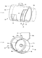
FIG. 8A is a perspective view, seen from a side, of the shutter member included in the cleaning unit ofFIG. 5 , andFIG. 8B is a perspective view thereof seen in the axis direction. -
FIG. 9 is a perspective view of a part of the shutter opening/closing mechanism included in the cleaning unit ofFIG. 5 . -
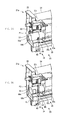
FIG. 10A is a perspective view of the peripheral of the shutter member when the shutter member is at an opening position, andFIG. 10B is a perspective view of the peripheral of the shutter member when the shutter member ofFIG. 8 is at a closing position. -
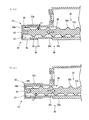
FIG. 11A is a cross sectional view of the peripheral of the shutter member when the shutter member is at the opening position, andFIG. 11B is a cross sectional view of the peripheral of the shutter member when the shutter member is at the closing position. -
FIGS. 12A and 12B are operation explanatory diagrams of the shutter opening/closing mechanism. -
FIG. 13 is a perspective view of the waste toner conveying device and the waste toner bottle included in the image forming apparatus ofFIG. 1 . -
FIGS. 14A and 14B are explanatory diagrams of the action of the shutter opening/closing mechanism when the cleaning unit ofFIG. 5 is attached and detached. -
FIGS. 15A and 15B are operation explanatory diagrams of the screw moving mechanism included in the cleaning unit ofFIG. 5 . -
FIGS. 16A and 16B are operation explanatory diagrams of the screw moving mechanism included in the cleaning unit ofFIG. 5 . - The following describes embodiments of the present disclusure with reference to the drawings. It should be noted that the following embodiments are only examples of specific embodiments of the present disclosure and should not limit the technical scope of the present disclosure. An image forming apparatus 1 shown in
FIG. 1 is an example of the image forming apparatus of the present disclosure. In the following description, a front direction Fr shown inFIG. 1 may be used for explanation. - As shown in
FIG. 1 , the image forming apparatus 1 is a multifunction peripheral having functions of a printer, a facsimile and the like. The image forming apparatus 1 prints an input image onto a print sheet by using a print material such as toner. It is noted that the image forming apparatus 1 is not limited to a multifunction peripheral, but may be an apparatus such as a printer, facsimile, or copier. - As shown in
FIG. 1 , the image forming apparatus 1 includes an apparatusmain body 2, asheet feed cassette 3, asheet discharge tray 5, asheet feed portion 11, an intermediate transfer unit 4, animage forming portion 21, asecondary transfer portion 14, and afixing portion 15. - The
sheet feed cassette 3 is provided in a lower part of the apparatusmain body 2, and configured to store a plurality of print sheets in a stacked state. Thesheet discharge tray 5 is provided on an upper surface of the apparatusmain body 2. Thesheet feed portion 11 supplies, one by one, the print sheets set in thesheet feed cassette 3 to aconveyance path 10. Theimage forming portion 21 primary-transfers a toner image onto anintermediate transfer belt 12 that is described below. Thesecondary transfer portion 14 secondary-transfers the toner image that has been temporarily transferred on theintermediate transfer belt 12, to a print sheet. The fixingportion 15 fixes, to the print sheet, the toner image that has been secondary-transferred to the print sheet. - The intermediate transfer unit 4 includes the
intermediate transfer belt 12, a drivingroller 12a, and atension roller 12b. Theintermediate transfer belt 12 is a belt having a shape of an endless loop and is made of rubber, urethane or other material. Theintermediate transfer belt 12 is wound around the drivingroller 12a and thetension roller 12b, and is run in the front direction Fr and in the opposite direction as the drivingroller 12a is driven and rotated by a driving motor (not shown). The drivingroller 12a is disposed close to the fixing portion 15 (on the right side inFIG. 1 ). Thetension roller 12b is disposed away from the fixing portion 15 (on the left side inFIG. 1 ). The surface of thetension roller 12b is made of rubber, urethane or other material that increases friction force with the drivingroller 12a. - The image forming apparatus 1 of the present embodiment is a so-called tandem color image forming apparatus, and includes a plurality of
image forming portions 21. The plurality ofimage forming portions 21 are aligned in the left-right direction inFIG. 1 . The plurality ofimage forming portions 21 form toner images of different colors, and in an order from the right inFIG. 1 , an image forming portion for black, an image forming portion for cyan, an image forming portion for magenta, and an image forming portion for yellow are arranged in a row. - The
image forming portions 21 form images using replenishing toner of a plurality of colors (Y, M, C, K) stored in a plurality oftoner containers 20. Each of theimage forming portions 21 includes aphotoconductor drum 24, a chargingportion 25, acleaning unit 26, a developingportion 27, and a primary transfer roller 28. Thephotoconductor drum 24 carries a toner image. The chargingportion 25 uniformly charges the surface of thephotoconductor drum 24. The developingportion 27 develops an electrostatic latent image on thephotoconductor drum 24 by using toner. The primary transfer roller 28 transfers the toner image from the surface of therotating photoconductor drum 24 to a movingintermediate transfer belt 12. Thecleaning unit 26 removes remaining waste toner from the surface of thephotoconductor drum 24. Anexposure portion 22 is provided below theimage forming portion 21. Theexposure portion 22 forms the electrostatic latent image by exposing the charged surface of thephotoconductor drum 24 to scanning light. Thetoner containers 20 that are aligned below thesheet discharge tray 5 have been installed in the apparatusmain body 2 each in an attachable/detachable manner. - In the image forming apparatus 1 having the above-described configuration, the surface of the
photoconductor drum 24 is uniformly charged by the chargingportion 25. Theexposure portion 22 performs exposure on thephotoconductor drum 24 based on image data. With this exposure, an electrostatic latent image is formed on the surface of thephotoconductor drum 24. The developingportion 27 then visualizes the electrostatic latent image (forms a toner image) by using toner supplied from thetoner containers 20. - When a bias is applied to the primary transfer roller 28, the toner image formed on the surface of the
photoconductor drum 24 is transferred to the surface of the runningintermediate transfer belt 12. The waste toner that has remained on the surface of thephotoconductor drum 24 is removed by thecleaning unit 26. These operations are performed in theimage forming portions 21 in sequence, and a color toner image is formed on the surface of theintermediate transfer belt 12. - On the other hand, the print sheet supplied by the
sheet feed portion 11 from thesheet feed cassette 3 is passed through theconveyance path 10 and conveyed to thesecondary transfer portion 14. When a bias is applied to thesecondary transfer portion 14, the color toner image formed on the surface of theintermediate transfer belt 12 is secondary-transferred to the print sheet. Subsequently, the print sheet is subjected to a fixing process by the fixingportion 15, and is ejected onto thesheet discharge tray 5. - The
photoconductor drum 24, chargingportion 25, and cleaningunit 26 are provided as a unit. This unit is referred to as adrum unit 21a. The following explains a movement path of the waste toner removed from thephotoconductor drum 24. - As shown in
FIG. 2 , the waste toner removed from thephotoconductor drum 24 in eachdrum unit 21a drops to a first conveyance path 36 (seeFIG. 4 ) of each cleaningunit 26, thefirst conveyance path 36 being described below. The waste toner accumulated in thefirst conveyance path 36 is conveyed in the downstream direction toward afirst opening 37 by the rotation of afirst screw member 32 provided in a casing 30 (seeFIG. 3 ) of thecleaning unit 26. - The image forming apparatus 1 includes a waste
toner conveying device 50 that conveys, into awaste toner bottle 59, the waste toner that has been conveyed by thecleaning units 26. The wastetoner conveying device 50 is configured to be connected with the cleaningunits 26 that are arranged in the front-rear direction of the image forming apparatus 1. - In the waste
toner conveying device 50, asecond conveyance path 56 extends in the front-rear direction. Thesecond conveyance path 56 includesinlets 53 for introducing the waste toner from therespective cleaning units 26. Asecond screw member 57 is disposed in thesecond conveyance path 56. Thesecond screw member 57 has the same configuration as thefirst screw member 32. The opposite ends of thesecond screw member 57 in the axis direction are rotatably supported by the inner wall of thesecond conveyance path 56. Thesecond screw member 57 is driven and rotated by a driving motor (not shown). Asecond outlet 58 is formed at a downstream-side end of thesecond conveyance path 56. Thesecond outlet 58 communicates with thewaste toner bottle 59. As described below, the image forming apparatus 1 of the present embodiment includes ashutter member 33 that, as described below, plays a role in the communication and blockage between thefirst conveyance path 36 in thecleaning unit 26 and thesecond conveyance path 56 in the wastetoner conveying device 50. The following describes specific configuration of each portion. - As shown in
FIGS. 3 and4 , thephotoconductor drum 24 is rotatably supported by a pair of supportingframes 23 provided at the opposite ends of thedrum unit 21a in the axis direction. Adrum driving gear 24b is attached to an upstream-side end (the right end inFIG. 3 ) of thephotoconductor drum 24, with a supportingframe 23 therebetween. Thedrum driving gear 24b meshes with adriving gear 29 that is driven and rotated by a driving motor (not shown) (seeFIGS. 15A and 15B ). When thedrum driving gear 24b is driven by the driving motor, thephotoconductor drum 24 is driven and rotated via the mesh of thedrum driving gear 24b and thedriving gear 29. - As shown in
FIG. 4 , the chargingportion 25 includes a chargingroller 25a and a rubbingroller 25b. The chargingroller 25a slidably contacts thephotoconductor drum 24. The rubbingroller 25b polishes the surface of the chargingroller 25a. - As shown in
FIGS. 3 and4 , thecleaning unit 26 includes thecasing 30, a cleaningmember 31, thefirst screw member 32, theshutter member 33, a shutter opening/closing mechanism 34, and ascrew moving mechanism 35. Here, thecleaning unit 26 is an example of the toner conveying device of the present disclosure. More specifically, a secondcylindrical portion 30c (described below), theshutter member 33, and the shutter opening/closing mechanism 34 that are included in thecasing 30 configure the toner conveying device of the present disclosure. - The
casing 30 supports the cleaningmember 31 and the like. Thecasing 30 includes a casingmain body 30a, a firstcylindrical portion 30b, and the secondcylindrical portion 30c. The casingmain body 30a extends along the axis direction of thephotoconductor drum 24, and has an opening on thephotoconductor drum 24 side. As shown inFIG. 3 , the casingmain body 30a is shorter than thephotoconductor drum 24 in length in the axis direction, and is supported by the supportingframes 23 via connectingarms 30d at the opposite ends of thedrum unit 21a. - The first
cylindrical portion 30b and the secondcylindrical portion 30c are each formed in the shape of a cylinder. The firstcylindrical portion 30b projects outward from an upstream-side end (the right end inFIG. 3 ) of the casingmain body 30a. The secondcylindrical portion 30c projects outward from a downstream-side end (the left end inFIG. 3 ) of the casingmain body 30a. As shown inFIGS. 6 and7 , a part of an end of the secondcylindrical portion 30c is cut to form thefirst opening 37 that is communicable with thefirst conveyance path 36. - In addition, as shown in
FIG. 6 , aslant guide surface 301c is formed on an end of the secondcylindrical portion 30c at a position different from the position of the cut in the circumferential direction, wherein theslant guide surface 301c is a slant surface that extends slanting with respect to the circumferential direction of the secondcylindrical portion 30c. A slant portion 66 (described below) of theshutter member 33 slidably contacts theslant guide surface 301c. Upon the contact, theslant guide surface 301c guides theshutter member 33 to pivot around the axis and move in the axis direction. As shown inFIG. 7 , aprojection 61 is provided on an outer circumferential surface of the secondcylindrical portion 30c. The secondcylindrical portion 30c is an example of the cylindrical member. As shown inFIG. 5 , thefirst conveyance path 36 for conveying the waste toner is defined by the firstcylindrical portion 30b, casingmain body 30a, and secondcylindrical portion 30c. - As shown in
FIGS. 3 and4 , the cleaningmember 31 includes acleaning roller 31a and acleaning blade 31b. - The opposite ends of the cleaning
roller 31a in the axis direction are rotatably supported by the casingmain body 30a. A part of the circumferential surface of the cleaningroller 31a abuts on the surface of thephotoconductor drum 24 via the opening of thecasing 30. The cleaningroller 31a is driven and rotated by a driving motor (not shown) in an opposite direction to thephotoconductor drum 24, thereby removing the waste toner that has remained on the surface of thephotoconductor drum 24 after transferring of a toner image to the primary transfer roller 28. - The
cleaning blade 31b is provided below the cleaningroller 31a. Thecleaning blade 31b is made of urethane rubber or other material and is elastic. An upper part of the cleaningroller 31a is a free end and is elastically pressed against the surface of thephotoconductor drum 24. With this configuration, the waste toner on the surface of thephotoconductor drum 24 is scraped. In this way, the cleaningmember 31 removes toner from the surface of thephotoconductor drum 24 that carries the toner image. - As shown in
FIGS. 4 and5 , thefirst screw member 32 conveys the waste toner in thefirst conveyance path 36 formed in thecasing 30. Thefirst screw member 32 includes arotary shaft 32a and ahelical vane 32b. Therotary shaft 32a extends along thefirst conveyance path 36. Thehelical vane 32b is helically formed on the circumferential surface of therotary shaft 32a. Thefirst screw member 32 passes through the firstcylindrical portion 30b and extends toward the upstream side. A driven gear 41 (seeFIG. 3 ) is attached to an upstream-side end of thefirst screw member 32. - As shown in
FIGS. 8A and 8B , theshutter member 33 has a shape of a cylinder with a bottom, and is externally fitted with the secondcylindrical portion 30c (seeFIGS. 11A and 11B ). Theshutter member 33 opens and closes thefirst opening 37 of the secondcylindrical portion 30c. Arectangular outlet 42 is formed in acircumferential wall 33a of theshutter member 33. As shown inFIG. 8B , a cylindrical downstream-side bearing 43 is formed on aninner surface 66b of abottom wall 33b of theshutter member 33. The downstream-side bearing 43 rotatably supports a downstream-side end of thefirst screw member 32. The downstream-side bearing 43 projects toward the upstream side in the axis direction from the center of the inner surface of theshutter member 33, and is fitted with therotary shaft 32a of thefirst screw member 32 in an insertable/removable manner. It is noted that, as shown inFIGS. 3 and5 , an upstream-side bearing 38 is formed at a part where the casingmain body 30a is connected with the firstcylindrical portion 30b, and the upstream-side bearing 38 rotatably supports an upstream-side end of thefirst screw member 32. As a result, the opposite ends of thefirst screw member 32 are pivotally supported by the upstream-side bearing 38 and the downstream-side bearing 43 of theshutter member 33. - The
circumferential wall 33a of theshutter member 33 includes asecond opening 60 and alever 63. - The
second opening 60 is formed at an upstream of theoutlet 42 on thecircumferential wall 33a of theshutter member 33. Thesecond opening 60 extends slanting with respect to the circumferential direction of thecircumferential wall 33a. In addition, thesecond opening 60 is formed in a rectangular shape of the same width that slants such that it goes away from thebottom wall 33b of theshutter member 33 as it goes toward the upstream side. Thesecond opening 60 is engaged with theprojection 61 of the secondcylindrical portion 30c. Theprojection 61 relatively moves in thesecond opening 60 as theshutter member 33 rotates around the axis. The engagement of thesecond opening 60 and theprojection 61 of the secondcylindrical portion 30c prevents theshutter member 33 from dropping off from the secondcylindrical portion 30c in movement in the axis direction. - A
thin wall 64 is formed adjacent to thesecond opening 60, defining the upstream side of thesecond opening 60, wherein thethin wall 64 is slightly thinner than thecircumferential wall 33a of theshutter member 33. Thethin wall 64 has approximately the same width as thesecond opening 60. Acut 65 is formed slantly along thethin wall 64 on the opening side of theshutter member 33. - In addition, as shown in
FIG. 8B , aslant portion 66 is formed on theinner surface 66b of thebottom wall 33b of theshutter member 33. Theslant portion 66 includes aslant surface 66a that is slanted in the same direction and at the same angle as thesecond opening 60 with respect to the circumferential direction of thecircumferential wall 33a. Theslant portion 66 is formed at a position that is different from the position of thesecond opening 60 in the circumferential direction. Theslant portion 66 abuts on theslant guide surface 301c of the secondcylindrical portion 30c, and slidably contacts theslant guide surface 301c when theshutter member 33 rotates around the axis. - As described above, in the present embodiment, the
shutter member 33's rotation around the axis and movement in the axis direction are guided by the abutment of theslant portion 66 of theshutter member 33 and theslant guide surface 301c of the secondcylindrical portion 30c, and by the engagement of thesecond opening 60 with theprojection 61 of the secondcylindrical portion 30c. - As shown in
FIG. 8B , thelever 63 projects from the outer circumferential surface of thecircumferential wall 33a. In thelever 63, a lockingportion 63a is formed as a recess that is recessed in the circumferential direction. An end of acoil spring 62 that is described below is locked to the lockingportion 63a. In addition, a part of thelever 63 opposite to the lockingportion 63a is a flatabutting portion 63b. When thecleaning unit 26 is installed in the image forming apparatus 1, the abuttingportion 63b contacts a lever engaging portion 55 (an example of the predetermined contact portion on the image forming apparatus 1 side), and thereby receives an external force that allows theshutter member 33 to pivot from a closed position P2 to an open position P1. - As shown in
FIG. 5 , the image forming apparatus 1 of the present embodiment is provided with the shutter opening/closing mechanism 34. - As shown in
FIG. 9 , the shutter opening/closing mechanism 34 is composed of thesecond opening 60 and thelever 63 formed on thecircumferential wall 33a of theshutter member 33, and theprojection 61 and thecoil spring 62 formed on the secondcylindrical portion 30c. - The shutter opening/
closing mechanism 34 moves theshutter member 33 in the axis direction between the open position P1 and the closed position P2. The open position P1, is shown inFIGS. 10A ,11A and12A , and the closed position P2, is shown inFIGS. 10B ,11B and12B . When theshutter member 33 is at the open position P1, theoutlet 42 of theshutter member 33 and thefirst opening 37 of the secondcylindrical portion 30c overlap with each other, and thefirst opening 37 communicates with thesecond conveyance path 56. When theshutter member 33 is at the closed position P2, theoutlet 42 of theshutter member 33 and thefirst opening 37 of the secondcylindrical portion 30c are at different positions, and thefirst opening 37 is closed by theshutter member 33. - The
second opening 60 formed in theshutter member 33 is engaged with theprojection 61 formed on the secondcylindrical portion 30c. In addition, theslant portion 66 of theshutter member 33 abuts on theslant guide surface 301c formed at the downstream-side end of the secondcylindrical portion 30c. As a result, the movement of theshutter member 33 in the axis direction between the open position P1 and the closed position P2 involves a rotation around the axis. In addition, the closed position P2 is on the upstream side of the open position P1 in the axis direction. - As described above, the shutter opening/
closing mechanism 34 allows theshutter member 33 to pivot between the open position P1 for thefirst opening 37 to be opened and the closed position P2 for thefirst opening 37 to be closed, while allowing theshutter member 33 to move in a direction along an axis around which theshutter member 33 pivots. - Meanwhile, the following problem occurs when such configuration of the
shutter member 33 is adopted. That is, a predetermined gap is provided between the inner circumferential surface of theshutter member 33 and the outer circumferential surface of the secondcylindrical portion 30c to ensure a smooth rotation of theshutter member 33 with respect to the secondcylindrical portion 30c. As a result, when thecleaning unit 26 is removed from the apparatusmain body 2, the waste toner may leak outside from the gap between theshutter member 33 and the end of thecasing 30. - As shown in
FIG. 9 , thecoil spring 62 functions as a biasing member that biases theshutter member 33 and dislocates theshutter member 33 from the open position P1 to the closed position P2 in the pivoting direction. Thecoil spring 62 is wound around theshutter member 33, covering thesecond opening 60 as a prevention of waste toner leakage. Anend 62a of thecoil spring 62 is locked to a supportingframe 23 on the downstream side, and the other end of thecoil spring 62 is locked to thelever 63 of theshutter member 33. With this configuration, thecoil spring 62 biases theshutter member 33 toward the closed position P2 in the pivoting direction, namely, in the counterclockwise direction inFIGS. 11A and 11B . - As shown in
FIG. 13 , a plurality ofunit connection grooves 51 are formed on the wastetoner conveying device 50 at equal intervals. Thefirst openings 37 of thecleaning units 26 are respectively connected to the plurality ofunit connection grooves 51. Eachunit connection groove 51 has a similar configuration to each other, extending from above to below. Theshutter member 33 of each cleaningunit 26 is inserted to eachunit connection groove 51 from above. - A
unit reception portion 52 is formed on the bottom of eachunit connection groove 51, theunit reception portion 52 having a shape that corresponds to the shape of theshutter member 33. Therectangular inlet 53 is formed in theunit reception portion 52. When thecleaning unit 26 is attached to the wastetoner conveying device 50, theoutlet 42 formed on theshutter member 33 allows thefirst opening 37 of the secondcylindrical portion 30c to communicate with theinlet 53 of the unit reception portion 52 (seeFIG. 14B ). - The portion of the
unit reception portion 52 other than theinlet 53 is composed of aseal 54 that is made of an elastic material such as synthetic rubber. When thecleaning unit 26 is attached to the wastetoner conveying device 50, lower parts of thecircumferential wall 33a and thebottom wall 33b including the rim of theoutlet 42 of theshutter member 33 are sealed by theseal 54. - As shown in
FIG. 13 , alever engaging portion 55 is formed on a side of eachunit connection groove 51. Thelever engaging portion 55 is provided on an upper part of theunit reception portion 52. When thecleaning unit 26 is attached to the wastetoner conveying device 50, thecleaning unit 26 is temporarily engaged with thelever 63 provided on thecircumferential wall 33a of theshutter member 33. - As the
first screw member 32 rotates, the waste toner is conveyed in the downstream direction toward thefirst opening 37 and theoutlet 42, passes theinlet 53 that is connected with theoutlet 42 via theseal 54, and flows into the second conveyance path 56 (see the arrows inFIG. 13 ). Furthermore, as thesecond screw member 57 rotates, the waste toner having flown into thesecond conveyance path 56 is conveyed toward thesecond outlet 58 on the downstream side, passes through arecovery port 59a that communicates with thesecond outlet 58, and is recovered into the waste toner bottle 59 (see the white arrows inFIG. 13 ). - As shown in
FIG. 5 , thescrew moving mechanism 35 is provided at an end of thecleaning unit 26 opposite to the shutter opening/closing mechanism 34, and moves thefirst screw member 32 in the same direction (the axis direction) as theshutter member 33 in conjunction with the movement of theshutter member 33 by the shutter opening/closing mechanism 34. - As shown in
FIGS. 15A through 16B , thescrew moving mechanism 35 includes thedriving gear 29, the drivengear 41, and the coil spring 62 (seeFIG. 9 ). Thedriving gear 29 rotates thephotoconductor drum 24 via thedrum driving gear 24b (seeFIG. 3 ). The drivengear 41 meshes thedriving gear 29 and rotates thefirst screw member 32. Thedriving gear 29 and the drivengear 41 are helical gears. - When the driving motor (not shown) is driven to totate the
driving gear 29, thrust load toward the downstream (the left side inFIG. 13 ) acts on the drivengear 41 meshing with thedriving gear 29. Upon receiving this, the drivengear 41 causes the thrust load to act on thefirst screw member 32 so that theshutter member 33 is moved to the open position P1. As a result, as shown inFIGS. 11A ,12A and15A , thefirst screw member 32 moves toward the downstream side in the axis direction. - When the driving force is not acting on the
driving gear 29, the thrust load does not occur, and as shown inFIGS. 15B and16B , thefirst screw member 32 is in the state where it can move toward the upstream side in the axis direction together with theshutter member 33 by the biasing force of thecoil spring 62. - When a
drum unit 21a is attached to the apparatusmain body 2, the apparatusmain body 2 is opened and theunit connection grooves 51 of the wastetoner conveying device 50 are exposed, and theshutter member 33 of thecleaning unit 26 is entered (inserted) into a correspondingunit connection groove 51 in a direction from above to below. - As the entering of the
shutter member 33 into theunit connection groove 51 proceeds, thelevers 63 of theshutter member 33 abuts on thelever engaging portions 55 of the unit connection groove 51 (seeFIG. 14A ). As theshutter member 33 further enters, thelever 63 abutting on thelever engaging portion 55 causes theshutter member 33 to rotate against the biasing force of thecoil spring 62. At this time, theshutter member 33 is guided by theprojection 61 engaged with thesecond opening 60, theslant portion 66, and theslant guide surface 301c to pivot counterclockwise inFIGS. 14A and 14B , while being slided toward the downstream side in the axis direction (seeFIG. 14B ). - When the
shutter member 33 reaches theunit reception portion 52, theoutlet 42 of theshutter member 33 allows thefirst opening 37 of the secondcylindrical portion 30c to be communicated with theinlet 53 of the unit reception portion 52 (seeFIG. 14B ). As this time, theshutter member 33 has moved to the open position P1. - On the other hand, when the
drum unit 21a connected to the wastetoner conveying device 50 is pulled upward, theshutter member 33 is dislocated upward along theunit connection groove 51. As the upward dislocation of theshutter member 33 proceeds, theshutter member 33 pivots in the opposite direction to the attachment direction by the biasing force of thecoil spring 62. That is, by being guided by thesecond opening 60 and theslant portion 66, theshutter member 33 pivots (clockwise inFIGS. 14A and 14B ), while being slided toward the upstream side in the waste toner conveyance direction (seeFIG. 14A ). - Here, in the present embodiment, as shown in
FIGS. 12A and 12B , the movement of theshutter member 33 from the open position P1 to the closed position P2 by the biasing force of thecoil spring 62 is not stopped in an engaged state due to theprojection 61 abutting on the end of thesecond opening 60, but is stopped in an engaged state due to the bottom surface of theshutter member 33 abutting on an end (side edge) 350 of the secondcylindrical portion 30c. - That is, when the
shutter member 33 is at the closed position P2, the bottom surface of theshutter member 33 and the end (side edge) 350 of the secondcylindrical portion 30c are pressed against each other by the shutter opening/closing mechanism 34. This causes theend 350 of the secondcylindrical portion 30c to be in close contact with and closed by the bottom surface of theshutter member 33. - As a result, even if a gap exists between the
shutter member 33 and the secondcylindrical portion 30c that are fitted with each other, it is possible, when thedrum unit 21a is removed from the image forming apparatus 1, to prevent the waste toner that has remained in thecasing 30 from leaking outside from the gap. As a result, for example, there is no need to provide a seal member between theshutter member 33 and the secondcylindrical portion 30c, thereby enabling the number of parts to be reduced. - It is to be understood that the embodiments herein are illustrative and not restrictive, since the scope of the disclosure is defined by the appended claims rather than by the description preceding them, and all changes that fall within metes and bounds of the claims, or equivalence of such metes and bounds thereof are therefore intended to be embraced by the claims.
Claims (5)
- A toner conveying device (26) comprising:a cylindrical member (30c) provided at an end of a toner conveyance path in which toner is conveyed, the cylindrical member (30c) having a first opening (37) from which the toner is discharged, the end of the toner conveyance path being on a downstream side in a toner conveyance direction;a shutter member (33) formed in a shape of a cylinder with a bottom and configured to be externally fitted with the cylindrical member (30c) and open and close the first opening (37); anda shutter opening/closing mechanism (34) configured to cause the shutter member (33) to pivot between an open position at which the first opening (37) is opened and a closed position at which the first opening (37) is closed, while moving the shutter member (33) in a direction along an axis around which the shutter member (33) pivots such that at the closed position, a bottom surface of the shutter member (33) and a side edge of the cylindrical member (30c) are pressed against each other.
- The toner conveying device (26) according to claim 1, wherein
the shutter opening/closing mechanism (34) includes a biasing member (62) configured to bias the shutter member (33) from the open position to the closed position, and
the movement of the shutter member (33) from the open position to the closed position by a biasing force of the biasing member (62) is stopped in an engaged state by the side edge of the cylindrical member (30c), thereby at the closed position, the bottom surface of the shutter member (33) is pressed against the side edge of the cylindrical member (30c). - The toner conveying device (26) according to claim 2, wherein
the shutter opening/closing mechanism (34) further includes a second opening (60) and a projection (61), the second opening (60) being provided on an outer circumferential surface of the shutter member (33) and slanting with respect to a circumferential direction of the shutter member (33), the projection (61) being provided on an outer circumferential surface of the cylindrical member (30c) and configured to be engaged with the second opening (60), and
the biasing member (62) biases the shutter member (33) to dislocate the shutter member (33) from the open position to the closed state in the direction along the axis around which the shutter member (33) pivots. - The toner conveying device (26) according to claim 3, wherein
the shutter opening/closing mechanism (34) further includes a lever that projects from the outer circumferential surface of the shutter member (33), and when a cleaning device (21) is attached to an image forming apparatus (1), contacts a predetermined contact portion on the image forming apparatus (1) side, and thereby receives an external force that allows the shutter member (33) to pivot from the closed position to the open position. - An image forming apparatus (1) comprising:a cleaning member (31) configured to remove toner from a surface of a photoconductor drum (24) that carries a toner image;a cylindrical member (30c) provided at an end of a waste toner conveyance path in which waste toner removed by the cleaning member is conveyed, the cylindrical member (30c) having a first opening (37) from which the toner is discharged, the end of the waste toner conveyance path being on a downstream side in a waste toner conveyance direction;a shutter member (33) formed in a shape of a cylinder with a bottom and configured to be externally fitted with the cylindrical member (30c) and open and close the first opening (37); anda shutter opening/closing mechanism (34) configured to cause the shutter member (33) to pivot between an open position at which the first opening (37) is opened and a closed position at which the first opening (37) is closed, while moving the shutter member (33) in a direction along an axis around which the shutter member (33) pivots such that at the closed position, a bottom surface of the shutter member (33) and a side edge of the cylindrical member (30c) are pressed against each other.
Applications Claiming Priority (1)
| Application Number | Priority Date | Filing Date | Title |
|---|---|---|---|
| JP2013264375A JP5933516B2 (en) | 2013-12-20 | 2013-12-20 | Cleaning device, image forming device |
Publications (1)
| Publication Number | Publication Date |
|---|---|
| EP2887148A1 true EP2887148A1 (en) | 2015-06-24 |
Family
ID=52231836
Family Applications (1)
| Application Number | Title | Priority Date | Filing Date |
|---|---|---|---|
| EP14197884.1A Withdrawn EP2887148A1 (en) | 2013-12-20 | 2014-12-15 | Toner conveying device, image forming apparatus |
Country Status (4)
| Country | Link |
|---|---|
| US (1) | US9239545B2 (en) |
| EP (1) | EP2887148A1 (en) |
| JP (1) | JP5933516B2 (en) |
| CN (1) | CN104730892A (en) |
Families Citing this family (8)
| Publication number | Priority date | Publication date | Assignee | Title |
|---|---|---|---|---|
| JP6134689B2 (en) * | 2014-06-03 | 2017-05-24 | 京セラドキュメントソリューションズ株式会社 | Image carrier unit and image forming apparatus having the same |
| JP2016186544A (en) * | 2015-03-27 | 2016-10-27 | 富士ゼロックス株式会社 | Developer discharge structure and image forming apparatus |
| JP6784064B2 (en) * | 2016-06-01 | 2020-11-11 | 富士ゼロックス株式会社 | Powder transfer device and image forming device |
| KR20190036322A (en) * | 2017-09-27 | 2019-04-04 | 에이치피프린팅코리아 유한회사 | developing device and electrophotographic image forming apparatus using the same |
| US10394164B1 (en) * | 2018-02-09 | 2019-08-27 | Kabushiki Kaisha Toshiba | Angled ridges on electrostatic process unit shafts |
| CN108508724B (en) * | 2018-04-03 | 2024-09-13 | 珠海天威飞马打印耗材有限公司 | Toner container and method for opening and closing a toner outlet on the toner container |
| JP7625798B2 (en) * | 2020-06-29 | 2025-02-04 | ブラザー工業株式会社 | Image forming device |
| CN111930001A (en) * | 2020-08-24 | 2020-11-13 | 江西凯利德科技有限公司 | Developing box conductive separation structure and developing box using same |
Citations (4)
| Publication number | Priority date | Publication date | Assignee | Title |
|---|---|---|---|---|
| JPH09146432A (en) * | 1995-09-18 | 1997-06-06 | Mita Ind Co Ltd | Toner recovering device for image forming equipment |
| EP1659456A2 (en) * | 2004-11-12 | 2006-05-24 | Canon Kabushiki Kaisha | Cartridge for image forming apparatus |
| US20140321896A1 (en) * | 2013-04-26 | 2014-10-30 | Kyocera Document Solutions Inc. | Cleaning unit, image forming apparatus including the same, and shutter provided in cleaning unit |
| EP2811344A1 (en) * | 2012-01-31 | 2014-12-10 | Kyocera Document Solutions Inc. | Image formation device and toner container |
Family Cites Families (11)
| Publication number | Priority date | Publication date | Assignee | Title |
|---|---|---|---|---|
| JP3966639B2 (en) * | 1999-03-31 | 2007-08-29 | 株式会社沖データ | Image recording device |
| JP4137825B2 (en) * | 2004-03-17 | 2008-08-20 | シャープ株式会社 | Powder replenishing apparatus and image forming apparatus |
| JP4409569B2 (en) * | 2006-12-28 | 2010-02-03 | 株式会社沖データ | Image recording device |
| JP4478705B2 (en) * | 2007-08-28 | 2010-06-09 | シャープ株式会社 | Toner transport unit and image forming apparatus |
| JP2009276626A (en) * | 2008-05-15 | 2009-11-26 | Murata Mach Ltd | Toner container |
| JP2010256741A (en) | 2009-04-28 | 2010-11-11 | Kyocera Mita Corp | Drum unit and image forming apparatus equipped therewith |
| JP5213945B2 (en) * | 2009-12-24 | 2013-06-19 | キヤノンファインテック株式会社 | Toner recovery device, cartridge, and image forming apparatus |
| JP5003779B2 (en) * | 2010-03-19 | 2012-08-15 | コニカミノルタビジネステクノロジーズ株式会社 | Developing device and image forming apparatus |
| JP5033897B2 (en) * | 2010-05-13 | 2012-09-26 | シャープ株式会社 | Shutter device, waste toner collecting unit, and image forming apparatus |
| JP5205426B2 (en) * | 2010-08-26 | 2013-06-05 | 京セラドキュメントソリューションズ株式会社 | Image forming apparatus |
| JP2013068752A (en) * | 2011-09-21 | 2013-04-18 | Fuji Xerox Co Ltd | Detachably opening/closing structure, and image forming device having the same |
-
2013
- 2013-12-20 JP JP2013264375A patent/JP5933516B2/en active Active
-
2014
- 2014-12-15 CN CN201410775594.3A patent/CN104730892A/en active Pending
- 2014-12-15 EP EP14197884.1A patent/EP2887148A1/en not_active Withdrawn
- 2014-12-16 US US14/572,657 patent/US9239545B2/en active Active
Patent Citations (4)
| Publication number | Priority date | Publication date | Assignee | Title |
|---|---|---|---|---|
| JPH09146432A (en) * | 1995-09-18 | 1997-06-06 | Mita Ind Co Ltd | Toner recovering device for image forming equipment |
| EP1659456A2 (en) * | 2004-11-12 | 2006-05-24 | Canon Kabushiki Kaisha | Cartridge for image forming apparatus |
| EP2811344A1 (en) * | 2012-01-31 | 2014-12-10 | Kyocera Document Solutions Inc. | Image formation device and toner container |
| US20140321896A1 (en) * | 2013-04-26 | 2014-10-30 | Kyocera Document Solutions Inc. | Cleaning unit, image forming apparatus including the same, and shutter provided in cleaning unit |
Also Published As
| Publication number | Publication date |
|---|---|
| JP5933516B2 (en) | 2016-06-08 |
| US20150177648A1 (en) | 2015-06-25 |
| JP2015121613A (en) | 2015-07-02 |
| US9239545B2 (en) | 2016-01-19 |
| CN104730892A (en) | 2015-06-24 |
Similar Documents
| Publication | Publication Date | Title |
|---|---|---|
| US9239545B2 (en) | Toner conveying device, image forming apparatus | |
| JP4525782B2 (en) | Developer container and image forming apparatus | |
| EP2913719B1 (en) | Image forming apparatus | |
| CN107407904B (en) | Cartridges, process cartridges and imaging units | |
| CN104122779B (en) | Cleaning unit, the image processing system with this cleaning unit and the gate being arranged on cleaning unit | |
| US9395648B2 (en) | Toner accommodating container and image forming apparatus | |
| US20110305486A1 (en) | Toner conveying apparatus, toner cartridge and cleaning unit having the toner conveying apparatus | |
| WO2012176722A1 (en) | Image formation device | |
| JP2008116479A (en) | Image forming apparatus | |
| JP6090026B2 (en) | Waste toner collection container | |
| JP5961575B2 (en) | Toner transport mechanism and image forming apparatus | |
| US9182702B2 (en) | Toner case for image forming apparatus | |
| US20130121721A1 (en) | Developer conveyance apparatus developing apparatus and process cartridge | |
| US20170219956A1 (en) | Image forming apparatus | |
| JP5372185B2 (en) | Process cartridge and electrophotographic image forming apparatus | |
| US9280091B2 (en) | Toner conveying device and image forming apparatus including the same | |
| JP5929615B2 (en) | Image forming apparatus | |
| JP2015129892A (en) | Attaching/detaching mechanism of charging roller, and image forming apparatus including the same | |
| JP6132197B2 (en) | Image forming apparatus | |
| CN109581838B (en) | Developing device and image forming apparatus | |
| JP6659128B2 (en) | Image forming device | |
| JP6566783B2 (en) | Image forming apparatus | |
| JP4978029B2 (en) | Image forming apparatus | |
| JP2015114398A (en) | Image forming apparatus | |
| JP6463006B2 (en) | Image forming apparatus |
Legal Events
| Date | Code | Title | Description |
|---|---|---|---|
| PUAI | Public reference made under article 153(3) epc to a published international application that has entered the european phase |
Free format text: ORIGINAL CODE: 0009012 |
|
| 17P | Request for examination filed |
Effective date: 20141215 |
|
| AK | Designated contracting states |
Kind code of ref document: A1 Designated state(s): AL AT BE BG CH CY CZ DE DK EE ES FI FR GB GR HR HU IE IS IT LI LT LU LV MC MK MT NL NO PL PT RO RS SE SI SK SM TR |
|
| AX | Request for extension of the european patent |
Extension state: BA ME |
|
| R17P | Request for examination filed (corrected) |
Effective date: 20151222 |
|
| RBV | Designated contracting states (corrected) |
Designated state(s): AL AT BE BG CH CY CZ DE DK EE ES FI FR GB GR HR HU IE IS IT LI LT LU LV MC MK MT NL NO PL PT RO RS SE SI SK SM TR |
|
| 17Q | First examination report despatched |
Effective date: 20180131 |
|
| STAA | Information on the status of an ep patent application or granted ep patent |
Free format text: STATUS: THE APPLICATION IS DEEMED TO BE WITHDRAWN |
|
| 18D | Application deemed to be withdrawn |
Effective date: 20180612 |