EP2887147A1 - Printing device and method - Google Patents
Printing device and method Download PDFInfo
- Publication number
- EP2887147A1 EP2887147A1 EP14193169.1A EP14193169A EP2887147A1 EP 2887147 A1 EP2887147 A1 EP 2887147A1 EP 14193169 A EP14193169 A EP 14193169A EP 2887147 A1 EP2887147 A1 EP 2887147A1
- Authority
- EP
- European Patent Office
- Prior art keywords
- temperature
- fuser
- printing device
- signal
- threshold voltage
- Prior art date
- Legal status (The legal status is an assumption and is not a legal conclusion. Google has not performed a legal analysis and makes no representation as to the accuracy of the status listed.)
- Withdrawn
Links
- 238000007639 printing Methods 0.000 title claims abstract description 81
- 238000000034 method Methods 0.000 title claims description 19
- 230000011664 signaling Effects 0.000 claims description 2
- 230000006870 function Effects 0.000 description 13
- 238000012545 processing Methods 0.000 description 13
- 238000010438 heat treatment Methods 0.000 description 9
- 101100102849 Saccharomyces cerevisiae (strain ATCC 204508 / S288c) VTH1 gene Proteins 0.000 description 6
- 230000008569 process Effects 0.000 description 6
- 238000010586 diagram Methods 0.000 description 4
- 238000007599 discharging Methods 0.000 description 3
- 238000012546 transfer Methods 0.000 description 3
- 101150088150 VTH2 gene Proteins 0.000 description 2
- 238000004891 communication Methods 0.000 description 2
- 238000004590 computer program Methods 0.000 description 2
- 230000004913 activation Effects 0.000 description 1
- 230000008901 benefit Effects 0.000 description 1
- 238000007796 conventional method Methods 0.000 description 1
- 238000005516 engineering process Methods 0.000 description 1
- 229910052736 halogen Inorganic materials 0.000 description 1
- 150000002367 halogens Chemical class 0.000 description 1
- 238000012986 modification Methods 0.000 description 1
- 230000004048 modification Effects 0.000 description 1
- 238000010408 sweeping Methods 0.000 description 1
Images


Classifications
-
- G—PHYSICS
- G03—PHOTOGRAPHY; CINEMATOGRAPHY; ANALOGOUS TECHNIQUES USING WAVES OTHER THAN OPTICAL WAVES; ELECTROGRAPHY; HOLOGRAPHY
- G03G—ELECTROGRAPHY; ELECTROPHOTOGRAPHY; MAGNETOGRAPHY
- G03G15/00—Apparatus for electrographic processes using a charge pattern
- G03G15/20—Apparatus for electrographic processes using a charge pattern for fixing, e.g. by using heat
- G03G15/2003—Apparatus for electrographic processes using a charge pattern for fixing, e.g. by using heat using heat
- G03G15/2014—Apparatus for electrographic processes using a charge pattern for fixing, e.g. by using heat using heat using contact heat
- G03G15/2039—Apparatus for electrographic processes using a charge pattern for fixing, e.g. by using heat using heat using contact heat with means for controlling the fixing temperature
- G03G15/205—Apparatus for electrographic processes using a charge pattern for fixing, e.g. by using heat using heat using contact heat with means for controlling the fixing temperature specially for the mode of operation, e.g. standby, warming-up, error
-
- G—PHYSICS
- G03—PHOTOGRAPHY; CINEMATOGRAPHY; ANALOGOUS TECHNIQUES USING WAVES OTHER THAN OPTICAL WAVES; ELECTROGRAPHY; HOLOGRAPHY
- G03G—ELECTROGRAPHY; ELECTROPHOTOGRAPHY; MAGNETOGRAPHY
- G03G15/00—Apparatus for electrographic processes using a charge pattern
- G03G15/50—Machine control of apparatus for electrographic processes using a charge pattern, e.g. regulating differents parts of the machine, multimode copiers, microprocessor control
- G03G15/5004—Power supply control, e.g. power-saving mode, automatic power turn-off
-
- G—PHYSICS
- G03—PHOTOGRAPHY; CINEMATOGRAPHY; ANALOGOUS TECHNIQUES USING WAVES OTHER THAN OPTICAL WAVES; ELECTROGRAPHY; HOLOGRAPHY
- G03G—ELECTROGRAPHY; ELECTROPHOTOGRAPHY; MAGNETOGRAPHY
- G03G15/00—Apparatus for electrographic processes using a charge pattern
- G03G15/80—Details relating to power supplies, circuits boards, electrical connections
Definitions
- the present invention relates generally to a printing device and to a printing method.
- Japanese Unexamined Patent Application Publication No. 2011-227360 discloses a technology with an image forming device comprising a main processor and a sub-processor where the sub-processor executes a fusing temperature control program stored in a read only memory (ROM) when the power supply of the image forming device is turned on, and the main processor executes a loader program. Further, when a sub-program has been loaded into a random access memory (RAM), load end notification is conveyed to the sub-processor, and when the sub-processor receives the load end notification, the sub-program loaded into the RAM is executed instead of the fusing temperature control program.
- ROM read only memory
- the warming-up time can be reduced by starting up the fusing temperature control program when the power supply is turned on by the image forming device configured in the manner described above.
- this conventional technique requires at least two processors and cannot be applied to a printing device comprising only one processor.
- embodiments of the invention relate to a printing device having a configuration capable of reducing the time required for first print, both in the presence of one processor only and in the presence of two or more processors.
- a printing device may comprise a heater configured to heat a fuser to fuse toner on a printing medium; a sense circuit configured to generate a temperature signal indicating a voltage value corresponding to a temperature of the fuser; a comparator configured to compare the voltage value indicated by the temperature signal with a threshold voltage value corresponding to a target temperature for the fuser and to output a first energization control signal maintaining the temperature of the fuser at the target temperature; a processor configured to execute a program after a power supply for the printing device is initiated and to output a second energization control signal controlling the temperature of the fuser; and an energization control circuit configured to control power distribution to the heater according to the first energization control signal before the processor starts execution of the program, and to control the power distribution to the heater according to the second energization control signal after the processor has started execution of the program.
- the program may perform temperature control according to a software function in the processor.
- temperature control can be performed by a hardware circuit. Accordingly, the heating of the fuser may be started at the same time when the power supply is turned on, so that the time required for the first print can be reduced.
- the printing device may further comprise the fuser to fuse toner on the printing medium.
- the processor may, by executing the program, be further configured to output a startup notification signal
- the energization control circuit may comprise a disabling circuit configured to disable the first energization control signal according to the startup notification signal.
- more advanced temperature control may be performed using a software function, because temperature control by a hardware circuit is disabled after temperature control using a software function is started.
- the printing device may further comprise a threshold voltage generating circuit configured to output a threshold voltage value.
- the threshold voltage generating circuit may comprise a plurality of resistors connected in series and may be configured to output the threshold voltage value from a connection point of the resistors by applying a predetermined voltage to both ends of the resistors.
- the disabling circuit may comprise a transistor connecting the connection point and one of the end points of the threshold voltage generating circuit according to the startup notification signal.
- the first energization control signal can be disabled by shifting the threshold voltage.
- a printing method comprising the steps of: generating a temperature signal indicating a voltage value corresponding to a temperature of a fuser of toner of a printing device; comparing the voltage value indicated by the temperature signal with a threshold voltage value corresponding to a target temperature for the fuser; outputting a first energization control signal maintaining the temperature of the fuser at the target temperature; controlling power distribution to a heater of the printing device according to the first energization control signal; executing a program after a power supply for the printing device is initiated and outputting a second energization control signal controlling the temperature of the fuser; and controlling, before execution of the program is started, power distribution to the heater according to the first energization control signal, and controlling, after execution of the program is started, the power distribution to the heater according to the second energization control signal.
- the program may be executed by a processor.
- One or more of these steps of the method may be performed by a system, a method, an integrated circuit, a computer program, or a recording medium such as a computer readable CD-ROM or the like, and may also be performed by various combinations of a system, method, integrated circuit, computer program or recording medium.
- all processing performed prior to starting temperature control by the software function can be performed in parallel to the temperature control.
- the processing may be performed by a processor, while the temperature control may be performed by a hardware circuit.
- heating of the fuser may begin at the same time as when the power supply is turned on by performing a temperature control by a hardware function using a control circuit in parallel with processing, so that the time required for the first print can be reduced.
- the printing device may comprise two or more processors.
- the configuration of one or more embodiments as defined above may be applied to, for example, the processor for performing temperature control. Accordingly, at the same time that the power supply is initiated, heating of the fuser may be started by performing temperature control by the hardware function in the control circuit, and processes requiring a considerable time, such as loading a program, may be performed in parallel and distributed in two or more processors so that the time required for fast printing can be reduced.
- a printing device is a printing device having a configuration suitable for reducing the time required for a first print.
- the printing device may be, for example, an electrophotographic printing device or any other type of printing device comprising a heater configured to heat a fuser to fuse toner on a printing medium.
- the printing device may comprise a fuser requiring temperature control.
- an exemplary printing device is described comprising such a fuser, the fuser, according to one or more embodiments, may be part of a unit separate from the printing device.
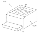
- FIG. 1 is a perspective view illustrating an example of a printing device 1 according to one or more embodiments.
- the printing device 1 illustrated in FIG. 1 may comprise a paper feeding section 10, a printing unit 20, a paper discharging section 30, and a power supply 70.
- FIG. 2 is a block diagram illustrating an example of a functional configuration of the printing unit 20.
- FIG. 2 illustrates an example of a configuration of the printing unit 20 included in the printing device 1.
- the printing unit 20 may comprise a toner 92 and may form any image using the toner 92 on a printing medium 91 such as a paper that is fed from the paper feeding section 10 and sent to the paper discharging section 30.
- the printing unit 20 may comprise an image forming unit 40, a fuser 50, and a controller 60.
- the printing unit 20 may operate by electric power supplied from the power supply 70.
- the power supply 70 may be, for example, a switching power supply device that converts alternating current voltage supplied from a commercial power supply to direct current voltage used in the operation of the printing unit 20.
- the image forming unit 40 may comprise a photosensitive drum 41 and a transfer roller 42.
- the toner 92 may be adhered to a latent image formed on the photosensitive drum 41 using a light source (not illustrated) and then the adhered toner 92 may be transferred onto the printing medium 91 by the transfer roller 42.
- the fuser 50 may comprise a heating roller 51 and a pressure roller 52.
- the toner 92 transferred onto the printing medium 91 may be fused to the printing medium 92 by applying heat and pressure.
- the heating roller 51 may comprise a heater 53 and a temperature sensor 54, and the temperature is controlled by the controller 60.
- the heater 53 may comprise a halogen heater
- the temperature sensor 54 may comprise a thermistor.
- the controller 60 may perform a complete processing in the printing device 1 comprising, for example, image processing and communication processing in addition to the control of the printing unit 20 comprising temperature control for the fuser 50.
- the controller 60 may comprise a hardware circuit comprising a processor.
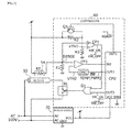
- FIG. 3 is a circuit diagram illustrating an example of the controller 60. In addition to the controller 602, FIG. 3 also shows the power supply 70, heater 53, and temperature sensor 54.
- the controller 60 may comprise, for example, a processor (e.g., CPU), comparators CP1, CP2, digital to analog (DA) converters DAC, resistors R1, R2, and R3, transistor Q1, an OR gate G1, and a relay RL.
- a processor e.g., CPU
- comparators CP1, CP2, digital to analog (DA) converters DAC e.g., DAC
- resistors R1, R2, and R3 e.g., transistors R1, R2, and R3, transistor Q1, an OR gate G1, and a relay RL.
- the controller 60 comprises a sense circuit.
- the sense circuit may comprise the temperature sensor 54 and the resistor R1 connected in series.
- the sense circuit may comprise ends connected to the power supply voltage and the ground voltage and may output, from the connection point between the temperature sensor 54 and the resistance R1, a temperature signal SENSE having a voltage value indicating the temperature of the fuser 50.
- the sense circuit may output a temperature signal SENSE having a voltage value indicating the temperature of the heating roller 51.
- the controller 60 may further comprise a threshold voltage generating circuit.
- the threshold voltage generating circuit may comprise the resistors R2 and R3 be connected in series.
- the threshold voltage generating circuit may comprise ends connected to the power supply voltage and the ground voltage and may output, from the connection point of the resistors R2 and R3, a threshold voltage VTH1.
- the threshold voltage VTH1 may correspond to a target temperature for the warm up of the fuser 50.
- the comparator CP1 may compare the temperature signal SENSE and the threshold voltage VTH1 in an analog value and output a first energization control signal maintaining the temperature of the fuser 50 at the target temperature.
- the comparator CP1 may be a circuit configured to compare two input voltages without intervention by the processor, and may comprise, for example, an analog circuit such as an operational amplifier or the like.
- the first energization control signal may instruct power distribution (HW_ON) at an H level and instruct power disconnection (HW_OFF) at an L level.
- the processor may output a startup notification signal READY and also output a reference signal TMEP and a second energization control signal to control a temperature of the fuser 50 by executing a predetermined program.
- the second energization control signal may instruct power distribution (SW_ON) at an H level and instruct power disconnection (SW_OFF) at an L level.
- the program may perform a number of further processing steps in the printing device 1 comprising, among others, the temperature control of the fuser 50.
- the processor may launch the program in RAM (not illustrated) and then may execute the program launched in RAM by executing a loader program stored in ROM (not illustrated).
- the processor may not output the startup notification signal READY until the temperature control is started by the program, and may output the second energization signal in the L level that instructs the power disconnection (SW_OFF).
- the processor may output the startup notification signal READY in the L level that indicates the temperature control is started, and also output a reference temperature signal TEMP where a reference temperature is expressed with pulse width modulation (PWM).
- the DA converter DAC may convert the reference temperature signal TEMP to a threshold voltage VTH2 that corresponds to the reference temperature.
- the DA convertor DAC may comprise, for example, a simple low-pass filter.
- the comparator CP2 may compare the temperature signal SENSE and the threshold voltage VTH2 in an analog value and then supply the comparison result signal indicating the result of the comparison to the processor.
- the processor may read the temperature of the fuser 50 from the comparison result signal by sweeping the reference temperature expressed by the reference temperature signal TEMP within a predetermined range. Thereby, the processor may output the second energization control signal that instructs for power distribution (SW_ON) and power disconnection (SW_OFF) based on not only a simple temperature control logic by the threshold comparison, but also based on a more advanced temperature control logic such as hysteresis control or predictive control.
- the temperature signal SENSE may be converted to a digital value by the ADC.
- the DA converter DAC and the comparator CP2 may be omitted.
- the energization control circuit may comprise the OR gate G1, relay RL, and transistor Q1.
- the OR gate G1 may supply to the relay RL an OR signal that indicates whether or not the power distribution (HW_ON, SW_ON) is instructed by at least one of the first energization control signal and the second energization control signal.
- the relay RL may perform power distribution and power disconnection to the heater 53 according to the OR signal supplied from the OR gate G1.
- the relay RL may be, for example, an electronic relay comprising a triac, photo-coupler, or the like.
- the transistor Q1 may conduct, or turn on, according to the startup notification signal READY, and connect an endpoint connected to the power supply voltage of the threshold voltage generating circuit comprising the resistors R2 and R3, and the connection points with the resistors R2 and R3.
- the first energization control signal becomes the L level to instruct the power disconnection (HW_OFF) at all times due to shifting of the threshold value voltage VTH1.
- the transistor Q1 is an example of a disabling circuit configured to disable the first energization control signal according to the start notification signal READY.
- the energization control circuit with such configuration may perform the power distribution and power disconnection to the heater 53 according to the first energization control signal until the temperature control is started by the program, and perform the power distribution and power disconnection to the heater 53 according to the second energization control signal after the temperature control is started by the program.
- FIG. 4 is a flow chart representing an example of the operation of the printing device 1, illustrating the operation carried out in the controller 60 when the power supply is initiated at the time of startup. Such operation may be performed, for example, when the power activation is operated by user while the power supply of the printing device 1 is turned off, or when a printing instruction is given from an information equipment while the printing device in a deep sleep mode state in which the supply of the main power is stopped.
- the flowchart illustrated in FIG. 4 shows different operations performed by the controller 60: an operation performed by the processor, i.e., by a software function, and an operation performed by the control circuit, i.e., by the hardware function, that is the hardware other than the processor.
- the processor may load a program (S101).
- the program loading may comprise, for example, a program deployment process from ROM to RAM by the loader program.
- the processor may first perform an initialization process (S102) when the operation is started according to the loaded program, and the temperature control may be started (S103) by the program thereafter.
- the controller may perform the temperature control (S201) by the hardware function.
- the first energization control signal that instructs the power distribution (HW_ON) or the power disconnection (HW_OFF) may be generated according to whether the temperature of the fuser 50 reaches the target temperature by comparing the temperature signal SENSE and the threshold voltage VTH1 with the comparator CP1.
- the first energization control signal may be transferred to the relay RL via the OR gate G1, and the power distribution and the power disconnection to the heater 53 may be carried out according to the first energization control signal by the relay RL.
- the processor may output the startup notification signal READY when the temperature control is started (S104).
- the transistor Q1 may be turned on according to the startup notification signal READY to shift the threshold voltage VTH1. Accordingly, the first energization control signal may be fused in the L-level to instruct the power disconnection (HW_OFF) and be disabled (S202).
- the processor may output a reference temperature signal TEMP (S105), acquire a comparison result signal from the comparison result signal from the comparator CP2, and identify the necessity of power distribution to the heater 53 from the acquired comparison result signal (S106).
- TEMP reference temperature signal
- S106 The details of the process for identifying the necessity of the power distribution have mere illustrative purposes and are not limiting; the necessity of the power distribution may be identified, for example, by a simple temperature control logic by comparing threshold values, or it may be identified based on a more advanced temperature control logic such as a hysteresis or predictive control.
- the processor may output a second energization control signal (S107 to S109) that instructs one of the power distribution (SW_ON) or the power disconnection (SW_OFF) corresponding to the necessity of the identified power distribution.
- the second energization signal may be transferred to the relay RL via the OR gate G1, and the power distribution or power disconnection may be performed (S203) to the heater 53 according to the second energization control signal by the relay RL.
- the temperature control by the hardware function can be performed in the control circuit in parallel with all the processing outperformed until the temperature control is started by the software function.
- a printing device may comprise only one processor and a process, which may require considerable time such as loading a program, must be outperformed by the processor when the power supply is initiated. Even in such a case, the controller 60 may start heating of the fuser at the same time when the power supply is initiated by performing the temperature control by the hardware function in the control circuit in parallel with the processing, so that the time required for the first print can be reduced.
- the exemplary configuration of the controller 60 provided above may be used also, for example, when the printing device comprises two or more processors.
- heating of the fuser may be started by performing the temperature control by the hardware function in the control circuit.
- the processing requiring a considerable time such as loading a program, may be performed in parallel and distributed to the two or more processors, so that the time required for the first print can be reduced.
- printing devices comprising a fuser that requires temperature control may comprise, for example, laser printers, LED printers, or the like.
Landscapes
- Physics & Mathematics (AREA)
- General Physics & Mathematics (AREA)
- Control Or Security For Electrophotography (AREA)
- Fixing For Electrophotography (AREA)
Abstract
A printing device comprising a heater (53) configured to heat a fuser to fuse toner on a printing medium, a sense circuit (54, R1) configured to generate a temperature signal (SENSE) indicating a voltage value corresponding to a temperature of the fuser, a comparator configured to compare the voltage value indicated by the temperature signal (SENSE) with a threshold voltage value corresponding to a target temperature for the fuser and to output a first signal maintaining the temperature of the fuser at the target temperature, a processor (CPU) configured to execute a program after a power supply for the printing device is initiated and to output a second signal controlling the temperature of the fuser, and an energization control circuit (G1, RL, Q1) configured to, before the processor (CPU) starts execution of the program, control power distribution to the heater (53) according to the first signal, and, after the processor (CPU) has started the execution, to control the power distribution to the heater (53) according to the second signal.
Description
- The present invention relates generally to a printing device and to a printing method.
- Various techniques have been studied to reduce the time required to begin printing immediately after power of a printing device is turned on or for printing immediately after the printing device is restored from a deep sleep mode where supply of the main power is turned off. These printings are called a first print, and a majority of time required for the first print is occupied by a warm-up time to heat a fuser by a heater.
- For example, Japanese Unexamined Patent Application Publication No.
2011-227360 - According to Japanese Unexamined Patent Application Publication No.
2011-227360 - However, this conventional technique requires at least two processors and cannot be applied to a printing device comprising only one processor.
- In one aspect, embodiments of the invention relate to a printing device having a configuration capable of reducing the time required for first print, both in the presence of one processor only and in the presence of two or more processors.
- A printing device according to one aspect of the present invention may comprise a heater configured to heat a fuser to fuse toner on a printing medium; a sense circuit configured to generate a temperature signal indicating a voltage value corresponding to a temperature of the fuser; a comparator configured to compare the voltage value indicated by the temperature signal with a threshold voltage value corresponding to a target temperature for the fuser and to output a first energization control signal maintaining the temperature of the fuser at the target temperature; a processor configured to execute a program after a power supply for the printing device is initiated and to output a second energization control signal controlling the temperature of the fuser; and an energization control circuit configured to control power distribution to the heater according to the first energization control signal before the processor starts execution of the program, and to control the power distribution to the heater according to the second energization control signal after the processor has started execution of the program.
- According to one or more embodiments based on this configuration, the program may perform temperature control according to a software function in the processor. In parallel with all processing performed prior to starting the temperature control by the program, comprising, for example, image processing and communication processing, temperature control can be performed by a hardware circuit. Accordingly, the heating of the fuser may be started at the same time when the power supply is turned on, so that the time required for the first print can be reduced.
- According to one or more embodiments, the printing device may further comprise the fuser to fuse toner on the printing medium.
- According to one or more embodiments, the processor may, by executing the program, be further configured to output a startup notification signal, and the energization control circuit may comprise a disabling circuit configured to disable the first energization control signal according to the startup notification signal.
- According to one or more embodiments based on this configuration, more advanced temperature control may be performed using a software function, because temperature control by a hardware circuit is disabled after temperature control using a software function is started.
- According to one or more embodiments, the printing device may further comprise a threshold voltage generating circuit configured to output a threshold voltage value. According to one or more embodiments, the threshold voltage generating circuit may comprise a plurality of resistors connected in series and may be configured to output the threshold voltage value from a connection point of the resistors by applying a predetermined voltage to both ends of the resistors. According to one or more embodiments, the disabling circuit may comprise a transistor connecting the connection point and one of the end points of the threshold voltage generating circuit according to the startup notification signal.
- According to one or more embodiments based on this configuration, the first energization control signal can be disabled by shifting the threshold voltage.
- According to another aspect of the present invention, a printing method is provided, the method comprising the steps of: generating a temperature signal indicating a voltage value corresponding to a temperature of a fuser of toner of a printing device; comparing the voltage value indicated by the temperature signal with a threshold voltage value corresponding to a target temperature for the fuser; outputting a first energization control signal maintaining the temperature of the fuser at the target temperature; controlling power distribution to a heater of the printing device according to the first energization control signal; executing a program after a power supply for the printing device is initiated and outputting a second energization control signal controlling the temperature of the fuser; and controlling, before execution of the program is started, power distribution to the heater according to the first energization control signal, and controlling, after execution of the program is started, the power distribution to the heater according to the second energization control signal. The program may be executed by a processor.
- One or more of these steps of the method may be performed by a system, a method, an integrated circuit, a computer program, or a recording medium such as a computer readable CD-ROM or the like, and may also be performed by various combinations of a system, method, integrated circuit, computer program or recording medium.
- With the printing device and method according to one of the embodiments of the present invention, all processing performed prior to starting temperature control by the software function can be performed in parallel to the temperature control. For example, the processing may be performed by a processor, while the temperature control may be performed by a hardware circuit.
- With a conventional printing device comprising only a single processor, a process requiring considerable time, such as loading a program, must be performed by the single processor when the power supply is initiated. However, according to one or more embodiments of the invention, even when the printing device comprises only one processor, heating of the fuser may begin at the same time as when the power supply is turned on by performing a temperature control by a hardware function using a control circuit in parallel with processing, so that the time required for the first print can be reduced.
- According to one or more embodiments, the printing device may comprise two or more processors. Also in this case, the configuration of one or more embodiments as defined above may be applied to, for example, the processor for performing temperature control. Accordingly, at the same time that the power supply is initiated, heating of the fuser may be started by performing temperature control by the hardware function in the control circuit, and processes requiring a considerable time, such as loading a program, may be performed in parallel and distributed in two or more processors so that the time required for fast printing can be reduced.
-
-
FIG. 1 is a perspective view illustrating an example of an external appearance of a printing device according to one or more embodiments of the present invention. -
FIG. 2 is a block diagram illustrating an example of a functional configuration of the printing device according to one or more embodiments of the present invention. -
FIG. 3 is a circuit diagram illustrating an example of a controller of the printing device according to one or more embodiments of the present invention. -
FIG. 4 is a flowchart illustrating an example of operation of the printing device according to one or more embodiments of the present invention. - Embodiments of the present invention are described in detail hereinafter with reference to the drawings. Each embodiment described below illustrates an example of the present invention and is provided for mere illustrative purposes. However, these embodiments can be combined with each other and are not intended to be limited to the specific combinations of features disclosed herein. Also, numerical values, shapes, materials, compositional elements, disposed positions and connection modes of the compositional elements, steps and order of steps are illustrated as an example and these are not intended to limit the present invention.
- A printing device according to one or more embodiments is a printing device having a configuration suitable for reducing the time required for a first print.
- The printing device may be, for example, an electrophotographic printing device or any other type of printing device comprising a heater configured to heat a fuser to fuse toner on a printing medium. The printing device may comprise a fuser requiring temperature control. Although in the following an exemplary printing device is described comprising such a fuser, the fuser, according to one or more embodiments, may be part of a unit separate from the printing device.
-
FIG. 1 is a perspective view illustrating an example of aprinting device 1 according to one or more embodiments. Theprinting device 1 illustrated inFIG. 1 may comprise apaper feeding section 10, aprinting unit 20, apaper discharging section 30, and apower supply 70. -
FIG. 2 is a block diagram illustrating an example of a functional configuration of theprinting unit 20.FIG. 2 illustrates an example of a configuration of theprinting unit 20 included in theprinting device 1. - The
printing unit 20 may comprise atoner 92 and may form any image using thetoner 92 on aprinting medium 91 such as a paper that is fed from thepaper feeding section 10 and sent to thepaper discharging section 30. Theprinting unit 20 may comprise animage forming unit 40, afuser 50, and acontroller 60. Theprinting unit 20 may operate by electric power supplied from thepower supply 70. - The
power supply 70 may be, for example, a switching power supply device that converts alternating current voltage supplied from a commercial power supply to direct current voltage used in the operation of theprinting unit 20. - The
image forming unit 40 may comprise aphotosensitive drum 41 and atransfer roller 42. Thetoner 92 may be adhered to a latent image formed on thephotosensitive drum 41 using a light source (not illustrated) and then the adheredtoner 92 may be transferred onto theprinting medium 91 by thetransfer roller 42. - The
fuser 50 may comprise aheating roller 51 and apressure roller 52. Thetoner 92 transferred onto theprinting medium 91 may be fused to theprinting medium 92 by applying heat and pressure. Theheating roller 51 may comprise aheater 53 and atemperature sensor 54, and the temperature is controlled by thecontroller 60. For example, theheater 53 may comprise a halogen heater, and thetemperature sensor 54 may comprise a thermistor. - The
controller 60 may perform a complete processing in theprinting device 1 comprising, for example, image processing and communication processing in addition to the control of theprinting unit 20 comprising temperature control for thefuser 50. According to one or more embodiments, thecontroller 60 may comprise a hardware circuit comprising a processor. -
FIG. 3 is a circuit diagram illustrating an example of thecontroller 60. In addition to the controller 602,FIG. 3 also shows thepower supply 70,heater 53, andtemperature sensor 54. - As illustrated in
FIG. 3 , thecontroller 60 may comprise, for example, a processor (e.g., CPU), comparators CP1, CP2, digital to analog (DA) converters DAC, resistors R1, R2, and R3, transistor Q1, an OR gate G1, and a relay RL. - According to one or more embodiments, the
controller 60 comprises a sense circuit. According to one or more embodiments, as shown inFIG. 3 , the sense circuit may comprise thetemperature sensor 54 and the resistor R1 connected in series. The sense circuit may comprise ends connected to the power supply voltage and the ground voltage and may output, from the connection point between thetemperature sensor 54 and the resistance R1, a temperature signal SENSE having a voltage value indicating the temperature of thefuser 50. With reference to the example of fuser shown inFIG. 2 , the sense circuit may output a temperature signal SENSE having a voltage value indicating the temperature of theheating roller 51. - According to one or more embodiments, the
controller 60 may further comprise a threshold voltage generating circuit. According to one or more embodiments, as shown inFIG. 3 , the threshold voltage generating circuit may comprise the resistors R2 and R3 be connected in series. The threshold voltage generating circuit may comprise ends connected to the power supply voltage and the ground voltage and may output, from the connection point of the resistors R2 and R3, a threshold voltage VTH1. The threshold voltage VTH1 may correspond to a target temperature for the warm up of thefuser 50. - The comparator CP1 may compare the temperature signal SENSE and the threshold voltage VTH1 in an analog value and output a first energization control signal maintaining the temperature of the
fuser 50 at the target temperature. The comparator CP1 may be a circuit configured to compare two input voltages without intervention by the processor, and may comprise, for example, an analog circuit such as an operational amplifier or the like. As an example, the first energization control signal may instruct power distribution (HW_ON) at an H level and instruct power disconnection (HW_OFF) at an L level. - The processor may output a startup notification signal READY and also output a reference signal TMEP and a second energization control signal to control a temperature of the
fuser 50 by executing a predetermined program. As an example, the second energization control signal may instruct power distribution (SW_ON) at an H level and instruct power disconnection (SW_OFF) at an L level. - Here, as an example, reference will be made to a situation that requires considerable time to start the program in the processor. For example, the program may perform a number of further processing steps in the
printing device 1 comprising, among others, the temperature control of thefuser 50. As described in the background section, the processor may launch the program in RAM (not illustrated) and then may execute the program launched in RAM by executing a loader program stored in ROM (not illustrated). - The processor may not output the startup notification signal READY until the temperature control is started by the program, and may output the second energization signal in the L level that instructs the power disconnection (SW_OFF).
- After the temperature control is started by the program, the processor may output the startup notification signal READY in the L level that indicates the temperature control is started, and also output a reference temperature signal TEMP where a reference temperature is expressed with pulse width modulation (PWM). The DA converter DAC may convert the reference temperature signal TEMP to a threshold voltage VTH2 that corresponds to the reference temperature. The DA convertor DAC may comprise, for example, a simple low-pass filter. The comparator CP2 may compare the temperature signal SENSE and the threshold voltage VTH2 in an analog value and then supply the comparison result signal indicating the result of the comparison to the processor.
- The processor may read the temperature of the fuser 50 from the comparison result signal by sweeping the reference temperature expressed by the reference temperature signal TEMP within a predetermined range. Thereby, the processor may output the second energization control signal that instructs for power distribution (SW_ON) and power disconnection (SW_OFF) based on not only a simple temperature control logic by the threshold comparison, but also based on a more advanced temperature control logic such as hysteresis control or predictive control.
- When the processor has a built-in analog to digital converter (ADC) that can convert a voltage acquired from the outside, the temperature signal SENSE may be converted to a digital value by the ADC. In this case, the DA converter DAC and the comparator CP2 may be omitted.
- According to one or more embodiments, the energization control circuit may comprise the OR gate G1, relay RL, and transistor Q1.
- The OR gate G1 may supply to the relay RL an OR signal that indicates whether or not the power distribution (HW_ON, SW_ON) is instructed by at least one of the first energization control signal and the second energization control signal.
- The relay RL may perform power distribution and power disconnection to the
heater 53 according to the OR signal supplied from the OR gate G1. The relay RL may be, for example, an electronic relay comprising a triac, photo-coupler, or the like. - The transistor Q1 may conduct, or turn on, according to the startup notification signal READY, and connect an endpoint connected to the power supply voltage of the threshold voltage generating circuit comprising the resistors R2 and R3, and the connection points with the resistors R2 and R3. When the transistor Q1 is conducted, the first energization control signal becomes the L level to instruct the power disconnection (HW_OFF) at all times due to shifting of the threshold value voltage VTH1. The transistor Q1 is an example of a disabling circuit configured to disable the first energization control signal according to the start notification signal READY.
- The energization control circuit with such configuration may perform the power distribution and power disconnection to the
heater 53 according to the first energization control signal until the temperature control is started by the program, and perform the power distribution and power disconnection to theheater 53 according to the second energization control signal after the temperature control is started by the program. - An exemplary operation of the
printing device 1 configured as described above will be described here below. -
FIG. 4 is a flow chart representing an example of the operation of theprinting device 1, illustrating the operation carried out in thecontroller 60 when the power supply is initiated at the time of startup. Such operation may be performed, for example, when the power activation is operated by user while the power supply of theprinting device 1 is turned off, or when a printing instruction is given from an information equipment while the printing device in a deep sleep mode state in which the supply of the main power is stopped. - The flowchart illustrated in
FIG. 4 shows different operations performed by the controller 60: an operation performed by the processor, i.e., by a software function, and an operation performed by the control circuit, i.e., by the hardware function, that is the hardware other than the processor. - The processor may load a program (S101). The program loading may comprise, for example, a program deployment process from ROM to RAM by the loader program. The processor may first perform an initialization process (S102) when the operation is started according to the loaded program, and the temperature control may be started (S103) by the program thereafter.
- In parallel with the operations in steps S101 to S103 that are performed in the processor, the controller may perform the temperature control (S201) by the hardware function. For example, the first energization control signal that instructs the power distribution (HW_ON) or the power disconnection (HW_OFF) may be generated according to whether the temperature of the
fuser 50 reaches the target temperature by comparing the temperature signal SENSE and the threshold voltage VTH1 with the comparator CP1. The first energization control signal may be transferred to the relay RL via the OR gate G1, and the power distribution and the power disconnection to theheater 53 may be carried out according to the first energization control signal by the relay RL. - The processor may output the startup notification signal READY when the temperature control is started (S104). The transistor Q1 may be turned on according to the startup notification signal READY to shift the threshold voltage VTH1. Accordingly, the first energization control signal may be fused in the L-level to instruct the power disconnection (HW_OFF) and be disabled (S202).
- The processor may output a reference temperature signal TEMP (S105), acquire a comparison result signal from the comparison result signal from the comparator CP2, and identify the necessity of power distribution to the
heater 53 from the acquired comparison result signal (S106). The details of the process for identifying the necessity of the power distribution have mere illustrative purposes and are not limiting; the necessity of the power distribution may be identified, for example, by a simple temperature control logic by comparing threshold values, or it may be identified based on a more advanced temperature control logic such as a hysteresis or predictive control. - The processor may output a second energization control signal (S107 to S109) that instructs one of the power distribution (SW_ON) or the power disconnection (SW_OFF) corresponding to the necessity of the identified power distribution.
- The second energization signal may be transferred to the relay RL via the OR gate G1, and the power distribution or power disconnection may be performed (S203) to the
heater 53 according to the second energization control signal by the relay RL. - According to one or more embodiments of the
controller 60, as evident from the embodiments described above, the temperature control by the hardware function can be performed in the control circuit in parallel with all the processing outperformed until the temperature control is started by the software function. - For example, a printing device may comprise only one processor and a process, which may require considerable time such as loading a program, must be outperformed by the processor when the power supply is initiated. Even in such a case, the
controller 60 may start heating of the fuser at the same time when the power supply is initiated by performing the temperature control by the hardware function in the control circuit in parallel with the processing, so that the time required for the first print can be reduced. - However, the exemplary configuration of the
controller 60 provided above may be used also, for example, when the printing device comprises two or more processors. In such a case, for example, at the same time the power supply is initiated, heating of the fuser may be started by performing the temperature control by the hardware function in the control circuit. At the same time, the processing requiring a considerable time, such as loading a program, may be performed in parallel and distributed to the two or more processors, so that the time required for the first print can be reduced. - Descriptions of the printing device according to one or a plurality of modes of the present invention were given above based on a number of embodiments; however, the present invention is not limited to the described embodiments. Various modifications are possible by combining one or more embodiments together, or by combining the features of one or more embodiments together.
- According to one or more embodiments, printing devices comprising a fuser that requires temperature control may comprise, for example, laser printers, LED printers, or the like.
- Although the disclosure has been described with respect to only a limited number of embodiments, those skilled in the art, having benefit of this disclosure, will appreciate that various other embodiments may be devised without departing from the scope of the present invention. Accordingly, the scope of the invention should be limited only by the attached claims.
-
- 1
- printing device
- 10
- paper feeding section
- 20
- printing unit
- 30
- paper discharging section
- 40
- image forming unit
- 41
- photosensitive drum
- 42
- transfer roller
- 50
- fuser
- 51
- heating roller
- 52
- pressure roller
- 53
- heater
- 54
- temperature sensor
- 60
- controller
- 70
- power supply
- 91
- printing medium
- 92
- toner
- CP1, CP2
- comparator
- CPU
- processor
- DAC
- DA convertor
- G1
- OR gate
-
Q 1 - transistor
- R1, R2, R3
- resistor
- RL
- relay
Claims (8)
- A printing device (1) comprising:a heater (53) configured to heat a fuser(50) to fuse toner (92) on a printing medium (91);a sense circuit (54, R1) configured to generate a temperature signal (SENSE) indicating a voltage value corresponding to a temperature of the fuser (50);a comparator (CP1) configured to compare the voltage value indicated by the temperature signal (SENSE) with a threshold voltage value (VTH1) corresponding to a target temperature for the fuser (50) and to output a first energization control signal maintaining the temperature of the fuser (50) at the target temperature;a processor (CPU) configured to execute a program after a power supply for the printing device (1) is initiated and to output a second energization control signal controlling the temperature of the fuser (50); andan energization control circuit (G1, RL, Q1) configured to, before the processor (CPU) starts execution of the program, control power distribution to the heater (53) according to the first energization control signal, and, after the processor (CPU) has started execution of the program, to control the power distribution to the heater (53) according to the second energization control signal.
- The printing device (1) according to claim 1, wherein
the processor (CPU), by executing the program, is further configured to output a startup notification signal (READY), and
the energization control circuit (G1, RL, Q1) comprises a disabling circuit (Q1) configured to disable the first energization control signal according to the startup notification signal (READY). - The printing device (1) according to claim 1 or claim 2, further comprising a threshold voltage generating circuit configured to output the threshold voltage value (VTH1).
- The printing device (1) according to claim 3, wherein the threshold voltage generating circuit comprises a plurality of resistors (R2, R3) connected in series and is configured to output the threshold voltage value (VTH1) from a connection point of the resistors (R2, R3) by applying a predetermined voltage to both ends of the resistors (R2, R3).
- The printing device (1) according to claim 2, further comprising:a threshold voltage generating circuit comprising a plurality of resistors (R2, R3) connected in series and being configured to output the threshold voltage value (VTH1) from a connection point of the resistors (R2, R3) by applying a predetermined voltage to both ends of the resistors (R2, R3), andthe disabling circuit (Q1) comprises a transistor (Q1) connecting the connection point and one of the end points of the threshold voltage generating circuit according to the startup notification signal (READY).
- Aprinting method, comprising:generating a temperature signal (SENSE) indicating a voltage value corresponding to a temperature of a fuser (50) of toner (92) of a printing device (1);comparing the voltage value indicated by the temperature signal (SENSE) with a threshold voltage value (VTH1) corresponding to a target temperature for the fuser (50);outputting a first energization control signal maintaining the temperature of the fuser (50) at the target temperature;controlling power distribution to a heater (53) of the printing device (1) according to the first energization control signal;executing a program after a power supply for the printing device (1) is initiated and outputting a second energization control signal controlling the temperature of the fuser (50); andcontrolling, before execution of the program is started, power distribution to the heater (53) according to the first energization control signal, and controlling, after execution of the program is started, the power distribution to the heater (53) according to the second energization control signal.
- The method according to claim 6, further comprising:outputting a startup notification signal (READY); anddisabling the first energization control signal according to the startup notification signal (READY).
- The method according to claim 7, wherein the printing device (1) comprises a threshold voltage generating circuit comprising a plurality of resistors (R2, R3) connected in series, the method further comprising:outputting the threshold voltage value (VTH1) from a connection point of the resistors (R2, R3) of the threshold voltage generating circuit by applying a predetermined voltage to both ends of the resistors (R2, R3); andconnecting the connection point and one of the end points of the threshold voltage generating circuit according to the startup notification signal (READY).
Applications Claiming Priority (1)
| Application Number | Priority Date | Filing Date | Title |
|---|---|---|---|
| JP2013258880A JP2015114638A (en) | 2013-12-16 | 2013-12-16 | Printer |
Publications (1)
| Publication Number | Publication Date |
|---|---|
| EP2887147A1 true EP2887147A1 (en) | 2015-06-24 |
Family
ID=52006805
Family Applications (1)
| Application Number | Title | Priority Date | Filing Date |
|---|---|---|---|
| EP14193169.1A Withdrawn EP2887147A1 (en) | 2013-12-16 | 2014-11-14 | Printing device and method |
Country Status (3)
| Country | Link |
|---|---|
| US (1) | US20150168885A1 (en) |
| EP (1) | EP2887147A1 (en) |
| JP (1) | JP2015114638A (en) |
Citations (3)
| Publication number | Priority date | Publication date | Assignee | Title |
|---|---|---|---|---|
| US20060029445A1 (en) * | 2004-08-05 | 2006-02-09 | Konica Minolta Business Technologies, Inc. | Bookbinding system and image forming system |
| JP2011227360A (en) | 2010-04-22 | 2011-11-10 | Oki Data Corp | Image forming apparatus |
| US20130251390A1 (en) * | 2012-03-22 | 2013-09-26 | Kenji Ishii | Fixing device, image forming apparatus incorporating same, and fixing method |
Family Cites Families (3)
| Publication number | Priority date | Publication date | Assignee | Title |
|---|---|---|---|---|
| JP4177138B2 (en) * | 2003-02-28 | 2008-11-05 | 株式会社リコー | Heater control device and image forming apparatus |
| JP4133588B2 (en) * | 2003-05-26 | 2008-08-13 | 京セラミタ株式会社 | Fixing device, image forming device, heater temperature control program |
| JP4379815B2 (en) * | 2006-11-08 | 2009-12-09 | 村田機械株式会社 | Image forming apparatus and initialization program for image forming apparatus |
-
2013
- 2013-12-16 JP JP2013258880A patent/JP2015114638A/en active Pending
-
2014
- 2014-11-14 EP EP14193169.1A patent/EP2887147A1/en not_active Withdrawn
- 2014-11-18 US US14/546,122 patent/US20150168885A1/en not_active Abandoned
Patent Citations (3)
| Publication number | Priority date | Publication date | Assignee | Title |
|---|---|---|---|---|
| US20060029445A1 (en) * | 2004-08-05 | 2006-02-09 | Konica Minolta Business Technologies, Inc. | Bookbinding system and image forming system |
| JP2011227360A (en) | 2010-04-22 | 2011-11-10 | Oki Data Corp | Image forming apparatus |
| US20130251390A1 (en) * | 2012-03-22 | 2013-09-26 | Kenji Ishii | Fixing device, image forming apparatus incorporating same, and fixing method |
Also Published As
| Publication number | Publication date |
|---|---|
| US20150168885A1 (en) | 2015-06-18 |
| JP2015114638A (en) | 2015-06-22 |
Similar Documents
| Publication | Publication Date | Title |
|---|---|---|
| US8818229B2 (en) | Current-supply control unit, fusing device, image forming apparatus, and current-supply control method | |
| JP2012128107A (en) | Image forming apparatus and fixing control method | |
| JP2017053915A (en) | Image forming apparatus | |
| JP5971214B2 (en) | Data processing apparatus and data processing program | |
| JP6842354B2 (en) | Image forming device | |
| US20150168885A1 (en) | Printing device | |
| KR100739796B1 (en) | Power control method and apparatus for heating roller | |
| JP2017026741A (en) | Image forming apparatus, control method, and control program | |
| JP4815384B2 (en) | Image forming system | |
| JP2020118772A (en) | Image forming apparatus, image forming method, and program | |
| JP6414011B2 (en) | Power supply device and image forming apparatus provided with the same | |
| US9921529B2 (en) | Method of controlling fuser with fuser controller and main controller and image forming apparatus including the fuser controller and the main controller | |
| US20080181640A1 (en) | Image forming apparatus and control method thereof | |
| KR100754206B1 (en) | Power control method and apparatus for heating roller | |
| KR100677631B1 (en) | Power control method and apparatus for fixing heating roller | |
| JPH1173057A (en) | Image forming apparatus, image forming method, and storage medium storing image forming procedure | |
| JP5980058B2 (en) | Image forming apparatus | |
| KR100788679B1 (en) | Power control method and apparatus for fixing heating roller | |
| JP2008145450A (en) | Image forming apparatus, power control method for the apparatus, program, and storage medium | |
| US8266455B2 (en) | Apparatus and method for controlling power of fixing unit | |
| JP2015036695A (en) | Image forming apparatus, control method, and computer program | |
| JP2011227360A (en) | Image forming apparatus | |
| JP2012247872A (en) | Electronic apparatus, control method thereof, and program | |
| JP2017122814A (en) | Image forming apparatus | |
| KR101329735B1 (en) | Method and apparatus for controlling power for Instant Heating Roller |
Legal Events
| Date | Code | Title | Description |
|---|---|---|---|
| PUAI | Public reference made under article 153(3) epc to a published international application that has entered the european phase |
Free format text: ORIGINAL CODE: 0009012 |
|
| 17P | Request for examination filed |
Effective date: 20141114 |
|
| AK | Designated contracting states |
Kind code of ref document: A1 Designated state(s): AL AT BE BG CH CY CZ DE DK EE ES FI FR GB GR HR HU IE IS IT LI LT LU LV MC MK MT NL NO PL PT RO RS SE SI SK SM TR |
|
| AX | Request for extension of the european patent |
Extension state: BA ME |
|
| STAA | Information on the status of an ep patent application or granted ep patent |
Free format text: STATUS: THE APPLICATION IS DEEMED TO BE WITHDRAWN |
|
| 18D | Application deemed to be withdrawn |
Effective date: 20160105 |