EP2886980B1 - Aufgereihte kühlvorrichtungen - Google Patents
Aufgereihte kühlvorrichtungen Download PDFInfo
- Publication number
- EP2886980B1 EP2886980B1 EP13829429.3A EP13829429A EP2886980B1 EP 2886980 B1 EP2886980 B1 EP 2886980B1 EP 13829429 A EP13829429 A EP 13829429A EP 2886980 B1 EP2886980 B1 EP 2886980B1
- Authority
- EP
- European Patent Office
- Prior art keywords
- door
- door body
- shaft
- pedal member
- pedal
- Prior art date
- Legal status (The legal status is an assumption and is not a legal conclusion. Google has not performed a legal analysis and makes no representation as to the accuracy of the status listed.)
- Not-in-force
Links
Images





Classifications
-
- E—FIXED CONSTRUCTIONS
- E05—LOCKS; KEYS; WINDOW OR DOOR FITTINGS; SAFES
- E05B—LOCKS; ACCESSORIES THEREFOR; HANDCUFFS
- E05B17/00—Accessories in connection with locks
- E05B17/0025—Devices for forcing the wing firmly against its seat or to initiate the opening of the wing
- E05B17/0033—Devices for forcing the wing firmly against its seat or to initiate the opening of the wing for opening only
-
- E—FIXED CONSTRUCTIONS
- E05—LOCKS; KEYS; WINDOW OR DOOR FITTINGS; SAFES
- E05B—LOCKS; ACCESSORIES THEREFOR; HANDCUFFS
- E05B53/00—Operation or control of locks by mechanical transmissions, e.g. from a distance
- E05B53/001—Foot-operation
-
- F—MECHANICAL ENGINEERING; LIGHTING; HEATING; WEAPONS; BLASTING
- F25—REFRIGERATION OR COOLING; COMBINED HEATING AND REFRIGERATION SYSTEMS; HEAT PUMP SYSTEMS; MANUFACTURE OR STORAGE OF ICE; LIQUEFACTION SOLIDIFICATION OF GASES
- F25D—REFRIGERATORS; COLD ROOMS; ICE-BOXES; COOLING OR FREEZING APPARATUS NOT OTHERWISE PROVIDED FOR
- F25D23/00—General constructional features
- F25D23/02—Doors; Covers
-
- F—MECHANICAL ENGINEERING; LIGHTING; HEATING; WEAPONS; BLASTING
- F25—REFRIGERATION OR COOLING; COMBINED HEATING AND REFRIGERATION SYSTEMS; HEAT PUMP SYSTEMS; MANUFACTURE OR STORAGE OF ICE; LIQUEFACTION SOLIDIFICATION OF GASES
- F25D—REFRIGERATORS; COLD ROOMS; ICE-BOXES; COOLING OR FREEZING APPARATUS NOT OTHERWISE PROVIDED FOR
- F25D2400/00—General features of, or devices for refrigerators, cold rooms, ice-boxes, or for cooling or freezing apparatus not covered by any other subclass
- F25D2400/06—Refrigerators with a vertical mullion
Definitions
- Embodiments of the present invention generally relate to a household appliance, and more particularly, to a side-by-side refrigerator.
- the refrigerator comprises a refrigerator body, a left door body, a right door body, a support, a left crow bar, a right crow bar, a left pedal and a right pedal, wherein the support is arranged at the lower end of the refrigerator body; the left crow bar and the right crow bar are pivotally installed on the support in a withdrawal position and a push open position respectively; the left door body is opened when the left crow bar is in the push open position and the left door body is allowed to be closed when the left crow bar is in the withdrawal position; the right door body is opened when the right crow bar is in the push open position and the right door body is allowed to be closed when the right crow bar is in the withdrawal position; the left pedal is pivotally installed on the support between an uplift position and a tread-down position so as to drive the right crow bar to rotate between the withdrawal position and the push open position; and the right pedal is pivotally installed on the support so as to drive the
- WO96/36256A1 provides a foot pedal door opener device for a side-by-side cabinet, which includes a right side foot pedal for opening a left side door of the side-by-side cabinet, and a left side foot pedal for opening a right side door of the side-by-side cabinet.
- the right and left side foot pedals are pivotally attached to pivot points on the cabinet.
- Actuator members are fixedly attached to the right and left side foot pedals.
- the actuator members are disposed to engage the opposite doors when a foot pedal is actuated, thereby opening the opposite door.
- the actuator members extend from one foot pedal toward the other foot pedal, such that a portion of the actuator members are in an overlapping, non-interfering relationship.
- KR20090043972A provides a refrigerator, which includes: a main body in which a cool air storage room is built up; a door hinge-coupled in the front side of the main body; and a pedal part combined in the door to be rotatable.
- a pressurization member is mounted on the door inside. The pressurization member giving the power delivered from the pedal part to the main body.
- a housing having the pedal part and the pressurization member is combined with the door.
- CN1548878A relates to kimchi refrigerator, and especially a pickle refrigerator capable of being foot opened.
- the kimchi refrigerator includes pickle refrigerator main body to form the storage space; refrigerator door hinged to the main body to open and close the storage space inside the main body; and pedal part set in the lower part of the refrigerator to open the refrigerator door.
- Embodiments of the present invention seek to solve at least one of the problems existing in the related art to at least some extent, or to provide a consumer with a useful commercial choice. Accordingly, an object of the present invention is to provide a side-by-side refrigerator, of which a door is easy and convenient to open.
- embodiments of the present invention provide a side-by-side refrigerator, including: a refrigerator body; a left door body and a right door body rotatably disposed on the refrigerator body; a left door member disposed on the refrigerator body and movable between a left opening position in which the left door body is opened and a left closing position in which the left door body is allowed to be closed; a right door member disposed on the refrigerator body and movable between a right opening position in which the right door body is opened and a right closing position in which the right door body is allowed to be closed; a left pedal member connected with the right door member, corresponding to the left door body in an up and down direction and movable between a left stepping position and a left lifting position, wherein when the left pedal member moves from the left lifting position to the left stepping position, the right door member is driven to move from the right closing position to the right opening position; and a right pedal member connected with the left door member, corresponding to the right door body in the up and down direction and
- the left door body may be opened by stepping the right pedal member and the right door body may be opened by stepping the left pedal member, so that in processes of opening the left door body and the right door body, the left door body and the right door body will not interfere with feet or legs of the user, and thus it is easier and more convenient for the user to open the left door body and the right door body.
- the door of the side-by-side refrigerator is easy and convenient to be opened.
- the refrigerator further includes a bracket, and the left door member, the right door member, the left pedal member and the right pedal member are disposed on the bracket respectively.
- the bracket is disposed on a front surface of the refrigerator body and is located below the left door body and the right door body.
- the side-by-side refrigerator further includes a first shaft and a second shaft pivotally disposed on the bracket and spaced from each other in the up and down direction, in which the second shaft is connected with the left door member and defines a right end connected with the right pedal member and a left end, the first shaft is connected with the right door member and defines a left end connected with the left pedal member and a right end.
- the bracket pivotally.
- the left door member includes a first left door arm connected with the left end of the second shaft and adjacent to the left edge of the left door body and a second left door arm connected with the second shaft and located between the first left door arm and the right pedal member; in which the right door member comprises a first right door arm connected with the right end of the first shaft and adjacent to the right edge of the right door body and a second right door arm connected with the first shaft and located between the first right door arm and the left pedal member.
- the user By disposing the first left door arm and the second left door arm, the user can open the left door body with a little effort and the left door body can also obtain a larger power-assisted travel.
- the first right door arm and the second right door arm By disposing the first right door arm and the second right door arm, the user can open the right door body with a little effort and the right door body can also obtain a larger power-assisted travel.
- the left door member and the left pedal member are adjacent to a right edge of the left door body, and the right door member and the right pedal member are adjacent to a left edge of the right door body.
- the left door member is away from a left hinge and the right door member is away from a right hinge, such that the left door member and the left pedal member can be arranged compactly, the right door member and the right pedal member can be arranged compactly and it is easy for the user to open the left door body and the right door body with less effort.
- the side-by-side refrigerator further includes: a first shaft and a second shaft pivotally disposed on the bracket and spaced from each other in a front and rear direction and in the up and down direction, the second shaft defining a left end connected with the left door member and a right end connected with the right pedal member, the first shaft defining a right end connected with the right door member and a left end connected with the left pedal member.
- the left pedal member and the right pedal member are configured as pedals
- the left door member and the right door member are configured as plates
- the right pedal member is aligned with the right door member
- the left pedal member is aligned with the left door member.
- the left pedal member, the right door member and the first shaft are formed integrally, and the right pedal member, the left door member and the second shaft are formed integrally.
- the bracket includes: a rear frame with a L-shaped cross-section and having a first vertical portion and a first horizontal portion, and a first support plate being disposed on the first vertical portion and defining a first clamping groove and a second clamping groove; and a front frame with an inverted L-shaped cross-section and having a second vertical portion and a second horizontal portion, a second support plate being disposed on the second vertical portion and spaced from the first support plate in a right and left direction, and the second support plate defining a third clamping groove and a fourth clamping groove, in which the first shaft is pivotally fitted in the first clamping groove and the third clamping groove, the second shaft is pivotally fitted in the second clamping groove and the fourth clamping groove, a left door member window and a right door member window are formed in the second horizontal portion, a left pedal member window and a right pedal member window are formed in the second vertical portion, a free end of the left door member is extended upwards and passed through the left door member
- the side-by-side refrigerator has a simple and artistic appearance, and the left door member, the right door member, the left pedal member, the right pedal member, the first shaft and the second shaft can be protected. Moreover, it is easier to dispose the first shaft and the second shaft on the bracket pivotally.
- lower ends of the left pedal window and the right pedal window are open.
- it is easier to dispose the left pedal member and the right pedal member i.e., it is easier to dispose a left power-assisted opening mechanism and a right power-assisted opening mechanism.
- the rear frame includes a first side plate
- the front frame includes a second side plate
- one of the first side plate and the second side plate defines a sliding groove and the other thereof has a sliding rail fitted in the sliding groove and movable in a front and rear direction within the sliding groove.
- the side-by-side refrigerator further includes a bottom beam cover disposed on a bottom beam of the refrigerator body and formed with the front frame integrally.
- the side-by-side refrigerator further includes a first elastic member disposed between the left pedal member and the bracket and configured to push the left pedal member from the left stepping position to the left lifting position; and a second elastic member disposed between the right pedal member and the bracket and configured to push the right pedal member to the right lifting position from the right stepping position.
- a left boss is disposed on a lower surface of the left door body, and the free end of the left door member is located between the left boss and a front surface of the refrigerator body;
- a right boss is disposed on a lower surface of the right door body, and the free end of the right door member is located between the right boss and the front surface of the refrigerator body. Therefore, the left door body and the right door body will not be damaged after having been opened for many times, thus increasing a working life of the left door body and the right door body, i.e., increasing a working life of the side-by-side refrigerator.
- the left door member is adjacent to a left edge of the left door body, and the right door member is adjacent to a right edge of the right door body.
- the left door body can be opened with a larger angle by the left door member, and the right door body can be opened with a larger angle by the right door member.
- the left pedal member is adjacent to a right edge of the left door body, and the right pedal member is adjacent to a left edge of the right door body.
- the left pedal member and the right pedal member can be arranged compactly.
- the left pedal member and the second left door arm are adjacent to a right edge of the left door body, and the right pedal member and the second right door arm are adjacent to a left edge of the right door body.
- the left pedal member and the second left door arm are adjacent to a right edge of the left door body, and the right pedal member and the second right door arm are adjacent to a left edge of the right door body.
- the first left door arm, the second left door arm, the first right door and the second right door arm are configured as rods, in which the left pedal member includes a left support rod connected with the left end of the first shaft and a left pedal disposed on the left support rod, the right pedal member includes a right support rod connected with the right end of the second shaft and a right pedal disposed on the right support rod, and the first left door arm, the second shaft and the right support rod are formed integrally, and the first right door arm, the first shaft and the left support rod are formed integrally.
- the left pedal member and the right pedal member have artistic appearances, the contact areas between the user's feet and the right and left pedal members are increased, such that it is easier for the user to step the right pedal member and the left pedal member.
- a first left boss and a second left boss are disposed on a lower surface of the left door body, a free end of the first left door arm is located between the first left boss and a front surface of the refrigerator body, and a free end of the second left door arm is located between the second left boss and the front surface of the refrigerator body;
- a first right boss and a second right boos are disposed on a lower surface of the right door body, a free end of the first right door arm is located between the first right boss and the front surface of the refrigerator body, and a free end of the second right door arm is located between the second right boss and the front surface of the refrigerator body. Therefore, the left door body and the right door body will not be damaged after having been opened for many times, thus increasing a working life of the left door body and the right door body, i.e., increasing a working life of the side-by-side refrigerator.
- the bracket includes: a first support located below the left door body and adjacent to the left edge of the left door body; a second support locate below the left door body and/or the right door body; and a third support located below the right door body and adjacent to the right edge of the right door body, in which the right end of the first shaft is supported on the third support, the left end of the second shaft is supported on the first support, and the left end of the first shaft and the right end of the second shaft are supported on the second support.
- the side-by-side refrigerator further includes a decoration cover disposed on a bottom beam of the refrigerator body, in which a first gap and a second gap are formed in a rear edge of an upper surface of the decoration cover, and a third gap and a fourth gap are formed in a lower edge of a front surface of the decoration cover; a free end of the left door member is extended upwards and passed through the first gap, a free end of the right door member is extended upwards and passed through the second gap, a free end of the left pedal member is extended forwards and passed through the third gap, and a free end of the right pedal member is extended forwards and passed through the fourth gap.
- a decoration cover disposed on a bottom beam of the refrigerator body, in which a first gap and a second gap are formed in a rear edge of an upper surface of the decoration cover, and a third gap and a fourth gap are formed in a lower edge of a front surface of the decoration cover; a free end of the left door member is extended upwards and passed through the first gap, a
- the left door member, the right door member, the left pedal member and the right pedal member can be covered up, thus providing an artistic appearance with the side-by-side refrigerator.
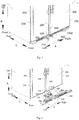
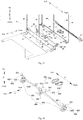
- the side-by-side refrigerator 1 includes a refrigerator body 100, a left door body 200, a right door body 300, a left door member 500, a right door member 600, a left pedal member 700 and a right pedal member 800.
- the left door body 200 and the right door body 300 are rotatably disposed on the refrigerator body 100.
- the left door member 500 is disposed on the refrigerator body 100 and is movable between a left opening position in which the left door body 200 is opened and a left closing position in which the left door body 200 is allowed to be closed.
- the right door member 600 is disposed on the refrigerator body 100 and is movable between a right opening position in which the right door body 300 is opened and a right closing position in which the right door body 300 is allowed to be closed.
- the left pedal member 700 is connected with the right door member 600 and corresponding to the left door body 200 in an up and down direction, and the left pedal member 700 is movable between a left stepping position and a left lifting position.
- the right door member 600 is driven to move from the right closing position to the right opening position.
- the right pedal member 800 is connected with the left door member 500 and corresponding to the right door body 300 in the up and down direction, and the right pedal member 800 is movable between a right stepping position and a right lifting position.
- the left door member 500 is driven to move from the left closing position to the left opening position.
- the left and right direction is illustrated by the arrows A in Figs. 1-7 , 9-18 and 23 .
- the up and down direction is illustrated by the arrows B in Figs. 1-16 and 18-23 .
- the front and rear direction is illustrated by the arrows C in Figs. 1-17 and 19-23 .
- the user may step the right pedal member 800 with his foot to move the right pedal member from the right lifting position to the right stepping position, such that the right pedal member 800 may drive the left door member 500 to move from the left closing position to the left opening position so as to open the left door 200.
- the right pedal member 800 when the right pedal member 800 is in the right lifting position, the left door member 500 is in the left closing position and the left door 200 is closed; when the right pedal member 800 is in the right stepping position, the left door member 500 is in the left opening position and the left door 200 is open.
- the user may step the left pedal member 700 with his foot to move the left pedal member from the left lifting position to the left stepping position, such that the left pedal member 700 may drive the right door member 600 to move from the right closing position to the right opening position so as to open the right door 300.
- the left pedal member 700 is in the left lifting position
- the right door member 600 is in the right closing position and the right door 300 is closed
- the left pedal member 700 is in the left stepping position
- the right door member 600 is in the right opening position and the right door 300 is open.
- the left door body 200 may be opened by stepping the right pedal member 800 and the right door body 300 may be opened by stepping the left pedal member 700, so that in the processes of opening the left door body 200 and the right door body 300, the left door body 200 and the right door body 300 will not interfere with feet or legs of the user, and thus it is easier and more convenient for the user to open the left door body 200 and the right door body 300.
- the door of the side-by-side refrigerator 1 is easy and convenient to be opened.
- the right pedal member 800 is corresponding to the right door body 300 in the up and down direction, i.e., the right pedal member 800 may be located below the right door body 300.
- the right pedal member 800 may be located outside of a horizontal projection of the left door body 200 and may be located within a horizontal projection of the right door body 300.
- the right pedal member 800 may be located at a right side of the horizontal projection of the left door body 200.
- the left pedal member 700 is corresponding to the left door body 200 in the up and down direction, i.e., the left pedal member 700 may be located below the left door body 200.
- the left pedal member 700 may be located outside of the horizontal projection of the right door body 300 and may be located within the horizontal projection of the left door body 200.
- the left pedal member 700 may be located at a left side of the horizontal projection of the right door body 300.
- the left door body 200 drives the left door member 500 to move from the left opening position to the left closing position, and thus the left door member 500 can drive the right pedal member 800 to move from the right stepping position to the right lifting position.
- the right door body 300 drives the right door member 600 to move from the right opening position to the right closing position, and thus the right door member 600 can drive the left pedal member 700 to move from the left stepping position to the left lifting position.
- the left door body 200 may be disposed on the refrigerator body 100 via a left hinge
- the right door body 300 may be disposed on the refrigerator body 100 via a right hinge.
- the side-by-side refrigerator 1 further includes a bracket 400, in which the left door member 500, the right door member 600, the left pedal member 700 and the right pedal member 800 are disposed on the bracket 400 respectively.
- a bracket 400 By disposing the bracket 400 on the refrigerator body 100, it is easy and convenient to dispose the left door member 500, the right door member 600, the left pedal member 700 and the right pedal member 800 on the refrigerator body 100.
- the bracket 400 may be disposed on a front surface 110 of the refrigerator body 100 and may be located below the left door body 200 and the right door body 300. In other words, the bracket 400 may be disposed on the front surface 110 of a lower portion of the refrigerator body 100.
- the left door member 500 and the left pedal member 700 are adjacent to a right edge 240 of the left door body 200, and the right door member 600 and the right pedal member 800 are adjacent to a left edge 340 of the right door body 300.
- the left door member 500 is away from the left hinge and the right door member 600 is away from the right hinge, such that the left door member 500 and the left pedal member 700 can be arranged compactly
- the right door member 600 and the right pedal member 800 can be arranged compactly and it is easy for the user to open the left door body 200 and the right door body 300 with less effort.
- the left door member 500 is adjacent to the right edge 240 of the left door body 200, when the user steps the right pedal member 800 to open the left door body 200, an action point of a force acted on the left door body 200 by the left door member 500 is away from the left hinge, such that the force acted on the left door body 200 by the left door member 500 has the maximum force arm, and thus the user can open the left door body 200 with a little effort.
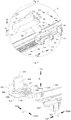
- the side-by-side refrigerator 1 may further includes a first shaft 900 and a second shaft 1000.
- the first shaft 900 and the second shaft 1000 may be pivotally disposed on the bracket 400 and be spaced from each other in the front and rear direction and in the up and down direction, the second shaft 1000 defines a left end connected with the left door member 500 and a right end connected with the right pedal member 800, and the first shaft 900 defines a right end connected with the right door member 600 and a left end connected with the left pedal member 700.
- the left door member 500 is disposed on the bracket 400 and rotated between the left opening position and the left closing position
- the right door member 600 is disposed on the bracket 400 and rotated between the right opening position and the right closing position
- the left pedal member 700 is rotated between the left stepping position and the left lifting position
- the right pedal member 800 is rotated between the right stepping position and the right lifting position.
- the first shaft 900 and the second shaft 1000 being spaced from each other both in the up and down direction and in the front and rear direction, the first shaft 900 and the second shaft 1000 are prevented from interfering with the left pedal member 700, the left door member 500, the right pedal member 800 and the right door member 600.
- first shaft 900 and the second shaft 1000 By disposing the first shaft 900 and the second shaft 1000, it is easier to dispose the left pedal member 700, the left door member 500, the right pedal member 800 and the right door member 600 on the bracket 400.
- first shaft 900 may be parallel with the second shaft 1000, and first shaft 900 and the second shaft 1000 are extended in the left and right direction.
- a fixed end of the left door member 500 (a lower end of the left door member 500) may be connected with a left end of the second shaft 1000, a free end of the left door member 500 (an upper end of the left door member 500) may be extended upwards and located between a lower portion of the left door body 200 and the refrigerator body 100.
- a fixed end of the right door member 600 (a lower end of the right door member 600) may be connected with a right end of the first shaft 900, a free end of the right door member 600 (an upper end of the right door member 600) may be extended upwards and located between a lower portion of the right door body 300 and the refrigerator body 100.
- the free end of the left door member 500 may contact with the lower portion of the left door body 200 and the free end of the right door member 600 may contact with the lower portion of the right door body 300.
- the first shaft 900 is located above the second shaft 1000, the left compartment is a freezing chamber and the right compartment is a refrigerating chamber.
- a left power-assisted opening mechanism consists of the left door member 500, the second shaft 1000 and the right pedal member, and a right power-assisted opening mechanism consists of the right door member 600, the first shaft 900 and the left pedal member 700.
- the left door member 500, the second shaft 1000, and the right pedal member 800 are formed integrally, and the right door member 600, the first shaft 900 and the left pedal member 700 are formed integrally.
- structural strengths of the left power-assisted opening mechanism and the right power-assisted opening mechanism can be improved, producing processes of the left power-assisted opening mechanism and the right power-assisted opening mechanism can be simplified and producing costs of the left power-assisted opening mechanism and the right power-assisted opening mechanism can be reduced.
- the left door member 500, the second shaft 1000, and the right pedal member 800 are formed by integral injection molding
- the right door member 600, the first shaft 900 and the left pedal member 700 are formed by integral injection molding.
- the left pedal member 700 and the right pedal member 800 may be configured as pedals (i.e., the left pedal member is a pedal and the right pedal member also may be a pedal), the left door member 500 and the right door member 600 may be configured as plates (i.e., the left door member 500 is a plate and the right door member 600 is a plate), the right pedal member 800 is aligned with the right door member 600 and the left pedal member 700 is aligned with the left door member 500.
- the left pedal member 700 and the right pedal member 800 By configuring the left pedal member 700 and the right pedal member 800 as pedals, contact areas between the user's feet and the left pedal member 700 and between the user's feet and the right pedal member 800 can be increased, and thus it is easier for the user to step the left pedal member and the right pedal member 800.
- the left door member 500 and the right door member 600 By configuring the left door member 500 and the right door member 600 as plates, contact areas between the left door member 500 and the left door body 200 and between the right door member 600 and the right door body 300 can be increased, and thus it is much easier for the user to open the left door body 200 and the right door body 300.
- the left door member 500 and the left pedal member 700 are arranged compactly, and the right door member 600 and the right pedal member 800 are arranged compactly.
- antiskid stripes 1100 may be formed in an upper surface of the left pedal member 700 and may also be formed in an upper surface of the right pedal member 800, such that friction forces between the user's feet and the left pedal member 700 and between the user's feet and the right pedal member 800 can be improved, thus performing a skid resistance function and further making it easier for the user to operate.
- the bracket 400 further includes a rear frame 410 and a front frame 420.
- the rear frame 410 has an L-shaped cross-section and has a first vertical portion 411 and a first horizontal portion 413, and a first support plate 412 is disposed on the first vertical portion 411 and defines a first clamping groove 414 and a second clamping groove 415.
- the front frame 420 has an inverted L-shaped cross-section and has a second vertical portion 421 and a second horizontal portion 427, a second support plate 422 is disposed on the second vertical portion 421 and is spaced from the first support plate 412 in the right and left direction, and the second support plate 422 defines a third clamping groove 423 and a fourth clamping groove 424.
- the first shaft 900 is pivotally fitted in the first clamping groove 414 and the third clamping groove 423
- the second shaft 1000 is pivotally fitted in the second clamping groove 415 and the fourth clamping groove 424.
- a left door member window 428 and a right door member window 429 are formed in the second horizontal portion 427, a left pedal member window 425 and a right pedal member window 426 are formed in the second vertical portion 421, a free end 510 of the left door member 500 is extended upwards and passed through the left door member window 428 and a free end 610 of the right door member 600 is extended upwards and passed through the right door member window 429, and a free end 710 of the left pedal member 710 (a front end of the left pedal member 700) is extended forwards and passed through the left pedal member window 425 and a free end 810 of the right pedal member 800 (a front end of the right pedal member 800) is extended forwards and passed through the right pedal member window 426.
- a space configured to receive a part of the left door member 500, a part of the right door member 600, a part of the left pedal member 700, a part of the right pedal member 800, the first shaft 900 and the second shaft 1000 is defined, such that the side-by-side refrigerator 1 has a simple and artistic appearance and the left door member 500, the right door member 600, the left pedal member 700, the right pedal member 800, the first shaft 900 and the second shaft 1000 can be protected.
- first clamping groove 414 and the second clamping groove 415 in the first support plate 412 of the rear frame 410 and defining the third clamping groove 423 and the fourth clamping groove 424 in the second support plate 422 of the front frame 420 it is much easier to dispose the first shaft 900 and the second shaft 1000 on the bracket pivotally.
- a rear end of the second horizontal portion 427 of the front frame 420 contacts with an upper end of the first vertical portion 411 of the rear frame 410, and a lower end of the second vertical portion 421 of the front frame 420 contacts with a front end of the horizontal portion 413 of the rear frame 410, and thus a chamber with a general rectangle shape is defined by the rear frame 410 with the L-shaped cross-section and the front frame 420 with the inverted L-shaped cross-section.
- the first support plate 412 is disposed on a front surface of the first vertical portion 411 of the rear frame 410 (a surface of the first vertical portion 411 close to the user) and is extended forwards.
- the second support plate 422 is disposed on a rear surface of the second vertical portion 421 of the front frame 420 (a surface of the vertical portion away from the user) and is extended backwards.
- the first clamping groove 414 and the second clamping groove 415 may be formed in the first support plate 412 and spaced from each other in the up and down direction
- the third clamping groove 423 and the fourth clamping groove 424 may be formed in the second support plate 422 and spaced from each other in the up and down direction.
- both the first support plate 412 and the second support plate 422 may be oriented in the front and rear direction, rear ends of the first clamping groove 414 and the second clamping groove 415 may be configured as semicircles, and front ends of the third clamping groove 423 and the fourth clamping groove 424 may be configured as semicircles, such that the first shalt 900 can be fitted in the first clamping groove 414 and the third clamping groove 423 stably and the second shaft 1000 may be fitted in the second clamping groove 415 and the fourth clamping groove 424 stably.
- first support plates 412 There may be a plurality of first support plates 412, and the plurality of first support plates 412 are disposed on the first vertical portion 411 of the rear frame 410 and spaced from each other in the left and right direction.
- second support plates 422 There may be a plurality of second support plates 422, and the plurality of second support plates 422 are disposed on the second vertical portion 421 of the front frame 420 and spaced from each other in the left and right direction.
- Each first support plate 412 is spaced from each second support 422 in the left and right direction.
- the first support plate 412 and the rear frame 410 are formed integrally, and the second support plate 422 and the front frame 420 are formed integrally.
- the first support plate 412 and the rear frame 410 are integrally formed by injection molding, and the second support plate 422 and the front frame 420 are integrally formed by injection molding, and thus the structural strength is improved, the producing process is simplified and the producing cost is reduced.
- lower ends of the left pedal window 425 and the right pedal window 426 are open, such that it is easy to dispose the left pedal member 700 and the right pedal member 800, i.e., it is easy to dispose the left power-assisted opening mechanism and the right power-assisted opening mechanism.
- the rear frame 410 further includes a first side plate 430
- the front frame 420 further includes a second side plate 440
- one of the first side plate 430 and the second side plate 440 defines a sliding groove 450 and the other thereof has a sliding rail 460 which is fitted in the sliding groove 450 and movable in the front and rear direction within the sliding groove 450.
- first side plates 430 there may be two first side plates 430, and one is disposed at a left side of the rear frame 410 and the other one is disposed at a right side of the rear frame 410; there may be two second side plates 440, one is disposed at a left side of the front frame 420 and the other one is disposed at a right side of the front frame 420.
- the first side plate 430 and the rear frame 410 are formed integrally, and the second side plate 440 and the front frame 420 are formed integrally.
- the first side plate 430 and the rear frame 410 are integrally formed by injection molding, and the second side plate 440 and the front frame 420 are integrally formed by injection molding, and thus the structural strength is improved, the producing process is simplified and the producing cost is reduced.
- the side-by-side refrigerator 1 further includes a bottom beam cover 1200 disposed on a bottom beam 140 of the refrigerator body 100 and formed with the front frame 420 integrally.
- the bottom beam cover 1200 is formed with the front frame 420 by injection molding integrally, and thus the structural strength is improved, the producing process is simplified and the producing cost is reduced.
- the side-by-side refrigerator 1 includes a first elastic member (not shown) and a second elastic member 1300.
- the first elastic member is disposed between the left pedal member 700 and the bracket 400 and is configured to push the left pedal member 700 from the left stepping position to the left lifting position.
- the second elastic member 1300 is disposed between the right pedal member 800 and the bracket 400 and is configured to push the right pedal member 800 to the right lifting position from the right stepping position.
- the first elastic member when the user steps the left pedal member 700, i.e., when the left pedal member 700 is in the left stepping position, the first elastic member is compressed; when the user's feet are removed from the left pedal member 700, the first elastic member moves the left pedal member 700 from the left stepping position to the left lifting position.
- the right pedal member 800 when the user steps the right pedal member 800, i.e., when the right pedal member 800 is in the right stepping position, the second elastic member 1300 is compressed; when the user's feet are removed from the right pedal member 800, the second elastic member 1300 moves the right pedal member 800 from the right stepping position to the right lifting position.
- the left pedal member 700 and the right door member 600 can be reset when the user's feet are removed from the left pedal member 700, and the right pedal member 800 and the left door member 500 can be reset when the user's feet are removed from the right pedal member 800.
- a first end of the first elastic member is connected with a lower surface of the left pedal member 700 and a second end of the first elastic member is connected with an upper surface of the first horizontal portion 413 of the rear frame 410.
- the first end of the second elastic member 1300 (an upper end of the second elastic member 1300 in Fig. 8 ) is connected with a lower surface of the right pedal member 800 and a second end of the second elastic member 1300 (a lower end of the second elastic member 1300 in Fig. 8 ) is connected with the upper surface of the first horizontal portion 413 of the rear frame 410.
- a left boss is disposed on a lower surface of the left door body 200, and the free end 510 of the left door member 500 is located between the left boss and the front surface 110 of the refrigerator body 100;
- a right boss is disposed on a lower surface of the right door body 300, and the free end 610 of the right door member 600 is located between the right boss and the front surface 110 of the refrigerator body 100.
- the left door member 500 applies a force to the left boss and the right door member 600 applies a force to the right boss.
- the left door member 500 is prevented from applying a force to the left door body directly; by disposing the right boss on the lower surface of the right door body 300, the right door member 600 is prevented from applying a force to the right door body 300 directly.
- the left door body 200 and the right door body 300 will not be damaged after having been opened for many times, thus increasing a working life of the left door body 200 and the right door body 300, i.e., increasing a working life of the side-by-side refrigerator 1.
- the left boss is disposed on the lower surface of the left door body 200 detachably, and the right boss is disposed on the lower surface of the right door body 300 detachably.
- the left boss and the right boss are damaged, they can be replaced.
- a cost of replacing the left boss and the right boss is much less than that of replaying the left door body 200 and the right door body 300.
- the side-by-side refrigerator 1 may further includes a first shaft 900 and a second shaft 1000.
- the first shaft 900 and the second shaft 1000 may be pivotally disposed on the bracket 400 and be spaced from each other in the up and down direction, the second shaft 1000 is connected with the left door member 500 and defines a right end connected with the right pedal member 80, and the first shaft 900 is connected with the right door member 600 and defines a left end connected with the left pedal member 700.
- the left door member 500 is disposed on the bracket 400 and rotated between the left opening position and the left closing position
- the right door member 600 is disposed on the bracket 400 and rotated between the right opening position and the right closing position
- the left pedal member 700 is rotated between the left stepping position and the left lifting position
- the right pedal member 800 is rotated between the right stepping position and the right lifting position.
- the first shaft 900 and the second shaft 1000 are spaced from each other both in the up and down direction, and thus the first shaft 900 and the second shaft 1000 are prevented from interfering with the left pedal member 700 and the right pedal member 800.
- first shaft 900 and the second shaft 1000 By disposing the first shaft 900 and the second shaft 1000, it is easier to dispose the left pedal member 700, the left door member 500, the right pedal member 800 and the right door member 600 on the bracket 400.
- first shaft 900 may be parallel with the second shaft 1000, and first shaft 900 and the second shaft 1000 are extended in the left and right direction.
- a fixed end of the left door member 500 (a lower end of the left door member 500) may be connected with a left end of the second shaft 1000, a free end of the left door member 500 (an upper end of the left door member 500) may be extended upwards and located between a lower portion of the left door body 200 and the refrigerator body 100.
- a fixed end of the right door member 600 (a lower end of the right door member 600) may be connected with a right end of the first shaft 900, a free end of the right door member 600 (an upper end of the right door member 600) may be extended upwards and located between a lower portion of the right door body 300 and the refrigerator body 100.
- the free end of the left door member 500 may contact with the lower portion of the left door body 200 and the free end of the right door member 600 may contact with the lower portion of the right door body 300.
- the first shaft 900 is located below the second shaft 1000, the left compartment is a freezing chamber and the right compartment is a refrigerating chamber.
- a left power-assisted opening mechanism consists of the left door member 500, the second shaft 1000 and the right pedal member 800, and a right power-assisted opening mechanism consists of the right door member 600, the first shaft 900 and the left pedal member 700.
- the left door member 500, the second shaft 1000, and the right pedal member 800 are formed integrally, and the right door member 600, the first shaft 900 and the left pedal member 700 are formed integrally.
- structural strengths of the left power-assisted opening mechanism and the right power-assisted opening mechanism can be improved, producing processes of the left power-assisted opening mechanism and the right power-assisted opening mechanism can be simplified and producing costs of the left power-assisted opening mechanism and the right power-assisted opening mechanism can be reduced.
- the left door member 500 is adjacent to a left edge 230 of the left door body 200
- the right door member 600 is adjacent to a right edge 330 of the right door body 300, such that the left door member 500 is adjacent to the left hinge and the right door member 600 is adjacent to the right hinge.
- the left door body 200 can be opened with a larger angle by the left door member 500
- the right door body 300 can be opened with a larger angle by the right door member 600.
- the left door body 200 and the right door body 300 have larger power-assisted travels.
- the left door body 200 can have the maximum power-assisted travel, i.e., the left door body 200 is opened with the maximum angle.
- the right door body 300 can have the maximum power-assisted travel, i.e., the right door body 300 is opened with the maximum angle.
- the left pedal member 700 is adjacent to the right edge 240 of the left door body 200
- the right pedal member 800 is adjacent to the left edge 340 of the right door body 300.
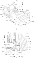
- the left door member 500 includes a first left door arm 520 and a second left door arm 530.
- the first left door arm 520 is connected with the left end of the second shaft 1000 and is adjacent to the left edge 230 of the left door body 200 and the second left door arm 530 is connected with the second shaft 1000 and is located between the first left door arm 520 and the right pedal member 800.
- the right door member 600 includes a first right door arm 620 and a second right door arm 630.
- the first right door arm 620 is connected with the right end of the first shaft 900 and is adjacent to the right edge 330 of the right door body 300 and the second right door arm 630 is connected with the first shaft 900 and is located between the first right door arm 620 and the left pedal member 700.
- each of the first left door arm 520 and the second left door arm 530 may be disposed on the bracket 400 and rotated between the left opening position and the left closing position
- each of the first right door arm 620 and the second right door arm 630 may be disposed on the bracket 400 and rotated between the right opening position and the right closing position.
- the user may step the right pedal member 800 with his foot to move the right pedal member 800 from the right lifting position to the right stepping position, such that the right pedal member 800 may drive the first left door arm 520 and the second left door arm 530 to move from the left closing position to the left opening position so as to open the left door 200.
- the user may step the left pedal member 700 with his foot to move the left pedal member from the left lifting position to the left stepping position, such that the left pedal member 700 may drive the first right door arm 620 and the second right door arm 630 to move from the right closing position to the right opening position so as to open the right door 300.
- the left door body 200 can be opened with a larger angle by the first left door arm 520 and the right door 300 can be opened with a larger angle by the first right door arm 620.
- the left door body 200 and the right door body 300 have larger power-assisted travels.
- the second left door arm 530 is away from to the left edge 230 of the left door body 200 and the second right door arm 630 is away from to the right edge 330 of the right door body 300 (i.e., the second left door arm 530 is away from to the left hinge and the second right door arm 630 is away to the right hinge)
- an action point of a force acted on the left door body 200 by the second left door arm 530 is away from the left hinge
- an action point of a force acted on the right door body 300 by the second right door arm 630 is away from the right hinge, and thus the user can open the left door 200 and the right door 300 with a little effort.
- first left door arm 520 adjacent to the left edge 230 of the left door body 200 and disposing the second left door arm 530 away from to the left edge 230 of the left door body 200
- first right door arm 620 adjacent to the right edge 330 of the right door body 300 and disposing the second right door arm 630 away from to the right edge 330 of the right door body 300
- first right door arm 620 adjacent to the right edge 330 of the right door body 300
- second right door arm 630 away from to the right edge 330 of the right door body 300, not only the user can open the right door 300 with a little effort, but also the right door body 300 can have a larger power-assisted travel.
- the second left door arm 530 contacts with the left door body 200 and the first left door arm 520 is spaced from the left door body 200 with a certain distance (such as 3mm to 20mm, preferably 10mm); in the right closing position, the second right door arm 630 contacts with the right door body 300 and the first right door arm 620 is spaced from the right door body 300 with a certain distance (such as 3mm to 20mm, preferably 10mm).
- the first left door arm 520 and the second left door arm 530 are rotated forwards (i.e., swung forwards). Since the second left door arm 530 contacts with the left door body 200, the left door body 200 is opened with a certain angle (such as 3 degrees to 5 degrees) by the second left door arm 530, and thus the left door 200 is beyond a magnetism scope of a door gasket.
- the second left door arm 530 separates from the left door body 200 and the first left door body contacts with the left door body 200 so as to continuously open the left door body 200 (at the moment, the left door 200 has been beyond the magnetism scope of the door gasket and has a certain initial velocity, and thus the left door body 200 has a small opening resistance), until the first left door arm 520 separates from the left door body 200.
- the left door body 200 can be opened with an angle of 5 degrees to 20 degrees and even be opened with an angle larger than 90 degrees by means of inertance thereof.
- the process of opening the right door body 300 is the same with that of opening the left door body 200 and is omitted herein.
- the left pedal member 700 and the second left door arm 530 may be adjacent to the right edge 240 of the left door body 200, and the right pedal member 800 and the second right door arm 630 may be adjacent to left edge 340 of the right door body 300.
- the force acted on the left door body 200 by the second left door arm 530 has the longest force arm, and thus the user can open the left door body 200 with a little effort.
- the force acted on the right door body 300 by the second right door arm 630 has the longest force arm, and thus the user can open the right door body 300 with a little effort.
- the left pedal member 700 in a position adjacent to the right edge 240 of the left door body 200 and disposing the right pedal member 800 in a position adjacent to the left edge 340 of the right door body 300, the left pedal member 700, the second left door arm 530, the right pedal member 800 and the second right door arm 630 can be arranged compactly.
- the first left door arm 520, the second left door arm 530, the first right door arm 620 and the second right door arm 630 may be configured as rods.
- the left pedal member 700 includes a left support rod 720 connected with the left end of the first shaft 900 and a left pedal 730 disposed on the left support rod 720
- the right pedal member 800 includes a right support rod 820 connected with the right end of the second shaft 1000 and a right pedal 830 disposed on the right support rod 820.
- the first left door arm 520, the second shaft 1000 and the right support rod 820 are formed integrally
- the first right door arm 620, the first shaft 900 and the left support rod 720 are formed integrally.
- the left pedal member 700 and the right pedal member 800 have artistic appearances, and the contact areas between the user's feet and the right pedal member 800 and the left pedal member 700 are increased, such that it is easier for the user to step the right pedal member 800 and the left pedal member 700.
- antiskid stripes may be formed in an upper surface of the left pedal 730 and may also be formed in an upper surface of the right pedal 830, such that friction forces between the user's feet and the left pedal 730 and between the user's feet and the right pedal 830 can be improved, thus performing a skid resistance function and further making it easier for the user to operate.
- the first left door arm 520, the second shaft 1000 and the right support rod 820 are made of a steel bar with a diameter of 8mm by bending, and a first end of the steel bar is bent forwards with an angle of 90 degrees so as to from the right support rod 820, and a second end of the steel bar is bent upwards with an angle of 90 degrees so as to form the first left door arm 520.
- the first right door arm 620, the first shaft 900 and the left support rod 720 also are made of a steel bar with a diameter of 8mm by bending, and a manufacturing method thereof is the same with that in above descriptions.
- the second left door arm 530 and the second right door arm 630 are made of steel, and the second left door arm 530 is welded on the second shaft 1000 and the second right door arm 630 is welded on the first shaft 900.
- the first left door arm 520 and the second left door arm 530 are oriented in the up and down direction; in the right closing position, the first right door arm 620 and the second right door arm 630 are oriented in the up and down direction.
- the left support rod 720 and the left pedal 730 are oriented in a front and rear position; in the right lifting position, the right support rod 820 and the right pedal 830 are oriented in the front and rear direction.
- the second shaft 1000 is orthogonal to each of the first left door arm 520, the second left door arm 530, the right support rod 820 and the right pedal 830, and the first shaft 900 is orthogonal to each of the first right door arm 620, the second right door arm 630, the left support rod 720 and the left pedal 730.
- a first left boss 250 and a second left boss 260 are disposed on a lower surface 220 of the left door body 200, a free end 521 of the first left door arm 520 is located between the first left boss 250 and a front surface 110 of the refrigerator body 100, and a free end 531 of the second left door arm 530 is located between the second left boss 260 and the front surface 110 of the refrigerator body 100.
- a first right boss 350 and a second right boss 360 are disposed on a lower surface 320 of the right door body 300, a free end 621 of the first right door arm 620 is located between the first right boss 360 and the front surface 110 of the refrigerator body 100, and a free end 631 of the second right door arm 630 is located between the second right boss 360 and the front surface 110 of the refrigerator body 100.
- the first left door arm 520 applies a force to the first left boss 250 and the second left door arm 530 applies a force to the second left boss 260
- the first right door arm 620 applies a force to the first right boss 350
- the second right door arm 630 applies a force to the second right boss 360.
- the first left boss 250 and the second left boss 260 are prevented from applying a force to the left door body 200 directly; by disposing the first right boss 350 and the second left door boss 360 on the lower surface 320 of the right door body 300, the first right door arm 620 and the second left door arm 630 are prevented from applying a force to the right door body 300 directly. Therefore, the left door body 200 and the right door body 300 will not be damaged after having been opened for many times, thus increasing a working life of the left door body 200 and the right door body 300, i.e., increasing a working life of the side-by-side refrigerator 1.
- the first left boss 250 and the second left boss 260 are disposed on the lower surface 220 of the left door body 200 detachably, and the first right boss 350 and the second right boss 360 are disposed on the lower surface 320 of the right door body 300 detachably.
- the first left boss 250, the second left boss 260, the first right boss 350 and the second right boss 360 are damaged, they can be replaced.
- a cost of replacing the first left boss 250, the second left boss 260, the first right boss 350 and the second right boss 360 is much less than that of replaying the left door body 200 and the right door body 300.
- the second left door arm 530 contacts with the second left boss 260 and the first left door arm 520 is spaced from the first left boos 250 with a certain distance (such as 3mm-20mm, preferably 10mm); in the right closing position, the second right door arm 630 contacts with the second right boss 360 and the first right door arm 620 is spaced from the first right boss 350 with a certain distance (such as 3mm-20mm, preferably 10mm).
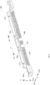
- the bracket 400 includes a first support 470, a second support 480 and a third support 490.
- the first support 470 is located below the left door body 200 and is adjacent to the left edge 230 of the left door body 200.
- the second support 480 is located below the left door body 200 and/or the right door body 300.
- the third support 490 is located below the right door body 300 and is adjacent to the right edge 330 of the right door body 300.
- the right end of the first shaft 900 is supported on the third support 490
- the left end of the second shaft 1000 is supported on the first support 470
- the left end of the first shaft 900 and the right end of the second shaft 1000 are supported on the second support 480.
- each of the first support 470, the second support 480 and the third support 490 includes a third vertical portion and a third horizontal portion.
- the third vertical portion is disposed on a front surface of the bottom beam 140 of the refrigerator body 100, and a first shaft hole 481 and a second shaft hole 482 penetrated through the third vertical portion in the left and right direction are spaced from each other in the up and down direction.
- the third horizontal portion is disposed on a lower face of the refrigerator body 100, and a front edge of the third horizontal portion is connected with a lower edge of the third vertical portion.
- the side-by-side refrigerator 1 further includes a first reinforcer, a second reinforcer and a third reinforcer.
- the first reinforcer, the second reinforcer and the third reinforcer may be disposed on a rear surface of the bottom beam 140 of the refrigerator body 100 and spaced from one another.
- the first support 470 may be disposed on the bottom beam 140 of the refrigerator body 100 and the first reinforcer by a first fastener.
- the second support 480 may be disposed on the bottom beam 140 of the refrigerator body 100 and the second reinforcer by a second fastener.
- the third support 490 may be disposed on the bottom beam 140 of the refrigerator body 100 and the third reinforcer by a third fastener.
- first reinforcer By disposing the first reinforcer, the second reinforcer and the third reinforcer, the first support 470, the second support 480, the third support 490 can be disposed on the bottom beam 140 of the refrigerator body 100 stably and can bear larger forces.
- the first fastener, the second fastener and the third fastener may be screws.
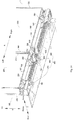
- the side-by-side refrigerator 1 further includes a decoration cover 1400 disposed on the bottom beam 140 of the refrigerator body 100.
- a first gap 1411 and a second gap 1422 are formed in a rear edge of an upper surface 1410 of the decoration cover 1400, and a third gap 1421 and a fourth gap 1422 are formed in a lower edge of a front surface 1420 of the decoration cover 1400.
- the free end 510 of the left door member 500 is extended upwards and passed through the first gap 1411
- the free end 610 of the right door member 600 is extended upwards and passed through the second gap 1412
- the free end 710 of the left pedal member 700 is extended forwards and passed through the third gap 1421
- the free end 810 of the right pedal member 800 is extended forwards and passed through the fourth gap 1422.
- the decoration cover 1400 By disposing the decoration cover 1400 on the bottom beam 140 of the refrigerator body 100, the left door member 500, the right door member 600, the left pedal member 700 and the right pedal member 800 can be covered up, thus providing an artistic appearance with the side-by-side refrigerator 1.
- a first opening 1423 and a second opening 1424 are formed in the decoration cover 1400.
- the free end 521 of the first left door arm 520 is extended upwards and passed through the first gap 1411
- the free end 531 of the second left door arm 530 is extended upwards and institutions through the first opening 1423
- the free end 621 of the first right door arm 620 is extended upwards and passed through the second gap 1412
- the free end 632 of the second right door arm 630 is extended upwards and passed through the second opening 1424.
Landscapes
- Engineering & Computer Science (AREA)
- Chemical & Material Sciences (AREA)
- Combustion & Propulsion (AREA)
- Physics & Mathematics (AREA)
- Mechanical Engineering (AREA)
- Thermal Sciences (AREA)
- General Engineering & Computer Science (AREA)
- Refrigerator Housings (AREA)
Claims (7)
- Reihenkühlschrank, umfassend:einen Kühlschrankkörper (100),einen linken Türkörper (200) und einen rechten Türkörper (300), die jeweils verschwenkbar an dem Kühlschrankkörper (100) angeordnet sind,ein linkes Türelement (500), das an dem Kühlschrankkörper (100) angeordnet ist und zwischen einer linken Öffnungsstellung, in der der linke Türkörper (200) geöffnet ist, und einer linken Schließstellung, in der der linke Türkörper (200) schließbar ist, verstellbar ist,ein rechtes Türelement (600), das an dem Kühlschrankkörper (100) angeordnet ist und zwischen einer rechten Öffnungsstellung, in der der rechte Türkörper (300) geöffnet ist, und einer rechten Schließstellung, in der der rechte Türkörper (300) schließbar ist, verstellbar ist,ein linkes Pedalelement (700), das mit dem rechten Türelement (600) verbunden ist und mit dem linken Türkörper (200) in einer Aufwärts- und Abwärtsrichtung korrespondiert und zwischen einer linken Trittstellung und einer linken Hebestellung verstellbar ist, wobei wenn das linke Pedalelement (700) von der linken Hebestellung in die linke Trittstellung verstellt ist, das rechte Türelement (600) angetrieben ist, sich von der rechten Schließstellung in die rechte Öffnungsstellung zu verstellen, undein rechtes Pedalelement (800), das mit dem linken Türelement (500) verbunden ist und mit dem rechten Türkörper (300) in der Aufwärts- und Abwärtsrichtung korrespondiert und zwischen einer rechten Trittstellung und einer rechten Hebestellung verstellbar ist, wobei wenn das rechte Pedalelement (800) von der rechten Hebestellung in die rechte Trittstellung verstellt ist, das linke Türelement (500) angetrieben ist, sich von der linken Schließstellung in die linke Öffnungsstellung zu verstellen,einen Halter (400), der an einer Vorderseite (110) des Kühlschrankkörpers (100) angeordnet ist und unterhalb des linken Türkörpers (200) und des rechten Türkörpers (300) angeordnet ist, wobei jeweils das linke Türelement (500), das rechte Türelement (600), das linke Pedalelement (700) und das rechte Pedalelement (800) an einem Halter (400) angeordnet sind, undeine erste Welle (900) und eine zweite Welle (1000), die schwenkbar an dem Halter (400) angeordnet sind und in der Aufwärts- und Abwärtsrichtung zueinander beabstandet sind, wobei die zweite Welle (1000) mit dem linken Türelement (500) verbunden ist und ein mit dem rechten Pedalelement (800) verbundenes rechtes Ende und ein linkes Ende definiert, wobei die erste Welle (900) mit dem rechten Türelement (600) verbunden ist und ein mit dem linken Pedalelement (700) verbundenes linkes Ende und ein rechtes Ende definiert,dadurch gekennzeichnet,dass das linke Türelement (500) einen ersten linken Türhebel (520), der mit dem linken Ende der zweiten Welle (1000) verbunden ist und an einen linken Rand (230) des linken Türkörpers (200) benachbart angeordnet ist, und einen zweiten linken Türhebel (530) aufweist, der mit der zweiten Welle (1000) verbunden ist und zwischen dem ersten linken Türhebel (520) und dem rechten Pedalelement (800) angeordnet ist, unddass das rechte Türelement (600) einen ersten rechten Türhebel (620), der mit dem rechten Ende der ersten Welle (900) verbunden ist und an einem rechten Rand (330) des rechten Türkörpers (300) benachbart angeordnet ist, und einen zweiten rechten Türhebel (630) aufweist, der mit der ersten Welle (900) verbunden ist und zwischen dem ersten rechten Türhebel (620) und dem linken Pedalelement (700) angeordnet ist.
- Kühlschrank nach Anspruch 1, weiterhin umfassend:ein erstes elastisches Element, das zwischen dem linken Pedalelement (700) und dem Halter (400) angeordnet ist und zum Schieben des linken Pedalelements (700) von der linken Trittstellung in die linke Hebestellung konfiguriert ist, undein zweites elastisches Element (1300), das zwischen dem rechten Pedalelement (800) und dem Halter (400) angeordnet ist und zum Schieben des rechten Pedalelements (800) in die rechte Hebestellung von der rechten Trittstellung konfiguriert ist.
- Kühlschrank nach Anspruch 1 oder 2, wobei das linke Pedalelement (700) und der zweite linke Türhebel (530) benachbart eines rechten Rands (240) des linken Türkörpers (200) angeordnet sind und wobei das rechte Pedalelement (800) und der zweite rechte Türhebel (630) benachbart eines linken Rands (340) des rechten Türkörpers (300) angeordnet sind.
- Kühlschrank nach einem der Ansprüche 1 bis 3, wobei der erste linke Türhebel (520), der zweite linke Türhebel (530), der erste rechte Türhebel (620) und der zweite rechte Türhebel (630) als Stangen ausgebildet sind,
wobei das linke Pedalelement (700) eine mit dem linken Ende der ersten Welle (900) verbundene linke Stützstange (720) und ein an der linken Stützstange (720) angeordnetes linkes Pedal (730) aufweist, wobei das rechte Pedalelement (800) eine mit dem rechten Ende der zweiten Welle (1000) verbundene rechte Stützstange (820) und ein an der rechten Stützstange (820) angeordnetes rechtes Pedal (830) aufweist,
wobei der erste linke Türhebel (520), die zweite Welle (1000) und die rechte Stützstange (820) einstückig ausgebildet sind und wobei der erste rechte Türhebel (620), die erste Welle (900) und die linke Stützstange (720) einstückig ausgebildet sind. - Kühlschrank nach einem der Ansprüche 1 bis 4, wobei eine erste linke Halterung (250) und eine zweite linke Halterung (260) an einer Unterseite (220) des linken Türkörpers (200) angeordnet sind, wobei ein freies Ende (521) des linken Türhebels (520) zwischen der ersten linken Halterung (250) und einer Vorderseite (110) des Kühlschrankkörpers (100) angeordnet ist und wobei ein freies Ende (531) des zweiten linken Türhebels (530) zwischen der zweiten linken Halterung (260) und der Vorderseite (110) des Kühlschrankkörpers (100) angeordnet ist,
wobei eine erste rechte Halterung (350) und eine zweite rechte Halterung (360) an einer Unterseite (320) des rechten Türkörpers (300) angeordnet sind, wobei ein freies Ende (621) des ersten rechten Türhebels (620) zwischen der ersten rechten Halterung (350) und der Vorderseite (110) des Kühlschrankkörpers (100) angeordnet ist und wobei ein freies Ende (631) des zweiten rechten Türhebels (630) zwischen der zweiten rechten Halterung (360) und der Vorderseite (110) des Kühlschrankkörpers (100) angeordnet ist. - Kühlschrank nach einem der Ansprüche 1 bis 5, wobei der Halter (400) Folgendes aufweist:eine erste Stütze (470), die unterhalb des linken Türkörpers (200) und an den linken Rand (230) des linken Türkörpers (200) benachbart angeordnet ist,eine zweite Stütze (480), die unterhalb des linken Türkörpers (200) und/oder des rechten Türkörpers (300) angeordnet ist, undeine dritte Stütze (490), die unterhalb des rechten Türkörpers (300) und an den rechten Rand (330) des rechten Türkörpers (300) benachbart angeordnet ist,wobei das rechte Ende der ersten Welle (900) an der dritten Stütze (490) gestützt ist, wobei das linke Ende der zweiten Welle (1000) an der ersten Stütze (470) gestützt ist und wobei das linke Ende der ersten Welle (900) und das rechte Ende der zweiten Welle (1000) an der zweiten Stütze (480) gestützt sind.
- Kühlschrank nach einem der Ansprüche 1 bis 6, weiterhin umfassend eine Dekorationsabdeckung (1400), die an einem unteren Balken (140) des Kühlschrankkörpers (100) angeordnet ist, wobei eine erste Aussparung (1411) und eine zweite Aussparung (1412) in einem hinteren Rand einer Oberseite (1410) der Dekorationsabdeckung (1400) ausgebildet sind und wobei eine dritte Aussparung (1421) und eine vierte Aussparung (1422) in einem unteren Rand einer Vorderseite (1420) der Dekorationsabdeckung (1400) ausgebildet sind,
wobei ein freies Ende (510) des linken Türelements (500) nach oben gestreckt ist und durch die erste Aussparung (1411) greift, wobei ein freies Ende (610) des rechten Türelements (600) nach oben gestreckt ist und durch die zweite Aussparung (1412) greift, wobei ein freies Ende (710) des linken Pedalelements (700) nach vorne gestreckt ist und durch die dritte Aussparung (1421) greift und wobei ein freies Ende (810) des rechten Pedalelements (800) nach vorne gestreckt ist und durch die vierte Aussparung (1422) greift.
Applications Claiming Priority (3)
| Application Number | Priority Date | Filing Date | Title |
|---|---|---|---|
| CN201220407254.1U CN202885388U (zh) | 2012-02-27 | 2012-08-16 | 对开门冰箱 |
| CN201210292365.7A CN103017435B (zh) | 2012-02-27 | 2012-08-16 | 对开门冰箱 |
| PCT/CN2013/077764 WO2014026506A1 (zh) | 2012-08-16 | 2013-06-24 | 对开门冰箱 |
Publications (3)
| Publication Number | Publication Date |
|---|---|
| EP2886980A1 EP2886980A1 (de) | 2015-06-24 |
| EP2886980A4 EP2886980A4 (de) | 2016-04-20 |
| EP2886980B1 true EP2886980B1 (de) | 2017-09-20 |
Family
ID=50101273
Family Applications (1)
| Application Number | Title | Priority Date | Filing Date |
|---|---|---|---|
| EP13829429.3A Not-in-force EP2886980B1 (de) | 2012-08-16 | 2013-06-24 | Aufgereihte kühlvorrichtungen |
Country Status (2)
| Country | Link |
|---|---|
| EP (1) | EP2886980B1 (de) |
| WO (1) | WO2014026506A1 (de) |
Families Citing this family (2)
| Publication number | Priority date | Publication date | Assignee | Title |
|---|---|---|---|---|
| DE102015006213A1 (de) * | 2015-05-13 | 2016-11-17 | Liebherr-Hausgeräte Lienz Gmbh | Kühl- und/oder Gefriergerät |
| US10100566B1 (en) * | 2016-09-14 | 2018-10-16 | Suwandi Chandra | Concealed door opening system |
Family Cites Families (8)
| Publication number | Priority date | Publication date | Assignee | Title |
|---|---|---|---|---|
| US5622416A (en) * | 1995-05-15 | 1997-04-22 | Hoshizaki America Inc. | Foot pedal door opener device for a two-door reach-in cabinet |
| US6328392B1 (en) * | 1999-12-14 | 2001-12-11 | Hoshizaki America, Inc. | Foot pedal door opener device for a reach-in cabinet and method of mounting same |
| CN2438071Y (zh) * | 2000-05-24 | 2001-07-04 | 海尔集团公司 | 电冰箱的足踏开门装置 |
| CN100398949C (zh) * | 2003-05-22 | 2008-07-02 | 乐金电子(天津)电器有限公司 | 泡菜电冰箱 |
| KR20090043972A (ko) * | 2007-10-30 | 2009-05-07 | 엘지전자 주식회사 | 냉장고 |
| CN201412998Y (zh) * | 2009-04-03 | 2010-02-24 | 潘舒伟 | 冰箱冷冻门踏板助开装置 |
| CN201628440U (zh) * | 2009-12-23 | 2010-11-10 | 华磁科技(宁波)有限公司 | 冰箱门的开启装置 |
| CN102538337A (zh) * | 2012-02-27 | 2012-07-04 | 合肥美的荣事达电冰箱有限公司 | 冰箱 |
-
2013
- 2013-06-24 EP EP13829429.3A patent/EP2886980B1/de not_active Not-in-force
- 2013-06-24 WO PCT/CN2013/077764 patent/WO2014026506A1/zh not_active Ceased
Non-Patent Citations (1)
| Title |
|---|
| None * |
Also Published As
| Publication number | Publication date |
|---|---|
| EP2886980A4 (de) | 2016-04-20 |
| WO2014026506A1 (zh) | 2014-02-20 |
| EP2886980A1 (de) | 2015-06-24 |
Similar Documents
| Publication | Publication Date | Title |
|---|---|---|
| US20120073321A1 (en) | Refrigerator door mullion apparatus and system | |
| KR20080069434A (ko) | 양방향 개폐 가능한 도어유닛 및 이를 포함하는 냉장고 | |
| EP3936798B1 (de) | Kühlschrank | |
| CN101963425A (zh) | 冰箱 | |
| CN104727629B (zh) | 制冷设备 | |
| CN106369920A (zh) | 一种冰箱助力门把手组件及冰箱 | |
| WO2012010502A3 (en) | Storage unit with a door and a fastening mechanism for fastening the door, and refrigeration appliance having the storage unit | |
| JP6074870B2 (ja) | 冷凍冷蔵庫用キャッチャの解放装置 | |
| ES2650469T3 (es) | Refrigerador de dos puertas verticales | |
| CN102980357B (zh) | 冰箱 | |
| EP2886980A1 (de) | Aufgereihte kühlvorrichtungen | |
| US9097052B2 (en) | Refrigerator | |
| CN221279767U (zh) | 冰箱 | |
| KR100518689B1 (ko) | 터치 스위치 및 터치 스위치를 구비한 냉장고 | |
| CN216719766U (zh) | 一种烹饪器具的门控开关结构 | |
| CN108468470B (zh) | 具有折叠功能的门提手及卧式冷柜 | |
| KR200463723Y1 (ko) | 냉장고 | |
| CN203605598U (zh) | 冰箱 | |
| CN210918627U (zh) | 一种带限位开关触头的烤箱铰链 | |
| JP5606490B2 (ja) | 冷蔵庫扉 | |
| CN208251902U (zh) | 一种地铁屏蔽门故障检测装置 | |
| CN201433661Y (zh) | 一种四向门 | |
| CN217841171U (zh) | 门组件及冰箱 | |
| CN208822363U (zh) | 壶盖和电水壶 | |
| CN203947902U (zh) | 一种双向型平面控制锁 |
Legal Events
| Date | Code | Title | Description |
|---|---|---|---|
| PUAI | Public reference made under article 153(3) epc to a published international application that has entered the european phase |
Free format text: ORIGINAL CODE: 0009012 |
|
| 17P | Request for examination filed |
Effective date: 20150310 |
|
| AK | Designated contracting states |
Kind code of ref document: A1 Designated state(s): AL AT BE BG CH CY CZ DE DK EE ES FI FR GB GR HR HU IE IS IT LI LT LU LV MC MK MT NL NO PL PT RO RS SE SI SK SM TR |
|
| AX | Request for extension of the european patent |
Extension state: BA ME |
|
| DAX | Request for extension of the european patent (deleted) | ||
| RA4 | Supplementary search report drawn up and despatched (corrected) |
Effective date: 20160322 |
|
| RIC1 | Information provided on ipc code assigned before grant |
Ipc: F25D 11/00 20060101AFI20160316BHEP Ipc: F25D 23/02 20060101ALI20160316BHEP |
|
| GRAP | Despatch of communication of intention to grant a patent |
Free format text: ORIGINAL CODE: EPIDOSNIGR1 |
|
| STAA | Information on the status of an ep patent application or granted ep patent |
Free format text: STATUS: GRANT OF PATENT IS INTENDED |
|
| INTG | Intention to grant announced |
Effective date: 20170323 |
|
| GRAS | Grant fee paid |
Free format text: ORIGINAL CODE: EPIDOSNIGR3 |
|
| GRAA | (expected) grant |
Free format text: ORIGINAL CODE: 0009210 |
|
| STAA | Information on the status of an ep patent application or granted ep patent |
Free format text: STATUS: THE PATENT HAS BEEN GRANTED |
|
| RAP1 | Party data changed (applicant data changed or rights of an application transferred) |
Owner name: HEFEI HUALING CO., LTD. Owner name: HEFEI MIDEA REFRIGERATOR CO., LTD. |
|
| RAP1 | Party data changed (applicant data changed or rights of an application transferred) |
Owner name: HEFEI MIDEA REFRIGERATOR CO., LTD. Owner name: HEFEI HUALING CO., LTD. |
|
| AK | Designated contracting states |
Kind code of ref document: B1 Designated state(s): AL AT BE BG CH CY CZ DE DK EE ES FI FR GB GR HR HU IE IS IT LI LT LU LV MC MK MT NL NO PL PT RO RS SE SI SK SM TR |
|
| REG | Reference to a national code |
Ref country code: GB Ref legal event code: FG4D |
|
| REG | Reference to a national code |
Ref country code: CH Ref legal event code: EP |
|
| REG | Reference to a national code |
Ref country code: AT Ref legal event code: REF Ref document number: 930487 Country of ref document: AT Kind code of ref document: T Effective date: 20171015 |
|
| REG | Reference to a national code |
Ref country code: IE Ref legal event code: FG4D |
|
| REG | Reference to a national code |
Ref country code: DE Ref legal event code: R096 Ref document number: 602013026957 Country of ref document: DE |
|
| REG | Reference to a national code |
Ref country code: ES Ref legal event code: FG2A Ref document number: 2650469 Country of ref document: ES Kind code of ref document: T3 Effective date: 20180118 |
|
| REG | Reference to a national code |
Ref country code: NL Ref legal event code: MP Effective date: 20170920 |
|
| PG25 | Lapsed in a contracting state [announced via postgrant information from national office to epo] |
Ref country code: FI Free format text: LAPSE BECAUSE OF FAILURE TO SUBMIT A TRANSLATION OF THE DESCRIPTION OR TO PAY THE FEE WITHIN THE PRESCRIBED TIME-LIMIT Effective date: 20170920 Ref country code: NO Free format text: LAPSE BECAUSE OF FAILURE TO SUBMIT A TRANSLATION OF THE DESCRIPTION OR TO PAY THE FEE WITHIN THE PRESCRIBED TIME-LIMIT Effective date: 20171220 Ref country code: SE Free format text: LAPSE BECAUSE OF FAILURE TO SUBMIT A TRANSLATION OF THE DESCRIPTION OR TO PAY THE FEE WITHIN THE PRESCRIBED TIME-LIMIT Effective date: 20170920 Ref country code: HR Free format text: LAPSE BECAUSE OF FAILURE TO SUBMIT A TRANSLATION OF THE DESCRIPTION OR TO PAY THE FEE WITHIN THE PRESCRIBED TIME-LIMIT Effective date: 20170920 Ref country code: LT Free format text: LAPSE BECAUSE OF FAILURE TO SUBMIT A TRANSLATION OF THE DESCRIPTION OR TO PAY THE FEE WITHIN THE PRESCRIBED TIME-LIMIT Effective date: 20170920 |
|
| REG | Reference to a national code |
Ref country code: LT Ref legal event code: MG4D |
|
| REG | Reference to a national code |
Ref country code: AT Ref legal event code: MK05 Ref document number: 930487 Country of ref document: AT Kind code of ref document: T Effective date: 20170920 |
|
| PG25 | Lapsed in a contracting state [announced via postgrant information from national office to epo] |
Ref country code: BG Free format text: LAPSE BECAUSE OF FAILURE TO SUBMIT A TRANSLATION OF THE DESCRIPTION OR TO PAY THE FEE WITHIN THE PRESCRIBED TIME-LIMIT Effective date: 20171220 Ref country code: GR Free format text: LAPSE BECAUSE OF FAILURE TO SUBMIT A TRANSLATION OF THE DESCRIPTION OR TO PAY THE FEE WITHIN THE PRESCRIBED TIME-LIMIT Effective date: 20171221 Ref country code: RS Free format text: LAPSE BECAUSE OF FAILURE TO SUBMIT A TRANSLATION OF THE DESCRIPTION OR TO PAY THE FEE WITHIN THE PRESCRIBED TIME-LIMIT Effective date: 20170920 Ref country code: LV Free format text: LAPSE BECAUSE OF FAILURE TO SUBMIT A TRANSLATION OF THE DESCRIPTION OR TO PAY THE FEE WITHIN THE PRESCRIBED TIME-LIMIT Effective date: 20170920 |
|
| PG25 | Lapsed in a contracting state [announced via postgrant information from national office to epo] |
Ref country code: NL Free format text: LAPSE BECAUSE OF FAILURE TO SUBMIT A TRANSLATION OF THE DESCRIPTION OR TO PAY THE FEE WITHIN THE PRESCRIBED TIME-LIMIT Effective date: 20170920 |
|
| PG25 | Lapsed in a contracting state [announced via postgrant information from national office to epo] |
Ref country code: CZ Free format text: LAPSE BECAUSE OF FAILURE TO SUBMIT A TRANSLATION OF THE DESCRIPTION OR TO PAY THE FEE WITHIN THE PRESCRIBED TIME-LIMIT Effective date: 20170920 Ref country code: RO Free format text: LAPSE BECAUSE OF FAILURE TO SUBMIT A TRANSLATION OF THE DESCRIPTION OR TO PAY THE FEE WITHIN THE PRESCRIBED TIME-LIMIT Effective date: 20170920 Ref country code: PL Free format text: LAPSE BECAUSE OF FAILURE TO SUBMIT A TRANSLATION OF THE DESCRIPTION OR TO PAY THE FEE WITHIN THE PRESCRIBED TIME-LIMIT Effective date: 20170920 |
|
| PG25 | Lapsed in a contracting state [announced via postgrant information from national office to epo] |
Ref country code: SM Free format text: LAPSE BECAUSE OF FAILURE TO SUBMIT A TRANSLATION OF THE DESCRIPTION OR TO PAY THE FEE WITHIN THE PRESCRIBED TIME-LIMIT Effective date: 20170920 Ref country code: EE Free format text: LAPSE BECAUSE OF FAILURE TO SUBMIT A TRANSLATION OF THE DESCRIPTION OR TO PAY THE FEE WITHIN THE PRESCRIBED TIME-LIMIT Effective date: 20170920 Ref country code: SK Free format text: LAPSE BECAUSE OF FAILURE TO SUBMIT A TRANSLATION OF THE DESCRIPTION OR TO PAY THE FEE WITHIN THE PRESCRIBED TIME-LIMIT Effective date: 20170920 Ref country code: IS Free format text: LAPSE BECAUSE OF FAILURE TO SUBMIT A TRANSLATION OF THE DESCRIPTION OR TO PAY THE FEE WITHIN THE PRESCRIBED TIME-LIMIT Effective date: 20180120 Ref country code: AT Free format text: LAPSE BECAUSE OF FAILURE TO SUBMIT A TRANSLATION OF THE DESCRIPTION OR TO PAY THE FEE WITHIN THE PRESCRIBED TIME-LIMIT Effective date: 20170920 |
|
| REG | Reference to a national code |
Ref country code: DE Ref legal event code: R097 Ref document number: 602013026957 Country of ref document: DE |
|
| REG | Reference to a national code |
Ref country code: FR Ref legal event code: PLFP Year of fee payment: 6 |
|
| PLBE | No opposition filed within time limit |
Free format text: ORIGINAL CODE: 0009261 |
|
| STAA | Information on the status of an ep patent application or granted ep patent |
Free format text: STATUS: NO OPPOSITION FILED WITHIN TIME LIMIT |
|
| PG25 | Lapsed in a contracting state [announced via postgrant information from national office to epo] |
Ref country code: DK Free format text: LAPSE BECAUSE OF FAILURE TO SUBMIT A TRANSLATION OF THE DESCRIPTION OR TO PAY THE FEE WITHIN THE PRESCRIBED TIME-LIMIT Effective date: 20170920 |
|
| 26N | No opposition filed |
Effective date: 20180621 |
|
| PG25 | Lapsed in a contracting state [announced via postgrant information from national office to epo] |
Ref country code: SI Free format text: LAPSE BECAUSE OF FAILURE TO SUBMIT A TRANSLATION OF THE DESCRIPTION OR TO PAY THE FEE WITHIN THE PRESCRIBED TIME-LIMIT Effective date: 20170920 |
|
| REG | Reference to a national code |
Ref country code: CH Ref legal event code: PL |
|
| REG | Reference to a national code |
Ref country code: BE Ref legal event code: MM Effective date: 20180630 |
|
| REG | Reference to a national code |
Ref country code: IE Ref legal event code: MM4A |
|
| PG25 | Lapsed in a contracting state [announced via postgrant information from national office to epo] |
Ref country code: MC Free format text: LAPSE BECAUSE OF FAILURE TO SUBMIT A TRANSLATION OF THE DESCRIPTION OR TO PAY THE FEE WITHIN THE PRESCRIBED TIME-LIMIT Effective date: 20170920 Ref country code: LU Free format text: LAPSE BECAUSE OF NON-PAYMENT OF DUE FEES Effective date: 20180624 |
|
| PG25 | Lapsed in a contracting state [announced via postgrant information from national office to epo] |
Ref country code: CH Free format text: LAPSE BECAUSE OF NON-PAYMENT OF DUE FEES Effective date: 20180630 Ref country code: LI Free format text: LAPSE BECAUSE OF NON-PAYMENT OF DUE FEES Effective date: 20180630 Ref country code: IE Free format text: LAPSE BECAUSE OF NON-PAYMENT OF DUE FEES Effective date: 20180624 |
|
| PG25 | Lapsed in a contracting state [announced via postgrant information from national office to epo] |
Ref country code: BE Free format text: LAPSE BECAUSE OF NON-PAYMENT OF DUE FEES Effective date: 20180630 |
|
| PG25 | Lapsed in a contracting state [announced via postgrant information from national office to epo] |
Ref country code: MT Free format text: LAPSE BECAUSE OF NON-PAYMENT OF DUE FEES Effective date: 20180624 |
|
| PG25 | Lapsed in a contracting state [announced via postgrant information from national office to epo] |
Ref country code: TR Free format text: LAPSE BECAUSE OF FAILURE TO SUBMIT A TRANSLATION OF THE DESCRIPTION OR TO PAY THE FEE WITHIN THE PRESCRIBED TIME-LIMIT Effective date: 20170920 |
|
| PG25 | Lapsed in a contracting state [announced via postgrant information from national office to epo] |
Ref country code: PT Free format text: LAPSE BECAUSE OF FAILURE TO SUBMIT A TRANSLATION OF THE DESCRIPTION OR TO PAY THE FEE WITHIN THE PRESCRIBED TIME-LIMIT Effective date: 20170920 |
|
| PG25 | Lapsed in a contracting state [announced via postgrant information from national office to epo] |
Ref country code: CY Free format text: LAPSE BECAUSE OF FAILURE TO SUBMIT A TRANSLATION OF THE DESCRIPTION OR TO PAY THE FEE WITHIN THE PRESCRIBED TIME-LIMIT Effective date: 20170920 Ref country code: MK Free format text: LAPSE BECAUSE OF NON-PAYMENT OF DUE FEES Effective date: 20170920 Ref country code: HU Free format text: LAPSE BECAUSE OF FAILURE TO SUBMIT A TRANSLATION OF THE DESCRIPTION OR TO PAY THE FEE WITHIN THE PRESCRIBED TIME-LIMIT; INVALID AB INITIO Effective date: 20130624 |
|
| PG25 | Lapsed in a contracting state [announced via postgrant information from national office to epo] |
Ref country code: AL Free format text: LAPSE BECAUSE OF FAILURE TO SUBMIT A TRANSLATION OF THE DESCRIPTION OR TO PAY THE FEE WITHIN THE PRESCRIBED TIME-LIMIT Effective date: 20170920 |
|
| PGFP | Annual fee paid to national office [announced via postgrant information from national office to epo] |
Ref country code: FR Payment date: 20230626 Year of fee payment: 11 Ref country code: DE Payment date: 20230628 Year of fee payment: 11 |
|
| PGFP | Annual fee paid to national office [announced via postgrant information from national office to epo] |
Ref country code: IT Payment date: 20230622 Year of fee payment: 11 Ref country code: GB Payment date: 20230626 Year of fee payment: 11 Ref country code: ES Payment date: 20230704 Year of fee payment: 11 |
|
| REG | Reference to a national code |
Ref country code: DE Ref legal event code: R119 Ref document number: 602013026957 Country of ref document: DE |
|
| GBPC | Gb: european patent ceased through non-payment of renewal fee |
Effective date: 20240624 |
|
| PG25 | Lapsed in a contracting state [announced via postgrant information from national office to epo] |
Ref country code: DE Free format text: LAPSE BECAUSE OF NON-PAYMENT OF DUE FEES Effective date: 20250101 |
|
| PG25 | Lapsed in a contracting state [announced via postgrant information from national office to epo] |
Ref country code: FR Free format text: LAPSE BECAUSE OF NON-PAYMENT OF DUE FEES Effective date: 20240630 |
|
| PG25 | Lapsed in a contracting state [announced via postgrant information from national office to epo] |
Ref country code: GB Free format text: LAPSE BECAUSE OF NON-PAYMENT OF DUE FEES Effective date: 20240624 Ref country code: IT Free format text: LAPSE BECAUSE OF NON-PAYMENT OF DUE FEES Effective date: 20240624 |
|
| REG | Reference to a national code |
Ref country code: ES Ref legal event code: FD2A Effective date: 20250801 |
|
| PG25 | Lapsed in a contracting state [announced via postgrant information from national office to epo] |
Ref country code: ES Free format text: LAPSE BECAUSE OF NON-PAYMENT OF DUE FEES Effective date: 20240625 |