EP2886978B1 - Distributor unit and evaporator having the same - Google Patents
Distributor unit and evaporator having the same Download PDFInfo
- Publication number
- EP2886978B1 EP2886978B1 EP14194424.9A EP14194424A EP2886978B1 EP 2886978 B1 EP2886978 B1 EP 2886978B1 EP 14194424 A EP14194424 A EP 14194424A EP 2886978 B1 EP2886978 B1 EP 2886978B1
- Authority
- EP
- European Patent Office
- Prior art keywords
- refrigerant
- unit
- liquid
- evaporator
- units
- Prior art date
- Legal status (The legal status is an assumption and is not a legal conclusion. Google has not performed a legal analysis and makes no representation as to the accuracy of the status listed.)
- Active
Links
Images




Classifications
-
- F—MECHANICAL ENGINEERING; LIGHTING; HEATING; WEAPONS; BLASTING
- F25—REFRIGERATION OR COOLING; COMBINED HEATING AND REFRIGERATION SYSTEMS; HEAT PUMP SYSTEMS; MANUFACTURE OR STORAGE OF ICE; LIQUEFACTION SOLIDIFICATION OF GASES
- F25B—REFRIGERATION MACHINES, PLANTS OR SYSTEMS; COMBINED HEATING AND REFRIGERATION SYSTEMS; HEAT PUMP SYSTEMS
- F25B39/00—Evaporators; Condensers
- F25B39/02—Evaporators
-
- F—MECHANICAL ENGINEERING; LIGHTING; HEATING; WEAPONS; BLASTING
- F25—REFRIGERATION OR COOLING; COMBINED HEATING AND REFRIGERATION SYSTEMS; HEAT PUMP SYSTEMS; MANUFACTURE OR STORAGE OF ICE; LIQUEFACTION SOLIDIFICATION OF GASES
- F25B—REFRIGERATION MACHINES, PLANTS OR SYSTEMS; COMBINED HEATING AND REFRIGERATION SYSTEMS; HEAT PUMP SYSTEMS
- F25B39/00—Evaporators; Condensers
- F25B39/02—Evaporators
- F25B39/028—Evaporators having distributing means
-
- F—MECHANICAL ENGINEERING; LIGHTING; HEATING; WEAPONS; BLASTING
- F25—REFRIGERATION OR COOLING; COMBINED HEATING AND REFRIGERATION SYSTEMS; HEAT PUMP SYSTEMS; MANUFACTURE OR STORAGE OF ICE; LIQUEFACTION SOLIDIFICATION OF GASES
- F25B—REFRIGERATION MACHINES, PLANTS OR SYSTEMS; COMBINED HEATING AND REFRIGERATION SYSTEMS; HEAT PUMP SYSTEMS
- F25B41/00—Fluid-circulation arrangements
-
- F—MECHANICAL ENGINEERING; LIGHTING; HEATING; WEAPONS; BLASTING
- F28—HEAT EXCHANGE IN GENERAL
- F28F—DETAILS OF HEAT-EXCHANGE AND HEAT-TRANSFER APPARATUS, OF GENERAL APPLICATION
- F28F9/00—Casings; Header boxes; Auxiliary supports for elements; Auxiliary members within casings
- F28F9/02—Header boxes; End plates
-
- F—MECHANICAL ENGINEERING; LIGHTING; HEATING; WEAPONS; BLASTING
- F28—HEAT EXCHANGE IN GENERAL
- F28F—DETAILS OF HEAT-EXCHANGE AND HEAT-TRANSFER APPARATUS, OF GENERAL APPLICATION
- F28F9/00—Casings; Header boxes; Auxiliary supports for elements; Auxiliary members within casings
- F28F9/22—Arrangements for directing heat-exchange media into successive compartments, e.g. arrangements of guide plates
-
- F—MECHANICAL ENGINEERING; LIGHTING; HEATING; WEAPONS; BLASTING
- F25—REFRIGERATION OR COOLING; COMBINED HEATING AND REFRIGERATION SYSTEMS; HEAT PUMP SYSTEMS; MANUFACTURE OR STORAGE OF ICE; LIQUEFACTION SOLIDIFICATION OF GASES
- F25B—REFRIGERATION MACHINES, PLANTS OR SYSTEMS; COMBINED HEATING AND REFRIGERATION SYSTEMS; HEAT PUMP SYSTEMS
- F25B2400/00—Component parts or details not otherwise provided for in this subclass
- F25B2400/23—Separators
-
- F—MECHANICAL ENGINEERING; LIGHTING; HEATING; WEAPONS; BLASTING
- F28—HEAT EXCHANGE IN GENERAL
- F28D—HEAT-EXCHANGE APPARATUS, NOT PROVIDED FOR IN ANOTHER SUBCLASS, IN WHICH THE HEAT-EXCHANGE MEDIA DO NOT COME INTO DIRECT CONTACT
- F28D21/00—Heat-exchange apparatus not covered by any of the groups F28D1/00 - F28D20/00
- F28D2021/0019—Other heat exchangers for particular applications; Heat exchange systems not otherwise provided for
- F28D2021/0068—Other heat exchangers for particular applications; Heat exchange systems not otherwise provided for for refrigerant cycles
- F28D2021/0071—Evaporators
Definitions
- the present invention relates to an evaporator having a distributor unit which may uniformly distribute refrigerant to a heat transfer pipe.
- a turbo refrigerating machine is an apparatus performing heat exchange between chilled water and condensed water using refrigerant and includes a compressor, an evaporator, a condenser, and an expansion valve.
- the evaporator and the condenser may have a shell-in-tube structure, chilled water and condensed water respectively flow in the tubes of the evaporator and the condenser, and refrigerant may be received in the shells of the evaporator and the condenser.
- chilled water is introduced into and discharged from the evaporator, heat exchange between the refrigerant and the chilled water is performed in the evaporator, and the chilled water is cooled during a process of passing through the evaporator.
- a distributor unit to uniformly distribute refrigerant introduced into the evaporator to a heat transfer pipe in which chilled water flows may be provided.
- the refrigerant may not be uniformly distributed due to a dynamic pressure difference of the two phase refrigerant and non-uniform dynamic pressure.
- the introduced refrigerant flows only to corners and thus, the refrigerant may not be uniformly distributed to the heat transfer pipe or the distributor unit is manufactured in a complex shape to achieve uniform refrigerant flow.
- a distributor unit which may effectively separate liquid refrigerant and gaseous refrigerant from refrigerant, introduced into an evaporator, and lower dynamic pressures of the liquid refrigerant and the gaseous refrigerant so as to easily control two-phase flow, has been required.
- a distributor unit which may uniformly distribute liquid refrigerant separated at the inside of an evaporator to a heat transfer pipe provided in the evaporator, has been required.
- US 2009/178790 A1 discloses an evaporator for use in a vapor compression system.
- the evaporator may include an enclosure that covers a substantial portion of a tube bundle in the evaporator.
- the enclosure substantially prevents refrigerant vapor, generated as a result of the heat transfer with the tube bundle, from flowing laterally between tubes of the tube bundle.
- Various configurations of a distributor for distributing refrigerant to at least a portion of a tube bundle in the evaporator provides increased performance of the evaporator.
- US 6 868 695 B1 discloses a falling film evaporator includes a flow distributor for uniformly distributing a two-phase refrigerant mixture across a tube bundle.
- WO 00/55552 A1 discloses how efficient two-phase refrigerant mixture distribution is accomplished in a falling film evaporator by use of a refrigerant distributor disposed internal of the evaporator shell which overlies the evaporator tube bundle and which internally causes said two-phase refrigerant mixture to be made available along essentially the entire length and across essentially the entire width of the tube bundle prior to the delivery of the refrigerant out of the distributor.
- An object of the present invention is to provide an evaporator which may uniformly distribute refrigerant to a heat transfer pipe to improve heat exchange efficiency.
- Another object of the present invention is to provide an evaporator having a distributor unit which may lower dynamic pressures of gaseous refrigerant and liquid refrigerant introduced into an evaporator to easily control two-phase flow.
- Another object of the present invention is to provide an evaporator having a distributor unit which may effectively separate gaseous refrigerant and liquid refrigerant.
- Yet another object of the present invention is to provide an evaporator having a distributor unit with which a gas-liquid separator unit supplying liquid refrigerant alone to the distributor unit to uniformly distribute the refrigerant is integrated.
- the invention provides an evaporator as defined in independent claim 1.
- the distributor unit may comprise a first refrigerant distribution unit provided with a plurality of through holes formed in a first direction.
- the plurality of refrigerant dropping units may guide liquid refrigerant, dropped from the first refrigerant distribution unit through the plurality of through holes, to a heat transfer pipe and having a sectional area of flow surfaces thereof which decreases in the flow direction of the liquid refrigerant.
- the distributor unit may further include a plurality of second refrigerant distribution units provided on the flow surfaces of the plurality of refrigerant dropping units, each of the plurality of second refrigerant distribution units including a refrigerant storage unit temporarily storing the liquid refrigerant dropped from the plurality of through holes and a plurality of slits formed at the lower portion of the refrigerant storage unit.
- the plurality of slits may be provided between the first refrigerant distribution unit and the plurality of refrigerant dropping units and adapted to guide the liquid refrigerant having passed through the plurality of through holes to the plurality of refrigerant dropping units.
- Each of the plurality of slits may be aligned with the end having the smallest sectional area of the flow surfaces of a corresponding one of the plurality of refrigerant dropping units, the axis of alignment lying in a vertical plane.
- Each of the plurality of slits may be located between two neighboring refrigerant dropping units and guides flow of the liquid refrigerant along the side parts of the plurality of the refrigerant dropping units which are inclined by a designated angle so that the sectional area of the flow surfaces of the plurality of refrigerant dropping units decreases in the flow direction of the liquid refrigerant.
- the plurality of refrigerant dropping units may be formed in a saw-toothed shape.
- Each of the plurality of refrigerant dropping units may include first areas in which the liquid refrigerant dropped from the plurality of through holes of the first refrigerant distribution unit flows and second areas which extend downwards from the first areas, the sectional area of flow surfaces of the second areas decreasing in the flow direction of the liquid refrigerant so as to drop the liquid refrigerant to the heat transfer pipe.
- the first areas may form curved surfaces and the second areas may form planar surfaces.
- the first area and the second area are connected at a designated angle and a boundary part between the first area and the second area forms a curved surface.
- the evaporator may further comprise a refrigerant storage unit storing the liquid refrigerant dropped from the plurality of through holes, and a plurality of slits formed at the lower portion of the refrigerant storage unit_is provided in the second area.
- Each of the plurality of refrigerant dropping units may be located at an edge of a corresponding one of the plurality of through holes.
- the refrigerant dropping units each may have a pointed tip.
- Part of the liquid refrigerant distributed by the distributor unit may be carried to the bottom of the shell and a part of the heat transfer pipe may be submerged in a pool formed at the bottom of the shell.
- the eliminator may be located above the gaseous refrigerant outlet.
- a distributor unit in another aspect of the present invention, includes a first member provided with a plurality of through holes formed in a first direction and second members including a plurality of refrigerant dropping units.
- the plurality of refrigerant dropping units may be connected to the first member, guide refrigerant introduced through the plurality of through holes to a heat transfer pipe, and have the sectional area of flow surfaces thereof which decreases in the flow direction of the refrigerant.
- the second member may include first areas in which the refrigerant dropped from the plurality of through holes flows and second areas which extend from the first areas in the flow direction of the refrigerant and in which the plurality of refrigerant dropping units is provided.
- the distributor unit may further include third members, each of which includes a refrigerant storage unit storing the refrigerant dropped from the plurality of through holes and a plurality of slits formed at the lower portion of the refrigerant storage unit.
- a distributor unit in another aspect of the present invention, includes first refrigerant distribution units distributing refrigerant in the widthwise direction and second refrigerant distribution units receiving the refrigerant transmitted from the first refrigerant distribution units and distributing the refrigerant in the lengthwise direction.
- the first refrigerant distribution units may be provided with a plurality of first through holes formed in a widthwise direction so as to distribute refrigerant in the widthwise direction and the second refrigerant distribution units may be provided with a plurality of second through holes formed in a lengthwise direction so as to distribute the refrigerant in the lengthwise direction.
- the plurality of refrigerant dropping units may guide the refrigerant, introduced from the second refrigerant distribution units through the plurality of second through holes, to a heat transfer pipe in the lengthwise direction and having the sectional area of flow surfaces thereof which decreases in the flow direction of the refrigerant.
- the evaporator may be a hybrid falling film evaporator in which a part of the liquid refrigerant distributed by the distributor unit is carried to the bottom of the shell and a part of the heat transfer pipe is submerged in a pool formed at the bottom of the shell.
- FIG. 1 is a conceptual view illustrating a turbo refrigerating machine.
- a turbo refrigerating machine 1 to which an evaporator in accordance with the present invention is applied may include a compressor 10 to compress refrigerant, a condenser 30, an expansion valve 40, and an evaporator 20.
- the turbo refrigerating machine 1 includes the compressor 10 including an impeller 11 to compress refrigerant and the condenser 30 for heat exchange between the refrigerant flowing from the compressor 10 and condensed water.
- the turbo refrigerating machine 1 may include the evaporator 20 for heat exchange between the refrigerant discharged from the condenser 30 and chilled water and the expansion valve 40 provided between the condenser 20 and the evaporator 20.
- the compressor 10 may include a one-stage or two-stage compression unit.
- the compressor 10 may include the impeller 11 rotated by driving force of a drive motor to compress the refrigerant.
- the compressor 10 may include a shroud in which the impeller 11 is accommodated and a variable diffuser converting kinetic energy of fluid discharged due to rotation of the impeller 11 into pressure energy.
- FIG. 1 illustrates the compressor 10 including a one-stage compression unit.
- the evaporator 20 and the condenser 30 may have a shell-in-tube structure, chilled water and condensed water respective flow in the tubes of the evaporator 20 and the condenser 30, and refrigerant may be received to designated heights in the shells of the evaporator 20 and the condenser 30.
- chilled water is introduced into and discharged from the evaporator 20, and heat exchange between refrigerant and the chilled water is carried out within the evaporator 20 so that the chilled water introduced into the evaporator 20 may be cooled while passing through the evaporator 20.
- condensed water is introduced into and discharged from the condenser 30, heat exchange between refrigerant and the condensed water is carried out within the condenser 30 so that the condensed water may be heated while passing through the condenser 30.
- the compressor 10 may include a two-stage compression unit.
- the compressor 10 may be a multi-stage compressor having a plurality of stages.
- the turbo refrigerating machine 1 may further include an economizer to separate liquid refrigerant and gaseous refrigerant from refrigerant discharged from the condenser 30 and to discharge the separated gaseous refrigerant to the compressor 10.
- turbo refrigerating machine 1 may include a first expansion valve provided between the condenser 30 and the economizer and a second expansion valve provided between the economizer and the evaporator 20.
- the compressor 10 includes the two-stage compression unit, as described above, in accordance with one embodiment, the compressor 10 includes a low-pressure compression unit and a high-pressure compression unit.
- a one-stage impeller is provided at the low-pressure compression unit and a two-stage impeller is provided at the high-pressure compression unit.
- the refrigerant discharged from the evaporator 20 may be introduced into the low-pressure compression unit and the gaseous refrigerant separated by the economizer may be introduced into the high-pressure compression unit.
- FIG. 2 is a conceptual view illustrating the inside of the evaporator in accordance with the present invention.
- FIG. 2 exemplarily illustrates a falling film evaporator, a distributor unit and an evaporator having the same in accordance with the present invention are not limited thereto.
- a refrigerant mixture X introduced into the evaporator 20 in accordance with the present invention may be uniformly distributed to a heat transfer pipe 22 in which chilled water flows through a distributor unit 200.
- the refrigerant mixture X of liquid refrigerant L and gaseous refrigerant G flowing in the distributer unit 200 is not uniform, the refrigerant mixture X may not be uniformly distributed to the heat transfer pipe 22 by the distributer unit 200.
- the velocity of the refrigerant mixture X introduced into the evaporator 20 may be high and thus, the refrigerant mixture X may not be uniformly distributed by the distributor unit 200.
- non-uniform refrigerant distribution may form dry spots in the heat transfer pipe 22 and such local dry spots may lower the overall heat exchange performance of the falling film evaporator.
- the refrigerant mixture X flowing in the distributor unit 200 needs to be effectively separated into gaseous refrigerant G and liquid refrigerant L and requires uniform maintenance of dynamic pressure of the refrigerant flowing in the distributor unit 200.
- the evaporator 20 in accordance with one embodiment of the present invention may be a falling film evaporator and have a shell-in-tube structure.
- the heat transfer pipe 22 in which chilled water flows, a gas-liquid separator unit 100 in which the refrigerant introduced into the evaporator 100 flows, and the distributor unit 200 are provided within a shell 21.
- FIG. 3 is a perspective view illustrating the gas-liquid separator unit and the distributor unit of the evaporator in accordance with the present invention.
- evaporator 20 including the integrated gas-liquid separator unit 100 and distributor 200 which is applied to the turbo refrigerating machine 1 will be exemplarily illustrated, embodiments of the present invention are not limited thereto and may be applied to various air conditioners.
- FIG. 3 is a perspective view illustrating the gas-liquid separator unit and the distributor unit forming the evaporator in accordance with the present invention
- FIGs. 4 and 5 are longitudinal-sectional and exploded perspective views of the gas-liquid separator unit and the distributor, respectively.
- the evaporator 20 in accordance with the present invention includes the shell 21 forming the external appearance of the evaporator 20 and the gas-liquid separator unit 100 separating gases refrigerant and liquid refrigerant from the refrigerant mixture introduced into a refrigerant inlet 110 in the evaporator 20.
- the evaporator 20 includes the distributor unit 200 formed under the gas-liquid separator unit 100 and uniformly distributing the liquid refrigerant to the heat transfer pipe 22 and the heat transfer pipe 22 in which chilled water to exchange heat with the liquid refrigerant distributed by the distributor unit 200 flows.
- the evaporator 20 in accordance with the present invention may be a hybrid falling film evaporator in which a part of the liquid refrigerant distributed by the distributor unit 200 is carried to the bottom of the shell 21 and a part of the heat transfer pipe 22 is submerged in a pool in which the liquid refrigerant carried to the bottom of the shell 21 is stored to a designated height.
- the evaporator 20 in accordance with the present invention includes the gas-liquid separator unit 100 and the distributor unit 200 which are integrated with each other in the shell 21.
- the integrated gas-liquid separator unit 100 and the distributor 200 may be advantageous in that the gas-liquid separator unit 100 separates the gases refrigerant and the liquid refrigerant introduced into the evaporator 20 in a mixed state and then, the distributor unit 200 immediately distributes the liquid refrigerant to the heat transfer pipe 22.
- the integrated gas-liquid separator unit 100 and the distributor 200 may extend corresponding to the length and width of the heat transfer pipe 22 located therebelow.
- the distributor unit 200 may uniformly distribute the liquid refrigerant in the lengthwise direction and the widthwise direction of the heat transfer pipe 22.
- the gas-liquid separator unit 100 includes a housing 120 including the refrigerant inlet 110 and a plurality of porous plates 130 separating gases refrigerant and liquid refrigerant from a refrigerant mixture introduced through the refrigerant inlet 110.
- the housing 120 includes a gases refrigerant outlet 140 through which the separated gases refrigerant is discharged from the housing 120 and a liquid refrigerant outlet 150 through which the separated liquid refrigerant is discharged from the housing 120.
- the liquid refrigerant outlet 150 may include a plurality of through holes formed through the lower surface of the housing 120.
- the gases refrigerant outlet 140 is located at one end of the housing 120 opposite the refrigerant inlet 110 located at the other end of the housing 120 in the lengthwise direction.
- the gases refrigerant discharged through the gases refrigerant outlet 140 may be introduced into the compressor 110.
- An eliminator 160 is provided above the gases refrigerant outlet 140 and may thus prevent the liquid refrigerant from being introduced into the compressor 10.
- the eliminator 160 may be formed in a shape in which plural metal nets are stacked to perform a function of filtering the liquid refrigerant discharged together with the gases refrigerant.
- the eliminator 160 may extend toward the refrigerant inlet 110 to a designated length in the lengthwise direction from one end of the housing 120, opposite the refrigerant inlet 110 located at the other end of the housing 120 in the lengthwise direction.
- the eliminator 160 may be designed such that the size of the eliminator 160 corresponds to dryness and flow rate of the refrigerant.
- a plurality of plurality of porous plates 130 each of which is provided with a plurality of holes to pass fluid, is provided.
- the plurality of porous plates 130 is separated from each other by a designated interval in the lengthwise direction of the housing 120 and be provided within the housing 120.
- the plurality of porous plates 130 may perform a function of controlling cyclic change of dynamic pressures due to a density difference between gases refrigerant and liquid refrigerant introduced into the gas-liquid separator unit 100.
- the plurality of porous plates 130 lowers dynamic pressures of gases refrigerant and liquid refrigerant and thus facilitates control of two-phase refrigerant flow.
- the gas-liquid separator unit 110 including the plurality of porous plates 130 may control two-phase flow through the plurality of porous plates 130, even if refrigerant flow becomes unstable due to change of a driving condition, and thus uniformly distribute refrigerant.
- the velocity thereof may be lowered and thus, stable gas-liquid separation of the refrigerant mixture into the gaseous refrigerant and the liquid refrigerant may be achieved.
- the number of the plurality of porous plates 130 provided in the housing 120, the installation positions of the plurality of porous plates 130, and porosity of the plurality of porous plates 130 may be main factors determining velocity control of two-phase refrigerant and a stable gas-liquid separation area.
- the distributor unit 200 may include a plurality of first refrigerant distribution unit 210 provided with a plurality of first through holes 220 formed in the widthwise direction W to distribute refrigerant in the widthwise direction W.
- the distributor unit 200 may include a second refrigerant distribution unit 230 provided with second through holes 240 formed in the lengthwise direction L to distribute refrigerant in the lengthwise direction L.
- the second refrigerant distribution unit 230 may re-distribute refrigerant in the lengthwise direction through the second through holes 240 and then drop the refrigerant to the heat transfer pipe 22. Further, in order to drop the refrigerant to the heat transfer pipe 22, the second refrigerant distribution unit 230 may include a plurality of refrigerant dropping units 250 having the sectional area of flow surfaces thereof which decreases in the flow direction of the refrigerant.
- each of the refrigerant dropping unit 250 may include a refrigerant storage unit storing the refrigerant dropped from the second through holes 240 and a plurality of slits formed at the lower portion the refrigerant storage unit.
- FIGs. 6 and 7 are views of a distributor unit in accordance with one embodiment of the present invention.
- a distributor unit 300 in accordance with this embodiment of the present invention may be formed integrally with the gas-liquid separator unit 100 or be formed separately from the gas-liquid separator unit 100 and provided under the gas-liquid separator unit 100.
- the distributor unit 300 may include a plurality of first refrigerant distribution units 310 provided with a plurality of through holes 320 formed in a first direction (hereinafter, referred to as "the lengthwise direction").
- the distributor unit 300 may includes a plurality of refrigerant dropping units 330 guiding refrigerant dropped through the through holes 320 to the heat transfer pipe 22 and having the sectional area of flow surfaces thereof which decreases in the flow direction of the refrigerant.
- the plurality of refrigerant dropping units 330 may be located on the lower surface of the first refrigerant distribution unit 310 and be combined with the first refrigerant distribution unit 310 in a mechanical combination manner, such as spot welding or bolt fastening.
- the plurality of refrigerant dropping unit 330 may include first areas 332 in which the refrigerant dropped from the through holes 320 flows and second areas 334, the sectional area of flow surfaces of which decreases in the flow direction of the refrigerant so as to drop the refrigerant having flown on the first areas 332 to the heat transfer pipe 22.
- the first areas 332 may form curved surfaces and the second areas 334 may form planar surfaces.
- the first area 332 and the second area 334 may be connected at a designated angle and a boundary part at which the first area 332 and the second area 334 are connected may form a curved surface.
- the second areas 334 may be formed in the same direction as the direction of gravity so that refrigerant may drop vertically from the plurality of refrigerant dropping units 330. That is, the first area 332 and the second area 334 may be connected at an angle of 90 degrees or more.
- the distributor unit 300 may further include a plurality of second refrigerant distribution units 340 guiding uniform dropping of the refrigerant, dropped through the through holes 320 of the first refrigerant distribution unit 310, to the heat transfer pipe 22.
- the second refrigerant distribution unit 340 is provided on the flow surface of the plurality of refrigerant dropping unit 330 and may include a refrigerant storage unit 350 storing refrigerant dropped from the through holes 320 and then flowing along the flow surface of the plurality of refrigerant dropping unit 330.
- the second refrigerant distribution unit 340 may be provided with a plurality of slits formed at the lower portion of the refrigerant storage unit 350 and guide the refrigerant stored in the refrigerant storage unit 350 to the plurality of refrigerant dropping unit 330.
- the plurality of second refrigerant distribution units 340 may extend in the first direction and the plurality of slits 360 may be separated from each other by a designated interval in the first direction.
- the plurality of slits 360 may be openings having the same width and thus, the amounts of refrigerant having passed through the plural slits 360 may be uniform in the first direction. Thereby, the amounts of refrigerant distributed to the heat transfer pipe 22 may be uniform in the first direction.
- the plurality of refrigerant dropping units 330 are provided in a shape in which the sectional area of the flow surfaces thereof decreases in the flow direction of the refrigerant, and refrigerant having passed through the plurality of slits 360 drops from the ends of the plurality of refrigerant dropping units 330 having the smallest sectional area to the heat transfer pipe 22.
- refrigerant dropped from the first refrigerant distribution unit 310 is temporarily stored in the refrigerant storage units 350 of the plurality of second refrigerant distribution units 340. At this time, most of kinetic energy of the refrigerant is lost.
- the refrigerant losing kinetic energy passes through the plurality of slits 360 formed at the lower ends of the storage units 350 and then is guided to the ends of the plurality of refrigerant dropping units 330 by surface tension on the flow surfaces of the plurality of refrigerant dropping units 330 and gravity.
- the refrigerant drops from the ends of the plurality of refrigerant dropping units 330 having the smallest sectional area of the flow surfaces thereof to the heat transfer pipe 22 by gravity.
- the second refrigerant distribution unit 340 may be provided in the second area 334 of the plurality of refrigerant dropping unit 330.
- the reason for this is that the refrigerant rapidly moves from the boundary part, in which the first area 332 and the second area 334 are connected, to the second area 334 having a greater gradient than the first area 332 after flowing in the first area 332 and is thus easily stored in the refrigerant storage unit 350.
- the refrigerant storage unit 350 may have a greater height than the start point of the curved surface of the boundary part, in which the first area 332 and the second area 334 are connected. That is, the refrigerant storage unit 350 may extend from the boundary part to a designated height toward the first refrigerant distribution unit 310. This may serve to form a space storing the refrigerant in the refrigerant storage unit 350.
- the refrigerant storage unit 350 may have a hollow cylindrical or polyhedral shape, the upper surface of which is opened, so as to easily store a liquid flowing in the downward direction.
- the downward flow direction of the liquid may be the same as the direction of gravity.
- One surface of the refrigerant storage unit 350 may be combined with the second areas 334 so as to store the refrigerant flowing from the first areas 332 and introduced into the second areas 334 of the plurality of refrigerant dropping units 330.
- the plurality of slits 360 of the second refrigerant distribution member 340 may be formed at the lower portion of the refrigerant storage unit 350. An opening formed at one side of each of the plurality of slits 360 may contact the second area 334 of the plurality of refrigerant dropping unit 330.
- the plurality of slits 360 may be through holes formed adjacent to the refrigerant dropping units 330.
- the plurality of slits 360 may be formed on a coaxial line with the ends of the plurality of refrigerant dropping units 330 having the smallest sectional area of the flow surfaces thereof.
- the refrigerant having passed through the plurality of slits 360 may rectilinearly flow on the lower flow surfaces of the plurality of refrigerant dropping units 330 and be guided to the ends of the plurality of refrigerant dropping units 330.
- the plurality of slits 360 may be located between two neighboring refrigerant dropping units 330.
- the refrigerant having passed through the plurality of slits 360 may be guided to the ends of the plurality of refrigerant dropping units 330 along the side parts of the flow surfaces of the plurality of refrigerant dropping units 330 having the sectional area of the flow surfaces thereof which decreases in the flow direction of the refrigerant.
- the side parts of the flow surfaces may be parts inclined by a predetermined angle so that the sectional area of the flow surfaces of the plurality of refrigerant dropping units 330 decreases in the flow direction of the refrigerant.
- the plurality of refrigerant dropping units 330 may be formed in a structure, the sectional area of which decreases in the flow direction of the refrigerant and which has a sharpened end, and a plurality of these refrigerant dropping units 330 may be connected.
- the plurality of refrigerant dropping units 330 is formed in a saw-toothed shape.
- the sharpened ends of the plurality of refrigerant dropping units 330 may be located corresponding to the heat transfer pipe 22 to which the refrigerant will be dropped.
- a number of the sharpened refrigerant dropping units 330 may be designed in consideration of a pitch by which dry spots are not generated in the heat transfer pipe 22.
- the plurality of refrigerant dropping units 330 having the above structure drop the refrigerant correctly to the heat transfer pipe 22 and thus, may reduce an amount of liquid refrigerant which does not contact the heat transfer pipe 22 and is eliminated.
- FIG. 8 is an enlarged front view of the distributor unit. With reference to FIG. 8 , the structure of a distributor unit in accordance with one embodiment of the present invention will be described in detail.
- a distributor unit 400 may include a first member 410 provided with a plurality of through holes 420 formed to extend in a first direction.
- the first direction may be the same as a lengthwise direction of the heat transfer pipe 22 provided within the evaporator 20.
- the distributor unit 400 may include plurality of second members 430 including a plurality of refrigerant dropping units 460 connected to the first member 410, to guide refrigerant introduced through the plurality of through holes 420 to the heat transfer pipe 22, and having a sectional area of flow surfaces thereof which decreases in a flow direction of the refrigerant.
- the plurality of second members 430 may be located under the lower surface of the first member 410 and be combined with the first member 410 in a mechanical combination manner, such as spot welding or bolt fastening.
- the plurality of second member 430 may include first areas 440 in which the refrigerant dropped from the plurality of through holes 420 flows and second areas 450 that extend from the first areas 440 in the flow direction of the refrigerant.
- a plurality of refrigerant dropping units 460 is provided in the second areas 450.
- the first areas 440 may form curved surfaces and the second areas 450 may form planar surfaces.
- the first area 440 and the second area 450 may be connected at a predetermined angle and a boundary part at which the first area 440 and the second area 450 are connected may form a curved surface.
- the second areas 450 may be formed to extend in a same direction as the direction of gravity so that refrigerant may drop vertically from the plurality of refrigerant dropping units 460. That is, the first area 440 and the second area 450 may be connected at an angle of about 90 degrees or more.
- the distributor unit 400 may further include a plurality of third members 470, each of which includes a refrigerant storage unit 480 storing the refrigerant dropped from the plurality of through holes 420 and flowing in the first area 440 and a plurality of slits 490 formed at a lower portion of the refrigerant storage unit 480.
- the plurality of third members 470 may extend to a same length as the plurality of second members 430, that is, in the first direction.
- a plurality of third members 470 may be formed on the second member 430 in the first direction.
- the plurality of third members 470 may be located in the second areas 450 of the second members 430.
- the refrigerant storage unit 480 may be formed at the end point of the boundary part at which the first area 440 and the second area 450 of the second member 430 are connected via a curved surface.
- the reason for this is that the refrigerant rapidly moves from the boundary part to the second area 450 having a greater gradient than the first area 440 after flowing in the first area 440, and thus, is easily stored in the refrigerant storage unit 480.
- Each refrigerant storage unit 480 may have a greater height than the start point of the boundary part. That is, each refrigerant storage unit 480 may extend from the boundary part to a designated height toward the first member 410. This may serve to form a space that stores the refrigerant in the refrigerant storage unit 480.
- Each refrigerant storage unit 480 may have a hollow cylindrical or polyhedral shape, the upper surface of which is opened, so as to easily store a liquid flowing in the downward direction.
- a downward flow direction of the liquid may be substantially the same as the direction of gravity.
- each refrigerant storage unit 480 may be combined with a respective second area 450 so as to store the refrigerant flowing from a respective second member 430.
- the plurality of slits 490 of each third member 470 may be formed at the lower portion of the refrigerant storage unit 480. An opening formed at one side of each of the slits 490 may contact the second area 450 of the respective second member 430.
- the plurality of slits 490 may be through holes formed adjacent to the refrigerant dropping units 460.
- the plurality of slits 490 of the third member 470 may be formed on a coaxial line with the ends of the plurality of refrigerant dropping units 460 having the smallest sectional area of the flow surfaces thereof.
- the plurality of slits 490 may be located between neighboring refrigerant dropping units 460 so that the refrigerant flows along the side parts of the flow surfaces of the plurality of refrigerant dropping units 460 having the sectional area of the flow surfaces thereof which decreases in the flow direction of the refrigerant.
- the side parts of the flow surfaces may be inclined parts having a predetermined angle so that the sectional area of the flow surfaces of the plurality of refrigerant dropping units 460 decreases in the flow direction of the refrigerant.
- the plurality of second members 430 may be formed in a shape which is symmetrical with respect to a second direction perpendicular to the first direction as a central line.
- the second direction may be the same as the direction of gravity.
- FIG. 9 is a perspective view illustrating a modification of second members of a distributor unit in accordance with one embodiment of the present invention.
- a distributor unit 500 may be configured such that a first member 510 provided with first through holes formed in the first direction and second members 530, the sectional area of flow surfaces thereof decreases in the flow direction of the refrigerant are formed integrally.
- the first direction may be the same as the lengthwise direction of the heat transfer pipe 22 provided within the evaporator 20.
- the second members 530 may be formed by partially cutting the lower surface of the first member 510 to form the through holes 520 and then bending the cut parts.
- the plurality of second members 530 may be formed separately from the first member 510 and then combined with the lower surfaces of the plurality of through holes 520.
- the plurality of through holes 520 of the first member 510 and the second members 530 may be formed in different shapes.
- FIGs. 10 to 13 a distributor unit in accordance with another embodiment of the present invention will be described with reference to FIGs. 10 to 13 .
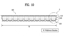
- FIG. 10 is a front view of the distributor unit in accordance with this embodiment of the present invention
- FIG. 11 is an enlarged view of portion "A" of the distributor unit in accordance with this embodiment of the present invention
- FIG. 12 is a plan view illustrating a first refrigerant distribution unit of the distributor unit
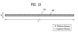
- FIG. 13 is a plan view illustrating a second refrigerant distribution unit of the distributor unit.
- a distributor unit 600 in accordance with another embodiment of the present invention may be formed integrally with the gas-liquid separator unit 100, or be formed separately and then provided under the gas-liquid separator unit 100.
- the distributor unit 600 may include a plurality of first refrigerant distribution units 610 provided with a plurality of first through holes 620 formed in the widthwise direction W of the gas-liquid separator unit 100 to distribute refrigerant in the widthwise direction of the heat transfer pipe 22.
- a plurality of second refrigerant distribution units 630 to re-distribute refrigerant, transmitted from the first refrigerant distribution unit 610, in a lengthwise direction L of the heat transfer pipe 22 may be provided under the plurality of first distribution units 610.
- a plurality of second through holes 640 may be formed on each of the plurality of second refrigerant distribution units 630 in the lengthwise direction L of the gas-liquid separator unit 100 so as to distribute the refrigerant in the lengthwise direction of the heat transfer pipe 22.
- gas-liquid separator unit 100 and the distributor unit 600 may extend so as to correspond to the lengthwise and width of the heat transfer pipe 22 located thereunder.
- the distributor unit 600 may uniformly distribute the refrigerant in the lengthwise direction and widthwise direction of the heat transfer pipe 22.
- the plurality of second refrigerant distribution units 630 located under the plurality of first refrigerant distribution units 610 may perpendicularly cross the plurality of first refrigerant distribution units 610.
- the plurality of second refrigerant distribution unit 630 may include a plurality of refrigerant dropping units 650 guiding the refrigerant introduced through the plurality of second through holes 640 in the lengthwise direction of the heat transfer pipe 22.
- the plurality of refrigerant dropping units 650 are provided in a shape in which the sectional area of the flow surfaces thereof decreases in the flow direction of the refrigerant.
- the plurality of first refrigerant distribution units 610 is installed under the gas-liquid separator unit 100 and extend more in the widthwise direction W than the lengthwise direction L so as to distribute the refrigerant transmitted from the gas-liquid separator unit 100 in the widthwise direction of the gas-liquid separator unit 100.
- the plurality of first refrigerant distribution unit 610 may each have a same width, that is, a same horizontal length, as the gas-liquid separator unit 100.
- the plurality of first refrigerant distribution units 610 separated from each other by a designated interval in the lengthwise direction of the gas-liquid separator unit 100 may be formed on the lower surface of the gas-liquid separator unit 100.
- the plurality of first refrigerant distribution units 610 may each be formed in a polyhedral shape having a designated height, an upper surface of which is opened, so as to receive refrigerant.
- the plurality of first through holes 620 may be formed on a lower surface of each of the plurality of first refrigerant distribution unit 610 so as to transmit the refrigerant to the plurality of second refrigerant distribution units 630.
- the refrigerant dropped from the gas-liquid separator unit 100 is distributed in the widthwise direction by the plurality of first refrigerant distribution units 610 and is dropped to the plurality of second refrigerant distribution units 630 through the plurality of first through holes 620.
- the plurality of second refrigerant distribution units 630 are installed under the plurality of first refrigerant distribution units 610 and may extend more in the lengthwise direction L than the widthwise direction W so as to distribute the refrigerant transmitted from the plurality of first refrigerant distribution units 610 in the lengthwise direction.
- the plurality of second refrigerant distribution units 630 may have the same vertical length as the gas-liquid separator unit 100.
- the plurality of second refrigerant distribution units 630 separated from each other by a designated interval in the widthwise direction of the gas-liquid separator unit 100 may be formed on the lower surfaces of plurality of the first refrigerant distribution units 610.
- the plurality of second refrigerant distribution units 630 may be formed in a polyhedral shape having a designated height, the upper surface of which is opened, so as to receive refrigerant.
- the plurality of second through holes 640 may be formed on the lower surfaces of the plurality of second refrigerant distribution units 640 so as to drop the refrigerant to the heat transfer pipe 22.
- the plurality of first through holes 620 and the plurality of second through holes 640 may be designed such that the numbers and sizes of the plurality of first through holes 620 and the plurality of second through holes 640 are determined according to the flow rate of the refrigerant dropped to the heat transfer pipe 22 and the heights of the refrigerant stored in the plurality of first refrigerant distribution units 610 and the plurality of second refrigerant distribution units 630.
- the plurality of refrigerant dropping units 650 that guide the refrigerant dropped through the plurality of second through holes 640 to the heat transfer pipe 22 in the lengthwise direction of the gas-liquid separator unit 100 may be provided under the plurality of second refrigerant distribution units 630.
- the plurality of refrigerant dropping units 650 may be formed in a shape in which the sectional area of the flow surfaces thereof decreases in the flow direction of the refrigerant.
- the refrigerant distributed in the widthwise direction by the first refrigerant distribution units 610 is distributed in the lengthwise direction by the plurality of second refrigerant distribution units 630, and then transmitted to the plurality of refrigerant dropping units 650 formed in the lengthwise direction through the plurality of second through holes 640 and thus re-distributed in the lengthwise direction and dropped to the heat transfer pipe 22.
- the distributor unit 600 may further include a plurality of third refrigerant distribution units 660 provided on the flow surfaces of the plurality of refrigerant dropping units 650.
- the plurality of third refrigerant distribution unit 660 may include a refrigerant storage unit 670 storing refrigerant dropped from the plurality of second through holes 640 and a plurality of slits 680 formed at the lower portion of the refrigerant storage unit 670.
- the plurality of slits 680 may be provided between the plurality of second refrigerant distribution unit 630 and the plurality of refrigerant dropping unit 650 and guide the refrigerant having passed through the plurality of second through holes 640 to the refrigerant dropping unit 650.
- the plurality of slits 680 may be openings having the same width and thus, the amounts of refrigerant having passed through the plural slits 680 may be uniform in the first direction. Thereby, the amounts of refrigerant distributed to the heat transfer pipe 22 may be uniform in the first direction.
- the plurality of refrigerant dropping units 650 are provided in a shape in which the sectional area of the flow surfaces thereof decreases in the flow direction of the refrigerant, and refrigerant having passed through the plurality of slits 680 drops from the ends of the plurality of refrigerant dropping units 650 having the smallest sectional area to the heat transfer pipe 22.
- refrigerant dropped from the plurality of first refrigerant distribution units 610 is temporarily stored in the plurality of refrigerant storage units 670 of the plurality of second refrigerant distribution units 630. At this time, most of kinetic energy of the refrigerant is lost.
- the refrigerant having lost kinetic energy passes through the plurality of slits 680 formed at the lower portions of the plurality of storage units 670 and then is guided to the ends of the plurality of refrigerant dropping units 650 by surface tension on the flow surfaces of the refrigerant dropping units 650 and gravity.
- the refrigerant drops from the ends of the plurality of refrigerant dropping units 650 having the smallest sectional area of the flow surfaces thereof to the heat transfer pipe 22 by gravity.
- the plurality of slits 680 may be formed on a coaxial line with the ends of the refrigerant dropping units 650 having the smallest sectional area of the flow surfaces thereof.
- the refrigerant having passed through the plurality of slits 680 may rectilinearly flow on the lower flow surfaces of the plurality of refrigerant dropping units 650 and be guided to the ends of the plurality of refrigerant dropping units 650.
- the plurality of slits 680 may be located between two neighboring refrigerant dropping units 650.
- the refrigerant having passed through the plurality of slits 680 may be guided to the ends of the plurality of refrigerant dropping units 650 along the side parts of the flow surfaces of the plurality of refrigerant dropping units 650 which are inclined by a designated angle so that the sectional area of the flow surfaces of the plurality of refrigerant dropping units 650 decreases in the flow direction of the refrigerant.
- the plurality of refrigerant dropping units 650 may be formed in a structure, the sectional area of which decreases in the flow direction of the refrigerant and which has a sharpened end, and a plurality of these refrigerant dropping units 650 may be connected.
- the plurality of refrigerant dropping units 650 may be formed in a saw-toothed shape.
- the sharpened ends of the refrigerant dropping units 650 may be located corresponding to the heat transfer pipe 22 to which the refrigerant will be dropped.
- a number of the sharpened refrigerant dropping units 650 may be designed in consideration of a pitch by which dry spots are not generated in the heat transfer pipe 22.
- These structured refrigerant dropping units 650 may uniformly distribute the refrigerant to the heat transfer pipe 22 and drop the refrigerant correctly to the heat transfer pipe 22, and thus, may reduce an amount of liquid refrigerant which does not contact the heat transfer pipe 22
- an evaporator in accordance with one embodiment of the present invention uniformly distributes refrigerant to a heat transfer pipe and thus improves heat exchange efficiency.
- the evaporator in accordance with the embodiment of the present invention may uniformly distribute refrigerant to the heat transfer pipe in the lengthwise direction as well as in the widthwise direction.
- the evaporator in accordance with the embodiment of the present invention lowers dynamic pressures of gases refrigerant and liquid refrigerant introduced into the evaporator, and thus, may effectively control two-phase flow.
- the evaporator in accordance with the embodiment of the present invention effectively separates gases refrigerant and liquid refrigerant introduced into the evaporator from each other, and thus, may cause the liquid refrigerant alone to be introduced into the distributor unit and then uniformly distributed.
- the evaporator in accordance with the embodiment of the present invention may prevent the liquid refrigerant from being introduced into a compressor by a gas-liquid separator unit provided with an eliminator.
- the evaporator in accordance with the embodiment of the present invention may distribute the refrigerant correctly to a position of a heat transfer pipe to which the refrigerant is to be dropped and thus increase heat exchange efficiency.
Landscapes
- Engineering & Computer Science (AREA)
- Physics & Mathematics (AREA)
- Thermal Sciences (AREA)
- Mechanical Engineering (AREA)
- General Engineering & Computer Science (AREA)
- Heat-Exchange Devices With Radiators And Conduit Assemblies (AREA)
Description
- The present invention relates to an evaporator having a distributor unit which may uniformly distribute refrigerant to a heat transfer pipe.
- In general, a turbo refrigerating machine is an apparatus performing heat exchange between chilled water and condensed water using refrigerant and includes a compressor, an evaporator, a condenser, and an expansion valve.
- The evaporator and the condenser may have a shell-in-tube structure, chilled water and condensed water respectively flow in the tubes of the evaporator and the condenser, and refrigerant may be received in the shells of the evaporator and the condenser.
- Further, chilled water is introduced into and discharged from the evaporator, heat exchange between the refrigerant and the chilled water is performed in the evaporator, and the chilled water is cooled during a process of passing through the evaporator.
- If the evaporator is a falling film evaporator, a distributor unit to uniformly distribute refrigerant introduced into the evaporator to a heat transfer pipe in which chilled water flows may be provided.
- In order to uniformly distribute the refrigerant to the heat transfer pipe through the distributor unit, it is important to effectively control two-phase flow between liquid refrigerant and gaseous refrigerant introduced into the evaporator.
- However, since the moving velocity of the refrigerant introduced into the evaporator is high, it may be difficult to uniformly distribute the refrigerant along the heat transfer pipe.
- Further, if a refrigerant mixture of gaseous refrigerant and liquid refrigerant is introduced into the evaporator and separation of the gaseous refrigerant and the liquid refrigerant from the refrigerant mixture is not efficiently carried out, the refrigerant may not be uniformly distributed due to a dynamic pressure difference of the two phase refrigerant and non-uniform dynamic pressure.
- In the conventional distributor unit, the introduced refrigerant flows only to corners and thus, the refrigerant may not be uniformly distributed to the heat transfer pipe or the distributor unit is manufactured in a complex shape to achieve uniform refrigerant flow.
- Therefore, a distributor unit, which may effectively separate liquid refrigerant and gaseous refrigerant from refrigerant, introduced into an evaporator, and lower dynamic pressures of the liquid refrigerant and the gaseous refrigerant so as to easily control two-phase flow, has been required.
- Further, a distributor unit, which may uniformly distribute liquid refrigerant separated at the inside of an evaporator to a heat transfer pipe provided in the evaporator, has been required.
-
US 2009/178790 A1 discloses an evaporator for use in a vapor compression system. The evaporator may include an enclosure that covers a substantial portion of a tube bundle in the evaporator. The enclosure substantially prevents refrigerant vapor, generated as a result of the heat transfer with the tube bundle, from flowing laterally between tubes of the tube bundle. Various configurations of a distributor for distributing refrigerant to at least a portion of a tube bundle in the evaporator provides increased performance of the evaporator.US 6 868 695 B1 discloses a falling film evaporator includes a flow distributor for uniformly distributing a two-phase refrigerant mixture across a tube bundle.WO 00/55552 A1 - An object of the present invention is to provide an evaporator which may uniformly distribute refrigerant to a heat transfer pipe to improve heat exchange efficiency.
- Another object of the present invention is to provide an evaporator having a distributor unit which may lower dynamic pressures of gaseous refrigerant and liquid refrigerant introduced into an evaporator to easily control two-phase flow.
- Another object of the present invention is to provide an evaporator having a distributor unit which may effectively separate gaseous refrigerant and liquid refrigerant.
- Yet another object of the present invention is to provide an evaporator having a distributor unit with which a gas-liquid separator unit supplying liquid refrigerant alone to the distributor unit to uniformly distribute the refrigerant is integrated.
- These objects are achieved with the features of the claims.
- To achieve these objects and other advantages and in accordance with the purpose of the invention, as embodied and broadly described herein, the invention provides an evaporator as defined in
independent claim 1. - The distributor unit may comprise a first refrigerant distribution unit provided with a plurality of through holes formed in a first direction.
- The plurality of refrigerant dropping units may guide liquid refrigerant, dropped from the first refrigerant distribution unit through the plurality of through holes, to a heat transfer pipe and having a sectional area of flow surfaces thereof which decreases in the flow direction of the liquid refrigerant.
- The distributor unit may further include a plurality of second refrigerant distribution units provided on the flow surfaces of the plurality of refrigerant dropping units, each of the plurality of second refrigerant distribution units including a refrigerant storage unit temporarily storing the liquid refrigerant dropped from the plurality of through holes and a plurality of slits formed at the lower portion of the refrigerant storage unit.
- The plurality of slits may be provided between the first refrigerant distribution unit and the plurality of refrigerant dropping units and adapted to guide the liquid refrigerant having passed through the plurality of through holes to the plurality of refrigerant dropping units.
- Each of the plurality of slits may be aligned with the end having the smallest sectional area of the flow surfaces of a corresponding one of the plurality of refrigerant dropping units, the axis of alignment lying in a vertical plane.
- Each of the plurality of slits may be located between two neighboring refrigerant dropping units and guides flow of the liquid refrigerant along the side parts of the plurality of the refrigerant dropping units which are inclined by a designated angle so that the sectional area of the flow surfaces of the plurality of refrigerant dropping units decreases in the flow direction of the liquid refrigerant.
- The plurality of refrigerant dropping units may be formed in a saw-toothed shape.
- Each of the plurality of refrigerant dropping units may include first areas in which the liquid refrigerant dropped from the plurality of through holes of the first refrigerant distribution unit flows and second areas which extend downwards from the first areas, the sectional area of flow surfaces of the second areas decreasing in the flow direction of the liquid refrigerant so as to drop the liquid refrigerant to the heat transfer pipe.
- The first areas may form curved surfaces and the second areas may form planar surfaces.
- The first area and the second area are connected at a designated angle and a boundary part between the first area and the second area forms a curved surface.
- The evaporator may further comprise a refrigerant storage unit storing the liquid refrigerant dropped from the plurality of through holes, and a plurality of slits formed at the lower portion of the refrigerant storage unit_is provided in the second area.
- Each of the plurality of refrigerant dropping units may be located at an edge of a corresponding one of the plurality of through holes.
- The refrigerant dropping units each may have a pointed tip.
- Part of the liquid refrigerant distributed by the distributor unit may be carried to the bottom of the shell and a part of the heat transfer pipe may be submerged in a pool formed at the bottom of the shell.
- The eliminator may be located above the gaseous refrigerant outlet.
- In another aspect of the present invention, a distributor unit includes a first member provided with a plurality of through holes formed in a first direction and second members including a plurality of refrigerant dropping units.
- The plurality of refrigerant dropping units may be connected to the first member, guide refrigerant introduced through the plurality of through holes to a heat transfer pipe, and have the sectional area of flow surfaces thereof which decreases in the flow direction of the refrigerant.
- Further, the second member may include first areas in which the refrigerant dropped from the plurality of through holes flows and second areas which extend from the first areas in the flow direction of the refrigerant and in which the plurality of refrigerant dropping units is provided.
- The distributor unit may further include third members, each of which includes a refrigerant storage unit storing the refrigerant dropped from the plurality of through holes and a plurality of slits formed at the lower portion of the refrigerant storage unit.
- In another aspect of the present invention, a distributor unit includes first refrigerant distribution units distributing refrigerant in the widthwise direction and second refrigerant distribution units receiving the refrigerant transmitted from the first refrigerant distribution units and distributing the refrigerant in the lengthwise direction.
- The first refrigerant distribution units may be provided with a plurality of first through holes formed in a widthwise direction so as to distribute refrigerant in the widthwise direction and the second refrigerant distribution units may be provided with a plurality of second through holes formed in a lengthwise direction so as to distribute the refrigerant in the lengthwise direction.
- The plurality of refrigerant dropping units may guide the refrigerant, introduced from the second refrigerant distribution units through the plurality of second through holes, to a heat transfer pipe in the lengthwise direction and having the sectional area of flow surfaces thereof which decreases in the flow direction of the refrigerant.
- The evaporator may be a hybrid falling film evaporator in which a part of the liquid refrigerant distributed by the distributor unit is carried to the bottom of the shell and a part of the heat transfer pipe is submerged in a pool formed at the bottom of the shell.
- It is to be understood that both the foregoing general description and the following detailed description of the present invention are exemplary and explanatory and are intended to provide further explanation of the invention as claimed.
- The accompanying drawings, which are included to provide a further understanding of the invention and are incorporated in and constitute a part of this application, illustrate embodiment(s) of the invention and together with the description serve to explain the principle of the invention. In the drawings:
-
FIG. 1 is a conceptual view illustrating a turbo refrigerating machine in accordance with the present invention; -
FIG. 2 is a conceptual view illustrating the inside of an evaporator in accordance with the present invention; -
FIG. 3 is a perspective view illustrating a gas-liquid separator unit and a distributor unit of the evaporator in accordance with the present invention; -
FIG. 4 is a longitudinal-sectional view of the gas-liquid separator unit and the distributor unit of the evaporator in accordance with the present invention; -
FIG. 5 is an exploded perspective view of the gas-liquid separator unit and the distributor unit of the evaporator in accordance with the present invention; -
FIGs. 6 and7 are views of a distributor unit in accordance with one embodiment of the present invention; -
FIG. 8 is an enlarged front view of the distributor unit in accordance with the embodiment of the present invention; -
FIG. 9 is a perspective view of the distributor unit illustrating a modification of second members in accordance with the embodiment of the present invention; -
FIG. 10 is a front view of a distributor unit in accordance with another embodiment of the present invention; -
FIG. 11 is an enlarged view of portion "A" of the distributor unit in accordance with the embodiment of the present invention; -
FIG. 12 is a plan view illustrating a first refrigerant distribution unit of the distributor unit in accordance with the embodiment of the present invention; and -
FIG. 13 is a plan view illustrating a second refrigerant distribution unit of the distributor unit in accordance with the embodiment of the present invention. - Hereinafter, an evaporator in accordance with one embodiment of the present invention will be described with reference to the accompanying drawings. Reference will now be made in detail to the preferred embodiments of the present invention, examples of which are illustrated in the accompanying drawings.
- Further, the same or similar elements are denoted by the same or similar reference numerals even though they are depicted in different drawings and a detailed description thereof will thus be omitted because it is considered to be unnecessary. In the drawings, the sizes or shapes of elements may be exaggerated or reduced for clarity and convenience of description.
- Further, it will be understood that, although the terms first, second, etc. may be used herein to describe various elements, these elements should not be limited by these terms.
- Hereinafter, an evaporator in accordance with one embodiment of the present invention will be described in detail with reference to the accompanying drawings.
-
FIG. 1 is a conceptual view illustrating a turbo refrigerating machine. - With reference to
FIG. 1 , aturbo refrigerating machine 1 to which an evaporator in accordance with the present invention is applied may include acompressor 10 to compress refrigerant, acondenser 30, anexpansion valve 40, and anevaporator 20. - In more detail, the
turbo refrigerating machine 1 includes thecompressor 10 including animpeller 11 to compress refrigerant and thecondenser 30 for heat exchange between the refrigerant flowing from thecompressor 10 and condensed water. - Further, the
turbo refrigerating machine 1 may include theevaporator 20 for heat exchange between the refrigerant discharged from thecondenser 30 and chilled water and theexpansion valve 40 provided between thecondenser 20 and theevaporator 20. - The
compressor 10 may include a one-stage or two-stage compression unit. Thecompressor 10 may include theimpeller 11 rotated by driving force of a drive motor to compress the refrigerant. - The
compressor 10 may include a shroud in which theimpeller 11 is accommodated and a variable diffuser converting kinetic energy of fluid discharged due to rotation of theimpeller 11 into pressure energy. -
FIG. 1 illustrates thecompressor 10 including a one-stage compression unit. - In accordance with one embodiment, the
evaporator 20 and thecondenser 30 may have a shell-in-tube structure, chilled water and condensed water respective flow in the tubes of theevaporator 20 and thecondenser 30, and refrigerant may be received to designated heights in the shells of theevaporator 20 and thecondenser 30. - Here, chilled water is introduced into and discharged from the
evaporator 20, and heat exchange between refrigerant and the chilled water is carried out within theevaporator 20 so that the chilled water introduced into theevaporator 20 may be cooled while passing through theevaporator 20. - Further, condensed water is introduced into and discharged from the
condenser 30, heat exchange between refrigerant and the condensed water is carried out within thecondenser 30 so that the condensed water may be heated while passing through thecondenser 30. - As described above, the
compressor 10 may include a two-stage compression unit. In this case, thecompressor 10 may be a multi-stage compressor having a plurality of stages. - In accordance with one embodiment, if the
compressor 10 includes a two-stage compression unit, theturbo refrigerating machine 1 may further include an economizer to separate liquid refrigerant and gaseous refrigerant from refrigerant discharged from thecondenser 30 and to discharge the separated gaseous refrigerant to thecompressor 10. - Further, the
turbo refrigerating machine 1 may include a first expansion valve provided between thecondenser 30 and the economizer and a second expansion valve provided between the economizer and theevaporator 20. - If the
compressor 10 includes the two-stage compression unit, as described above, in accordance with one embodiment, thecompressor 10 includes a low-pressure compression unit and a high-pressure compression unit. - A one-stage impeller is provided at the low-pressure compression unit and a two-stage impeller is provided at the high-pressure compression unit. Here, the refrigerant discharged from the
evaporator 20 may be introduced into the low-pressure compression unit and the gaseous refrigerant separated by the economizer may be introduced into the high-pressure compression unit. - Consequently, since both the gaseous refrigerant separated by the economizer and the refrigerant compressed by the low-pressure compression unit are compressed in the high-pressure compression unit, a compression load applied to the
compressor 10 is reduced. As the compression load applied to thecompressor 10 is reduced, the operating range of thecompressor 10 may be increased. -
FIG. 2 is a conceptual view illustrating the inside of the evaporator in accordance with the present invention. - Although
FIG. 2 exemplarily illustrates a falling film evaporator, a distributor unit and an evaporator having the same in accordance with the present invention are not limited thereto. - A refrigerant mixture X introduced into the
evaporator 20 in accordance with the present invention may be uniformly distributed to aheat transfer pipe 22 in which chilled water flows through adistributor unit 200. - In order to uniformly distribute the refrigerant mixture X to the
heat transfer pipe 22 through thedistributer unit 200, it is important to control two-phase flow of the refrigerant mixture X of liquid refrigerant L and gaseous refrigerant G introduced into theevaporator 20. - Since the dynamic pressure of the refrigerant mixture X of liquid refrigerant L and gaseous refrigerant G flowing in the
distributer unit 200 is not uniform, the refrigerant mixture X may not be uniformly distributed to theheat transfer pipe 22 by thedistributer unit 200. - Further, the velocity of the refrigerant mixture X introduced into the
evaporator 20 may be high and thus, the refrigerant mixture X may not be uniformly distributed by thedistributor unit 200. - As described above, non-uniform refrigerant distribution may form dry spots in the
heat transfer pipe 22 and such local dry spots may lower the overall heat exchange performance of the falling film evaporator. - Therefore, the refrigerant mixture X flowing in the
distributor unit 200 needs to be effectively separated into gaseous refrigerant G and liquid refrigerant L and requires uniform maintenance of dynamic pressure of the refrigerant flowing in thedistributor unit 200. - The
evaporator 20 in accordance with one embodiment of the present invention may be a falling film evaporator and have a shell-in-tube structure. - Further, the
heat transfer pipe 22 in which chilled water flows, a gas-liquid separator unit 100 in which the refrigerant introduced into theevaporator 100 flows, and thedistributor unit 200 are provided within ashell 21. -
FIG. 3 is a perspective view illustrating the gas-liquid separator unit and the distributor unit of the evaporator in accordance with the present invention. - Hereinafter, the gas-
liquid separator unit 100 and thedistributor unit 200 which are integrated with each other in theshell 21 will be described, as exemplarily shown inFIG. 3 , but embodiments of the present invention are not limited thereto. - Further, although the
evaporator 20 including the integrated gas-liquid separator unit 100 anddistributor 200 which is applied to theturbo refrigerating machine 1 will be exemplarily illustrated, embodiments of the present invention are not limited thereto and may be applied to various air conditioners. - Hereinafter, the evaporator and the gas-liquid separator unit and the distributor unit forming the evaporator in accordance with the present invention will be described in detail with reference to
FIGs. 2 to 5 . -
FIG. 3 is a perspective view illustrating the gas-liquid separator unit and the distributor unit forming the evaporator in accordance with the present invention andFIGs. 4 and5 are longitudinal-sectional and exploded perspective views of the gas-liquid separator unit and the distributor, respectively. - The
evaporator 20 in accordance with the present invention includes theshell 21 forming the external appearance of theevaporator 20 and the gas-liquid separator unit 100 separating gases refrigerant and liquid refrigerant from the refrigerant mixture introduced into arefrigerant inlet 110 in theevaporator 20. - Further, the
evaporator 20 includes thedistributor unit 200 formed under the gas-liquid separator unit 100 and uniformly distributing the liquid refrigerant to theheat transfer pipe 22 and theheat transfer pipe 22 in which chilled water to exchange heat with the liquid refrigerant distributed by thedistributor unit 200 flows. - The
evaporator 20 in accordance with the present invention may be a hybrid falling film evaporator in which a part of the liquid refrigerant distributed by thedistributor unit 200 is carried to the bottom of theshell 21 and a part of theheat transfer pipe 22 is submerged in a pool in which the liquid refrigerant carried to the bottom of theshell 21 is stored to a designated height. - The
evaporator 20 in accordance with the present invention includes the gas-liquid separator unit 100 and thedistributor unit 200 which are integrated with each other in theshell 21. - The integrated gas-
liquid separator unit 100 and thedistributor 200 may be advantageous in that the gas-liquid separator unit 100 separates the gases refrigerant and the liquid refrigerant introduced into theevaporator 20 in a mixed state and then, thedistributor unit 200 immediately distributes the liquid refrigerant to theheat transfer pipe 22. - The integrated gas-
liquid separator unit 100 and thedistributor 200 may extend corresponding to the length and width of theheat transfer pipe 22 located therebelow. - Thereby, the
distributor unit 200 may uniformly distribute the liquid refrigerant in the lengthwise direction and the widthwise direction of theheat transfer pipe 22. - The gas-
liquid separator unit 100 includes ahousing 120 including therefrigerant inlet 110 and a plurality ofporous plates 130 separating gases refrigerant and liquid refrigerant from a refrigerant mixture introduced through therefrigerant inlet 110. - The
housing 120 includes a gasesrefrigerant outlet 140 through which the separated gases refrigerant is discharged from thehousing 120 and a liquidrefrigerant outlet 150 through which the separated liquid refrigerant is discharged from thehousing 120. Here, the liquidrefrigerant outlet 150 may include a plurality of through holes formed through the lower surface of thehousing 120. - The gases
refrigerant outlet 140 is located at one end of thehousing 120 opposite therefrigerant inlet 110 located at the other end of thehousing 120 in the lengthwise direction. The gases refrigerant discharged through the gasesrefrigerant outlet 140 may be introduced into thecompressor 110. - An
eliminator 160 is provided above the gasesrefrigerant outlet 140 and may thus prevent the liquid refrigerant from being introduced into thecompressor 10. Theeliminator 160 may be formed in a shape in which plural metal nets are stacked to perform a function of filtering the liquid refrigerant discharged together with the gases refrigerant. - The
eliminator 160 may extend toward therefrigerant inlet 110 to a designated length in the lengthwise direction from one end of thehousing 120, opposite therefrigerant inlet 110 located at the other end of thehousing 120 in the lengthwise direction. Theeliminator 160 may be designed such that the size of theeliminator 160 corresponds to dryness and flow rate of the refrigerant. - A plurality of plurality of
porous plates 130, each of which is provided with a plurality of holes to pass fluid, is provided. The plurality ofporous plates 130 is separated from each other by a designated interval in the lengthwise direction of thehousing 120 and be provided within thehousing 120. - The plurality of
porous plates 130 may perform a function of controlling cyclic change of dynamic pressures due to a density difference between gases refrigerant and liquid refrigerant introduced into the gas-liquid separator unit 100. In more detail, the plurality ofporous plates 130 lowers dynamic pressures of gases refrigerant and liquid refrigerant and thus facilitates control of two-phase refrigerant flow. - That is, when gases refrigerant and liquid refrigerant having different velocities introduced into the gas-
liquid separator unit 100 through therefrigerant inlet 110 collide with the plurality ofporous plates 130, the velocities thereof may be lowered and dynamic pressures thereof may be changed to a regular value. - The gas-
liquid separator unit 110 including the plurality ofporous plates 130 may control two-phase flow through the plurality ofporous plates 130, even if refrigerant flow becomes unstable due to change of a driving condition, and thus uniformly distribute refrigerant. - Further, when the refrigerant mixture of gases refrigerant and liquid refrigerant introduced into the
refrigerant inlet 110 collides with the plurality ofporous plates 130, the velocity thereof may be lowered and thus, stable gas-liquid separation of the refrigerant mixture into the gaseous refrigerant and the liquid refrigerant may be achieved. - The number of the plurality of
porous plates 130 provided in thehousing 120, the installation positions of the plurality ofporous plates 130, and porosity of the plurality ofporous plates 130 may be main factors determining velocity control of two-phase refrigerant and a stable gas-liquid separation area. - As exemplarily shown in
FIG. 5 , thedistributor unit 200 may include a plurality of firstrefrigerant distribution unit 210 provided with a plurality of first throughholes 220 formed in the widthwise direction W to distribute refrigerant in the widthwise direction W. - Further, the
distributor unit 200 may include a secondrefrigerant distribution unit 230 provided with second throughholes 240 formed in the lengthwise direction L to distribute refrigerant in the lengthwise direction L. - The second
refrigerant distribution unit 230 may re-distribute refrigerant in the lengthwise direction through the second throughholes 240 and then drop the refrigerant to theheat transfer pipe 22. Further, in order to drop the refrigerant to theheat transfer pipe 22, the secondrefrigerant distribution unit 230 may include a plurality of refrigerant droppingunits 250 having the sectional area of flow surfaces thereof which decreases in the flow direction of the refrigerant. - In order to more uniformly distribute the refrigerant, each of the
refrigerant dropping unit 250 may include a refrigerant storage unit storing the refrigerant dropped from the second throughholes 240 and a plurality of slits formed at the lower portion the refrigerant storage unit. - Hereinafter, the distributor unit will be described in detail with reference to the accompanying drawings.
-
FIGs. 6 and7 are views of a distributor unit in accordance with one embodiment of the present invention. - A
distributor unit 300 in accordance with this embodiment of the present invention may be formed integrally with the gas-liquid separator unit 100 or be formed separately from the gas-liquid separator unit 100 and provided under the gas-liquid separator unit 100. - The
distributor unit 300 may include a plurality of firstrefrigerant distribution units 310 provided with a plurality of throughholes 320 formed in a first direction (hereinafter, referred to as "the lengthwise direction"). - Further, the
distributor unit 300 may includes a plurality of refrigerant droppingunits 330 guiding refrigerant dropped through the throughholes 320 to theheat transfer pipe 22 and having the sectional area of flow surfaces thereof which decreases in the flow direction of the refrigerant. - The plurality of refrigerant dropping
units 330 may be located on the lower surface of the firstrefrigerant distribution unit 310 and be combined with the firstrefrigerant distribution unit 310 in a mechanical combination manner, such as spot welding or bolt fastening. - The plurality of
refrigerant dropping unit 330 may includefirst areas 332 in which the refrigerant dropped from the throughholes 320 flows andsecond areas 334, the sectional area of flow surfaces of which decreases in the flow direction of the refrigerant so as to drop the refrigerant having flown on thefirst areas 332 to theheat transfer pipe 22. - The
first areas 332 may form curved surfaces and thesecond areas 334 may form planar surfaces. Thefirst area 332 and thesecond area 334 may be connected at a designated angle and a boundary part at which thefirst area 332 and thesecond area 334 are connected may form a curved surface. - The
second areas 334 may be formed in the same direction as the direction of gravity so that refrigerant may drop vertically from the plurality of refrigerant droppingunits 330. That is, thefirst area 332 and thesecond area 334 may be connected at an angle of 90 degrees or more. - The
distributor unit 300 may further include a plurality of secondrefrigerant distribution units 340 guiding uniform dropping of the refrigerant, dropped through the throughholes 320 of the firstrefrigerant distribution unit 310, to theheat transfer pipe 22. - The second
refrigerant distribution unit 340 is provided on the flow surface of the plurality ofrefrigerant dropping unit 330 and may include arefrigerant storage unit 350 storing refrigerant dropped from the throughholes 320 and then flowing along the flow surface of the plurality ofrefrigerant dropping unit 330. - Further, the second
refrigerant distribution unit 340 may be provided with a plurality of slits formed at the lower portion of therefrigerant storage unit 350 and guide the refrigerant stored in therefrigerant storage unit 350 to the plurality ofrefrigerant dropping unit 330. - The plurality of second
refrigerant distribution units 340 may extend in the first direction and the plurality ofslits 360 may be separated from each other by a designated interval in the first direction. - The plurality of
slits 360 may be openings having the same width and thus, the amounts of refrigerant having passed through theplural slits 360 may be uniform in the first direction. Thereby, the amounts of refrigerant distributed to theheat transfer pipe 22 may be uniform in the first direction. - The plurality of refrigerant dropping
units 330 are provided in a shape in which the sectional area of the flow surfaces thereof decreases in the flow direction of the refrigerant, and refrigerant having passed through the plurality ofslits 360 drops from the ends of the plurality of refrigerant droppingunits 330 having the smallest sectional area to theheat transfer pipe 22. - As described above, refrigerant dropped from the first
refrigerant distribution unit 310 is temporarily stored in therefrigerant storage units 350 of the plurality of secondrefrigerant distribution units 340. At this time, most of kinetic energy of the refrigerant is lost. - The refrigerant losing kinetic energy passes through the plurality of
slits 360 formed at the lower ends of thestorage units 350 and then is guided to the ends of the plurality of refrigerant droppingunits 330 by surface tension on the flow surfaces of the plurality of refrigerant droppingunits 330 and gravity. - The refrigerant drops from the ends of the plurality of refrigerant dropping
units 330 having the smallest sectional area of the flow surfaces thereof to theheat transfer pipe 22 by gravity. - The second
refrigerant distribution unit 340 may be provided in thesecond area 334 of the plurality ofrefrigerant dropping unit 330. - The reason for this is that the refrigerant rapidly moves from the boundary part, in which the
first area 332 and thesecond area 334 are connected, to thesecond area 334 having a greater gradient than thefirst area 332 after flowing in thefirst area 332 and is thus easily stored in therefrigerant storage unit 350. - The
refrigerant storage unit 350 may have a greater height than the start point of the curved surface of the boundary part, in which thefirst area 332 and thesecond area 334 are connected. That is, therefrigerant storage unit 350 may extend from the boundary part to a designated height toward the firstrefrigerant distribution unit 310. This may serve to form a space storing the refrigerant in therefrigerant storage unit 350. - The
refrigerant storage unit 350 may have a hollow cylindrical or polyhedral shape, the upper surface of which is opened, so as to easily store a liquid flowing in the downward direction. - Here, the downward flow direction of the liquid may be the same as the direction of gravity.
- One surface of the
refrigerant storage unit 350 may be combined with thesecond areas 334 so as to store the refrigerant flowing from thefirst areas 332 and introduced into thesecond areas 334 of the plurality of refrigerant droppingunits 330. - The plurality of
slits 360 of the secondrefrigerant distribution member 340 may be formed at the lower portion of therefrigerant storage unit 350. An opening formed at one side of each of the plurality ofslits 360 may contact thesecond area 334 of the plurality ofrefrigerant dropping unit 330. - The plurality of
slits 360 may be through holes formed adjacent to the refrigerant droppingunits 330. - Here, the plurality of
slits 360 may be formed on a coaxial line with the ends of the plurality of refrigerant droppingunits 330 having the smallest sectional area of the flow surfaces thereof. The refrigerant having passed through the plurality ofslits 360 may rectilinearly flow on the lower flow surfaces of the plurality of refrigerant droppingunits 330 and be guided to the ends of the plurality of refrigerant droppingunits 330. - Otherwise, the plurality of
slits 360 may be located between two neighboring refrigerant droppingunits 330. Here, the refrigerant having passed through the plurality ofslits 360 may be guided to the ends of the plurality of refrigerant droppingunits 330 along the side parts of the flow surfaces of the plurality of refrigerant droppingunits 330 having the sectional area of the flow surfaces thereof which decreases in the flow direction of the refrigerant. The side parts of the flow surfaces may be parts inclined by a predetermined angle so that the sectional area of the flow surfaces of the plurality of refrigerant droppingunits 330 decreases in the flow direction of the refrigerant. - The plurality of refrigerant dropping
units 330 may be formed in a structure, the sectional area of which decreases in the flow direction of the refrigerant and which has a sharpened end, and a plurality of these refrigerant droppingunits 330 may be connected. For example, the plurality of refrigerant droppingunits 330 is formed in a saw-toothed shape. - The sharpened ends of the plurality of refrigerant dropping
units 330 may be located corresponding to theheat transfer pipe 22 to which the refrigerant will be dropped. - Further, a number of the sharpened
refrigerant dropping units 330 may be designed in consideration of a pitch by which dry spots are not generated in theheat transfer pipe 22. - The plurality of refrigerant dropping
units 330 having the above structure drop the refrigerant correctly to theheat transfer pipe 22 and thus, may reduce an amount of liquid refrigerant which does not contact theheat transfer pipe 22 and is eliminated. -
FIG. 8 is an enlarged front view of the distributor unit. With reference toFIG. 8 , the structure of a distributor unit in accordance with one embodiment of the present invention will be described in detail. - A
distributor unit 400 may include afirst member 410 provided with a plurality of throughholes 420 formed to extend in a first direction. Here, the first direction may be the same as a lengthwise direction of theheat transfer pipe 22 provided within theevaporator 20. - Further, the
distributor unit 400 may include plurality ofsecond members 430 including a plurality of refrigerant droppingunits 460 connected to thefirst member 410, to guide refrigerant introduced through the plurality of throughholes 420 to theheat transfer pipe 22, and having a sectional area of flow surfaces thereof which decreases in a flow direction of the refrigerant. - The plurality of
second members 430 may be located under the lower surface of thefirst member 410 and be combined with thefirst member 410 in a mechanical combination manner, such as spot welding or bolt fastening. - The plurality of
second member 430 may includefirst areas 440 in which the refrigerant dropped from the plurality of throughholes 420 flows andsecond areas 450 that extend from thefirst areas 440 in the flow direction of the refrigerant. A plurality of refrigerant droppingunits 460 is provided in thesecond areas 450. - The
first areas 440 may form curved surfaces and thesecond areas 450 may form planar surfaces. Thefirst area 440 and thesecond area 450 may be connected at a predetermined angle and a boundary part at which thefirst area 440 and thesecond area 450 are connected may form a curved surface. - The
second areas 450 may be formed to extend in a same direction as the direction of gravity so that refrigerant may drop vertically from the plurality of refrigerant droppingunits 460. That is, thefirst area 440 and thesecond area 450 may be connected at an angle of about 90 degrees or more. - The
distributor unit 400 may further include a plurality ofthird members 470, each of which includes arefrigerant storage unit 480 storing the refrigerant dropped from the plurality of throughholes 420 and flowing in thefirst area 440 and a plurality ofslits 490 formed at a lower portion of therefrigerant storage unit 480. - The plurality of
third members 470 may extend to a same length as the plurality ofsecond members 430, that is, in the first direction. - Otherwise, a plurality of
third members 470 may be formed on thesecond member 430 in the first direction. - The plurality of
third members 470 may be located in thesecond areas 450 of thesecond members 430. - Particularly, the
refrigerant storage unit 480 may be formed at the end point of the boundary part at which thefirst area 440 and thesecond area 450 of thesecond member 430 are connected via a curved surface. - The reason for this is that the refrigerant rapidly moves from the boundary part to the
second area 450 having a greater gradient than thefirst area 440 after flowing in thefirst area 440, and thus, is easily stored in therefrigerant storage unit 480. - Each
refrigerant storage unit 480 may have a greater height than the start point of the boundary part. That is, eachrefrigerant storage unit 480 may extend from the boundary part to a designated height toward thefirst member 410. This may serve to form a space that stores the refrigerant in therefrigerant storage unit 480. - Each
refrigerant storage unit 480 may have a hollow cylindrical or polyhedral shape, the upper surface of which is opened, so as to easily store a liquid flowing in the downward direction. - A downward flow direction of the liquid may be substantially the same as the direction of gravity.
- One surface of each
refrigerant storage unit 480 may be combined with a respectivesecond area 450 so as to store the refrigerant flowing from a respectivesecond member 430. - The plurality of
slits 490 of eachthird member 470 may be formed at the lower portion of therefrigerant storage unit 480. An opening formed at one side of each of theslits 490 may contact thesecond area 450 of the respectivesecond member 430. - The plurality of
slits 490 may be through holes formed adjacent to the refrigerant droppingunits 460. - The plurality of
slits 490 of thethird member 470 may be formed on a coaxial line with the ends of the plurality of refrigerant droppingunits 460 having the smallest sectional area of the flow surfaces thereof. - Otherwise, the plurality of
slits 490 may be located between neighboring refrigerant droppingunits 460 so that the refrigerant flows along the side parts of the flow surfaces of the plurality of refrigerant droppingunits 460 having the sectional area of the flow surfaces thereof which decreases in the flow direction of the refrigerant. The side parts of the flow surfaces may be inclined parts having a predetermined angle so that the sectional area of the flow surfaces of the plurality of refrigerant droppingunits 460 decreases in the flow direction of the refrigerant. - The plurality of
second members 430 may be formed in a shape which is symmetrical with respect to a second direction perpendicular to the first direction as a central line. Here, the second direction may be the same as the direction of gravity. -
FIG. 9 is a perspective view illustrating a modification of second members of a distributor unit in accordance with one embodiment of the present invention. - As exemplarily shown in
FIG. 9 , adistributor unit 500 may be configured such that afirst member 510 provided with first through holes formed in the first direction andsecond members 530, the sectional area of flow surfaces thereof decreases in the flow direction of the refrigerant are formed integrally. Here, the first direction may be the same as the lengthwise direction of theheat transfer pipe 22 provided within theevaporator 20. - The
second members 530 may be formed by partially cutting the lower surface of thefirst member 510 to form the throughholes 520 and then bending the cut parts. - Otherwise, the plurality of
second members 530 may be formed separately from thefirst member 510 and then combined with the lower surfaces of the plurality of throughholes 520. Here, the plurality of throughholes 520 of thefirst member 510 and thesecond members 530 may be formed in different shapes. - Hereinafter, a distributor unit in accordance with another embodiment of the present invention will be described with reference to
FIGs. 10 to 13 . -
FIG. 10 is a front view of the distributor unit in accordance with this embodiment of the present invention,FIG. 11 is an enlarged view of portion "A" of the distributor unit in accordance with this embodiment of the present invention,FIG. 12 is a plan view illustrating a first refrigerant distribution unit of the distributor unit, andFIG. 13 is a plan view illustrating a second refrigerant distribution unit of the distributor unit. - A
distributor unit 600 in accordance with another embodiment of the present invention may be formed integrally with the gas-liquid separator unit 100, or be formed separately and then provided under the gas-liquid separator unit 100. - The
distributor unit 600 may include a plurality of firstrefrigerant distribution units 610 provided with a plurality of first throughholes 620 formed in the widthwise direction W of the gas-liquid separator unit 100 to distribute refrigerant in the widthwise direction of theheat transfer pipe 22. - Further, a plurality of second
refrigerant distribution units 630 to re-distribute refrigerant, transmitted from the firstrefrigerant distribution unit 610, in a lengthwise direction L of theheat transfer pipe 22 may be provided under the plurality offirst distribution units 610. - A plurality of second through
holes 640 may be formed on each of the plurality of secondrefrigerant distribution units 630 in the lengthwise direction L of the gas-liquid separator unit 100 so as to distribute the refrigerant in the lengthwise direction of theheat transfer pipe 22. - Here, the gas-
liquid separator unit 100 and thedistributor unit 600 may extend so as to correspond to the lengthwise and width of theheat transfer pipe 22 located thereunder. - Thereby, the
distributor unit 600 may uniformly distribute the refrigerant in the lengthwise direction and widthwise direction of theheat transfer pipe 22. - The plurality of second
refrigerant distribution units 630 located under the plurality of firstrefrigerant distribution units 610 may perpendicularly cross the plurality of firstrefrigerant distribution units 610. - The plurality of second
refrigerant distribution unit 630 may include a plurality of refrigerant droppingunits 650 guiding the refrigerant introduced through the plurality of second throughholes 640 in the lengthwise direction of theheat transfer pipe 22. - The plurality of refrigerant dropping
units 650 are provided in a shape in which the sectional area of the flow surfaces thereof decreases in the flow direction of the refrigerant. - The plurality of first
refrigerant distribution units 610 is installed under the gas-liquid separator unit 100 and extend more in the widthwise direction W than the lengthwise direction L so as to distribute the refrigerant transmitted from the gas-liquid separator unit 100 in the widthwise direction of the gas-liquid separator unit 100. - The plurality of first
refrigerant distribution unit 610 may each have a same width, that is, a same horizontal length, as the gas-liquid separator unit 100. - Further, the plurality of first
refrigerant distribution units 610 separated from each other by a designated interval in the lengthwise direction of the gas-liquid separator unit 100 may be formed on the lower surface of the gas-liquid separator unit 100. - The plurality of first
refrigerant distribution units 610 may each be formed in a polyhedral shape having a designated height, an upper surface of which is opened, so as to receive refrigerant. - The plurality of first through
holes 620 may be formed on a lower surface of each of the plurality of firstrefrigerant distribution unit 610 so as to transmit the refrigerant to the plurality of secondrefrigerant distribution units 630. - That is, the refrigerant dropped from the gas-
liquid separator unit 100 is distributed in the widthwise direction by the plurality of firstrefrigerant distribution units 610 and is dropped to the plurality of secondrefrigerant distribution units 630 through the plurality of first throughholes 620. - The plurality of second
refrigerant distribution units 630 are installed under the plurality of firstrefrigerant distribution units 610 and may extend more in the lengthwise direction L than the widthwise direction W so as to distribute the refrigerant transmitted from the plurality of firstrefrigerant distribution units 610 in the lengthwise direction. - The plurality of second
refrigerant distribution units 630 may have the same vertical length as the gas-liquid separator unit 100. - The plurality of second
refrigerant distribution units 630 separated from each other by a designated interval in the widthwise direction of the gas-liquid separator unit 100 may be formed on the lower surfaces of plurality of the firstrefrigerant distribution units 610. - The plurality of second
refrigerant distribution units 630 may be formed in a polyhedral shape having a designated height, the upper surface of which is opened, so as to receive refrigerant. - The plurality of second through
holes 640 may be formed on the lower surfaces of the plurality of secondrefrigerant distribution units 640 so as to drop the refrigerant to theheat transfer pipe 22. - The plurality of first through
holes 620 and the plurality of second throughholes 640 may be designed such that the numbers and sizes of the plurality of first throughholes 620 and the plurality of second throughholes 640 are determined according to the flow rate of the refrigerant dropped to theheat transfer pipe 22 and the heights of the refrigerant stored in the plurality of firstrefrigerant distribution units 610 and the plurality of secondrefrigerant distribution units 630. - The plurality of refrigerant dropping
units 650 that guide the refrigerant dropped through the plurality of second throughholes 640 to theheat transfer pipe 22 in the lengthwise direction of the gas-liquid separator unit 100 may be provided under the plurality of secondrefrigerant distribution units 630. The plurality of refrigerant droppingunits 650 may be formed in a shape in which the sectional area of the flow surfaces thereof decreases in the flow direction of the refrigerant. - That is, the refrigerant distributed in the widthwise direction by the first
refrigerant distribution units 610 is distributed in the lengthwise direction by the plurality of secondrefrigerant distribution units 630, and then transmitted to the plurality of refrigerant droppingunits 650 formed in the lengthwise direction through the plurality of second throughholes 640 and thus re-distributed in the lengthwise direction and dropped to theheat transfer pipe 22. - The
distributor unit 600 may further include a plurality of thirdrefrigerant distribution units 660 provided on the flow surfaces of the plurality of refrigerant droppingunits 650. The plurality of thirdrefrigerant distribution unit 660 may include arefrigerant storage unit 670 storing refrigerant dropped from the plurality of second throughholes 640 and a plurality ofslits 680 formed at the lower portion of therefrigerant storage unit 670. - The plurality of
slits 680 may be provided between the plurality of secondrefrigerant distribution unit 630 and the plurality ofrefrigerant dropping unit 650 and guide the refrigerant having passed through the plurality of second throughholes 640 to therefrigerant dropping unit 650. - The plurality of
slits 680 may be openings having the same width and thus, the amounts of refrigerant having passed through theplural slits 680 may be uniform in the first direction. Thereby, the amounts of refrigerant distributed to theheat transfer pipe 22 may be uniform in the first direction. - The plurality of refrigerant dropping
units 650 are provided in a shape in which the sectional area of the flow surfaces thereof decreases in the flow direction of the refrigerant, and refrigerant having passed through the plurality ofslits 680 drops from the ends of the plurality of refrigerant droppingunits 650 having the smallest sectional area to theheat transfer pipe 22. - As described above, refrigerant dropped from the plurality of first
refrigerant distribution units 610 is temporarily stored in the plurality ofrefrigerant storage units 670 of the plurality of secondrefrigerant distribution units 630. At this time, most of kinetic energy of the refrigerant is lost. - The refrigerant having lost kinetic energy passes through the plurality of
slits 680 formed at the lower portions of the plurality ofstorage units 670 and then is guided to the ends of the plurality of refrigerant droppingunits 650 by surface tension on the flow surfaces of the refrigerant droppingunits 650 and gravity. - The refrigerant drops from the ends of the plurality of refrigerant dropping
units 650 having the smallest sectional area of the flow surfaces thereof to theheat transfer pipe 22 by gravity. - Here, the plurality of
slits 680 may be formed on a coaxial line with the ends of the refrigerant droppingunits 650 having the smallest sectional area of the flow surfaces thereof. The refrigerant having passed through the plurality ofslits 680 may rectilinearly flow on the lower flow surfaces of the plurality of refrigerant droppingunits 650 and be guided to the ends of the plurality of refrigerant droppingunits 650. - Otherwise, the plurality of
slits 680 may be located between two neighboring refrigerant droppingunits 650. Here, the refrigerant having passed through the plurality ofslits 680 may be guided to the ends of the plurality of refrigerant droppingunits 650 along the side parts of the flow surfaces of the plurality of refrigerant droppingunits 650 which are inclined by a designated angle so that the sectional area of the flow surfaces of the plurality of refrigerant droppingunits 650 decreases in the flow direction of the refrigerant. - The plurality of refrigerant dropping
units 650 may be formed in a structure, the sectional area of which decreases in the flow direction of the refrigerant and which has a sharpened end, and a plurality of these refrigerant droppingunits 650 may be connected. For example, the plurality of refrigerant droppingunits 650 may be formed in a saw-toothed shape. - The sharpened ends of the refrigerant dropping
units 650 may be located corresponding to theheat transfer pipe 22 to which the refrigerant will be dropped. - Further, a number of the sharpened
refrigerant dropping units 650 may be designed in consideration of a pitch by which dry spots are not generated in theheat transfer pipe 22. - These structured
refrigerant dropping units 650 may uniformly distribute the refrigerant to theheat transfer pipe 22 and drop the refrigerant correctly to theheat transfer pipe 22, and thus, may reduce an amount of liquid refrigerant which does not contact theheat transfer pipe 22 - As apparent from the above description, an evaporator in accordance with one embodiment of the present invention uniformly distributes refrigerant to a heat transfer pipe and thus improves heat exchange efficiency.
- The evaporator in accordance with the embodiment of the present invention may uniformly distribute refrigerant to the heat transfer pipe in the lengthwise direction as well as in the widthwise direction.
- Further, the evaporator in accordance with the embodiment of the present invention lowers dynamic pressures of gases refrigerant and liquid refrigerant introduced into the evaporator, and thus, may effectively control two-phase flow.
- Further, the evaporator in accordance with the embodiment of the present invention effectively separates gases refrigerant and liquid refrigerant introduced into the evaporator from each other, and thus, may cause the liquid refrigerant alone to be introduced into the distributor unit and then uniformly distributed.
- Furthermore, the evaporator in accordance with the embodiment of the present invention may prevent the liquid refrigerant from being introduced into a compressor by a gas-liquid separator unit provided with an eliminator.
- Further, the evaporator in accordance with the embodiment of the present invention may distribute the refrigerant correctly to a position of a heat transfer pipe to which the refrigerant is to be dropped and thus increase heat exchange efficiency.
Claims (13)
- An evaporator for use in a turbo refrigerating machine (1) comprising:a shell (21) forming the external appearance of the evaporator;a gas-liquid separator unit (100) formed within the shell (21), separating gaseous refrigerant (G) and liquid refrigerant (L) from a refrigerant mixture (X) introduced through a refrigerant inlet (100);a distributor unit (200, 300, 400, 500, 600) formed under the gas-liquid separator unit (100) and provided with a plurality of refrigerant dropping units (250, 330, 460, 530, 650) formed at the lower portion thereof so as to uniformly distribute the liquid refrigerant (L) introduced from the gas-liquid separator unit (100); anda heat transfer pipe (22) provided under the distributor unit (200, 300, 400, 500, 600) for heat exchange between the liquid refrigerant (L) distributed by the distributor unit (200, 300, 400, 500, 600) and chilled water in the heat transfer pipe (22),wherein the gas-liquid separator unit (100) includes:a housing (120) in which the length in a lengthwise direction (L) is longer than the length in a widthwise direction(W),a gaseous refrigerant outlet (140) through which the separated gaseous refrigerant (G) is discharged from the gas-liquid separator unit (100) to the outside of the housing (120), anda liquid refrigerant outlet (150) through which the separated liquid refrigerant (L) is discharged from the gas-liquid separator unit (100) to the distributor unit (200, 300, 400, 500, 600); the liquid refrigerant outlet includes a plurality of through holes formed through a lower surface of the housing; andan eliminator (160) provided above the gaseous refrigerant outlet (140),characterized in thatthe gas-liquid separator unit further includes a plurality of porous plates, provided within the housing, separating gaseous refrigerant (G) and liquid refrigerant (L) from a refrigerant mixture (X) introduced through the refrigerant inlet,the gaseous refrigerant outlet (140) is located at one end of the housing (120) opposite the refrigerant inlet 110 located at the other end of the housing 120 in the lengthwise direction (L),the plurality of porous plates (130) is separated from each other by a predetermined interval in the lengthwise direction of the housing (120).
- The evaporator according to claim 1, wherein the distributor unit (200, 300, 400, 500, 600) includes:a first refrigerant distribution unit (230, 310, 410, 510, 630) receiving the liquid refrigerant discharged from the liquid refrigerant outlet (140) and including a plurality of through holes (240, 320, 420, 520, 640) formed in a first direction; andthe plurality of refrigerant dropping units (250, 330, 460, 530, 650) coupled to a lower surface of the first refrigerant distribution unit (230, 310, 410, 510, 630) and provided with a flow surface for guiding liquid refrigerant (L), dropped from the first refrigerant distribution unit (230, 310, 410, 510, 630) through the plurality of through holes (240, 320, 420, 520, 640), to the heat transfer pipe (22) and the sectional area of flow surfaces thereof which decreases in the flow direction of the liquid refrigerant (L).
- The evaporator according to claim 2, wherein the distributor unit (200, 300, 400) further includes second refrigerant distribution units (340, 470, 660) provided on the flow surfaces of the plurality of refrigerant dropping units (330, 460, 660), each of the second refrigerant distribution units (340, 470, 660) including a refrigerant storage unit (350, 480, 670) temporarily storing the liquid refrigerant (L) dropped from the plurality of through holes (220, 320, 640) and a plurality of slits (360, 490, 680) formed at the lower portion of the refrigerant storage unit (350, 480, 670).
- The evaporator according to claim 3, wherein the plurality of slits is (360, 490, 680) provided between the first refrigerant distribution unit (210, 310, 620) and the plurality of refrigerant dropping units (330, 460,650) and adapted to guide the liquid refrigerant (L) having passed through the plurality of through holes (220, 320, 640) to the plurality of refrigerant dropping units (330, 460,650).
- The evaporator according to claim 4, wherein each of the plurality of slits (360, 490, 680) is aligned with the end having the smallest sectional area of the flow surfaces of a corresponding one of the plurality of refrigerant dropping units (330, 460,650), the axis of alignment lying in a vertical plane.
- The evaporator according to claim 4, wherein each of the plurality of slits (360, 490, 680) is located between two neighboring refrigerant dropping units (330, 460,650) and guides flow of the liquid refrigerant (L) along the side parts of the plurality of the refrigerant dropping units (330, 460,650) which are inclined by a predetermined angle so that the sectional area of the flow surfaces of the plurality of refrigerant dropping units (330, 460,650) decreases in the flow direction of the liquid refrigerant (L).
- The evaporator according to any one of claims 1 to 6, wherein the plurality of refrigerant dropping units (330, 460,650) is formed in a saw-toothed shape.
- The evaporator according to claim 2, wherein each of the plurality of refrigerant dropping units (330, 460,650) includes first areas (332, 440) in which the liquid refrigerant (L) dropped from the plurality of through holes (220, 320, 640) of the first refrigerant distribution unit (210, 310,630) flows and second areas (334, 450) which extend downwards from the first areas (332, 440), the sectional area of flow surfaces of the second areas (334, 450) decreasing in the flow direction of the liquid refrigerant (L) so as to drop the liquid refrigerant (L) to the heat transfer pipe (22).
- The evaporator according to claim 8, wherein the first areas (332, 440) form curved surfaces and the second areas (334, 450) form planar surfaces.
- The evaporator according to claim 9, wherein the first area (332, 440) and the second area (334, 450) are connected at a predetermined angle and a boundary part between the first area (332, 440) and the second area (334, 450) forms a curved surface.
- The evaporator according to claim 10, wherein a refrigerant storage unit (350, 480) storing the liquid refrigerant (L) dropped from the plurality of through holes (320, 420) and a plurality of slits (360, 490) formed at the lower portion of the refrigerant storage unit (350, 480)_is provided in the second area (334, 450).
- The evaporator according to any one of claims 1 to 11, wherein a part of the liquid refrigerant (L) distributed by the distributor unit (200, 300, 400, 500, 600) is carried to the bottom of the shell (21) and a part of the heat transfer pipe (22) is submerged in a pool formed at the bottom of the shell (21).
- The evaporator according to any one of claims 1 to 12, wherein the eliminator (160) is located above the gaseous refrigerant outlet (140).
Applications Claiming Priority (1)
| Application Number | Priority Date | Filing Date | Title |
|---|---|---|---|
| KR1020130157088A KR102204612B1 (en) | 2013-12-17 | 2013-12-17 | Distributor unit and evaporator comprising the same |
Publications (2)
| Publication Number | Publication Date |
|---|---|
| EP2886978A1 EP2886978A1 (en) | 2015-06-24 |
| EP2886978B1 true EP2886978B1 (en) | 2024-07-17 |
Family
ID=52100990
Family Applications (1)
| Application Number | Title | Priority Date | Filing Date |
|---|---|---|---|
| EP14194424.9A Active EP2886978B1 (en) | 2013-12-17 | 2014-11-24 | Distributor unit and evaporator having the same |
Country Status (3)
| Country | Link |
|---|---|
| US (1) | US10222104B2 (en) |
| EP (1) | EP2886978B1 (en) |
| KR (1) | KR102204612B1 (en) |
Families Citing this family (11)
| Publication number | Priority date | Publication date | Assignee | Title |
|---|---|---|---|---|
| JP6372159B2 (en) * | 2014-05-19 | 2018-08-15 | 富士通株式会社 | Evaporator, cooling device and electronic equipment |
| US10746441B2 (en) | 2016-03-07 | 2020-08-18 | Daikin Applied Americas Inc. | Heat exchanger |
| JP2017163065A (en) * | 2016-03-11 | 2017-09-14 | 富士通株式会社 | Electronics |
| WO2018039532A1 (en) * | 2016-08-26 | 2018-03-01 | Carrier Corporation | Refrigerant distributor for falling film evaporator |
| US10132537B1 (en) * | 2017-05-22 | 2018-11-20 | Daikin Applied Americas Inc. | Heat exchanger |
| CN107084558A (en) * | 2017-06-28 | 2017-08-22 | 广东美的暖通设备有限公司 | The distributor and air conditioner of air conditioner |
| CN111174465B (en) * | 2018-11-12 | 2024-12-31 | 麦克维尔空调制冷(武汉)有限公司 | Evaporator and heat exchange system including the evaporator |
| CN111750570A (en) * | 2019-03-28 | 2020-10-09 | 开利公司 | Evaporator and baffle plate structure thereof |
| CN111991823B (en) * | 2020-08-21 | 2022-04-29 | 江苏一万节能科技股份有限公司 | Fluid distribution plate for falling film evaporator |
| KR102446639B1 (en) * | 2020-08-27 | 2022-09-23 | 한국기계연구원 | Falling Film Evaporator |
| CN117387254B (en) * | 2023-12-11 | 2024-04-26 | 江苏世林博尔制冷设备有限公司 | Evaporator |
Family Cites Families (11)
| Publication number | Priority date | Publication date | Assignee | Title |
|---|---|---|---|---|
| US5561987A (en) * | 1995-05-25 | 1996-10-08 | American Standard Inc. | Falling film evaporator with vapor-liquid separator |
| US6253571B1 (en) * | 1997-03-17 | 2001-07-03 | Hitachi, Ltd. | Liquid distributor, falling film heat exchanger and absorption refrigeration |
| US6167713B1 (en) | 1999-03-12 | 2001-01-02 | American Standard Inc. | Falling film evaporator having two-phase distribution system |
| US6572687B2 (en) * | 2001-07-25 | 2003-06-03 | Clearwater International Llc | Gas dryer |
| DE10243625A1 (en) * | 2002-09-19 | 2004-04-01 | Basf Ag | Hydraulically sealed cross-flow mass transfer tray |
| US6868695B1 (en) * | 2004-04-13 | 2005-03-22 | American Standard International Inc. | Flow distributor and baffle system for a falling film evaporator |
| KR20070014725A (en) * | 2005-07-29 | 2007-02-01 | 엘에스전선 주식회사 | Liquid Dispensing Device and Absorption Chiller for Absorption Chiller |
| EP2097687A2 (en) * | 2006-12-21 | 2009-09-09 | Johnson Controls Technology Company | Falling film evaporator with a hood and a flow distributor |
| US8408026B2 (en) * | 2007-08-21 | 2013-04-02 | Air Products And Chemicals, Inc. | Liquid collector and redistributor for packed columns |
| EP2232166B1 (en) | 2008-01-11 | 2012-04-18 | Johnson Controls Technology Company | Vapor compression system |
| US9513039B2 (en) * | 2012-04-23 | 2016-12-06 | Daikin Applied Americas Inc. | Heat exchanger |
-
2013
- 2013-12-17 KR KR1020130157088A patent/KR102204612B1/en active Active
-
2014
- 2014-11-03 US US14/531,802 patent/US10222104B2/en active Active
- 2014-11-24 EP EP14194424.9A patent/EP2886978B1/en active Active
Also Published As
| Publication number | Publication date |
|---|---|
| KR102204612B1 (en) | 2021-01-19 |
| KR20150070632A (en) | 2015-06-25 |
| US20150168035A1 (en) | 2015-06-18 |
| US10222104B2 (en) | 2019-03-05 |
| EP2886978A1 (en) | 2015-06-24 |
Similar Documents
| Publication | Publication Date | Title |
|---|---|---|
| EP2886978A1 (en) | Distributor unit and evaporator having the same | |
| JP4291956B2 (en) | A falling film evaporator with a two-stage refrigerant dispersion device. | |
| US11959671B2 (en) | Refrigerant distributor and evaporator comprising the refrigerant distributor | |
| EP3303946B1 (en) | Evaporator with a mulitlevel distribution system | |
| CN113227698B (en) | heat exchanger | |
| CN108779968A (en) | Heat exchanger | |
| CN104272056A (en) | heat exchanger | |
| EP3087335B1 (en) | Distributor for falling film evaporator | |
| KR20170114320A (en) | Evaporator and chiller system comprising the same | |
| CN114076424B (en) | Evaporator and refrigeration system | |
| CN113819684A (en) | Economizer and refrigeration system including the same | |
| JP5757415B2 (en) | Refrigeration equipment such as air conditioners | |
| KR102104893B1 (en) | Evaporator and Turbo chiller comprising the same | |
| KR20220158796A (en) | evaporator | |
| CN115265005B (en) | Evaporator and refrigerating system using same | |
| CN211290644U (en) | Refrigerant distributor and evaporator comprising same | |
| CN210892266U (en) | Microchannel heat exchanger and refrigerating system | |
| JP2006170589A (en) | A gas-liquid separator and a refrigeration apparatus including the gas-liquid separator. | |
| CN109140835B (en) | Falling film evaporator | |
| EP3504490B1 (en) | Falling film evaporator | |
| CN110966808B (en) | Microchannel heat exchanger and refrigerating system | |
| CN113195997B (en) | heat exchanger | |
| JP3373284B2 (en) | Method and apparatus for separating oil from oil-containing compressed gas | |
| CN107421179B (en) | Flash device | |
| CN117685698B (en) | Vertical low-pressure circulation barrel and vertical barrel pump refrigerating system |
Legal Events
| Date | Code | Title | Description |
|---|---|---|---|
| PUAI | Public reference made under article 153(3) epc to a published international application that has entered the european phase |
Free format text: ORIGINAL CODE: 0009012 |
|
| 17P | Request for examination filed |
Effective date: 20141224 |
|
| AK | Designated contracting states |
Kind code of ref document: A1 Designated state(s): AL AT BE BG CH CY CZ DE DK EE ES FI FR GB GR HR HU IE IS IT LI LT LU LV MC MK MT NL NO PL PT RO RS SE SI SK SM TR |
|
| AX | Request for extension of the european patent |
Extension state: BA ME |
|
| RBV | Designated contracting states (corrected) |
Designated state(s): AL AT BE BG CH CY CZ DE DK EE ES FI FR GB GR HR HU IE IS IT LI LT LU LV MC MK MT NL NO PL PT RO RS SE SI SK SM TR |
|
| STAA | Information on the status of an ep patent application or granted ep patent |
Free format text: STATUS: EXAMINATION IS IN PROGRESS |
|
| 17Q | First examination report despatched |
Effective date: 20191213 |
|
| GRAP | Despatch of communication of intention to grant a patent |
Free format text: ORIGINAL CODE: EPIDOSNIGR1 |
|
| STAA | Information on the status of an ep patent application or granted ep patent |
Free format text: STATUS: GRANT OF PATENT IS INTENDED |
|
| INTG | Intention to grant announced |
Effective date: 20240301 |
|
| GRAS | Grant fee paid |
Free format text: ORIGINAL CODE: EPIDOSNIGR3 |
|
| GRAA | (expected) grant |
Free format text: ORIGINAL CODE: 0009210 |
|
| STAA | Information on the status of an ep patent application or granted ep patent |
Free format text: STATUS: THE PATENT HAS BEEN GRANTED |
|
| AK | Designated contracting states |
Kind code of ref document: B1 Designated state(s): AL AT BE BG CH CY CZ DE DK EE ES FI FR GB GR HR HU IE IS IT LI LT LU LV MC MK MT NL NO PL PT RO RS SE SI SK SM TR |
|
| REG | Reference to a national code |
Ref country code: GB Ref legal event code: FG4D |
|
| REG | Reference to a national code |
Ref country code: CH Ref legal event code: EP |
|
| REG | Reference to a national code |
Ref country code: DE Ref legal event code: R096 Ref document number: 602014090511 Country of ref document: DE |
|
| REG | Reference to a national code |
Ref country code: IE Ref legal event code: FG4D |
|
| REG | Reference to a national code |
Ref country code: LT Ref legal event code: MG9D |
|
| REG | Reference to a national code |
Ref country code: NL Ref legal event code: MP Effective date: 20240717 |
|
| PG25 | Lapsed in a contracting state [announced via postgrant information from national office to epo] |
Ref country code: PT Free format text: LAPSE BECAUSE OF FAILURE TO SUBMIT A TRANSLATION OF THE DESCRIPTION OR TO PAY THE FEE WITHIN THE PRESCRIBED TIME-LIMIT Effective date: 20241118 |
|
| REG | Reference to a national code |
Ref country code: AT Ref legal event code: MK05 Ref document number: 1704492 Country of ref document: AT Kind code of ref document: T Effective date: 20240717 |
|
| PG25 | Lapsed in a contracting state [announced via postgrant information from national office to epo] |
Ref country code: NL Free format text: LAPSE BECAUSE OF FAILURE TO SUBMIT A TRANSLATION OF THE DESCRIPTION OR TO PAY THE FEE WITHIN THE PRESCRIBED TIME-LIMIT Effective date: 20240717 |
|
| PG25 | Lapsed in a contracting state [announced via postgrant information from national office to epo] |
Ref country code: PT Free format text: LAPSE BECAUSE OF FAILURE TO SUBMIT A TRANSLATION OF THE DESCRIPTION OR TO PAY THE FEE WITHIN THE PRESCRIBED TIME-LIMIT Effective date: 20241118 Ref country code: NL Free format text: LAPSE BECAUSE OF FAILURE TO SUBMIT A TRANSLATION OF THE DESCRIPTION OR TO PAY THE FEE WITHIN THE PRESCRIBED TIME-LIMIT Effective date: 20240717 |
|
| PG25 | Lapsed in a contracting state [announced via postgrant information from national office to epo] |
Ref country code: NO Free format text: LAPSE BECAUSE OF FAILURE TO SUBMIT A TRANSLATION OF THE DESCRIPTION OR TO PAY THE FEE WITHIN THE PRESCRIBED TIME-LIMIT Effective date: 20241017 |
|
| PG25 | Lapsed in a contracting state [announced via postgrant information from national office to epo] |
Ref country code: PL Free format text: LAPSE BECAUSE OF FAILURE TO SUBMIT A TRANSLATION OF THE DESCRIPTION OR TO PAY THE FEE WITHIN THE PRESCRIBED TIME-LIMIT Effective date: 20240717 Ref country code: FI Free format text: LAPSE BECAUSE OF FAILURE TO SUBMIT A TRANSLATION OF THE DESCRIPTION OR TO PAY THE FEE WITHIN THE PRESCRIBED TIME-LIMIT Effective date: 20240717 Ref country code: GR Free format text: LAPSE BECAUSE OF FAILURE TO SUBMIT A TRANSLATION OF THE DESCRIPTION OR TO PAY THE FEE WITHIN THE PRESCRIBED TIME-LIMIT Effective date: 20241018 |
|
| PG25 | Lapsed in a contracting state [announced via postgrant information from national office to epo] |
Ref country code: BG Free format text: LAPSE BECAUSE OF FAILURE TO SUBMIT A TRANSLATION OF THE DESCRIPTION OR TO PAY THE FEE WITHIN THE PRESCRIBED TIME-LIMIT Effective date: 20240717 |
|
| PG25 | Lapsed in a contracting state [announced via postgrant information from national office to epo] |
Ref country code: LV Free format text: LAPSE BECAUSE OF FAILURE TO SUBMIT A TRANSLATION OF THE DESCRIPTION OR TO PAY THE FEE WITHIN THE PRESCRIBED TIME-LIMIT Effective date: 20240717 |
|
| PG25 | Lapsed in a contracting state [announced via postgrant information from national office to epo] |
Ref country code: AT Free format text: LAPSE BECAUSE OF FAILURE TO SUBMIT A TRANSLATION OF THE DESCRIPTION OR TO PAY THE FEE WITHIN THE PRESCRIBED TIME-LIMIT Effective date: 20240717 Ref country code: IS Free format text: LAPSE BECAUSE OF FAILURE TO SUBMIT A TRANSLATION OF THE DESCRIPTION OR TO PAY THE FEE WITHIN THE PRESCRIBED TIME-LIMIT Effective date: 20241117 |
|
| PG25 | Lapsed in a contracting state [announced via postgrant information from national office to epo] |
Ref country code: HR Free format text: LAPSE BECAUSE OF FAILURE TO SUBMIT A TRANSLATION OF THE DESCRIPTION OR TO PAY THE FEE WITHIN THE PRESCRIBED TIME-LIMIT Effective date: 20240717 |
|
| PG25 | Lapsed in a contracting state [announced via postgrant information from national office to epo] |
Ref country code: RS Free format text: LAPSE BECAUSE OF FAILURE TO SUBMIT A TRANSLATION OF THE DESCRIPTION OR TO PAY THE FEE WITHIN THE PRESCRIBED TIME-LIMIT Effective date: 20241017 Ref country code: ES Free format text: LAPSE BECAUSE OF FAILURE TO SUBMIT A TRANSLATION OF THE DESCRIPTION OR TO PAY THE FEE WITHIN THE PRESCRIBED TIME-LIMIT Effective date: 20240717 |
|
| PG25 | Lapsed in a contracting state [announced via postgrant information from national office to epo] |
Ref country code: RS Free format text: LAPSE BECAUSE OF FAILURE TO SUBMIT A TRANSLATION OF THE DESCRIPTION OR TO PAY THE FEE WITHIN THE PRESCRIBED TIME-LIMIT Effective date: 20241017 Ref country code: PL Free format text: LAPSE BECAUSE OF FAILURE TO SUBMIT A TRANSLATION OF THE DESCRIPTION OR TO PAY THE FEE WITHIN THE PRESCRIBED TIME-LIMIT Effective date: 20240717 Ref country code: NO Free format text: LAPSE BECAUSE OF FAILURE TO SUBMIT A TRANSLATION OF THE DESCRIPTION OR TO PAY THE FEE WITHIN THE PRESCRIBED TIME-LIMIT Effective date: 20241017 Ref country code: LV Free format text: LAPSE BECAUSE OF FAILURE TO SUBMIT A TRANSLATION OF THE DESCRIPTION OR TO PAY THE FEE WITHIN THE PRESCRIBED TIME-LIMIT Effective date: 20240717 Ref country code: IS Free format text: LAPSE BECAUSE OF FAILURE TO SUBMIT A TRANSLATION OF THE DESCRIPTION OR TO PAY THE FEE WITHIN THE PRESCRIBED TIME-LIMIT Effective date: 20241117 Ref country code: HR Free format text: LAPSE BECAUSE OF FAILURE TO SUBMIT A TRANSLATION OF THE DESCRIPTION OR TO PAY THE FEE WITHIN THE PRESCRIBED TIME-LIMIT Effective date: 20240717 Ref country code: GR Free format text: LAPSE BECAUSE OF FAILURE TO SUBMIT A TRANSLATION OF THE DESCRIPTION OR TO PAY THE FEE WITHIN THE PRESCRIBED TIME-LIMIT Effective date: 20241018 Ref country code: FI Free format text: LAPSE BECAUSE OF FAILURE TO SUBMIT A TRANSLATION OF THE DESCRIPTION OR TO PAY THE FEE WITHIN THE PRESCRIBED TIME-LIMIT Effective date: 20240717 Ref country code: ES Free format text: LAPSE BECAUSE OF FAILURE TO SUBMIT A TRANSLATION OF THE DESCRIPTION OR TO PAY THE FEE WITHIN THE PRESCRIBED TIME-LIMIT Effective date: 20240717 Ref country code: BG Free format text: LAPSE BECAUSE OF FAILURE TO SUBMIT A TRANSLATION OF THE DESCRIPTION OR TO PAY THE FEE WITHIN THE PRESCRIBED TIME-LIMIT Effective date: 20240717 Ref country code: AT Free format text: LAPSE BECAUSE OF FAILURE TO SUBMIT A TRANSLATION OF THE DESCRIPTION OR TO PAY THE FEE WITHIN THE PRESCRIBED TIME-LIMIT Effective date: 20240717 |
|
| PG25 | Lapsed in a contracting state [announced via postgrant information from national office to epo] |
Ref country code: RO Free format text: LAPSE BECAUSE OF FAILURE TO SUBMIT A TRANSLATION OF THE DESCRIPTION OR TO PAY THE FEE WITHIN THE PRESCRIBED TIME-LIMIT Effective date: 20240717 Ref country code: DK Free format text: LAPSE BECAUSE OF FAILURE TO SUBMIT A TRANSLATION OF THE DESCRIPTION OR TO PAY THE FEE WITHIN THE PRESCRIBED TIME-LIMIT Effective date: 20240717 Ref country code: SM Free format text: LAPSE BECAUSE OF FAILURE TO SUBMIT A TRANSLATION OF THE DESCRIPTION OR TO PAY THE FEE WITHIN THE PRESCRIBED TIME-LIMIT Effective date: 20240717 |
|
| REG | Reference to a national code |
Ref country code: DE Ref legal event code: R097 Ref document number: 602014090511 Country of ref document: DE |
|
| PG25 | Lapsed in a contracting state [announced via postgrant information from national office to epo] |
Ref country code: EE Free format text: LAPSE BECAUSE OF FAILURE TO SUBMIT A TRANSLATION OF THE DESCRIPTION OR TO PAY THE FEE WITHIN THE PRESCRIBED TIME-LIMIT Effective date: 20240717 |
|
| PG25 | Lapsed in a contracting state [announced via postgrant information from national office to epo] |
Ref country code: CZ Free format text: LAPSE BECAUSE OF FAILURE TO SUBMIT A TRANSLATION OF THE DESCRIPTION OR TO PAY THE FEE WITHIN THE PRESCRIBED TIME-LIMIT Effective date: 20240717 |
|
| PG25 | Lapsed in a contracting state [announced via postgrant information from national office to epo] |
Ref country code: SK Free format text: LAPSE BECAUSE OF FAILURE TO SUBMIT A TRANSLATION OF THE DESCRIPTION OR TO PAY THE FEE WITHIN THE PRESCRIBED TIME-LIMIT Effective date: 20240717 |
|
| PLBE | No opposition filed within time limit |
Free format text: ORIGINAL CODE: 0009261 |
|
| STAA | Information on the status of an ep patent application or granted ep patent |
Free format text: STATUS: NO OPPOSITION FILED WITHIN TIME LIMIT |
|
| 26N | No opposition filed |
Effective date: 20250422 |
|
| REG | Reference to a national code |
Ref country code: CH Ref legal event code: PL |
|
| PG25 | Lapsed in a contracting state [announced via postgrant information from national office to epo] |
Ref country code: MC Free format text: LAPSE BECAUSE OF FAILURE TO SUBMIT A TRANSLATION OF THE DESCRIPTION OR TO PAY THE FEE WITHIN THE PRESCRIBED TIME-LIMIT Effective date: 20240717 |
|
| PG25 | Lapsed in a contracting state [announced via postgrant information from national office to epo] |
Ref country code: LU Free format text: LAPSE BECAUSE OF NON-PAYMENT OF DUE FEES Effective date: 20241124 |
|
| REG | Reference to a national code |
Ref country code: CH Ref legal event code: PL |
|
| GBPC | Gb: european patent ceased through non-payment of renewal fee |
Effective date: 20241124 |
|
| PG25 | Lapsed in a contracting state [announced via postgrant information from national office to epo] |
Ref country code: CH Free format text: LAPSE BECAUSE OF NON-PAYMENT OF DUE FEES Effective date: 20241130 |
|
| REG | Reference to a national code |
Ref country code: BE Ref legal event code: MM Effective date: 20241130 |
|
| PG25 | Lapsed in a contracting state [announced via postgrant information from national office to epo] |
Ref country code: SE Free format text: LAPSE BECAUSE OF FAILURE TO SUBMIT A TRANSLATION OF THE DESCRIPTION OR TO PAY THE FEE WITHIN THE PRESCRIBED TIME-LIMIT Effective date: 20240717 |
|
| PG25 | Lapsed in a contracting state [announced via postgrant information from national office to epo] |
Ref country code: BE Free format text: LAPSE BECAUSE OF NON-PAYMENT OF DUE FEES Effective date: 20241130 Ref country code: GB Free format text: LAPSE BECAUSE OF NON-PAYMENT OF DUE FEES Effective date: 20241124 |
|
| PG25 | Lapsed in a contracting state [announced via postgrant information from national office to epo] |
Ref country code: FR Free format text: LAPSE BECAUSE OF NON-PAYMENT OF DUE FEES Effective date: 20241130 |
|
| PG25 | Lapsed in a contracting state [announced via postgrant information from national office to epo] |
Ref country code: IE Free format text: LAPSE BECAUSE OF NON-PAYMENT OF DUE FEES Effective date: 20241124 |
|
| PGFP | Annual fee paid to national office [announced via postgrant information from national office to epo] |
Ref country code: DE Payment date: 20251002 Year of fee payment: 12 |
|
| PG25 | Lapsed in a contracting state [announced via postgrant information from national office to epo] |
Ref country code: IT Free format text: LAPSE BECAUSE OF NON-PAYMENT OF DUE FEES Effective date: 20241124 |
|
| PG25 | Lapsed in a contracting state [announced via postgrant information from national office to epo] |
Ref country code: HU Free format text: LAPSE BECAUSE OF FAILURE TO SUBMIT A TRANSLATION OF THE DESCRIPTION OR TO PAY THE FEE WITHIN THE PRESCRIBED TIME-LIMIT; INVALID AB INITIO Effective date: 20141124 |
|
| PG25 | Lapsed in a contracting state [announced via postgrant information from national office to epo] |
Ref country code: CY Free format text: LAPSE BECAUSE OF FAILURE TO SUBMIT A TRANSLATION OF THE DESCRIPTION OR TO PAY THE FEE WITHIN THE PRESCRIBED TIME-LIMIT; INVALID AB INITIO Effective date: 20141124 |
|
| PG25 | Lapsed in a contracting state [announced via postgrant information from national office to epo] |
Ref country code: IT Free format text: LAPSE BECAUSE OF NON-PAYMENT OF DUE FEES Effective date: 20241124 |
|
| PGFP | Annual fee paid to national office [announced via postgrant information from national office to epo] |
Ref country code: IT Payment date: 20251002 Year of fee payment: 12 |
|
| PGRI | Patent reinstated in contracting state [announced from national office to epo] |
Ref country code: IT Effective date: 20250331 |