EP2886845A1 - Method and system to operate a variable orifice nozzle fuel injector - Google Patents
Method and system to operate a variable orifice nozzle fuel injector Download PDFInfo
- Publication number
- EP2886845A1 EP2886845A1 EP13197630.0A EP13197630A EP2886845A1 EP 2886845 A1 EP2886845 A1 EP 2886845A1 EP 13197630 A EP13197630 A EP 13197630A EP 2886845 A1 EP2886845 A1 EP 2886845A1
- Authority
- EP
- European Patent Office
- Prior art keywords
- mode
- injector
- injectors
- modes
- torque
- Prior art date
- Legal status (The legal status is an assumption and is not a legal conclusion. Google has not performed a legal analysis and makes no representation as to the accuracy of the status listed.)
- Withdrawn
Links
- 239000000446 fuel Substances 0.000 title claims abstract description 41
- 238000000034 method Methods 0.000 title claims abstract description 20
- 238000002485 combustion reaction Methods 0.000 claims abstract description 8
- 230000000750 progressive effect Effects 0.000 claims abstract description 4
- 230000007704 transition Effects 0.000 claims description 17
- 230000001419 dependent effect Effects 0.000 claims description 5
- 238000012937 correction Methods 0.000 description 10
- 238000005259 measurement Methods 0.000 description 4
- 230000008901 benefit Effects 0.000 description 3
- 230000001133 acceleration Effects 0.000 description 1
- 230000032683 aging Effects 0.000 description 1
- 230000002457 bidirectional effect Effects 0.000 description 1
- 238000009530 blood pressure measurement Methods 0.000 description 1
- 238000004939 coking Methods 0.000 description 1
- 230000003247 decreasing effect Effects 0.000 description 1
- 238000001514 detection method Methods 0.000 description 1
- 230000006866 deterioration Effects 0.000 description 1
- 238000006073 displacement reaction Methods 0.000 description 1
- 230000009977 dual effect Effects 0.000 description 1
- 230000000694 effects Effects 0.000 description 1
- 230000000977 initiatory effect Effects 0.000 description 1
- 238000002347 injection Methods 0.000 description 1
- 239000007924 injection Substances 0.000 description 1
Images
Classifications
-
- F—MECHANICAL ENGINEERING; LIGHTING; HEATING; WEAPONS; BLASTING
- F02—COMBUSTION ENGINES; HOT-GAS OR COMBUSTION-PRODUCT ENGINE PLANTS
- F02M—SUPPLYING COMBUSTION ENGINES IN GENERAL WITH COMBUSTIBLE MIXTURES OR CONSTITUENTS THEREOF
- F02M45/00—Fuel-injection apparatus characterised by having a cyclic delivery of specific time/pressure or time/quantity relationship
- F02M45/12—Fuel-injection apparatus characterised by having a cyclic delivery of specific time/pressure or time/quantity relationship providing a continuous cyclic delivery with variable pressure
-
- F—MECHANICAL ENGINEERING; LIGHTING; HEATING; WEAPONS; BLASTING
- F02—COMBUSTION ENGINES; HOT-GAS OR COMBUSTION-PRODUCT ENGINE PLANTS
- F02D—CONTROLLING COMBUSTION ENGINES
- F02D41/00—Electrical control of supply of combustible mixture or its constituents
- F02D41/008—Controlling each cylinder individually
-
- F—MECHANICAL ENGINEERING; LIGHTING; HEATING; WEAPONS; BLASTING
- F02—COMBUSTION ENGINES; HOT-GAS OR COMBUSTION-PRODUCT ENGINE PLANTS
- F02D—CONTROLLING COMBUSTION ENGINES
- F02D41/00—Electrical control of supply of combustible mixture or its constituents
- F02D41/24—Electrical control of supply of combustible mixture or its constituents characterised by the use of digital means
- F02D41/2406—Electrical control of supply of combustible mixture or its constituents characterised by the use of digital means using essentially read only memories
- F02D41/2425—Particular ways of programming the data
- F02D41/2429—Methods of calibrating or learning
- F02D41/2451—Methods of calibrating or learning characterised by what is learned or calibrated
- F02D41/2464—Characteristics of actuators
- F02D41/2467—Characteristics of actuators for injectors
-
- F—MECHANICAL ENGINEERING; LIGHTING; HEATING; WEAPONS; BLASTING
- F02—COMBUSTION ENGINES; HOT-GAS OR COMBUSTION-PRODUCT ENGINE PLANTS
- F02D—CONTROLLING COMBUSTION ENGINES
- F02D41/00—Electrical control of supply of combustible mixture or its constituents
- F02D41/30—Controlling fuel injection
- F02D41/3011—Controlling fuel injection according to or using specific or several modes of combustion
- F02D41/3064—Controlling fuel injection according to or using specific or several modes of combustion with special control during transition between modes
- F02D41/307—Controlling fuel injection according to or using specific or several modes of combustion with special control during transition between modes to avoid torque shocks
-
- F—MECHANICAL ENGINEERING; LIGHTING; HEATING; WEAPONS; BLASTING
- F02—COMBUSTION ENGINES; HOT-GAS OR COMBUSTION-PRODUCT ENGINE PLANTS
- F02M—SUPPLYING COMBUSTION ENGINES IN GENERAL WITH COMBUSTIBLE MIXTURES OR CONSTITUENTS THEREOF
- F02M45/00—Fuel-injection apparatus characterised by having a cyclic delivery of specific time/pressure or time/quantity relationship
- F02M45/02—Fuel-injection apparatus characterised by having a cyclic delivery of specific time/pressure or time/quantity relationship with each cyclic delivery being separated into two or more parts
-
- F—MECHANICAL ENGINEERING; LIGHTING; HEATING; WEAPONS; BLASTING
- F02—COMBUSTION ENGINES; HOT-GAS OR COMBUSTION-PRODUCT ENGINE PLANTS
- F02D—CONTROLLING COMBUSTION ENGINES
- F02D2200/00—Input parameters for engine control
- F02D2200/02—Input parameters for engine control the parameters being related to the engine
- F02D2200/10—Parameters related to the engine output, e.g. engine torque or engine speed
- F02D2200/1002—Output torque
-
- F—MECHANICAL ENGINEERING; LIGHTING; HEATING; WEAPONS; BLASTING
- F02—COMBUSTION ENGINES; HOT-GAS OR COMBUSTION-PRODUCT ENGINE PLANTS
- F02M—SUPPLYING COMBUSTION ENGINES IN GENERAL WITH COMBUSTIBLE MIXTURES OR CONSTITUENTS THEREOF
- F02M61/00—Fuel-injectors not provided for in groups F02M39/00 - F02M57/00 or F02M67/00
- F02M61/16—Details not provided for in, or of interest apart from, the apparatus of groups F02M61/02 - F02M61/14
- F02M61/18—Injection nozzles, e.g. having valve seats; Details of valve member seated ends, not otherwise provided for
- F02M61/1806—Injection nozzles, e.g. having valve seats; Details of valve member seated ends, not otherwise provided for characterised by the arrangement of discharge orifices, e.g. orientation or size
Definitions
- This invention relates to a method of controlling fuel injectors which can operate in at least two different modes. It has particular but not exclusive application to Variable Orifice Nozzle (VON) fuel injectors.
- VON Variable Orifice Nozzle
- Variable Orifice Nozzle fuel injectors are fuel injectors whose effective discharge orifice can be varied e.g. by dispensing fuel into a combustion space through a variable number of orifices.
- the injectors can be operated and thus switched between two or more modes where the effective orifice area is variable thus injecting different quantities of fuel.
- the torque produced is substantially the same in order to reduce vibrations, and also to increase efficiency.
- the ECU In order to do this the ECU must know the relationship between the electrical demand time e.g. pulse time length for both modes of operation to give the same torque.
- a method of controlling variable orifice nozzle fuel injectors in a combustion engine comprising: determining that there is a need to switch from a first mode to a second mode, and wherein switching of the modes is performed in progressive fashion.
- the transition of modes for each injector may be performed sequentially.
- the transition of modes for each injector may be performed after a set time or a set number of engine cycles
- the point at which transition occurs for each injector may be performed at different set points
- the injectors may be controlled to switch mode dependent on a set value of demand torque, and wherein said set value is arranged to differ for different injectors.
- the adjusting may comprise proportionally/correspondingly varying the quantity of fuel delivered for a particular mode, at any set point.
- Varying of the quantity of fuel may be such that there is no corresponding change in torque when said injector is switched modes.
- Steps i) and ii) may be performed separately to normal mode transition.
- Steps i) and ii) may be performed, at a time when the engine is running at a substantially constant torque and or substantially close to the mode transition point.
- Figure 1 shows two different gain curves for a dual mode VON injector with corresponding aged gain curves.
- fuel injectors operate to inject fuel into a combustion space through a nozzle by cooperation of a needle with a nozzle. Operation of a fuel injector is typically via application of an electrical pulse to control e.g. a solenoid or piezoelectric valve arrangement.
- the nozzle may comprise a plurality of individual orifices (e.g holes) formed in the nozzle, such that mode selection allows the needle displacement to provide injection through one or more nozzles selectively.
- VON injectors are capable of producing two different gain curves, for the two different modes, as shown in figure 1 .
- the duration of an electrical pulse sent to the fuel injector (time on) and the y-axis show the resultant amount of fuel injected, and the torque consequentially developed will be a function of the delivered fuel quantity.
- line A shows the gain curve (it is actually a straight line but traditionally these have been referred to as "curves") for one mode where a single orifice is open to allow discharge of fuel and line B shows the gain curve corresponding to the use of two orifices.
- the two orifice mode allows more fuel to be injected for the same duration of pulse signal sent to the injector.
- Gain curves A' and B' correspond to the gain curves for mode A and B with an aged injector, which generally results in a reduced amount of fuel injected, for the same pulse duration.
- the length of the electrical pulse has to be appropriately decreased /increased to achieve the same volume of fuel injected and hence torque.
- the gain curves may be determined and the appropriate increase /decrease pulse length sent to injector determined in order to achieve the required volume of fuel/torque.
- aspects of the invention provide for the switching of modes to be done progressively.
- This can be implemented in a variety of ways according to different aspects of the invention.
- the transition for each injector/cylinder in turn may occur after a set or variable time or a set or variable number of engine cycles, depending on operating conditions. This ensures that if there is a discrepancy in the gain curves, then the individual steps in the torque as each injector is switched, is less than if they were all switched together
- the cylinders are switched one after another, e.g. in a progressive fashion.
- the first VON injector may be switched to mode B, and after a set period of time or number of engine cycles, the second VON injector is switched to mode B, and after a set period of time or number of engine cycles, the third injector is switched to mode B and so on.
- the step torque is then only 25% of what it would have been otherwise.
- the injectors could transition progressively based on a time interval or after a certain number of engine cycles, thus reducing any large step change which may arise when all the injectors are switched at the same time.
- the injector modes may be controlled (switched) progressively according to another embodiment as follows.
- the control may be such that each injector is switched according to (different) torque demand. So where the absolute or relative torque demand reaches a certain point (e.g. threshold) a particular injector is switched (e.g. from mode A to mode B) and when the torque demand reaches a different threshold value, another injector has its mode switched from A to B. So where in prior art system all injectors are switched at 50% for example, according to this aspect, the injectors are switched progressively one at a time, over a certain period. So at 48% torque no injectors are switched, but at 52% torque first one is switched at 56% another injector is switched, until all injectors were switched.
- the transition torque may be calibrated differently for each injector.
- This example is similar to the one described above, but rather than the ECU, for example, controlling when the injectors are switched, a single command is sent, e.g. indicative of demand torque, to the injectors, and injectors would be adapted to switch mode dependent on this demand torque and an inherently set threshold torque. Again each injector would be switched at a different engine torque. For instance the first injector at 45% torque the second at 50% the third at 55% etc. This means that if engine torque demand were at 48% torque continuously one injector would be switched and the other 3 not switched.
- the relative drift in the gain curves for the different modes for a particular injector is tracked.
- One way of doing this is to select one of the injectors and switching this from one mode (e.g. two orifices to another mode (one orifice), or vice versa.
- the torque produced on the corresponding cylinder which has the fuel injector mode switched is measured and compared when operating in mode A and in mode B. This may be done separately to the mode transition, typically at a time when the engine is running at a fairly consistent torque which is near to the transition point.
- the measurement of torque differences is often already done in the cylinder balancing strategy - which looks at the crankshaft acceleration cylinder to cylinder and thus corrects injector drift cylinder to cylinder.
- a suitable feedback signal on the fuel delivered in each operating mode can readily be obtained by that method.
- the two gain curves on the one injector can now be compared with each other rather than between different cylinders.
- a switch of mode is made and the torque (or change in torque) for the two different modes is measured. If for example, the torque from mode A (one orifice/row operation) is 5% less than from mode B (two orifices/rows) operation, then mode A operation can be corrected/adjusted by increasing fuel flow, e.g. the electrical pulse duration, by 10%. (in the case of a 50:50 flow split). If the mode B (two row operation is 5% less than the mode A (one row operation) then likewise the two row (Mode B) operation of the injector can be corrected up by 10%. In general the following correction strategy may be applied:
- the fuel delivered in mode B is increased by an appropriate amount, which may be the value of x multiplied by a factor, said factor being a function of the ratio of effective orifice areas for the two modes.
- the gain curve gives a "time on” (TON) value for the injector. It is common to adjust this value before it is applied to the injector. Corrections may be applied for the zero crossing point on the gain curve, the gradient, points of inflection, wear, pressure wave modulation etc. The benefit of applying the corrections as described above is that only one nominal gain curve is required for all injectors, over their whole lifetime, in any operating mode. The real gain curve of each injector at any point in its lifetime does not change, but the corrections allow the real gain curve to be adjusted to fit the nominal gain curve.
- TON time on
- the advantage of the above methodology is that one can be much more certain about a correction of this nature than a correction applied between cylinders using for instance the cylinder balancing strategy.
- This new strategy thus limits the total negative drift of the injector to the minimum of the drift of either row of the injector. This assumes that injector gain curve drift is only ever a reduction in the fuel delivered for a particular electrical pulse length.
- This advantage is provided because one is able to look and compare the performance on an individual cylinder with all other engine parameters(friction, air path, etc) exactly the same, except the injector operating mode (i.e. the effect of switching between 1 and 2 rows). Further it allows detection of failure to inject from one or the other rows by comparison of the gain curves with each other and with a maximum drift value for normal operation.
- Torque measurements are thus according to one aspect used to calibrate changes to the delivered fuel quantity. By making the measurements at two different torques, adjustments are made to the corrections for both to the gradient of the gain curve and to the zero crossing point. Additional measurement torques might allow more complicated gain curve shapes to also be characterised.
Landscapes
- Engineering & Computer Science (AREA)
- Chemical & Material Sciences (AREA)
- Combustion & Propulsion (AREA)
- Mechanical Engineering (AREA)
- General Engineering & Computer Science (AREA)
- Electrical Control Of Air Or Fuel Supplied To Internal-Combustion Engine (AREA)
Abstract
Description
- This invention relates to a method of controlling fuel injectors which can operate in at least two different modes. It has particular but not exclusive application to Variable Orifice Nozzle (VON) fuel injectors.
- Variable Orifice Nozzle fuel injectors are fuel injectors whose effective discharge orifice can be varied e.g. by dispensing fuel into a combustion space through a variable number of orifices. Thus the injectors can be operated and thus switched between two or more modes where the effective orifice area is variable thus injecting different quantities of fuel.
- When considering operation in different modes there will be thus at least two different gain curves relating the length of the pulse typically sent to the fuel injector valve to control fuel and the effective delivery quantity of fuel and consequently the torque provided.
- When moving from one mode to another, it is preferable that the torque produced is substantially the same in order to reduce vibrations, and also to increase efficiency. In order to do this the ECU must know the relationship between the electrical demand time e.g. pulse time length for both modes of operation to give the same torque.
- However a problem with this is that the control system is calibrated with gain curves which may be accurate when new, but gain curves will drift with time due to factors such as seat wear, actuator ageing, coking, lacquering, etc. The particular problem with VON actuators is that this drift may vary in different ways for each mode of actuation (each gain curve).
- It is an object of the invention to overcome such problems and provide for a system of compensation which ensures a smooth transition between the modes.
- In one aspect of the invention is provided a method of controlling variable orifice nozzle fuel injectors in a combustion engine, said injectors being operable in at least two modes comprising: determining that there is a need to switch from a first mode to a second mode, and wherein switching of the modes is performed in progressive fashion.
- The transition of modes for each injector may be performed sequentially.
- The transition of modes for each injector may be performed after a set time or a set number of engine cycles
- The point at which transition occurs for each injector may be performed at different set points
- The injectors may be controlled to switch mode dependent on a set value of demand torque, and wherein said set value is arranged to differ for different injectors.
- There may be variation in the calibration of said injectors in terms of the point at which switching of modes takes place.
- In a further aspect is provided a method of controlling and/or calibrating variable orifice nozzle fuel injectors in a combustion engine, said injectors being operable in at least two modes, comprising:
- i) switching one injector between a first mode and a second mode;
- ii) estimating or measuring the consequential torque or change in torque;
- iii) adjusting the operation of said injector with respect to one and/or the other of the two modes, dependent on the consequential change in torque.
- The adjusting may comprise proportionally/correspondingly varying the quantity of fuel delivered for a particular mode, at any set point.
- Varying of the quantity of fuel may be such that there is no corresponding change in torque when said injector is switched modes.
- Steps i) and ii) may be performed separately to normal mode transition.
- Steps i) and ii) may be performed, at a time when the engine is running at a substantially constant torque and or substantially close to the mode transition point.
-
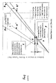
Figure 1 shows two different gain curves for a dual mode VON injector with corresponding aged gain curves. - Typically fuel injectors operate to inject fuel into a combustion space through a nozzle by cooperation of a needle with a nozzle. Operation of a fuel injector is typically via application of an electrical pulse to control e.g. a solenoid or piezoelectric valve arrangement. In a typical design of fuel injector the nozzle may comprise a plurality of individual orifices (e.g holes) formed in the nozzle, such that mode selection allows the needle displacement to provide injection through one or more nozzles selectively.
- VON injectors are capable of producing two different gain curves, for the two different modes, as shown in
figure 1 . On the x-axis is shown the duration of an electrical pulse sent to the fuel injector (time on) and the y-axis show the resultant amount of fuel injected, and the torque consequentially developed will be a function of the delivered fuel quantity. - As can be seen line A shows the gain curve (it is actually a straight line but traditionally these have been referred to as "curves") for one mode where a single orifice is open to allow discharge of fuel and line B shows the gain curve corresponding to the use of two orifices. As can be seen, the two orifice mode allows more fuel to be injected for the same duration of pulse signal sent to the injector. Gain curves A' and B' correspond to the gain curves for mode A and B with an aged injector, which generally results in a reduced amount of fuel injected, for the same pulse duration.
- As can be seen from the non-aged injector gain curves, when switching from the first mode A to the second mode B or vice versa, shown by bidirectional arrow E, the length of the electrical pulse has to be appropriately decreased /increased to achieve the same volume of fuel injected and hence torque. During calibration, the gain curves may be determined and the appropriate increase /decrease pulse length sent to injector determined in order to achieve the required volume of fuel/torque.
- However as the injector ages, the changes in the gain curves are such that the deterioration results in problems such that the similar control of the electrical pulses will not give the same results; arrow F illustrates such problems. As can be seen, initiating the same change in electrical pulse duration, as before will, for an aged injector, result in a step change G (decrease or increase) in the quantity of fuel delivered. This is manifested as a step change in torque and is undesirable.
- According to an aspect of the invention, when it is determined (e.g. as a result of an increase in demand torque) that there needs to be a change of mode, aspects of the invention provide for the switching of modes to be done progressively. This can be implemented in a variety of ways according to different aspects of the invention. The transition for each injector/cylinder in turn may occur after a set or variable time or a set or variable number of engine cycles, depending on operating conditions. This ensures that if there is a discrepancy in the gain curves, then the individual steps in the torque as each injector is switched, is less than if they were all switched together
- In a first example, during mode switching, the cylinders are switched one after another, e.g. in a progressive fashion. So for example in a 4 cylinder engine with one injector per cylinder, where there are two modes A and B and all the injectors are operating in mode A and there is a decision (e.g. based on torque demand) to switch to mode B, the first VON injector may be switched to mode B, and after a set period of time or number of engine cycles, the second VON injector is switched to mode B, and after a set period of time or number of engine cycles, the third injector is switched to mode B and so on. Thus, for example, in a four cylinder engine, the step torque is then only 25% of what it would have been otherwise. In other words after a decision to transition between modes, the injectors could transition progressively based on a time interval or after a certain number of engine cycles, thus reducing any large step change which may arise when all the injectors are switched at the same time.
- The injector modes may be controlled (switched) progressively according to another embodiment as follows. The control may be such that each injector is switched according to (different) torque demand. So where the absolute or relative torque demand reaches a certain point (e.g. threshold) a particular injector is switched (e.g. from mode A to mode B) and when the torque demand reaches a different threshold value, another injector has its mode switched from A to B. So where in prior art system all injectors are switched at 50% for example, according to this aspect, the injectors are switched progressively one at a time, over a certain period. So at 48% torque no injectors are switched, but at 52% torque first one is switched at 56% another injector is switched, until all injectors were switched.
- In another alternative strategy, the transition torque may be calibrated differently for each injector. This example is similar to the one described above, but rather than the ECU, for example, controlling when the injectors are switched, a single command is sent, e.g. indicative of demand torque, to the injectors, and injectors would be adapted to switch mode dependent on this demand torque and an inherently set threshold torque. Again each injector would be switched at a different engine torque. For instance the first injector at 45% torque the second at 50% the third at 55% etc. This means that if engine torque demand were at 48% torque continuously one injector would be switched and the other 3 not switched.
- In one aspect of the invention, to overcome the aforementioned problems, the relative drift in the gain curves for the different modes for a particular injector is tracked. One way of doing this is to select one of the injectors and switching this from one mode (e.g. two orifices to another mode (one orifice), or vice versa. The torque produced on the corresponding cylinder which has the fuel injector mode switched is measured and compared when operating in mode A and in mode B. This may be done separately to the mode transition, typically at a time when the engine is running at a fairly consistent torque which is near to the transition point. The measurement of torque differences is often already done in the cylinder balancing strategy - which looks at the crankshaft acceleration cylinder to cylinder and thus corrects injector drift cylinder to cylinder. Alternatively, in the event that cylinder pressure sensors are fitted then a suitable feedback signal on the fuel delivered in each operating mode can readily be obtained by that method. The two gain curves on the one injector can now be compared with each other rather than between different cylinders.
- Thus in an example, for a particular cylinder or injector, a switch of mode is made and the torque (or change in torque) for the two different modes is measured. If for example, the torque from mode A (one orifice/row operation) is 5% less than from mode B (two orifices/rows) operation, then mode A operation can be corrected/adjusted by increasing fuel flow, e.g. the electrical pulse duration, by 10%. (in the case of a 50:50 flow split). If the mode B (two row operation is 5% less than the mode A (one row operation) then likewise the two row (Mode B) operation of the injector can be corrected up by 10%.In general the following correction strategy may be applied:
- Rowl_Correction = max(0, (Delivery_row2 - Delivery_row1)/Delivery_row2 / (row2 % of total nominal injector flow))
- Row2_Correction = max(0, (Delivery_row1 - Delivery_row2)/Delivery_row1 / (row1 % of total nominal injector flow))
- In essence, for a particular torque, if switching from mode A to mode B reduces torque by a value of x%, then with respect to the correction factor, the fuel delivered in mode B is increased by an appropriate amount, which may be the value of x multiplied by a factor, said factor being a function of the ratio of effective orifice areas for the two modes.
- When a certain fuel delivery is demanded, the gain curve gives a "time on" (TON) value for the injector. It is common to adjust this value before it is applied to the injector. Corrections may be applied for the zero crossing point on the gain curve, the gradient, points of inflection, wear, pressure wave modulation etc. The benefit of applying the corrections as described above is that only one nominal gain curve is required for all injectors, over their whole lifetime, in any operating mode. The real gain curve of each injector at any point in its lifetime does not change, but the corrections allow the real gain curve to be adjusted to fit the nominal gain curve.
- The advantage of the above methodology is that one can be much more certain about a correction of this nature than a correction applied between cylinders using for instance the cylinder balancing strategy. This new strategy thus limits the total negative drift of the injector to the minimum of the drift of either row of the injector. This assumes that injector gain curve drift is only ever a reduction in the fuel delivered for a particular electrical pulse length. This advantage is provided because one is able to look and compare the performance on an individual cylinder with all other engine parameters(friction, air path, etc) exactly the same, except the injector operating mode (i.e. the effect of switching between 1 and 2 rows). Further it allows detection of failure to inject from one or the other rows by comparison of the gain curves with each other and with a maximum drift value for normal operation.
- Torque measurements (or estimates thereof e.g. from pressure measurements) are thus according to one aspect used to calibrate changes to the delivered fuel quantity. By making the measurements at two different torques, adjustments are made to the corrections for both to the gradient of the gain curve and to the zero crossing point. Additional measurement torques might allow more complicated gain curve shapes to also be characterised.
Claims (12)
- A method of controlling variable orifice nozzle fuel injectors in a combustion engine, said injectors being operable in at least two modes comprising: determining that there is a need to switch from a first mode to a second mode, and wherein switching of the modes is performed in progressive fashion.
- A method as claimed in claim 1 wherein the transition of modes for each injector is performed sequentially
- A method as claimed in claims 1 or 2 wherein the transition of modes for each injector is performed after a set time or a set number of engine cycles
- A method as claimed in claims 1 to 3 wherein the point at which transition occurs for each injector is performed at different set points
- A method as claimed in claim 4 wherein said injectors are controlled to switch mode dependent on a set value of demand torque, and wherein said set value is arranged to differ for different injectors.
- A method as claimed in any preceding claim wherein there is variation in the calibration of said injectors in terms of the point at which switching of modes takes place.
- A method of controlling and/or calibrating variable orifice nozzle fuel injectors in a combustion engine, said injectors being operable in at least two modes, comprising:i) switching one injector between a first mode and a second mode;ii) estimating or measuring the consequential torque or change in torque;iii) adjusting the operation of said injector with respect to one and/or the other of the two modes, dependent on the consequential change in torque.
- A method as claimed in claim 7 wherein said adjusting comprises proportionally/correspondingly varying the quantity of fuel delivered for a particular mode, at any set point.
- A method as claimed in claim 8 wherein said varying of the quantity of fuel is such that there is no corresponding change in torque when said injector is switched modes.
- A method as claimed in claims 8 to 10 wherein steps i) and ii) are performed separately to normal mode transition.
- A method as claimed in claims 8 to 11 wherein steps i) and ii) are performed, at a time when the engine is running at a substantially constant torque and or substantially close to the mode transition point.
- A system method of controlling variable orifice nozzle fuel injectors in a combustion engine including a plurality of variable orifice nozzle fuel injectors, said injectors being operable in at least two modes and adapted to implement any method according to claims 1 to 11.
Priority Applications (2)
| Application Number | Priority Date | Filing Date | Title |
|---|---|---|---|
| EP13197630.0A EP2886845A1 (en) | 2013-12-17 | 2013-12-17 | Method and system to operate a variable orifice nozzle fuel injector |
| PCT/EP2014/073653 WO2015090708A1 (en) | 2013-12-17 | 2014-11-04 | Method and system to operate a variable orifice nozzle fuel injector |
Applications Claiming Priority (1)
| Application Number | Priority Date | Filing Date | Title |
|---|---|---|---|
| EP13197630.0A EP2886845A1 (en) | 2013-12-17 | 2013-12-17 | Method and system to operate a variable orifice nozzle fuel injector |
Publications (1)
| Publication Number | Publication Date |
|---|---|
| EP2886845A1 true EP2886845A1 (en) | 2015-06-24 |
Family
ID=49841521
Family Applications (1)
| Application Number | Title | Priority Date | Filing Date |
|---|---|---|---|
| EP13197630.0A Withdrawn EP2886845A1 (en) | 2013-12-17 | 2013-12-17 | Method and system to operate a variable orifice nozzle fuel injector |
Country Status (2)
| Country | Link |
|---|---|
| EP (1) | EP2886845A1 (en) |
| WO (1) | WO2015090708A1 (en) |
Cited By (1)
| Publication number | Priority date | Publication date | Assignee | Title |
|---|---|---|---|---|
| CN109072803A (en) * | 2016-04-27 | 2018-12-21 | 法国大陆汽车公司 | Method for diagnosing the operation of the diesel engine injector of motor vehicles |
Citations (5)
| Publication number | Priority date | Publication date | Assignee | Title |
|---|---|---|---|---|
| DE19737375A1 (en) * | 1996-08-27 | 1998-03-05 | Mitsubishi Motors Corp | Direct fuel injection system for vehicle IC engine |
| US5803048A (en) * | 1994-04-08 | 1998-09-08 | Honda Giken Kogyo Kabushiki Kaisha | System and method for controlling air-fuel ratio in internal combustion engine |
| US20030029414A1 (en) * | 2000-07-22 | 2003-02-13 | Juergen Boss | Method for controlling an injection valve |
| WO2008152488A1 (en) * | 2007-06-15 | 2008-12-18 | Toyota Jidosha Kabushiki Kaisha | Apparatus and method for controlling a fuel injector under abnormal conditions |
| US20110202255A1 (en) * | 2008-10-15 | 2011-08-18 | Christian Hauser | Method for correcting injection quantities and/or times of a fuel injector |
-
2013
- 2013-12-17 EP EP13197630.0A patent/EP2886845A1/en not_active Withdrawn
-
2014
- 2014-11-04 WO PCT/EP2014/073653 patent/WO2015090708A1/en not_active Ceased
Patent Citations (5)
| Publication number | Priority date | Publication date | Assignee | Title |
|---|---|---|---|---|
| US5803048A (en) * | 1994-04-08 | 1998-09-08 | Honda Giken Kogyo Kabushiki Kaisha | System and method for controlling air-fuel ratio in internal combustion engine |
| DE19737375A1 (en) * | 1996-08-27 | 1998-03-05 | Mitsubishi Motors Corp | Direct fuel injection system for vehicle IC engine |
| US20030029414A1 (en) * | 2000-07-22 | 2003-02-13 | Juergen Boss | Method for controlling an injection valve |
| WO2008152488A1 (en) * | 2007-06-15 | 2008-12-18 | Toyota Jidosha Kabushiki Kaisha | Apparatus and method for controlling a fuel injector under abnormal conditions |
| US20110202255A1 (en) * | 2008-10-15 | 2011-08-18 | Christian Hauser | Method for correcting injection quantities and/or times of a fuel injector |
Cited By (2)
| Publication number | Priority date | Publication date | Assignee | Title |
|---|---|---|---|---|
| CN109072803A (en) * | 2016-04-27 | 2018-12-21 | 法国大陆汽车公司 | Method for diagnosing the operation of the diesel engine injector of motor vehicles |
| CN109072803B (en) * | 2016-04-27 | 2021-09-21 | 法国大陆汽车公司 | Method for diagnosing the operation of a diesel engine injector of a motor vehicle |
Also Published As
| Publication number | Publication date |
|---|---|
| WO2015090708A1 (en) | 2015-06-25 |
Similar Documents
| Publication | Publication Date | Title |
|---|---|---|
| US8807116B2 (en) | High operation repeatability and stability fuel injection system for an internal combustion engine | |
| US9002621B2 (en) | Method for correcting injection quantities and/or times of a fuel injector | |
| US7552709B2 (en) | Accumulator fuel injection apparatus compensating for injector individual variability | |
| KR101891008B1 (en) | Method for operating injectors of an injection system | |
| JP4089600B2 (en) | Injection quantity control device for internal combustion engine | |
| US8827175B2 (en) | Method and device for the calibration of fuel injectors | |
| US9765722B2 (en) | Fuel injection system for internal combustion engine and control method for internal combustion engine | |
| DE112011100884T5 (en) | Fuel injection control device | |
| CN102084110A (en) | Method and device for the pressure wave compensation of consecutive injections in an injection system of an internal combustion engine | |
| CN102057149A (en) | Method for detecting deviations of injection quantities and for correcting the injection quantity and injection system | |
| US7255087B2 (en) | Method for controlling an injection system of an internal combustion engine | |
| EP1860312B1 (en) | A Method of operating a fuel injector | |
| JP2010071187A (en) | Fuel injection control device | |
| JP6221913B2 (en) | Pump control device | |
| JP4710888B2 (en) | Diesel engine fuel injection control device and diesel engine fuel injection amount learning method | |
| US12516644B2 (en) | Pressure drop analysis strategy | |
| EP2886845A1 (en) | Method and system to operate a variable orifice nozzle fuel injector | |
| CN100379965C (en) | Method and device for operating an injection system of an internal combustion engine | |
| CN106988914B (en) | Method for controlling a magnetic valve injector | |
| JP5382006B2 (en) | Fuel injection control device | |
| US10495018B2 (en) | Method for defining learning area of injector opening duration control | |
| KR20180096561A (en) | Method for defining learning area of injector opening duration control | |
| KR20090005036A (en) | How the injection device works | |
| WO2011125371A1 (en) | Fuel injection control device and pressure accumulation type fuel injection device | |
| JP7364410B2 (en) | Fuel injection control device and control method for the fuel injection control device |
Legal Events
| Date | Code | Title | Description |
|---|---|---|---|
| PUAI | Public reference made under article 153(3) epc to a published international application that has entered the european phase |
Free format text: ORIGINAL CODE: 0009012 |
|
| 17P | Request for examination filed |
Effective date: 20131217 |
|
| AK | Designated contracting states |
Kind code of ref document: A1 Designated state(s): AL AT BE BG CH CY CZ DE DK EE ES FI FR GB GR HR HU IE IS IT LI LT LU LV MC MK MT NL NO PL PT RO RS SE SI SK SM TR |
|
| AX | Request for extension of the european patent |
Extension state: BA ME |
|
| R17P | Request for examination filed (corrected) |
Effective date: 20160104 |
|
| RAX | Requested extension states of the european patent have changed |
Extension state: BA Payment date: 20160104 Extension state: ME Payment date: 20160104 |
|
| RBV | Designated contracting states (corrected) |
Designated state(s): AL AT BE BG CH CY CZ DE DK EE ES FI FR GB GR HR HU IE IS IT LI LT LU LV MC MK MT NL NO PL PT RO RS SE SI SK SM TR |
|
| 17Q | First examination report despatched |
Effective date: 20160510 |
|
| STAA | Information on the status of an ep patent application or granted ep patent |
Free format text: STATUS: THE APPLICATION IS DEEMED TO BE WITHDRAWN |
|
| 18D | Application deemed to be withdrawn |
Effective date: 20160921 |