EP2886839A1 - Vehicle control device and vehicle control method - Google Patents
Vehicle control device and vehicle control method Download PDFInfo
- Publication number
- EP2886839A1 EP2886839A1 EP13879625.5A EP13879625A EP2886839A1 EP 2886839 A1 EP2886839 A1 EP 2886839A1 EP 13879625 A EP13879625 A EP 13879625A EP 2886839 A1 EP2886839 A1 EP 2886839A1
- Authority
- EP
- European Patent Office
- Prior art keywords
- air density
- target
- target engine
- engine output
- vehicle
- Prior art date
- Legal status (The legal status is an assumption and is not a legal conclusion. Google has not performed a legal analysis and makes no representation as to the accuracy of the status listed.)
- Granted
Links
Images





Classifications
-
- F—MECHANICAL ENGINEERING; LIGHTING; HEATING; WEAPONS; BLASTING
- F02—COMBUSTION ENGINES; HOT-GAS OR COMBUSTION-PRODUCT ENGINE PLANTS
- F02D—CONTROLLING COMBUSTION ENGINES
- F02D29/00—Controlling engines, such controlling being peculiar to the devices driven thereby, the devices being other than parts or accessories essential to engine operation, e.g. controlling of engines by signals external thereto
- F02D29/02—Controlling engines, such controlling being peculiar to the devices driven thereby, the devices being other than parts or accessories essential to engine operation, e.g. controlling of engines by signals external thereto peculiar to engines driving vehicles; peculiar to engines driving variable pitch propellers
-
- B—PERFORMING OPERATIONS; TRANSPORTING
- B60—VEHICLES IN GENERAL
- B60W—CONJOINT CONTROL OF VEHICLE SUB-UNITS OF DIFFERENT TYPE OR DIFFERENT FUNCTION; CONTROL SYSTEMS SPECIALLY ADAPTED FOR HYBRID VEHICLES; ROAD VEHICLE DRIVE CONTROL SYSTEMS FOR PURPOSES NOT RELATED TO THE CONTROL OF A PARTICULAR SUB-UNIT
- B60W10/00—Conjoint control of vehicle sub-units of different type or different function
- B60W10/04—Conjoint control of vehicle sub-units of different type or different function including control of propulsion units
- B60W10/06—Conjoint control of vehicle sub-units of different type or different function including control of propulsion units including control of combustion engines
-
- B—PERFORMING OPERATIONS; TRANSPORTING
- B60—VEHICLES IN GENERAL
- B60W—CONJOINT CONTROL OF VEHICLE SUB-UNITS OF DIFFERENT TYPE OR DIFFERENT FUNCTION; CONTROL SYSTEMS SPECIALLY ADAPTED FOR HYBRID VEHICLES; ROAD VEHICLE DRIVE CONTROL SYSTEMS FOR PURPOSES NOT RELATED TO THE CONTROL OF A PARTICULAR SUB-UNIT
- B60W10/00—Conjoint control of vehicle sub-units of different type or different function
- B60W10/10—Conjoint control of vehicle sub-units of different type or different function including control of change-speed gearings
-
- B—PERFORMING OPERATIONS; TRANSPORTING
- B60—VEHICLES IN GENERAL
- B60W—CONJOINT CONTROL OF VEHICLE SUB-UNITS OF DIFFERENT TYPE OR DIFFERENT FUNCTION; CONTROL SYSTEMS SPECIALLY ADAPTED FOR HYBRID VEHICLES; ROAD VEHICLE DRIVE CONTROL SYSTEMS FOR PURPOSES NOT RELATED TO THE CONTROL OF A PARTICULAR SUB-UNIT
- B60W20/00—Control systems specially adapted for hybrid vehicles
- B60W20/10—Controlling the power contribution of each of the prime movers to meet required power demand
-
- B—PERFORMING OPERATIONS; TRANSPORTING
- B60—VEHICLES IN GENERAL
- B60W—CONJOINT CONTROL OF VEHICLE SUB-UNITS OF DIFFERENT TYPE OR DIFFERENT FUNCTION; CONTROL SYSTEMS SPECIALLY ADAPTED FOR HYBRID VEHICLES; ROAD VEHICLE DRIVE CONTROL SYSTEMS FOR PURPOSES NOT RELATED TO THE CONTROL OF A PARTICULAR SUB-UNIT
- B60W30/00—Purposes of road vehicle drive control systems not related to the control of a particular sub-unit, e.g. of systems using conjoint control of vehicle sub-units
- B60W30/18—Propelling the vehicle
- B60W30/188—Controlling power parameters of the driveline, e.g. determining the required power
- B60W30/1882—Controlling power parameters of the driveline, e.g. determining the required power characterised by the working point of the engine, e.g. by using engine output chart
-
- F—MECHANICAL ENGINEERING; LIGHTING; HEATING; WEAPONS; BLASTING
- F02—COMBUSTION ENGINES; HOT-GAS OR COMBUSTION-PRODUCT ENGINE PLANTS
- F02D—CONTROLLING COMBUSTION ENGINES
- F02D11/00—Arrangements for, or adaptations to, non-automatic engine control initiation means, e.g. operator initiated
- F02D11/06—Arrangements for, or adaptations to, non-automatic engine control initiation means, e.g. operator initiated characterised by non-mechanical control linkages, e.g. fluid control linkages or by control linkages with power drive or assistance
- F02D11/10—Arrangements for, or adaptations to, non-automatic engine control initiation means, e.g. operator initiated characterised by non-mechanical control linkages, e.g. fluid control linkages or by control linkages with power drive or assistance of the electric type
- F02D11/105—Arrangements for, or adaptations to, non-automatic engine control initiation means, e.g. operator initiated characterised by non-mechanical control linkages, e.g. fluid control linkages or by control linkages with power drive or assistance of the electric type characterised by the function converting demand to actuation, e.g. a map indicating relations between an accelerator pedal position and throttle valve opening or target engine torque
-
- F—MECHANICAL ENGINEERING; LIGHTING; HEATING; WEAPONS; BLASTING
- F02—COMBUSTION ENGINES; HOT-GAS OR COMBUSTION-PRODUCT ENGINE PLANTS
- F02D—CONTROLLING COMBUSTION ENGINES
- F02D29/00—Controlling engines, such controlling being peculiar to the devices driven thereby, the devices being other than parts or accessories essential to engine operation, e.g. controlling of engines by signals external thereto
- F02D29/06—Controlling engines, such controlling being peculiar to the devices driven thereby, the devices being other than parts or accessories essential to engine operation, e.g. controlling of engines by signals external thereto peculiar to engines driving electric generators
-
- F—MECHANICAL ENGINEERING; LIGHTING; HEATING; WEAPONS; BLASTING
- F02—COMBUSTION ENGINES; HOT-GAS OR COMBUSTION-PRODUCT ENGINE PLANTS
- F02D—CONTROLLING COMBUSTION ENGINES
- F02D31/00—Use of speed-sensing governors to control combustion engines, not otherwise provided for
-
- F—MECHANICAL ENGINEERING; LIGHTING; HEATING; WEAPONS; BLASTING
- F02—COMBUSTION ENGINES; HOT-GAS OR COMBUSTION-PRODUCT ENGINE PLANTS
- F02D—CONTROLLING COMBUSTION ENGINES
- F02D31/00—Use of speed-sensing governors to control combustion engines, not otherwise provided for
- F02D31/001—Electric control of rotation speed
-
- F—MECHANICAL ENGINEERING; LIGHTING; HEATING; WEAPONS; BLASTING
- F02—COMBUSTION ENGINES; HOT-GAS OR COMBUSTION-PRODUCT ENGINE PLANTS
- F02D—CONTROLLING COMBUSTION ENGINES
- F02D41/00—Electrical control of supply of combustible mixture or its constituents
- F02D41/02—Circuit arrangements for generating control signals
- F02D41/021—Introducing corrections for particular conditions exterior to the engine
- F02D41/0215—Introducing corrections for particular conditions exterior to the engine in relation with elements of the transmission
-
- B—PERFORMING OPERATIONS; TRANSPORTING
- B60—VEHICLES IN GENERAL
- B60W—CONJOINT CONTROL OF VEHICLE SUB-UNITS OF DIFFERENT TYPE OR DIFFERENT FUNCTION; CONTROL SYSTEMS SPECIALLY ADAPTED FOR HYBRID VEHICLES; ROAD VEHICLE DRIVE CONTROL SYSTEMS FOR PURPOSES NOT RELATED TO THE CONTROL OF A PARTICULAR SUB-UNIT
- B60W2540/00—Input parameters relating to occupants
- B60W2540/10—Accelerator pedal position
-
- B—PERFORMING OPERATIONS; TRANSPORTING
- B60—VEHICLES IN GENERAL
- B60W—CONJOINT CONTROL OF VEHICLE SUB-UNITS OF DIFFERENT TYPE OR DIFFERENT FUNCTION; CONTROL SYSTEMS SPECIALLY ADAPTED FOR HYBRID VEHICLES; ROAD VEHICLE DRIVE CONTROL SYSTEMS FOR PURPOSES NOT RELATED TO THE CONTROL OF A PARTICULAR SUB-UNIT
- B60W2555/00—Input parameters relating to exterior conditions, not covered by groups B60W2552/00, B60W2554/00
- B60W2555/20—Ambient conditions, e.g. wind or rain
-
- B—PERFORMING OPERATIONS; TRANSPORTING
- B60—VEHICLES IN GENERAL
- B60W—CONJOINT CONTROL OF VEHICLE SUB-UNITS OF DIFFERENT TYPE OR DIFFERENT FUNCTION; CONTROL SYSTEMS SPECIALLY ADAPTED FOR HYBRID VEHICLES; ROAD VEHICLE DRIVE CONTROL SYSTEMS FOR PURPOSES NOT RELATED TO THE CONTROL OF A PARTICULAR SUB-UNIT
- B60W2710/00—Output or target parameters relating to a particular sub-units
- B60W2710/06—Combustion engines, Gas turbines
- B60W2710/0666—Engine torque
-
- F—MECHANICAL ENGINEERING; LIGHTING; HEATING; WEAPONS; BLASTING
- F02—COMBUSTION ENGINES; HOT-GAS OR COMBUSTION-PRODUCT ENGINE PLANTS
- F02D—CONTROLLING COMBUSTION ENGINES
- F02D2200/00—Input parameters for engine control
- F02D2200/02—Input parameters for engine control the parameters being related to the engine
- F02D2200/04—Engine intake system parameters
- F02D2200/0414—Air temperature
-
- F—MECHANICAL ENGINEERING; LIGHTING; HEATING; WEAPONS; BLASTING
- F02—COMBUSTION ENGINES; HOT-GAS OR COMBUSTION-PRODUCT ENGINE PLANTS
- F02D—CONTROLLING COMBUSTION ENGINES
- F02D2200/00—Input parameters for engine control
- F02D2200/50—Input parameters for engine control said parameters being related to the vehicle or its components
- F02D2200/501—Vehicle speed
-
- F—MECHANICAL ENGINEERING; LIGHTING; HEATING; WEAPONS; BLASTING
- F02—COMBUSTION ENGINES; HOT-GAS OR COMBUSTION-PRODUCT ENGINE PLANTS
- F02D—CONTROLLING COMBUSTION ENGINES
- F02D2200/00—Input parameters for engine control
- F02D2200/60—Input parameters for engine control said parameters being related to the driver demands or status
- F02D2200/602—Pedal position
-
- F—MECHANICAL ENGINEERING; LIGHTING; HEATING; WEAPONS; BLASTING
- F02—COMBUSTION ENGINES; HOT-GAS OR COMBUSTION-PRODUCT ENGINE PLANTS
- F02D—CONTROLLING COMBUSTION ENGINES
- F02D2200/00—Input parameters for engine control
- F02D2200/70—Input parameters for engine control said parameters being related to the vehicle exterior
- F02D2200/703—Atmospheric pressure
-
- F—MECHANICAL ENGINEERING; LIGHTING; HEATING; WEAPONS; BLASTING
- F02—COMBUSTION ENGINES; HOT-GAS OR COMBUSTION-PRODUCT ENGINE PLANTS
- F02D—CONTROLLING COMBUSTION ENGINES
- F02D2250/00—Engine control related to specific problems or objectives
- F02D2250/18—Control of the engine output torque
Definitions
- the present invention relates to a vehicle control and a vehicle control method.
- the vehicle is controlled by calculating a target drive force based on a vehicle speed and an accelerator pedal opening and calculating a speed ratio and a target engine torque in accordance with an optimal fuel consumption line.
- the engine combusts fuel by taking in air. Since an air density is low, for example, in the case of traveling in highland, an actual engine torque may become lower than a target engine torque, the vehicle may not be controlled in accordance with the optimal fuel consumption line and fuel economy may be deteriorated even if the target engine torque is calculated in accordance with the optimal fuel consumption line and the engine is controlled to achieve the target engine torque.
- a target engine torque is calculated based on an air density and a reduction of an actual engine torque due to the air density is suppressed by controlling an engine based on the calculated target engine torque.
- the above invention has a problem that, if the air density is low, the engine torque reaches an upper limit value when an accelerator pedal opening is in an intermediate opening region, and an increase amount of an engine output in relation to the depression of an accelerator pedal becomes smaller to reduce driving performance of the vehicle when the accelerator pedal is further depressed thereafter.
- the present invention was developed to solve such a problem and aims to suppress a reduction in driving performance of a vehicle even if an air density is low.
- a vehicle control device for controlling a vehicle with an engine and includes target drive force calculation means configured to calculate a target drive force based on a driving state of the vehicle, vehicle speed detection means configured to detect a vehicle speed of the vehicle, air density calculation means configured to calculate an air density, target engine output calculation means configured to calculate a target engine output based on the target drive force, the vehicle speed and the air density, and target engine torque calculation means configured to calculate a target engine torque based on the target engine output and the air density.
- the target engine output calculation means is configured to set a smaller target engine output when the air density is low than when the air density is high.
- the target engine torque calculation means is configured to set a larger target engine torque when the air density is low than when the air density is high.
- FIG. 1 is a schematic configuration diagram of the vehicle 100 of the present embodiment.
- the vehicle 100 includes an engine 1 as a motive power source, a drive system 2 for transmitting an output of the engine 1 to wheels 9 and a controller 3 for controlling the engine 1 and the drive system 2.
- the drive system 2 includes a torque converter 4, a forward/reverse switching mechanism 5, an automatic transmission 6, a final reduction differential device 7 and drive shafts 8.
- the torque converter 4 includes a lock-up clutch (not shown).
- the torque converter 4 is switched to a lock-up state where the lock-up clutch is completely engaged, a converter state where the lock-up clutch is completely released and a slip state where the lock-up clutch is half-engaged.
- the forward/reverse switching mechanism 5 includes a planetary gear set as a main constituent element and switches a rotation transmitting state between the engine 1 and the automatic transmission 6 by engaging or releasing a forward clutch and a reverse brake.
- the forward/reverse switching mechanism 5 transmits rotation produced in the engine 1 without changing a rotating direction when the forward clutch is engaged and the reverse brake is released, and transmits the rotation produced in the engine 1 while reversing the rotating direction when the forward clutch is released and the reverse brake is engaged.
- the automatic transmission 6 is a continuously variable transmission including a primary pulley, a secondary pulley and a belt mounted on the primary pulley and the secondary pulley. A speed ratio is changed by changing a contact radius of the belt and each pulley.
- the final reduction differential device 7 is an integrated assembly of a final speed reducer and a differential device and transmits rotation transmitted from an output shaft of the automatic transmission 6 to the left and right drive shafts 8 after reducing the speed of the rotation. Further, the final reduction differential device 7 automatically gives a speed difference to enable smooth traveling when it is necessary to create a speed difference between the rotation speeds of the left and right drive shafts 8 such as at the time of traveling on a curve.
- the wheel 9 is mounted on the tip of each of the left and right drive shafts 8.
- the controller 3 is configured by a microcomputer including a central processing unit (CPU), a read-only memory (ROM), a random access memory (RAM) and an input/output interface (I/O interface).
- CPU central processing unit
- ROM read-only memory
- RAM random access memory
- I/O interface input/output interface
- the controller 3 controls the engine 1, the torque converter 4, the forward/reverse switching mechanism 5 and the automatic transmission 6 based on the input signals.
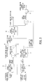
- FIG. 2 is a block diagram for the calculation of the target engine torque correction value and the target engine rotation speed. Calculations described here are performed by the controller 3.
- An air density calculation unit 30 calculates an air density based on the atmospheric pressure around the vehicle 100. Specifically, the air density is calculated by dividing the current atmospheric pressure detected by the atmospheric pressure sensor 21 by a standard air pressure. The air density is low, for example, when the vehicle 100 travels in highland.
- An air density correction coefficient calculation unit 31 calculates an air density correction coefficient from the air density based on a map shown in FIG. 3.
- FIG. 3 is a map showing a relationship of the air density and the air density correction coefficient.
- the air density correction coefficient is 1 when the air density is 1 and is smaller than 1 when the air density is lower than 1.
- a target drive force calculation unit 32 calculates a target drive force from the accelerator pedal opening and the vehicle speed based on a map shown in FIG. 4.
- FIG. 4 is a map showing a relationship of the accelerator pedal opening, the vehicle speed and the target drive force. The target drive force becomes smaller when the vehicle speed increases and becomes larger when the accelerator pedal opening increases.
- a target engine output calculation unit 33 is composed of a first target engine output calculation unit 34 and a second target engine output calculation unit 35.
- the first target engine output calculation unit 34 calculates a target engine output by multiplying the target drive force and the vehicle speed.
- the second target engine output calculation unit 35 calculates a target engine output correction value, which becomes a final target engine output, by multiplying the target engine output and the air density correction coefficient.
- the target engine output correction value is a value smaller than the target engine output calculated by the first engine output calculation unit 34 when the air density is lower than 1.
- a target rotation speed calculation unit 36 calculates a target engine rotation speed from the target engine output correction value based on a map shown in FIG. 5.
- FIG. 5 is a map showing a relationship of the target engine rotation speed, the target engine output, a target engine torque and an optimal fuel consumption line. Specifically, the target rotation speed calculation unit 36 calculates the target engine rotation speed, which provides optimal fuel consumption, from the target engine output correction value in accordance with the optimal fuel consumption line.
- a target engine torque calculation unit 37 calculates the target engine torque by dividing the target engine output correction value by the target engine rotation speed. This target engine torque is a value which is not corrected based on the air density. If the engine 1 is controlled to generate this target engine torque, an actual engine torque is smaller than the target engine torque if the air density is low, thereby deviating from the optimal fuel consumption line shown in FIG. 5 .
- a target engine torque correction calculation unit 38 calculates a target engine torque correction value, which becomes a final target engine torque, by dividing the target engine torque by the air density.
- the target engine torque correction value is a value corrected based on the air density and is larger than the target engine torque when the air density is low.
- the controller 3 calculates a target speed ratio by dividing the target engine rotation speed by a secondary pulley rotation speed calculated from the vehicle speed and controls the automatic transmission 6 so that a speed ratio of the automatic transmission 6 reaches the target speed ratio.
- the lock-up clutch is engaged and the engine rotation speed and the primary pulley rotation speed have the same value.
- the controller 3 controls the engine 1 by controlling a throttle opening, fuel injection into the engine 1 and the like based on the target engine torque correction value.
- FIGS. 6 and 7 Relationships of the accelerator pedal opening and the engine output when the vehicle 100 is caused to travel using the present embodiment are described using FIGS. 6 and 7 .
- FIG. 6 shows relationships of the accelerator pedal opening and the engine output in the vehicle 100 in which the target engine output is the one when the vehicle 100 travels in flatland where the air density is not low and the engine torque is corrected based on the air density without using the present embodiment.
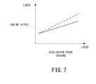
- FIG. 7 shows relationships of the accelerator pedal opening and the engine output when the present embodiment is used.
- the relationship of the accelerator pedal opening and the engine output when the vehicle 100 travels in flatland is shown in broken line and the relationship of the accelerator pedal opening and the engine output when the vehicle 100 travels in highland is shown in solid line.
- the engine output increases according to an increase of the accelerator pedal opening in a region where the accelerator pedal opening is smaller than a predetermined opening (region A in FIG. 6 ) if a driver depresses the accelerator pedal.
- the target engine output is set at the same value as in the case of traveling in flatland and the engine torque is corrected to be equal to the one in the case of traveling in flatland, the engine output is equal to the one in the case of traveling in flatland even in the case of traveling in highland.
- an increase amount of the engine output decreases even if the accelerator pedal opening increases according to the depression of the accelerator pedal by the driver. This is because the engine torque reaches an upper limit value since the engine torque is increased to become equal to the engine output in the case of traveling in flatland.
- the increase amount of the engine output of the vehicle 100 decreases before and after the accelerator pedal opening crosses the predetermined opening, e.g. the increase amount of the engine output decreases while the accelerator pedal is being depressed, thereby giving a sense of incongruity to the driver and reducing driving performance of the vehicle 100.
- the target engine output correction value is calculated based on the air density.
- the target engine output correction value is reduced.
- the target engine rotation speed and the target engine torque correction value based on the target engine output correction value are calculated and the engine 1 is controlled.
- the engine output becomes lower than the one in the case of traveling in flatland in this way, it can be suppressed that the engine torque reaches the upper limit value and the vehicle 100 can be caused to travel by gradually increasing the engine output according to the depression of the accelerator pedal by the driver.
- a reduction in the increase amount of the engine output while the accelerator pedal is being depressed can be suppressed and a reduction in driving performance of the vehicle 100 can be suppressed by not giving any sense of incongruity to the driver.
- the engine output can be increased according to the depression of the accelerator pedal and a reduction in driving performance of the vehicle 100 can be suppressed even if the accelerator pedal is depressed to increase the accelerator pedal opening. Further, by setting a larger target engine torque correction value, which becomes the final target engine torque, when the air density is low than when the air density is high, traveling in accordance with the optimal fuel consumption line can be enabled and fuel economy can be improved.
- Parts of the second embodiment different from the first embodiment are described.
- the configuration of the vehicle 100 is the same as in the first embodiment.
- the second embodiment differs from the first embodiment in the methods for calculating the target engine torque correction value and the target engine rotation speed.
- the methods for calculating the target engine torque correction value and the target engine rotation speed are described using FIG. 8.
- FIG. 8 is a block diagram for the calculation of the target engine torque correction value and the target engine rotation speed.
- the same calculation units as in the first embodiment are denoted by the same reference signs and not described here.
- a first target engine output calculation unit 40 calculates a target drive force correction value by multiplying a target drive force and an air density correction coefficient.
- a second target engine output calculation unit 41 calculates a target engine output by multiplying the target drive force correction value and a vehicle speed. This target engine output is a target engine output corrected based on the air density.
- a target rotation speed calculation unit 36 calculates the target engine rotation speed based on the calculated target engine output.
- a rotation speed ratio calculation unit 42 calculates a rotation speed ratio by dividing the target engine rotation speed by a wheel shaft rotation speed detected by a vehicle speed sensor 23.
- a target engine torque calculation unit 43 calculates a target engine torque by dividing the target drive force correction value by the rotation speed ratio.
- a vehicle 101 of the present embodiment is a hybrid vehicle.
- FIG. 9 is a schematic configuration diagram of the hybrid vehicle of the present embodiment. The same components as in the first embodiment are denoted by the same reference signs as in the first embodiment and not described here.
- the hybrid vehicle includes an engine 1 and a motor generator 50 as motive power sources, a battery 51 as an electric power source, an inverter 52 for controlling the motor generator 50, a drive system 53 for transmitting an output of the motive power source to wheels 9, an auxiliary machine 54, and a controller 3 for controlling the engine 1, the motor generator 50, the drive system 53 and the auxiliary machine 54.
- the motor generator 50 is a synchronous type motor generator in which a permanent magnet is embedded in a rotor and a stator coil is wound around a stator.
- the motor generator 50 has a function as a motor to be rotated and driven upon receiving the supply of electric power and a function as a generator for generating electromotive forces at opposite ends of the stator coil when the rotor is rotated by an external force.
- the battery 51 supplies electric power to various electrical components such as the motor generator 50 and stores electric power generated by the motor generator 50.
- the inverter 52 is a current converter for converting two types of electricity, i.e. a direct current and an alternating current into each other.
- the inverter 52 supplies a direct current from the battery 51 to the motor generator 50 after converting it into a three-phase alternating current of an arbitrary frequency.
- the motor generator 50 functions as a generator, a three-phase alternating current from the motor generator 50 is supplied to the battery 51 after being converted into a direct current.
- the drive system 53 includes a first clutch 60, an automatic transmission 61, a second clutch 62, a final reduction differential device 7 and drive shafts 8.
- the first clutch 60 is provided between the engine 1 and the motor generator 50.
- the first clutch 60 is a wet multi-disc clutch capable of continuously changing a torque capacity by controlling an oil flow rate and a hydraulic pressure by a first solenoid valve.
- the first clutch 60 is controlled in three states including an engaged state, a slip state (half-clutch state) and a released state by changing the torque capacity.
- the automatic transmission 61 is a stepped transmission with seven forward gear positions and one reverse gear position.
- the automatic transmission 61 includes four sets of planetary gear mechanisms and a plurality of frictional engagement elements (three sets of multi-disk clutches, four sets of multi-disc brakes and two sets of one-way clutches) connected to a plurality of rotary elements constituting the planetary gear mechanisms to change linked states of those.
- a gear position is switched by adjusting a hydraulic pressure supplied to each frictional engagement element and changing an engaged/released state of each frictional engagement element.
- the second clutch 62 is a wet multi-disc clutch capable of continuously changing the torque capacity by controlling the oil flow rate and the hydraulic pressure by a second solenoid valve.
- the second clutch 62 is controlled in three states including an engaged state, a slip state (half-clutch state) and a released state by changing the torque capacity.
- some of the plurality of frictional engagement elements provided in the automatic transmission 61 are used as the second clutch 62.
- the auxiliary machine 54 operates when a part of the rotation of the engine 1 is transmitted thereto.
- a signal from an accelerator pedal opening sensor 20 for detecting an accelerator pedal opening a signal from an atmospheric pressure sensor 21 for detecting an atmospheric pressure around the vehicle 101, a signal from a temperature sensor 22 for detecting an outside temperature, a signal from a vehicle speed sensor 23 for detecting a vehicle speed, a signal from a motor generator rotation speed sensor 70 for detecting a rotation speed of the motor generator 50, a signal from an SOC (State of Charge) sensor 71 for detecting an SOC of the battery 51, a signal from an engine rotation speed sensor 72 for detecting an engine rotation speed, a signal for transmitting an operational status of the auxiliary machine 54 and the like.
- the controller 3 controls the engine 1, the motor generator 50, the first clutch 60, the auxiliary machine 54 and the automatic transmission 61 based on the input signals.
- FIG. 10 is a block diagram for the calculation of the target engine torque correction value and the target engine rotation speed.
- the same calculation units as in the first embodiment are denoted by the same reference signs as in the first embodiment and not described here.
- An auxiliary machine torque calculation unit 80 calculates an auxiliary machine load torque necessary to operate the auxiliary machine 54 based on the operational status of the auxiliary machine 54.
- a target engine output calculation unit 81 is composed of a first target engine output calculation unit 34, a second target engine output calculation unit 35, a motor output calculation unit 82, an auxiliary machine output calculation unit 83 and a third target engine output calculation unit 84.
- the second target engine output calculation unit 35 calculates a first target engine output correction value (first engine output) by multiplying a target engine output and an air density correction coefficient.
- the motor output calculation unit 82 calculates a target motor output correction value based on the SOC of the battery 51 and the air density correction coefficient.
- the motor output calculation unit 82 is described in detail using FIG. 11 .
- the motor output calculation unit 82 calculates the target motor output based on a map showing a relationship of the SOC and the target motor output.
- the target motor output has a negative value.
- the motor generator 50 functions as a motor.
- the motor generator 50 functions as a generator and the motor generator 50 is driven to generate power by the engine 1.
- the predetermined SOC is a value which is set in advance and determines whether or not the battery 51 needs to be charged.
- the motor output calculation unit 82 selects an air density coefficient and calculates a target motor output correction value (third engine output) by multiplying the target motor output and the air density coefficient when the target motor output is negative, i.e. when the motor generator 50 is driven to generate power by the engine 1. Since the air density coefficient is smaller than 1 when the air density is lower than 1, the absolute value of the target motor output correction value is a value smaller than that of the target motor output. Since the air density coefficient is 1 when the air density is 1, the absolute value of the target motor output correction value is equal to that of the target motor output. When the target motor output is negative, the target motor output correction value is a value corrected based on the air density.
- the motor output calculation unit 82 selects 1 instead of the air density coefficient and calculates the target motor output correction value by multiplying the target motor output by 1 when the target motor output is positive, i.e. when the motor generator 50 functions as a motor.
- the target motor output correction value is a value not corrected based on the air density.
- the auxiliary machine output calculation unit 83 calculates an auxiliary machine engine output (second engine output) by multiplying the auxiliary machine load torque and the engine rotation speed.
- the auxiliary machine engine output is a value not corrected based on the air density. If the engine output necessary to operate the auxiliary machine 54 is corrected based on the air density, it may not be possible to sufficiently operate the auxiliary machine 54 when the air density is low. Thus, the auxiliary machine engine output is not corrected according to the air density.
- the third target engine output calculation unit 84 calculates a second target engine output correction value by adding the first target engine output correction value and the auxiliary machine engine output and subtracting the target motor output correction value. Since the target motor output correction value is a negative value when the motor generator 50 is driven to generate power by the engine 1, the target motor output correction value acts to increase the second target engine output correction value in this case.
- the target engine rotation speed and the like are calculated using the second target engine output correction value in the target rotation speed calculation unit 36 and the like.
- the controller 3 controls the automatic transmission 61 and the engine 1 and further controls the motor generator 50 based on the target motor output correction value.
- the auxiliary machine engine output necessary to operate the auxiliary machine 54 is not corrected based on the air density, the auxiliary machine engine output for operating the auxiliary machine 54 is certainly output from the engine 1 even if the air density is low and the second target engine output correction value is small. In this way, the shortage of the auxiliary machine engine output can be prevented and the auxiliary machine 54 can be sufficiently operated.
- the target motor output is corrected based on the air density to make the target motor output correction value smaller than the target motor output. In this way, it is possible to charge the battery 51 by generating power by the motor generator 50 while suppressing a reduction in driving performance of the vehicle 101.
- forward/reverse switching mechanism 5 is provided between the automatic transmission 6 and the engine 1 in the first and second embodiments, it may be provided between the automatic transmission 6 and the wheels 9.
- a continuously variable transmission is used as the automatic transmission 6 in the first and second embodiments and a stepped transmission is used as the automatic transmission 61 in the third embodiment, there is no limitation to these.
- a stepped transmission may be used in the first and second embodiments and a continuously variable transmission may be used in the third embodiment.
- the second clutch 62 of the hybrid vehicle may be separately provided between the motor generator 50 and the automatic transmission 61 as shown in FIG. 12 or may be separately provided behind the automatic transmission 61 as shown in FIG. 13 .
- the second clutch 62 has only to be provided between the motor generator 50 and the wheels 9.
- an altitude may be detected from information such as that of a car navigation system and the air density may be calculated based on the altitude. Further, the air density may be corrected based on the temperature detected by the temperature sensor 22.
Landscapes
- Engineering & Computer Science (AREA)
- Chemical & Material Sciences (AREA)
- Combustion & Propulsion (AREA)
- Mechanical Engineering (AREA)
- General Engineering & Computer Science (AREA)
- Transportation (AREA)
- Automation & Control Theory (AREA)
- Control Of Vehicle Engines Or Engines For Specific Uses (AREA)
- Hybrid Electric Vehicles (AREA)
- Electric Propulsion And Braking For Vehicles (AREA)
- Combined Controls Of Internal Combustion Engines (AREA)
Abstract
Description
- The present invention relates to a vehicle control and a vehicle control method.
- To improve fuel economy of an engine in a vehicle, the vehicle is controlled by calculating a target drive force based on a vehicle speed and an accelerator pedal opening and calculating a speed ratio and a target engine torque in accordance with an optimal fuel consumption line.
- The engine combusts fuel by taking in air. Since an air density is low, for example, in the case of traveling in highland, an actual engine torque may become lower than a target engine torque, the vehicle may not be controlled in accordance with the optimal fuel consumption line and fuel economy may be deteriorated even if the target engine torque is calculated in accordance with the optimal fuel consumption line and the engine is controlled to achieve the target engine torque.
- Contrary to this, in an invention described in
JP2001-47892A - The above invention has a problem that, if the air density is low, the engine torque reaches an upper limit value when an accelerator pedal opening is in an intermediate opening region, and an increase amount of an engine output in relation to the depression of an accelerator pedal becomes smaller to reduce driving performance of the vehicle when the accelerator pedal is further depressed thereafter.
- The present invention was developed to solve such a problem and aims to suppress a reduction in driving performance of a vehicle even if an air density is low.
- A vehicle control device according to one aspect of the present invention is a vehicle control device for controlling a vehicle with an engine and includes target drive force calculation means configured to calculate a target drive force based on a driving state of the vehicle, vehicle speed detection means configured to detect a vehicle speed of the vehicle, air density calculation means configured to calculate an air density, target engine output calculation means configured to calculate a target engine output based on the target drive force, the vehicle speed and the air density, and target engine torque calculation means configured to calculate a target engine torque based on the target engine output and the air density. The target engine output calculation means is configured to set a smaller target engine output when the air density is low than when the air density is high. The target engine torque calculation means is configured to set a larger target engine torque when the air density is low than when the air density is high.
- Embodiments of the present embodiment and advantages of the present embodiments are described in detail below with reference to the accompanying drawings.
-
-
FIG. 1 is a schematic configuration diagram of a vehicle of a first embodiment, -
FIG. 2 is a block diagram for the calculation of a target engine torque correction value and a target engine rotation speed in the first embodiment, -
FIG. 3 is a map showing a relationship of air density and air density correction coefficient, -
FIG. 4 is a map showing a relationship of accelerator pedal opening, vehicle speed and target drive force, -
FIG. 5 is a map showing a relationship of target engine rotation speed, target engine output, target engine torque and optimal fuel consumption line, -
FIG. 6 is a map showing relationships of accelerator pedal opening and engine output when the first embodiment is not used, -
FIG. 7 is a map showing relationships of accelerator pedal opening and engine output when the first embodiment is used, -
FIG. 8 is a block diagram for the calculation of a target engine torque correction value and a target engine rotation speed in a second embodiment, -
FIG. 9 is a schematic configuration diagram of a hybrid vehicle of a third embodiment, -
FIG. 10 is a block diagram for the calculation of a target engine torque correction value and a target engine rotation speed in a third embodiment, -
FIG. 11 is a block diagram showing the procedure of calculating a target motor output in a motor output calculation unit of the third embodiment,FIG. 12 is a diagram showing a modification of the embodiments, and -
FIG. 13 is a diagram showing a modification of the embodiments. - A
vehicle 100 of a first embodiment of the present invention is described usingFIG. 1. FIG. 1 is a schematic configuration diagram of thevehicle 100 of the present embodiment. - The
vehicle 100 includes anengine 1 as a motive power source, adrive system 2 for transmitting an output of theengine 1 towheels 9 and acontroller 3 for controlling theengine 1 and thedrive system 2. - The
drive system 2 includes atorque converter 4, a forward/reverse switching mechanism 5, anautomatic transmission 6, a final reductiondifferential device 7 anddrive shafts 8. - The
torque converter 4 includes a lock-up clutch (not shown). Thetorque converter 4 is switched to a lock-up state where the lock-up clutch is completely engaged, a converter state where the lock-up clutch is completely released and a slip state where the lock-up clutch is half-engaged. - The forward/
reverse switching mechanism 5 includes a planetary gear set as a main constituent element and switches a rotation transmitting state between theengine 1 and theautomatic transmission 6 by engaging or releasing a forward clutch and a reverse brake. The forward/reverse switching mechanism 5 transmits rotation produced in theengine 1 without changing a rotating direction when the forward clutch is engaged and the reverse brake is released, and transmits the rotation produced in theengine 1 while reversing the rotating direction when the forward clutch is released and the reverse brake is engaged. - The
automatic transmission 6 is a continuously variable transmission including a primary pulley, a secondary pulley and a belt mounted on the primary pulley and the secondary pulley. A speed ratio is changed by changing a contact radius of the belt and each pulley. - The final reduction
differential device 7 is an integrated assembly of a final speed reducer and a differential device and transmits rotation transmitted from an output shaft of theautomatic transmission 6 to the left andright drive shafts 8 after reducing the speed of the rotation. Further, the final reductiondifferential device 7 automatically gives a speed difference to enable smooth traveling when it is necessary to create a speed difference between the rotation speeds of the left andright drive shafts 8 such as at the time of traveling on a curve. Thewheel 9 is mounted on the tip of each of the left andright drive shafts 8. - The
controller 3 is configured by a microcomputer including a central processing unit (CPU), a read-only memory (ROM), a random access memory (RAM) and an input/output interface (I/O interface). - To the
controller 3 are input a signal from an acceleratorpedal opening sensor 20 for detecting an accelerator pedal opening, a signal from anatmospheric pressure sensor 21 for detecting an atmospheric pressure around thevehicle 100, a signal from atemperature sensor 22 for detecting an outside temperature, a signal from avehicle speed sensor 23 for detecting a vehicle speed and the like. Thecontroller 3 controls theengine 1, thetorque converter 4, the forward/reverse switching mechanism 5 and theautomatic transmission 6 based on the input signals. - Next, methods for calculating a target engine torque correction value and a target engine rotation speed in the present embodiment are described using
FIG. 2. FIG. 2 is a block diagram for the calculation of the target engine torque correction value and the target engine rotation speed. Calculations described here are performed by thecontroller 3. - An air
density calculation unit 30 calculates an air density based on the atmospheric pressure around thevehicle 100. Specifically, the air density is calculated by dividing the current atmospheric pressure detected by theatmospheric pressure sensor 21 by a standard air pressure. The air density is low, for example, when thevehicle 100 travels in highland. - An air density correction
coefficient calculation unit 31 calculates an air density correction coefficient from the air density based on a map shown inFIG. 3. FIG. 3 is a map showing a relationship of the air density and the air density correction coefficient. The air density correction coefficient is 1 when the air density is 1 and is smaller than 1 when the air density is lower than 1. - A target drive
force calculation unit 32 calculates a target drive force from the accelerator pedal opening and the vehicle speed based on a map shown inFIG. 4. FIG. 4 is a map showing a relationship of the accelerator pedal opening, the vehicle speed and the target drive force. The target drive force becomes smaller when the vehicle speed increases and becomes larger when the accelerator pedal opening increases. - A target engine
output calculation unit 33 is composed of a first target engineoutput calculation unit 34 and a second target engineoutput calculation unit 35. - The first target engine
output calculation unit 34 calculates a target engine output by multiplying the target drive force and the vehicle speed. - The second target engine
output calculation unit 35 calculates a target engine output correction value, which becomes a final target engine output, by multiplying the target engine output and the air density correction coefficient. The target engine output correction value is a value smaller than the target engine output calculated by the first engineoutput calculation unit 34 when the air density is lower than 1. - A target rotation
speed calculation unit 36 calculates a target engine rotation speed from the target engine output correction value based on a map shown inFIG. 5. FIG. 5 is a map showing a relationship of the target engine rotation speed, the target engine output, a target engine torque and an optimal fuel consumption line. Specifically, the target rotationspeed calculation unit 36 calculates the target engine rotation speed, which provides optimal fuel consumption, from the target engine output correction value in accordance with the optimal fuel consumption line. - A target engine
torque calculation unit 37 calculates the target engine torque by dividing the target engine output correction value by the target engine rotation speed. This target engine torque is a value which is not corrected based on the air density. If theengine 1 is controlled to generate this target engine torque, an actual engine torque is smaller than the target engine torque if the air density is low, thereby deviating from the optimal fuel consumption line shown inFIG. 5 . - A target engine torque
correction calculation unit 38 calculates a target engine torque correction value, which becomes a final target engine torque, by dividing the target engine torque by the air density. The target engine torque correction value is a value corrected based on the air density and is larger than the target engine torque when the air density is low. By controlling theengine 1 based on the target engine torque correction value, the actual engine torque becomes the target engine torque to provide an engine torque conforming to the optimal fuel consumption line shown inFIG. 5 even if the air density is low. - The
controller 3 calculates a target speed ratio by dividing the target engine rotation speed by a secondary pulley rotation speed calculated from the vehicle speed and controls theautomatic transmission 6 so that a speed ratio of theautomatic transmission 6 reaches the target speed ratio. Here, it is assumed that the lock-up clutch is engaged and the engine rotation speed and the primary pulley rotation speed have the same value. Further, thecontroller 3 controls theengine 1 by controlling a throttle opening, fuel injection into theengine 1 and the like based on the target engine torque correction value. - Relationships of the accelerator pedal opening and the engine output when the
vehicle 100 is caused to travel using the present embodiment are described usingFIGS. 6 and7 . Here, a case is assumed where thevehicle 100 travels in highland where the air density is low.FIG. 6 shows relationships of the accelerator pedal opening and the engine output in thevehicle 100 in which the target engine output is the one when thevehicle 100 travels in flatland where the air density is not low and the engine torque is corrected based on the air density without using the present embodiment.FIG. 7 shows relationships of the accelerator pedal opening and the engine output when the present embodiment is used. InFIGS. 6 and7 , the relationship of the accelerator pedal opening and the engine output when thevehicle 100 travels in flatland is shown in broken line and the relationship of the accelerator pedal opening and the engine output when thevehicle 100 travels in highland is shown in solid line. - When the present embodiment is not used, the engine output increases according to an increase of the accelerator pedal opening in a region where the accelerator pedal opening is smaller than a predetermined opening (region A in
FIG. 6 ) if a driver depresses the accelerator pedal. Here, since the target engine output is set at the same value as in the case of traveling in flatland and the engine torque is corrected to be equal to the one in the case of traveling in flatland, the engine output is equal to the one in the case of traveling in flatland even in the case of traveling in highland. - However, in a region where the accelerator pedal opening is larger than the predetermined opening (region B in
FIG. 6 ), an increase amount of the engine output decreases even if the accelerator pedal opening increases according to the depression of the accelerator pedal by the driver. This is because the engine torque reaches an upper limit value since the engine torque is increased to become equal to the engine output in the case of traveling in flatland. As just described, the increase amount of the engine output of thevehicle 100 decreases before and after the accelerator pedal opening crosses the predetermined opening, e.g. the increase amount of the engine output decreases while the accelerator pedal is being depressed, thereby giving a sense of incongruity to the driver and reducing driving performance of thevehicle 100. - In the present embodiment, the target engine output correction value is calculated based on the air density. When the air density is low, the target engine output correction value is reduced. Then, The target engine rotation speed and the target engine torque correction value based on the target engine output correction value are calculated and the
engine 1 is controlled. Although the engine output becomes lower than the one in the case of traveling in flatland in this way, it can be suppressed that the engine torque reaches the upper limit value and thevehicle 100 can be caused to travel by gradually increasing the engine output according to the depression of the accelerator pedal by the driver. Thus, a reduction in the increase amount of the engine output while the accelerator pedal is being depressed can be suppressed and a reduction in driving performance of thevehicle 100 can be suppressed by not giving any sense of incongruity to the driver. - Effects of the first embodiment of the present invention are described.
- By setting a smaller target engine output correction value, which becomes the final target engine output, when the air density is low than when the air density is high, the engine output can be increased according to the depression of the accelerator pedal and a reduction in driving performance of the
vehicle 100 can be suppressed even if the accelerator pedal is depressed to increase the accelerator pedal opening. Further, by setting a larger target engine torque correction value, which becomes the final target engine torque, when the air density is low than when the air density is high, traveling in accordance with the optimal fuel consumption line can be enabled and fuel economy can be improved. - Next, a second embodiment of the present invention is described.
- Parts of the second embodiment different from the first embodiment are described. The configuration of the
vehicle 100 is the same as in the first embodiment. - The second embodiment differs from the first embodiment in the methods for calculating the target engine torque correction value and the target engine rotation speed. The methods for calculating the target engine torque correction value and the target engine rotation speed are described using
FIG. 8. FIG. 8 is a block diagram for the calculation of the target engine torque correction value and the target engine rotation speed. The same calculation units as in the first embodiment are denoted by the same reference signs and not described here. - A first target engine
output calculation unit 40 calculates a target drive force correction value by multiplying a target drive force and an air density correction coefficient. - A second target engine
output calculation unit 41 calculates a target engine output by multiplying the target drive force correction value and a vehicle speed. This target engine output is a target engine output corrected based on the air density. A target rotationspeed calculation unit 36 calculates the target engine rotation speed based on the calculated target engine output. - A rotation speed
ratio calculation unit 42 calculates a rotation speed ratio by dividing the target engine rotation speed by a wheel shaft rotation speed detected by avehicle speed sensor 23. - A target engine
torque calculation unit 43 calculates a target engine torque by dividing the target drive force correction value by the rotation speed ratio. - Effects of the second embodiment of the present invention are described.
- The same effects as in the first embodiment can be obtained also by the configuration of the present embodiment.
- Next, a third embodiment of the present invention is described.
- A
vehicle 101 of the present embodiment is a hybrid vehicle.FIG. 9 is a schematic configuration diagram of the hybrid vehicle of the present embodiment. The same components as in the first embodiment are denoted by the same reference signs as in the first embodiment and not described here. - The hybrid vehicle includes an
engine 1 and amotor generator 50 as motive power sources, abattery 51 as an electric power source, aninverter 52 for controlling themotor generator 50, adrive system 53 for transmitting an output of the motive power source towheels 9, anauxiliary machine 54, and acontroller 3 for controlling theengine 1, themotor generator 50, thedrive system 53 and theauxiliary machine 54. - The
motor generator 50 is a synchronous type motor generator in which a permanent magnet is embedded in a rotor and a stator coil is wound around a stator. Themotor generator 50 has a function as a motor to be rotated and driven upon receiving the supply of electric power and a function as a generator for generating electromotive forces at opposite ends of the stator coil when the rotor is rotated by an external force. - The
battery 51 supplies electric power to various electrical components such as themotor generator 50 and stores electric power generated by themotor generator 50. - The
inverter 52 is a current converter for converting two types of electricity, i.e. a direct current and an alternating current into each other. Theinverter 52 supplies a direct current from thebattery 51 to themotor generator 50 after converting it into a three-phase alternating current of an arbitrary frequency. On the other hand, when themotor generator 50 functions as a generator, a three-phase alternating current from themotor generator 50 is supplied to thebattery 51 after being converted into a direct current. - The
drive system 53 includes a first clutch 60, anautomatic transmission 61, a second clutch 62, a final reductiondifferential device 7 and driveshafts 8. - The first clutch 60 is provided between the
engine 1 and themotor generator 50. The first clutch 60 is a wet multi-disc clutch capable of continuously changing a torque capacity by controlling an oil flow rate and a hydraulic pressure by a first solenoid valve. The first clutch 60 is controlled in three states including an engaged state, a slip state (half-clutch state) and a released state by changing the torque capacity. - The
automatic transmission 61 is a stepped transmission with seven forward gear positions and one reverse gear position. Theautomatic transmission 61 includes four sets of planetary gear mechanisms and a plurality of frictional engagement elements (three sets of multi-disk clutches, four sets of multi-disc brakes and two sets of one-way clutches) connected to a plurality of rotary elements constituting the planetary gear mechanisms to change linked states of those. A gear position is switched by adjusting a hydraulic pressure supplied to each frictional engagement element and changing an engaged/released state of each frictional engagement element. - The second clutch 62 is a wet multi-disc clutch capable of continuously changing the torque capacity by controlling the oil flow rate and the hydraulic pressure by a second solenoid valve. The second clutch 62 is controlled in three states including an engaged state, a slip state (half-clutch state) and a released state by changing the torque capacity. In the present embodiment, some of the plurality of frictional engagement elements provided in the
automatic transmission 61 are used as thesecond clutch 62. - The
auxiliary machine 54 operates when a part of the rotation of theengine 1 is transmitted thereto. - To the
controller 3 are input a signal from an acceleratorpedal opening sensor 20 for detecting an accelerator pedal opening, a signal from anatmospheric pressure sensor 21 for detecting an atmospheric pressure around thevehicle 101, a signal from atemperature sensor 22 for detecting an outside temperature, a signal from avehicle speed sensor 23 for detecting a vehicle speed, a signal from a motor generatorrotation speed sensor 70 for detecting a rotation speed of themotor generator 50, a signal from an SOC (State of Charge)sensor 71 for detecting an SOC of thebattery 51, a signal from an enginerotation speed sensor 72 for detecting an engine rotation speed, a signal for transmitting an operational status of theauxiliary machine 54 and the like. Thecontroller 3 controls theengine 1, themotor generator 50, the first clutch 60, theauxiliary machine 54 and theautomatic transmission 61 based on the input signals. - Next, methods for calculating a target engine torque correction value and a target engine rotation speed are described using
FIG. 10. FIG. 10 is a block diagram for the calculation of the target engine torque correction value and the target engine rotation speed. The same calculation units as in the first embodiment are denoted by the same reference signs as in the first embodiment and not described here. - An auxiliary machine
torque calculation unit 80 calculates an auxiliary machine load torque necessary to operate theauxiliary machine 54 based on the operational status of theauxiliary machine 54. - A target engine
output calculation unit 81 is composed of a first target engineoutput calculation unit 34, a second target engineoutput calculation unit 35, a motoroutput calculation unit 82, an auxiliary machineoutput calculation unit 83 and a third target engineoutput calculation unit 84. - The second target engine
output calculation unit 35 calculates a first target engine output correction value (first engine output) by multiplying a target engine output and an air density correction coefficient. - The motor
output calculation unit 82 calculates a target motor output correction value based on the SOC of thebattery 51 and the air density correction coefficient. The motoroutput calculation unit 82 is described in detail usingFIG. 11 . - The motor
output calculation unit 82 calculates the target motor output based on a map showing a relationship of the SOC and the target motor output. When the SOC is lower than a predetermined SOC, the target motor output has a negative value. When the target motor output is positive, themotor generator 50 functions as a motor. When the target motor output is negative, themotor generator 50 functions as a generator and themotor generator 50 is driven to generate power by theengine 1. The predetermined SOC is a value which is set in advance and determines whether or not thebattery 51 needs to be charged. - The motor
output calculation unit 82 selects an air density coefficient and calculates a target motor output correction value (third engine output) by multiplying the target motor output and the air density coefficient when the target motor output is negative, i.e. when themotor generator 50 is driven to generate power by theengine 1. Since the air density coefficient is smaller than 1 when the air density is lower than 1, the absolute value of the target motor output correction value is a value smaller than that of the target motor output. Since the air density coefficient is 1 when the air density is 1, the absolute value of the target motor output correction value is equal to that of the target motor output. When the target motor output is negative, the target motor output correction value is a value corrected based on the air density. - The motor
output calculation unit 82 selects 1 instead of the air density coefficient and calculates the target motor output correction value by multiplying the target motor output by 1 when the target motor output is positive, i.e. when themotor generator 50 functions as a motor. When the target motor output is positive, the target motor output correction value is a value not corrected based on the air density. - The auxiliary machine
output calculation unit 83 calculates an auxiliary machine engine output (second engine output) by multiplying the auxiliary machine load torque and the engine rotation speed. The auxiliary machine engine output is a value not corrected based on the air density. If the engine output necessary to operate theauxiliary machine 54 is corrected based on the air density, it may not be possible to sufficiently operate theauxiliary machine 54 when the air density is low. Thus, the auxiliary machine engine output is not corrected according to the air density. - The third target engine
output calculation unit 84 calculates a second target engine output correction value by adding the first target engine output correction value and the auxiliary machine engine output and subtracting the target motor output correction value. Since the target motor output correction value is a negative value when themotor generator 50 is driven to generate power by theengine 1, the target motor output correction value acts to increase the second target engine output correction value in this case. - The target engine rotation speed and the like are calculated using the second target engine output correction value in the target rotation
speed calculation unit 36 and the like. - The
controller 3 controls theautomatic transmission 61 and theengine 1 and further controls themotor generator 50 based on the target motor output correction value. - Effects of the third embodiment of the present invention are described.
- Since the auxiliary machine engine output necessary to operate the
auxiliary machine 54 is not corrected based on the air density, the auxiliary machine engine output for operating theauxiliary machine 54 is certainly output from theengine 1 even if the air density is low and the second target engine output correction value is small. In this way, the shortage of the auxiliary machine engine output can be prevented and theauxiliary machine 54 can be sufficiently operated. - When the air density is low and the
motor generator 50 is caused to generate power by theengine 1, the target motor output is corrected based on the air density to make the target motor output correction value smaller than the target motor output. In this way, it is possible to charge thebattery 51 by generating power by themotor generator 50 while suppressing a reduction in driving performance of thevehicle 101. - Although the embodiments of the present invention have been described above, the above embodiments are merely some application examples of the present invention and not of the nature to limit the technical scope of the prevent invention to the specific configurations of the above embodiments.
- Although the forward/
reverse switching mechanism 5 is provided between theautomatic transmission 6 and theengine 1 in the first and second embodiments, it may be provided between theautomatic transmission 6 and thewheels 9. - Although a continuously variable transmission is used as the
automatic transmission 6 in the first and second embodiments and a stepped transmission is used as theautomatic transmission 61 in the third embodiment, there is no limitation to these. A stepped transmission may be used in the first and second embodiments and a continuously variable transmission may be used in the third embodiment. - Further, for example, the
second clutch 62 of the hybrid vehicle may be separately provided between themotor generator 50 and theautomatic transmission 61 as shown inFIG. 12 or may be separately provided behind theautomatic transmission 61 as shown inFIG. 13 . Without being limited to these, the second clutch 62 has only to be provided between themotor generator 50 and thewheels 9. - Although the air density is calculated based on the atmospheric pressure detected by the
atmospheric pressure sensor 21 in the above embodiments, an altitude may be detected from information such as that of a car navigation system and the air density may be calculated based on the altitude. Further, the air density may be corrected based on the temperature detected by thetemperature sensor 22. - The above embodiments or the above modifications may be combined.
- The present application claims a priority of Japanese Patent Application No.
2012-180555
Claims (4)
- A vehicle control device for controlling a vehicle with an engine, comprising:target drive force calculation means configured to calculate a target drive force based on a driving state of the vehicle;vehicle speed detection means configured to detect a vehicle speed of the vehicle;air density calculation means configured to calculate an air density;target engine output calculation means configured to calculate a target engine output based on the target drive force, the vehicle speed and the air density; andtarget engine torque calculation means configured to calculate a target engine torque based on the target engine output and the air density,wherein:the target engine output calculation means is configured to set a smaller target engine output when the air density is low than when the air density is high; andthe target engine torque calculation means is configured to set a larger target engine torque when the air density is low than when the air density is high.
- The vehicle control device according to claim 1, wherein:the target engine output calculation means is configured to calculate the target engine output by adding a first engine output based on the target drive force and a second engine output for operating an auxiliary machine of the vehicle, to correct the first engine output based on the air density and not to correct the second engine output based on the air density.
- The vehicle control device according to claim 1 or 2, wherein:the vehicle includes a motor generator capable of generating power by rotation produced in the engine; andthe target engine output calculation means is configured to correct a third engine output for generating power in the motor generator based on the air density when the motor generator is caused to generate power by the engine.
- A vehicle control method for controlling a vehicle with an engine, comprising:calculating a target drive force based on a driving state of the vehicle;detecting a vehicle speed of the vehicle;calculating an air density;calculating a target engine output based on the target drive force, the vehicle speed and the air density; andcalculating a target engine torque based on the target engine output and the air density,wherein:a smaller target engine output is set when the air density is low than when the air density is high; anda larger target engine torque is set when the air density is low than when the air density is high.
Applications Claiming Priority (2)
| Application Number | Priority Date | Filing Date | Title |
|---|---|---|---|
| JP2012180555 | 2012-08-16 | ||
| PCT/JP2013/066447 WO2014027501A1 (en) | 2012-08-16 | 2013-06-14 | Vehicle control device and vehicle control method |
Publications (3)
| Publication Number | Publication Date |
|---|---|
| EP2886839A1 true EP2886839A1 (en) | 2015-06-24 |
| EP2886839A4 EP2886839A4 (en) | 2015-09-02 |
| EP2886839B1 EP2886839B1 (en) | 2017-09-06 |
Family
ID=50685527
Family Applications (1)
| Application Number | Title | Priority Date | Filing Date |
|---|---|---|---|
| EP13879625.5A Active EP2886839B1 (en) | 2012-08-16 | 2013-06-14 | Vehicle control device and vehicle control method |
Country Status (5)
| Country | Link |
|---|---|
| US (1) | US9664123B2 (en) |
| EP (1) | EP2886839B1 (en) |
| JP (1) | JP5862783B2 (en) |
| CN (1) | CN104541042B (en) |
| WO (1) | WO2014027501A1 (en) |
Cited By (1)
| Publication number | Priority date | Publication date | Assignee | Title |
|---|---|---|---|---|
| EP3957529A4 (en) * | 2019-04-16 | 2022-05-18 | Nissan Motor Co., Ltd. | HYBRID VEHICLE CONTROL METHOD AND HYBRID VEHICLE CONTROL DEVICE |
Families Citing this family (4)
| Publication number | Priority date | Publication date | Assignee | Title |
|---|---|---|---|---|
| JP5983683B2 (en) * | 2013-07-03 | 2016-09-06 | トヨタ自動車株式会社 | Temperature raising system |
| EP3511216B1 (en) * | 2016-09-06 | 2020-07-29 | Nissan Motor Co., Ltd. | Hybrid vehicle control method and control device |
| CN111497634B (en) * | 2019-01-30 | 2022-09-09 | 比亚迪股份有限公司 | Torque control method and device based on environmental information and topographic information and automobile |
| US20260103180A1 (en) * | 2024-10-16 | 2026-04-16 | Ford Global Technologies, Llc | Methods and system to prepare vehicle for performance mode |
Family Cites Families (10)
| Publication number | Priority date | Publication date | Assignee | Title |
|---|---|---|---|---|
| JP2591082B2 (en) * | 1988-07-07 | 1997-03-19 | 株式会社デンソー | Vehicle slip control device |
| JPH02149737A (en) | 1988-12-01 | 1990-06-08 | Mitsubishi Motors Corp | Engine output control method for vehicle |
| US5019989A (en) * | 1988-12-01 | 1991-05-28 | Mitsubishi Jidosha Kogyo Kabushiki Kaisha | Vehicle engine output control method and apparatus |
| JP3817980B2 (en) | 1999-08-05 | 2006-09-06 | トヨタ自動車株式会社 | Vehicle control apparatus equipped with continuously variable transmission |
| JP4080372B2 (en) * | 2003-04-16 | 2008-04-23 | 本田技研工業株式会社 | Control device for internal combustion engine |
| JP4297913B2 (en) | 2006-02-16 | 2009-07-15 | トヨタ自動車株式会社 | POWER OUTPUT DEVICE, ITS CONTROL METHOD, AND VEHICLE |
| JP2007216900A (en) | 2006-02-20 | 2007-08-30 | Toyota Motor Corp | POWER OUTPUT DEVICE, ITS CONTROL METHOD, AND VEHICLE |
| JP4760793B2 (en) * | 2007-07-10 | 2011-08-31 | トヨタ自動車株式会社 | Control device for internal combustion engine |
| WO2011114566A1 (en) | 2010-03-16 | 2011-09-22 | 日産自動車株式会社 | Hybrid vehicle |
| JP5420013B2 (en) * | 2012-04-20 | 2014-02-19 | 三菱電機株式会社 | Control device and control method for internal combustion engine |
-
2013
- 2013-06-14 US US14/421,217 patent/US9664123B2/en active Active
- 2013-06-14 EP EP13879625.5A patent/EP2886839B1/en active Active
- 2013-06-14 CN CN201380042628.1A patent/CN104541042B/en active Active
- 2013-06-14 WO PCT/JP2013/066447 patent/WO2014027501A1/en not_active Ceased
- 2013-06-14 JP JP2014530491A patent/JP5862783B2/en active Active
Cited By (2)
| Publication number | Priority date | Publication date | Assignee | Title |
|---|---|---|---|---|
| EP3957529A4 (en) * | 2019-04-16 | 2022-05-18 | Nissan Motor Co., Ltd. | HYBRID VEHICLE CONTROL METHOD AND HYBRID VEHICLE CONTROL DEVICE |
| US11654887B2 (en) | 2019-04-16 | 2023-05-23 | Nissan Motor Co., Ltd. | Control method for hybrid vehicle and control device for hybrid vehicle |
Also Published As
| Publication number | Publication date |
|---|---|
| WO2014027501A1 (en) | 2014-02-20 |
| CN104541042B (en) | 2016-04-20 |
| JP5862783B2 (en) | 2016-02-16 |
| US9664123B2 (en) | 2017-05-30 |
| CN104541042A (en) | 2015-04-22 |
| EP2886839B1 (en) | 2017-09-06 |
| JPWO2014027501A1 (en) | 2016-07-25 |
| US20150204254A1 (en) | 2015-07-23 |
| EP2886839A4 (en) | 2015-09-02 |
Similar Documents
| Publication | Publication Date | Title |
|---|---|---|
| EP2639130B1 (en) | Hybrid vehicle control device | |
| US10647190B2 (en) | Control system for hybrid vehicles | |
| US9707860B2 (en) | Vehicle control device and vehicle control method | |
| EP2743149A1 (en) | Hybrid vehicle control unit | |
| US10946853B2 (en) | Drive force control system for hybrid vehicles | |
| CN104470778B (en) | The control setup of motor vehicle driven by mixed power | |
| EP2982560B1 (en) | Electromotive drive device used in engine-driven vehicle | |
| US9221454B2 (en) | Control system of a vehicle | |
| US10759410B2 (en) | Drive force control system for hybrid vehicle | |
| JP2012091581A (en) | Hybrid vehicle control device | |
| US9664123B2 (en) | Vehicle control device and vehicle control method | |
| KR20150052137A (en) | Neutral determination device and vehicle control apparatus | |
| JP5918464B2 (en) | Control device for hybrid vehicle | |
| JP6158915B2 (en) | Abnormality detection device and abnormality detection method for hybrid vehicle | |
| JP2012091572A (en) | Hybrid vehicle control device | |
| US20170072939A1 (en) | Hybrid vehicle | |
| JP2014213748A (en) | Vehicle control device | |
| JP3905079B2 (en) | Parallel hybrid vehicle | |
| JP6175943B2 (en) | Vehicle control device | |
| JPWO2016147408A1 (en) | Control device for hybrid vehicle | |
| JP3863143B2 (en) | Parallel hybrid vehicle | |
| JP2012086759A (en) | Hybrid vehicle control device | |
| JP2012092939A5 (en) | ||
| WO2014181616A1 (en) | Hybrid vehicle control device |
Legal Events
| Date | Code | Title | Description |
|---|---|---|---|
| PUAI | Public reference made under article 153(3) epc to a published international application that has entered the european phase |
Free format text: ORIGINAL CODE: 0009012 |
|
| 17P | Request for examination filed |
Effective date: 20150316 |
|
| AK | Designated contracting states |
Kind code of ref document: A1 Designated state(s): AL AT BE BG CH CY CZ DE DK EE ES FI FR GB GR HR HU IE IS IT LI LT LU LV MC MK MT NL NO PL PT RO RS SE SI SK SM TR |
|
| AX | Request for extension of the european patent |
Extension state: BA ME |
|
| RA4 | Supplementary search report drawn up and despatched (corrected) |
Effective date: 20150731 |
|
| RIC1 | Information provided on ipc code assigned before grant |
Ipc: F02D 45/00 20060101AFI20150727BHEP Ipc: F02D 41/14 20060101ALI20150727BHEP Ipc: F02D 29/06 20060101ALI20150727BHEP Ipc: F02D 29/02 20060101ALI20150727BHEP |
|
| DAX | Request for extension of the european patent (deleted) | ||
| GRAP | Despatch of communication of intention to grant a patent |
Free format text: ORIGINAL CODE: EPIDOSNIGR1 |
|
| INTG | Intention to grant announced |
Effective date: 20160614 |
|
| GRAJ | Information related to disapproval of communication of intention to grant by the applicant or resumption of examination proceedings by the epo deleted |
Free format text: ORIGINAL CODE: EPIDOSDIGR1 |
|
| INTC | Intention to grant announced (deleted) | ||
| 17Q | First examination report despatched |
Effective date: 20161011 |
|
| REG | Reference to a national code |
Ref country code: DE Ref legal event code: R079 Ref document number: 602013026432 Country of ref document: DE Free format text: PREVIOUS MAIN CLASS: F02D0045000000 Ipc: B60W0010060000 |
|
| GRAP | Despatch of communication of intention to grant a patent |
Free format text: ORIGINAL CODE: EPIDOSNIGR1 |
|
| RIC1 | Information provided on ipc code assigned before grant |
Ipc: B60W 10/10 20120101ALI20170411BHEP Ipc: F02D 29/02 20060101ALI20170411BHEP Ipc: F02D 31/00 20060101ALI20170411BHEP Ipc: F02D 29/06 20060101ALI20170411BHEP Ipc: B60W 10/06 20060101AFI20170411BHEP Ipc: F02D 11/10 20060101ALI20170411BHEP |
|
| INTG | Intention to grant announced |
Effective date: 20170510 |
|
| RIN1 | Information on inventor provided before grant (corrected) |
Inventor name: IRIYAMA, MASAHIRO Inventor name: YOSHINO, TAKAHIRO Inventor name: KAGEYAMA, YUZO Inventor name: ONO, MASASHI |
|
| GRAS | Grant fee paid |
Free format text: ORIGINAL CODE: EPIDOSNIGR3 |
|
| GRAA | (expected) grant |
Free format text: ORIGINAL CODE: 0009210 |
|
| AK | Designated contracting states |
Kind code of ref document: B1 Designated state(s): AL AT BE BG CH CY CZ DE DK EE ES FI FR GB GR HR HU IE IS IT LI LT LU LV MC MK MT NL NO PL PT RO RS SE SI SK SM TR |
|
| REG | Reference to a national code |
Ref country code: GB Ref legal event code: FG4D |
|
| REG | Reference to a national code |
Ref country code: CH Ref legal event code: EP Ref country code: AT Ref legal event code: REF Ref document number: 925525 Country of ref document: AT Kind code of ref document: T Effective date: 20170915 |
|
| REG | Reference to a national code |
Ref country code: IE Ref legal event code: FG4D |
|
| REG | Reference to a national code |
Ref country code: DE Ref legal event code: R096 Ref document number: 602013026432 Country of ref document: DE |
|
| REG | Reference to a national code |
Ref country code: NL Ref legal event code: MP Effective date: 20170906 |
|
| REG | Reference to a national code |
Ref country code: LT Ref legal event code: MG4D |
|
| PG25 | Lapsed in a contracting state [announced via postgrant information from national office to epo] |
Ref country code: HR Free format text: LAPSE BECAUSE OF FAILURE TO SUBMIT A TRANSLATION OF THE DESCRIPTION OR TO PAY THE FEE WITHIN THE PRESCRIBED TIME-LIMIT Effective date: 20170906 Ref country code: LT Free format text: LAPSE BECAUSE OF FAILURE TO SUBMIT A TRANSLATION OF THE DESCRIPTION OR TO PAY THE FEE WITHIN THE PRESCRIBED TIME-LIMIT Effective date: 20170906 Ref country code: FI Free format text: LAPSE BECAUSE OF FAILURE TO SUBMIT A TRANSLATION OF THE DESCRIPTION OR TO PAY THE FEE WITHIN THE PRESCRIBED TIME-LIMIT Effective date: 20170906 Ref country code: SE Free format text: LAPSE BECAUSE OF FAILURE TO SUBMIT A TRANSLATION OF THE DESCRIPTION OR TO PAY THE FEE WITHIN THE PRESCRIBED TIME-LIMIT Effective date: 20170906 Ref country code: NO Free format text: LAPSE BECAUSE OF FAILURE TO SUBMIT A TRANSLATION OF THE DESCRIPTION OR TO PAY THE FEE WITHIN THE PRESCRIBED TIME-LIMIT Effective date: 20171206 |
|
| REG | Reference to a national code |
Ref country code: AT Ref legal event code: MK05 Ref document number: 925525 Country of ref document: AT Kind code of ref document: T Effective date: 20170906 |
|
| PG25 | Lapsed in a contracting state [announced via postgrant information from national office to epo] |
Ref country code: LV Free format text: LAPSE BECAUSE OF FAILURE TO SUBMIT A TRANSLATION OF THE DESCRIPTION OR TO PAY THE FEE WITHIN THE PRESCRIBED TIME-LIMIT Effective date: 20170906 Ref country code: BG Free format text: LAPSE BECAUSE OF FAILURE TO SUBMIT A TRANSLATION OF THE DESCRIPTION OR TO PAY THE FEE WITHIN THE PRESCRIBED TIME-LIMIT Effective date: 20171206 Ref country code: GR Free format text: LAPSE BECAUSE OF FAILURE TO SUBMIT A TRANSLATION OF THE DESCRIPTION OR TO PAY THE FEE WITHIN THE PRESCRIBED TIME-LIMIT Effective date: 20171207 Ref country code: RS Free format text: LAPSE BECAUSE OF FAILURE TO SUBMIT A TRANSLATION OF THE DESCRIPTION OR TO PAY THE FEE WITHIN THE PRESCRIBED TIME-LIMIT Effective date: 20170906 |
|
| PG25 | Lapsed in a contracting state [announced via postgrant information from national office to epo] |
Ref country code: NL Free format text: LAPSE BECAUSE OF FAILURE TO SUBMIT A TRANSLATION OF THE DESCRIPTION OR TO PAY THE FEE WITHIN THE PRESCRIBED TIME-LIMIT Effective date: 20170906 |
|
| PG25 | Lapsed in a contracting state [announced via postgrant information from national office to epo] |
Ref country code: CZ Free format text: LAPSE BECAUSE OF FAILURE TO SUBMIT A TRANSLATION OF THE DESCRIPTION OR TO PAY THE FEE WITHIN THE PRESCRIBED TIME-LIMIT Effective date: 20170906 Ref country code: PL Free format text: LAPSE BECAUSE OF FAILURE TO SUBMIT A TRANSLATION OF THE DESCRIPTION OR TO PAY THE FEE WITHIN THE PRESCRIBED TIME-LIMIT Effective date: 20170906 Ref country code: RO Free format text: LAPSE BECAUSE OF FAILURE TO SUBMIT A TRANSLATION OF THE DESCRIPTION OR TO PAY THE FEE WITHIN THE PRESCRIBED TIME-LIMIT Effective date: 20170906 |
|
| REG | Reference to a national code |
Ref country code: FR Ref legal event code: PLFP Year of fee payment: 6 |
|
| PG25 | Lapsed in a contracting state [announced via postgrant information from national office to epo] |
Ref country code: EE Free format text: LAPSE BECAUSE OF FAILURE TO SUBMIT A TRANSLATION OF THE DESCRIPTION OR TO PAY THE FEE WITHIN THE PRESCRIBED TIME-LIMIT Effective date: 20170906 Ref country code: SM Free format text: LAPSE BECAUSE OF FAILURE TO SUBMIT A TRANSLATION OF THE DESCRIPTION OR TO PAY THE FEE WITHIN THE PRESCRIBED TIME-LIMIT Effective date: 20170906 Ref country code: SK Free format text: LAPSE BECAUSE OF FAILURE TO SUBMIT A TRANSLATION OF THE DESCRIPTION OR TO PAY THE FEE WITHIN THE PRESCRIBED TIME-LIMIT Effective date: 20170906 Ref country code: AT Free format text: LAPSE BECAUSE OF FAILURE TO SUBMIT A TRANSLATION OF THE DESCRIPTION OR TO PAY THE FEE WITHIN THE PRESCRIBED TIME-LIMIT Effective date: 20170906 Ref country code: IT Free format text: LAPSE BECAUSE OF FAILURE TO SUBMIT A TRANSLATION OF THE DESCRIPTION OR TO PAY THE FEE WITHIN THE PRESCRIBED TIME-LIMIT Effective date: 20170906 Ref country code: IS Free format text: LAPSE BECAUSE OF FAILURE TO SUBMIT A TRANSLATION OF THE DESCRIPTION OR TO PAY THE FEE WITHIN THE PRESCRIBED TIME-LIMIT Effective date: 20180106 |
|
| REG | Reference to a national code |
Ref country code: DE Ref legal event code: R097 Ref document number: 602013026432 Country of ref document: DE |
|
| PLBE | No opposition filed within time limit |
Free format text: ORIGINAL CODE: 0009261 |
|
| STAA | Information on the status of an ep patent application or granted ep patent |
Free format text: STATUS: NO OPPOSITION FILED WITHIN TIME LIMIT |
|
| PG25 | Lapsed in a contracting state [announced via postgrant information from national office to epo] |
Ref country code: DK Free format text: LAPSE BECAUSE OF FAILURE TO SUBMIT A TRANSLATION OF THE DESCRIPTION OR TO PAY THE FEE WITHIN THE PRESCRIBED TIME-LIMIT Effective date: 20170906 |
|
| 26N | No opposition filed |
Effective date: 20180607 |
|
| PG25 | Lapsed in a contracting state [announced via postgrant information from national office to epo] |
Ref country code: SI Free format text: LAPSE BECAUSE OF FAILURE TO SUBMIT A TRANSLATION OF THE DESCRIPTION OR TO PAY THE FEE WITHIN THE PRESCRIBED TIME-LIMIT Effective date: 20170906 |
|
| REG | Reference to a national code |
Ref country code: CH Ref legal event code: PL |
|
| REG | Reference to a national code |
Ref country code: BE Ref legal event code: MM Effective date: 20180630 |
|
| REG | Reference to a national code |
Ref country code: IE Ref legal event code: MM4A |
|
| PG25 | Lapsed in a contracting state [announced via postgrant information from national office to epo] |
Ref country code: LU Free format text: LAPSE BECAUSE OF NON-PAYMENT OF DUE FEES Effective date: 20180614 Ref country code: MC Free format text: LAPSE BECAUSE OF FAILURE TO SUBMIT A TRANSLATION OF THE DESCRIPTION OR TO PAY THE FEE WITHIN THE PRESCRIBED TIME-LIMIT Effective date: 20170906 |
|
| PG25 | Lapsed in a contracting state [announced via postgrant information from national office to epo] |
Ref country code: LI Free format text: LAPSE BECAUSE OF NON-PAYMENT OF DUE FEES Effective date: 20180630 Ref country code: IE Free format text: LAPSE BECAUSE OF NON-PAYMENT OF DUE FEES Effective date: 20180614 Ref country code: CH Free format text: LAPSE BECAUSE OF NON-PAYMENT OF DUE FEES Effective date: 20180630 |
|
| PG25 | Lapsed in a contracting state [announced via postgrant information from national office to epo] |
Ref country code: BE Free format text: LAPSE BECAUSE OF NON-PAYMENT OF DUE FEES Effective date: 20180630 |
|
| PG25 | Lapsed in a contracting state [announced via postgrant information from national office to epo] |
Ref country code: ES Free format text: LAPSE BECAUSE OF FAILURE TO SUBMIT A TRANSLATION OF THE DESCRIPTION OR TO PAY THE FEE WITHIN THE PRESCRIBED TIME-LIMIT Effective date: 20170906 |
|
| PG25 | Lapsed in a contracting state [announced via postgrant information from national office to epo] |
Ref country code: MT Free format text: LAPSE BECAUSE OF NON-PAYMENT OF DUE FEES Effective date: 20180614 |
|
| PG25 | Lapsed in a contracting state [announced via postgrant information from national office to epo] |
Ref country code: TR Free format text: LAPSE BECAUSE OF FAILURE TO SUBMIT A TRANSLATION OF THE DESCRIPTION OR TO PAY THE FEE WITHIN THE PRESCRIBED TIME-LIMIT Effective date: 20170906 |
|
| PG25 | Lapsed in a contracting state [announced via postgrant information from national office to epo] |
Ref country code: PT Free format text: LAPSE BECAUSE OF FAILURE TO SUBMIT A TRANSLATION OF THE DESCRIPTION OR TO PAY THE FEE WITHIN THE PRESCRIBED TIME-LIMIT Effective date: 20170906 |
|
| PG25 | Lapsed in a contracting state [announced via postgrant information from national office to epo] |
Ref country code: CY Free format text: LAPSE BECAUSE OF FAILURE TO SUBMIT A TRANSLATION OF THE DESCRIPTION OR TO PAY THE FEE WITHIN THE PRESCRIBED TIME-LIMIT Effective date: 20170906 Ref country code: MK Free format text: LAPSE BECAUSE OF NON-PAYMENT OF DUE FEES Effective date: 20170906 Ref country code: HU Free format text: LAPSE BECAUSE OF FAILURE TO SUBMIT A TRANSLATION OF THE DESCRIPTION OR TO PAY THE FEE WITHIN THE PRESCRIBED TIME-LIMIT; INVALID AB INITIO Effective date: 20130614 |
|
| PG25 | Lapsed in a contracting state [announced via postgrant information from national office to epo] |
Ref country code: AL Free format text: LAPSE BECAUSE OF FAILURE TO SUBMIT A TRANSLATION OF THE DESCRIPTION OR TO PAY THE FEE WITHIN THE PRESCRIBED TIME-LIMIT Effective date: 20170906 |
|
| PGFP | Annual fee paid to national office [announced via postgrant information from national office to epo] |
Ref country code: DE Payment date: 20250520 Year of fee payment: 13 |
|
| PGFP | Annual fee paid to national office [announced via postgrant information from national office to epo] |
Ref country code: GB Payment date: 20250520 Year of fee payment: 13 |
|
| PGFP | Annual fee paid to national office [announced via postgrant information from national office to epo] |
Ref country code: FR Payment date: 20250520 Year of fee payment: 13 |