EP2886472A1 - System and method for ensuring cutting accuracy in a mailpiece wrapper - Google Patents
System and method for ensuring cutting accuracy in a mailpiece wrapper Download PDFInfo
- Publication number
- EP2886472A1 EP2886472A1 EP14197333.9A EP14197333A EP2886472A1 EP 2886472 A1 EP2886472 A1 EP 2886472A1 EP 14197333 A EP14197333 A EP 14197333A EP 2886472 A1 EP2886472 A1 EP 2886472A1
- Authority
- EP
- European Patent Office
- Prior art keywords
- envelope
- cut
- mark
- cut quality
- wrapping
- Prior art date
- Legal status (The legal status is an assumption and is not a legal conclusion. Google has not performed a legal analysis and makes no representation as to the accuracy of the status listed.)
- Granted
Links
- 238000000034 method Methods 0.000 title claims description 26
- 238000005520 cutting process Methods 0.000 title claims description 13
- 239000000463 material Substances 0.000 claims abstract description 225
- 238000004519 manufacturing process Methods 0.000 claims abstract description 40
- 238000003384 imaging method Methods 0.000 claims abstract description 22
- 239000000758 substrate Substances 0.000 claims description 41
- 238000012634 optical imaging Methods 0.000 claims description 7
- 230000004044 response Effects 0.000 claims description 6
- 230000007723 transport mechanism Effects 0.000 claims description 5
- 230000002950 deficient Effects 0.000 claims description 4
- 239000000853 adhesive Substances 0.000 description 47
- 230000001070 adhesive effect Effects 0.000 description 47
- 238000001514 detection method Methods 0.000 description 29
- 239000012945 sealing adhesive Substances 0.000 description 11
- 238000011144 upstream manufacturing Methods 0.000 description 11
- 238000012545 processing Methods 0.000 description 7
- 238000012937 correction Methods 0.000 description 6
- 230000008569 process Effects 0.000 description 6
- 238000000926 separation method Methods 0.000 description 6
- 238000002835 absorbance Methods 0.000 description 5
- 238000000151 deposition Methods 0.000 description 5
- 230000006870 function Effects 0.000 description 4
- 230000033001 locomotion Effects 0.000 description 4
- 230000007246 mechanism Effects 0.000 description 4
- 230000003287 optical effect Effects 0.000 description 4
- 238000002360 preparation method Methods 0.000 description 4
- 238000007789 sealing Methods 0.000 description 4
- 238000003708 edge detection Methods 0.000 description 3
- 230000000694 effects Effects 0.000 description 3
- 230000001133 acceleration Effects 0.000 description 2
- 230000009471 action Effects 0.000 description 2
- 230000002411 adverse Effects 0.000 description 2
- 230000003466 anti-cipated effect Effects 0.000 description 2
- 230000008901 benefit Effects 0.000 description 2
- 230000005540 biological transmission Effects 0.000 description 2
- 238000004364 calculation method Methods 0.000 description 2
- 230000008859 change Effects 0.000 description 2
- 238000010586 diagram Methods 0.000 description 2
- 239000003292 glue Substances 0.000 description 2
- 238000005286 illumination Methods 0.000 description 2
- 238000012544 monitoring process Methods 0.000 description 2
- 230000002093 peripheral effect Effects 0.000 description 2
- 229920000642 polymer Polymers 0.000 description 2
- 238000007639 printing Methods 0.000 description 2
- 238000001228 spectrum Methods 0.000 description 2
- 241001504664 Crossocheilus latius Species 0.000 description 1
- 206010015946 Eye irritation Diseases 0.000 description 1
- 241000027036 Hippa Species 0.000 description 1
- 230000003044 adaptive effect Effects 0.000 description 1
- 239000002313 adhesive film Substances 0.000 description 1
- 238000004458 analytical method Methods 0.000 description 1
- 238000013459 approach Methods 0.000 description 1
- 230000000903 blocking effect Effects 0.000 description 1
- 230000002301 combined effect Effects 0.000 description 1
- 238000010276 construction Methods 0.000 description 1
- 238000012864 cross contamination Methods 0.000 description 1
- 230000008021 deposition Effects 0.000 description 1
- 238000006073 displacement reaction Methods 0.000 description 1
- 238000005485 electric heating Methods 0.000 description 1
- 230000008030 elimination Effects 0.000 description 1
- 238000003379 elimination reaction Methods 0.000 description 1
- 231100000013 eye irritation Toxicity 0.000 description 1
- 239000000835 fiber Substances 0.000 description 1
- 239000000945 filler Substances 0.000 description 1
- 230000002070 germicidal effect Effects 0.000 description 1
- 230000036541 health Effects 0.000 description 1
- 230000003993 interaction Effects 0.000 description 1
- 230000001678 irradiating effect Effects 0.000 description 1
- 238000012423 maintenance Methods 0.000 description 1
- 239000011347 resin Substances 0.000 description 1
- 229920005989 resin Polymers 0.000 description 1
- 230000000979 retarding effect Effects 0.000 description 1
- 230000011664 signaling Effects 0.000 description 1
- 230000007704 transition Effects 0.000 description 1
- 238000011282 treatment Methods 0.000 description 1
- 238000001429 visible spectrum Methods 0.000 description 1
- 238000005303 weighing Methods 0.000 description 1
- 230000003245 working effect Effects 0.000 description 1
Images





Classifications
-
- B—PERFORMING OPERATIONS; TRANSPORTING
- B43—WRITING OR DRAWING IMPLEMENTS; BUREAU ACCESSORIES
- B43M—BUREAU ACCESSORIES NOT OTHERWISE PROVIDED FOR
- B43M5/00—Devices for closing envelopes
- B43M5/04—Devices for closing envelopes automatic
- B43M5/047—Devices for closing envelopes automatic using pressure-sensitive adhesive
-
- B—PERFORMING OPERATIONS; TRANSPORTING
- B65—CONVEYING; PACKING; STORING; HANDLING THIN OR FILAMENTARY MATERIAL
- B65B—MACHINES, APPARATUS OR DEVICES FOR, OR METHODS OF, PACKAGING ARTICLES OR MATERIALS; UNPACKING
- B65B25/00—Packaging other articles presenting special problems
- B65B25/14—Packaging paper or like sheets, envelopes, or newspapers, in flat, folded, or rolled form
- B65B25/145—Packaging paper or like sheets, envelopes, or newspapers, in flat, folded, or rolled form packaging folded articles
-
- B—PERFORMING OPERATIONS; TRANSPORTING
- B65—CONVEYING; PACKING; STORING; HANDLING THIN OR FILAMENTARY MATERIAL
- B65B—MACHINES, APPARATUS OR DEVICES FOR, OR METHODS OF, PACKAGING ARTICLES OR MATERIALS; UNPACKING
- B65B51/00—Devices for, or methods of, sealing or securing package folds or closures; Devices for gathering or twisting wrappers, or necks of bags
- B65B51/02—Applying adhesives or sealing liquids
- B65B51/023—Applying adhesives or sealing liquids using applicator nozzles
-
- B—PERFORMING OPERATIONS; TRANSPORTING
- B65—CONVEYING; PACKING; STORING; HANDLING THIN OR FILAMENTARY MATERIAL
- B65B—MACHINES, APPARATUS OR DEVICES FOR, OR METHODS OF, PACKAGING ARTICLES OR MATERIALS; UNPACKING
- B65B57/00—Automatic control, checking, warning, or safety devices
- B65B57/02—Automatic control, checking, warning, or safety devices responsive to absence, presence, abnormal feed, or misplacement of binding or wrapping material, containers, or packages
- B65B57/04—Automatic control, checking, warning, or safety devices responsive to absence, presence, abnormal feed, or misplacement of binding or wrapping material, containers, or packages and operating to control, or to stop, the feed of such material, containers, or packages
-
- B—PERFORMING OPERATIONS; TRANSPORTING
- B65—CONVEYING; PACKING; STORING; HANDLING THIN OR FILAMENTARY MATERIAL
- B65B—MACHINES, APPARATUS OR DEVICES FOR, OR METHODS OF, PACKAGING ARTICLES OR MATERIALS; UNPACKING
- B65B57/00—Automatic control, checking, warning, or safety devices
- B65B57/02—Automatic control, checking, warning, or safety devices responsive to absence, presence, abnormal feed, or misplacement of binding or wrapping material, containers, or packages
- B65B57/08—Automatic control, checking, warning, or safety devices responsive to absence, presence, abnormal feed, or misplacement of binding or wrapping material, containers, or packages and operating to stop, or to control the speed of, the machine as a whole
-
- B—PERFORMING OPERATIONS; TRANSPORTING
- B65—CONVEYING; PACKING; STORING; HANDLING THIN OR FILAMENTARY MATERIAL
- B65B—MACHINES, APPARATUS OR DEVICES FOR, OR METHODS OF, PACKAGING ARTICLES OR MATERIALS; UNPACKING
- B65B59/00—Arrangements to enable machines to handle articles of different sizes, to produce packages of different sizes, to vary the contents of packages, to handle different types of packaging material, or to give access for cleaning or maintenance purposes
- B65B59/02—Arrangements to enable adjustments to be made while the machine is running
-
- B—PERFORMING OPERATIONS; TRANSPORTING
- B65—CONVEYING; PACKING; STORING; HANDLING THIN OR FILAMENTARY MATERIAL
- B65B—MACHINES, APPARATUS OR DEVICES FOR, OR METHODS OF, PACKAGING ARTICLES OR MATERIALS; UNPACKING
- B65B61/00—Auxiliary devices, not otherwise provided for, for operating on sheets, blanks, webs, binding material, containers or packages
- B65B61/04—Auxiliary devices, not otherwise provided for, for operating on sheets, blanks, webs, binding material, containers or packages for severing webs, or for separating joined packages
- B65B61/06—Auxiliary devices, not otherwise provided for, for operating on sheets, blanks, webs, binding material, containers or packages for severing webs, or for separating joined packages by cutting
-
- B—PERFORMING OPERATIONS; TRANSPORTING
- B65—CONVEYING; PACKING; STORING; HANDLING THIN OR FILAMENTARY MATERIAL
- B65B—MACHINES, APPARATUS OR DEVICES FOR, OR METHODS OF, PACKAGING ARTICLES OR MATERIALS; UNPACKING
- B65B61/00—Auxiliary devices, not otherwise provided for, for operating on sheets, blanks, webs, binding material, containers or packages
- B65B61/26—Auxiliary devices, not otherwise provided for, for operating on sheets, blanks, webs, binding material, containers or packages for marking or coding completed packages
-
- B—PERFORMING OPERATIONS; TRANSPORTING
- B65—CONVEYING; PACKING; STORING; HANDLING THIN OR FILAMENTARY MATERIAL
- B65B—MACHINES, APPARATUS OR DEVICES FOR, OR METHODS OF, PACKAGING ARTICLES OR MATERIALS; UNPACKING
- B65B9/00—Enclosing successive articles, or quantities of material, e.g. liquids or semiliquids, in flat, folded, or tubular webs of flexible sheet material; Subdividing filled flexible tubes to form packages
- B65B9/06—Enclosing successive articles, or quantities of material, in a longitudinally-folded web, or in a web folded into a tube about the articles or quantities of material placed upon it
- B65B9/067—Enclosing successive articles, or quantities of material, in a longitudinally-folded web, or in a web folded into a tube about the articles or quantities of material placed upon it the web advancing continuously
-
- B—PERFORMING OPERATIONS; TRANSPORTING
- B65—CONVEYING; PACKING; STORING; HANDLING THIN OR FILAMENTARY MATERIAL
- B65B—MACHINES, APPARATUS OR DEVICES FOR, OR METHODS OF, PACKAGING ARTICLES OR MATERIALS; UNPACKING
- B65B41/00—Supplying or feeding container-forming sheets or wrapping material
- B65B41/18—Registering sheets, blanks, or webs
-
- B—PERFORMING OPERATIONS; TRANSPORTING
- B65—CONVEYING; PACKING; STORING; HANDLING THIN OR FILAMENTARY MATERIAL
- B65B—MACHINES, APPARATUS OR DEVICES FOR, OR METHODS OF, PACKAGING ARTICLES OR MATERIALS; UNPACKING
- B65B61/00—Auxiliary devices, not otherwise provided for, for operating on sheets, blanks, webs, binding material, containers or packages
- B65B61/20—Auxiliary devices, not otherwise provided for, for operating on sheets, blanks, webs, binding material, containers or packages for adding cards, coupons or other inserts to package contents
Definitions
- the present invention relates to mailpiece fabrication systems, and, more particularly, to a method and system for ensuring cutting accuracy when separating individual envelopes.
- Mailpiece fabrication systems such as mailpiece inserters and mailpiece wrappers are typically used by organizations such as banks, insurance companies, and utility companies to periodically produce a large volume of mail, e.g., monthly billing or shareholders income/dividend statements.
- mailpiece inserters are analogous to automated assembly equipment inasmuch as sheets, inserts and envelopes are conveyed along a feed path and assembled in, or at, various modules of the mailpiece inserter. That is, the various modules work cooperatively to process the sheets until a finished mailpiece is produced.
- Mailpiece inserters include a variety of apparatus/modules for conveying and processing a substrate/sheet material along the feed path.
- mailpiece inserters include apparatus/modules for (i) feeding and singulating printed content in a "feeder module”, (ii) accumulating the content to form a multi-sheet collation in an "accumulator”, (iii) folding the content to produce a variety of fold configurations such as a C-fold, Z-fold, bi-fold and gate fold, in a "folder”, (iv) feeding mailpiece inserts such as coupons, brochures, and pamphlets, in combination with the content, in a "chassis module” (v) inserting the folded/unfold and/or nested content into an envelope in an "envelope inserter", (vi) sealing the filled envelope in "sealing module” and (vii) printing recipient/return addresses and/or postage indicia on the face of the mailpiece envelope at a "print station”.
- some mailpiece fabrication systems employ a wrapping system operative to encapsulate the mailpiece content in an outer wrapping material or substrate.
- the content material is fed into a substrate/wrap having a pressure-activated adhesive deposited thereon to enclose/seal the content material in a tubular-shaped envelope wrap.
- the content material is fed into a wrapping module which receives a supply of substrate material from a web of rolled material.
- an adhesive application module deposits a polymeric adhesive in a predefined two-dimensional pattern on the substrate material. As the substrate material is folded by the wrapping system, an envelope pocket is produced for receipt of the content material.
- the supply of substrate material is fed from beneath the deck of the wrapping module and turned downstream to define an open-end for accepting a supply of content material.
- a one or more guides fold the substrate material inwardly such that the outboard edge portions overlap.
- a tube-shaped wrap is produced around the content material as the substrate material is drawn together downstream of the open end.
- the content-filled tubular structure then is passed under a series of pressure rollers to cause the pressure-activated adhesive to form a series of individual pockets having content material in each.
- the wrapping module includes a cutting roller to separate the content-filled pockets into separate envelopes.
- a further difficulty can arise if the cutting mechanism for separating the individual envelopes gets out of phase with the continuous web of envelope material. After the wrapping material is folded and sealed around the content material, the individual envelopes are cut. If the web is out of position with the cutter, then the cutter might come into contact with glue used to seal the envelopes. It is also possible that the envelope could be cut such that a seal is completely cut off one end of the envelope, and the contents are free to fall out.
- the wrapping materials are comprised of a continuous web of printed substrate, (preferably paper).
- the printed paper web includes printed envelope information and cut quality marks for individual envelopes.
- the system includes a conveyance deck upon which the continuous web is transported while content materials are placed on the continuous web.
- the continuous web is then folded around the content materials to form a continuous tube enclosing the content materials.
- a cutter downstream of the conveyance deck cuts individual envelopes from the continuous tube of folded wrapping material.
- An imaging device is positioned downstream of the cutter to optically image each of the individual envelopes.
- the imaging device captures image data indicative of a cut quality mark on the individual envelopes.
- a controller receives image data from the imaging device and compares an actual dimension of an imaged cut quality mark with an expected dimension of a cut quality mark. An error signal is produced if the difference is not within a predetermined tolerance.
- the system preferably includes an outsort station downstream of the imaging device.
- the controller causes defective envelopes to be outsorted in response to the error signal.
- the controller may also provide feedback signals to correct any error to the cutting position. That feedback can be used to adjust the cutter speed and/or the speed of the upstream continuous web transport.
- the cut quality marks are positioned on the envelope cut lines of the continuous web.
- the marks will be cut in half, with half of the mark on the trail edge of a first envelope and the leading edge of a second envelope.
- the width of the cut quality mark is used as the measure for determining whether the envelope has been cut properly.
- the cut mark can be on an outer surface or inner surface of the assembled envelope.
- the optical imaging device includes a light source disposed on one side of the wrapped envelope.
- a light imaging camera is positioned on the opposite side of the wrapped envelope to receive light transmitted through the wrapped envelope and to determine the position of the mark therein.
- the light source may be strobed in time with the light imaging camera.
- FIGs. 1 and 2 depict a schematic block diagram of a mailpiece fabrication system 10 according to the present invention wherein: (i) a supply of content material 212 is produced by a variety of upstream content fabrication modules 200, (ii) a wrapping system 300 receives a supply of wrapping material 412, i.e., from a plurality of wrapping material preparation modules 400, and (iii) a plurality of finishing modules 500 complete the mailpiece fabrication process including weighing, metering and printing postage indicia on each wrapped envelope.
- an adhesive application system 600 and adhesive detection system 700 prepare the substrate material 414 for being wrapped/sealed around the content material 212. More specifically, the adhesive application system 600 deposits a sealing adhesive 612 (see Fig. 3 ) about the periphery of the envelope 14 to wrap and enclose content material 212 therein.
- the output of the wrapping system 300 is a series of wrapped envelopes 14 which, if properly wrapped, proceed to the finishing modules 500 where delivery data such as a mailpiece destination/return address is added.
- a content material detection system 100 is provided to examine the spatial relationship of the content material 212 to the sealing adhesive 612 to determine if the content material has been properly wrapped.
- a position control system 800 is provided to adaptively control the position of the content material 212 relative to the sealing adhesive 612 for the purpose of ensuring the efficacy of the peripheral seal and output efficiency of the wrapping system 300.
- the overall operation of the mailpiece fabrication system 10 is coordinated, monitored and controlled by a system controller 50. While the mailpiece fabrication system 10 is described and illustrated as being controlled by a single system processor/controller 50, it should be appreciated that each of the modules 100 - 600 may be individually controlled by one or more processors. Hence, the system controller 50 may also be viewed being controlled by one or more individual microprocessors.
- the upstream content fabrication modules 200 include a feeder 210 containing a stack 214 of pre-printed sheets of content material 212.
- the pre-printed sheets of content material 212 are separated in the feeder 210 by a singulating apparatus 216 which uses a combination of guides 217, drive belts 218, and a stone roller 219 to retard the upper portion of the stack 212 while the lowermost sheet in the stack 212 is "singulated" or separated from the underside of the stack 212.
- the content material 212 is conveyed to a scanner 220 which reads information contained on select sheets of the content material 212 to provide mailpiece processing information to the controller 50.
- a Beginning Of Collation (BOC) mark 222 may be read by a scanner 224 to indicate which sheet of content material 212, in a series of sheets being conveyed along a feed path FP, is the first sheet of a collation.
- BOC Beginning Of Collation
- These marks 222 also known as scan codes, are typically located in the margins of the content material 212 and are used to provide a myriad of information relating to the subsequent processing of the content material 212.
- Scan codes 222 can provide information regarding whether a particular collation is to be folded, stitched, or stapled.
- a scan code can provide information regarding whether a particular mailpiece insert will be added to a particular sheet of content material 212 or to a collation of sheets of content material 212.
- the scan code can provide information regarding the type of mailpiece being fabricated, i.e., whether the content material contains sensitive or confidential information.
- some content material 212 may contain a recipient's social security number, credit card account information or private health information (protected under the HIPPA laws).
- the sheets of content material 212 may then be grouped in an accumulator module 230 to produce a stacked collation of content material 212.
- a collation is typically produced by retarding the motion of select sheets in a pocket 232 of the accumulator module 230. Accordingly, the large stack of pre-printed sheets 212 which was singulated upstream by the feeder 210 may now be grouped together in smaller stacks to form one or more collations.
- the content material 212 may be conveyed to a folding module 240 operative to fold the content material into a particular fold configuration. More specifically, the folding module 240 manipulates the content material around a plurality of press rollers 242 to produce various fold configurations, e.g., a bi-fold, C-fold, Z-fold or gate-fold configuration. Depending upon the processing information obtained from the scan codes 222, the fold module 240 may introduce a fold configuration into the content material 212 or pass the content material 212 unaffected to a chassis module 250.
- the chassis module 250 performs one of the more important functions of the content fabrication modules 200 inasmuch a variety of additional information can be added to the content material 212 by way of mailpiece inserts 252, e.g., coupons, advertisements, solicitations, etc.
- a mailpiece insert 252 may be added by one of a series of overhead feeders 254a, 254b, 254c, 254f, 254e, 254f, and dropped onto a select piece of content material 212 as it passes beneath the overhead feeders 254a, 254b, 254c, 254f, 254e, 254f.
- the overhead feeders 254a, 254b, 254c, 254f, 254e, 254f may selectively add inserts to build the content material 212 for a particular mailpiece recipient.
- a specific advertisement, targeted to one mailpiece recipient may be added by one of the feeders 254a, 254b, 254c, 254f, 254e, 254, while a coupon offering may be added to the content material 212 of another mailpiece recipient by another of the feeders 254a, 254b, 254c, 254f, 254e, 254f.
- the content material 212 is then passed to a buffer module 270 through a right angle turn module (RAT) 260.
- RAT right angle turn module
- the buffer module 270 performs another one of the more critical operations inasmuch as it serves as the "traffic manager" for the mailpiece fabrication system 10. More specifically, the buffer module 270 employs one (1) in-feed buffer gate G0 and five (5) buffer gates G1 - G5 to coordinate the timing of the content material 212 from the chassis module 250 to the wrapping system 300. Such coordination is necessary to eliminate gaps or "dry-holes" when delivering content material 212 to the wrapping system 300.
- the buffer module 270 receives input from the controller 50 regarding the flow of content material 212 from the chassis module 250 and determines the requisite speed of the wrapping system 300 to ensure that the supply of content material 212 is smooth and uninterrupted. Based upon the anticipated acceleration of the wrapping system 300, the controller invokes various algorithms to ensure that the wrapping system 300 is not exposed to accelerations which may rupture, tear or fail the supply of wrapping material 412. As a result reliability and throughput of the mailpiece fabrication system 10 is optimized.
- the buffer module 270 ensures that content material 212 is properly "matched" with a supply of pre-printed wrapping material 312 and the resulting wrapped envelope contains the content material for which it was intended.
- the input conveyor 280 is conventional in its construction and includes pairs of drive fingers 282 which are driven by belts (also not shown) through elongate slots 284 in a transport deck 286.
- the drive fingers 282 engage a trailing edge of the content material 212 to convey the content material along the deck 285.
- the input conveyor 280 includes a pair of drive rollers (not shown) to accelerate the content material 212 before being acted on by the drive fingers 282.
- the drive rollers are operative to accelerate the content material 212 such that the drive fingers 282 engage the trailing edge at nearly the same speed/velocity as the content material 212.
- a smooth transition occurs to prevent misalignment of the content material 212, e.g., a collation of sheets including one or more inserts, upon changing direction and velocity.
- phase nip roller assembly 810 which according to the present invention, is a component of the position control system 800, and functions to deliver the content material 212 to the wrapping system 300. More specifically, the phase nip roller 810 centers and matches the velocity of the content material 212 relative to the supply of wrapping material 412. It should be appreciated that the delivery of content material 212 from the content fabrication modules 200 to the wrapping system 300 is a critical to the workings of the mailpiece fabrication system 10. The control and timing thereof is discussed in greater detail below in a section entitled "Content Material Detection and Position Control Systems".
- the wrapping system 300 receives content material from the input conveyor 280 and phase nip roller 810 of the position control system 800. Furthermore, the wrapping system 300 receives wrapping material 412 from the wrapping material preparation modules 400. With respect to the latter, prepared wrapping material 412 is fed to an upper conveyance deck 306 of the wrapping system 300 from a series of rollers 308 disposed beneath the deck 306.
- prepared is meant that the wrapping material 300 may have address or advertisement information pre-printed on a face of the wrapping material.
- the wrapping material 300 may pre-cut to a particular envelope configuration, i.e., including windows for viewing internal information printed on the wrapped content material, and/or have adhesive deposited in select areas.
- the wrapping material 412 is drawn vertically upward (i.e., normal to the plane of the conveyance deck 306), across an upstream edge 310 of the deck 306 and horizontally downstream, i.e., in the direction of arrow FD, along the surface of the conveyance deck 306.
- the outboard edge portions 4120 of the wrapping material 412 are pulled across a pair of guide rods 320 such that the outboard edge portions 4120 converge at a point P and overlap.
- the wrapping material 412 produces an "open-end" for accepting the content material 212 from the phase nip roller 810.
- a tube-shaped wrap 412T is formed around the content material 212 as the wrapping material 412 is drawn together downstream of the open-end.
- a pitch distance PI i.e., the distance from the leading edge of one piece of content material 212a to the leading edge of the subsequent piece of content material 212b.
- the tube-shaped wrapping materia1412T is compressed by a triage of press rollers 330 to produce a strip 412S of sealed mailpiece envelopes.
- the strip 414S of sealed mailpiece envelopes is then is cut to produce individual wrapped envelopes 14 by a rotary cutter 336.
- each of the wrapped envelopes 14 is transported from the rotary cutter 336 on a vacuum deck 338 which is controlled to separate each wrapped envelope 14 by a predetermined separation distance. Once again, the distance between successive leading edges is the pitch distance PI of the wrapped envelopes 14.
- the supply of wrapping material 412 is prepared as a flat-pattern substrate which is rolled into a web of substrate material 414.
- the flat pattern substrate may include pre-printed information such as recipient and sender address information (not shown) or may be pre-cut to include windows (also not shown) for viewing mailpiece address information printed on the content material 212.
- the substrate material 414 is conveyed over a series of re-directing rollers 308 which direct the substrate material 414 downwardly passed an adhesive application system 600 and upwardly toward the deck 306 (see Fig. 1 ) of the wrapping system 300.
- the adhesive application system 600 includes a bank of application nozzles 610 for depositing a thin line/film of adhesive 612 on the substrate material 414 as it moves passed each of the nozzles 610.
- a supply of the adhesive 612 is contained in a pressure vessel 616 for feeding each of the application nozzles 610.
- the vessel 616 is heated to a temperature of about two hundred degrees Fahrenheit (200°F) by a conventional electric heating element 618 and pressurized to an internal pressure of about between about thirty to ninety PSI (30 - 90 lb/in 2 ) by a hydraulic pump 620.
- the application nozzles 610 are mounted to a carriage assembly 626 which moves toward or away from the substrate material 414 in the direction of arrows NM by a linear actuator 628. More specifically, the application nozzles 610 are mounted to cross-member 632 bearing mounted to a pair of guide rails 636. Furthermore, the guide rails 636 are orthogonal to and disposed beneath the re-directing rollers 308.
- the linear actuator 628 moves the bank of application nozzles 610 toward the substrate material 414 to deposit adhesive 612.
- the deposition of adhesive can be as straightforward as depositing a line of a predetermined thickness on the substrate material 414 as the substrate is conveyed across the head of each nozzles 610.
- the lines of adhesive 612 run parallel or orthogonal to the feed path FP of the substrate material 414.
- the gaps or breaks in the lines of adhesive 612 are predefined by the mail run data, i.e., the file containing mailpiece fabrication data, and made to effect a particular seal configuration when the wrapping material 414 is folded and cut by the wrapping system 300. Consequently, the gaps and breaks are fixed, i.e., the spacing therebetween are generally constant.
- an adhesive detection system 700 determines whether the adhesive 612 was: (i) applied to the substrate material 414, (ii) applied at the proper location, and/or (iii) was applied in the proper quantity.
- the system 700 comprises a source 110 of ElectroMagnetic (EM) energy 712, in at least the short UV range, to illuminate the surface 414s of the substrate material 414, i.e., select regions 616 where the adhesive 612 is anticipated to be deposited.
- EM energy 712 suitable for irradiating the surface 414s with UV light may be a short UV Light Emitting Diode (LED) or series short UV LEDs.
- a fluorescent UVC germicidal lamp may be used to illuminate the substrate 414. Any known illumination can be used, such as, UV lasers, as long as they emit EM energy in the short UV range.
- short UV range means between one-hundred (100nm) to about three-hundred nanometers (300 nm).
- a short UV range means between two-hundred forty nanometers (240 nm) to about two-hundred eighty nanometers (280 nm).
- the wrapping material or substrate 414 is a conventional fiber reinforced, resin impregnated white paper which, when irradiated with short UVC energy, emits or fluoresces EM energy in the visible light range (i.e., a higher wavelength) of between about four-hundred nanometers (400 nm) to eight hundred nanometers (800 nm). While the wrapping material 414 emits energy in the visible light range when irradiated with short UVC energy, the polymeric adhesive 612 absorbs the most or all of the UVC energy. Consequently, the polymeric adhesive 612 can be viewed as blocking the UV energy from reaching the underlying substrate material 414.
- the system 700 includes an EM energy detection device 720 operative to detect energy 722 reflected from the surface 414s of the substrate material 414 in the visible light range of between about four-hundred nanometers (400 nm) to eight hundred nanometers (800 nm).
- An EM detection device 720 suitable for practicing the invention includes a light-to-voltage sensor used to collect the light emitted from the substrate 414 and convert the light to an analog voltage. Any other energy detection methods can be used such as, a photocathode or a CCD/Vision system.
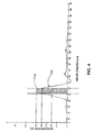
- Fig. 4 depicts a graph 750 of the optical absorbance of the polymer adhesive 612, i.e., the response detected by the EM detection device 720, as a function of wavelength.
- the cross-hatched area 760 under curve reveals the absorbance of the polymeric adhesive 612 in the short UV range.
- the amplitude of the response reaches a maximum value of about 0.6 on a scale of energy absorbance with an adhesive film thickness of 0.05mm using a Perkin Elmer Lambda 900 Spectrophotometer.
- the system controller 50 or a processor dedicated to the adhesive detection system 700, is operative to analyze the response of the EM energy detection device 720.
- the detection system 720 determines when the EM energy 750 emitted is below a threshold level signaling the absorbance of energy by the adhesive 612.
- the threshold level will generally be determined by a calibration step at system start-up, however, in the described embodiment, a threshold level of about 0.5 may be suitable for detecting the presence of adhesive on the substrate material 414.
- optical brighteners are often incorporated, or can be added, into the substrate material 414 such that the combined effect augments the effectiveness of the adhesive detection system 700. More specifically, such brighteners increase the signal that the EM detection device 720 receives.
- the Perkin Elmer Lambda 900 is equipped with an integrating sphere to collect all light from the sample.
- a content material detection system 100 comprising an imaging device 20 for optically imaging each of the wrapped envelopes 14 to determine the spatial relationship between the internal content material 414 and one or more points of reference indicative of the internal bounds of the sealing adhesive 612, a means for providing a cue when the spatial separation between the content material 414E and the point of reference 612E is less than a threshold value.
- the optical imaging system 20 includes a camera system 22 disposed on one side of a wrapped envelope 14 and a light source 26 disposed on the other side of the wrapped envelope 14.
- the camera system 33 captures two images of each wrapped envelope 14 while the envelope 14 is in motion.
- the two captured images are shown in Fig. 3 as the leading edge and trailing edge regions of interest LE ROI and TE ROI , respectively.
- the displacement of individual envelopes 14 are tracked along the feed path FP using conventional photocell event/encoder based means (not shown) enabling both images to be captured at the proper envelope locations to provide the two desired leading and trailing edge regions of interest, LE ROI , TE ROI .
- the exposure time for each image is sufficiently small to provide a clear, non-blurred image of the moving envelope 14.
- each leading edge and trailing edge regions of interest LE ROI and TE ROI contains a cut envelope edge 212E and a content material edge 412E, with margin on either side.
- the light source 26 is sufficiently bright to transmit sufficient light energy to transmit across or though two thicknesses of the wrap material 412 so that the camera system 22 can detect the transmitted light energy.
- An optical diffuser 28 may be employed over the light source 26 to produce more uniform light before passing through the envelope 14.
- the light source 26 is sufficiently bright to enable the use of a suitably high lens "f-stop", thereby providing an acceptable depth of field for envelopes of variable thickness.
- the light source 26 is strobed with the exposure of the camera 22, to allow a higher illumination intensity to transmit through variable envelope thicknesses.
- the content material 212 will decrease the amount of light transmitted such that the content material 212 will appear darker than the surrounding area, i.e., where the thickness of the wrapping material 414 is only two sheets in thickness.
- the algorithms determine the edge location of the content material 212E, the edge location of the envelope 412E (indicative of the edge location of the sealing adhesive 612E) and the separation distance therebetween. Examples of these separation distances are shown in Figure 3 as dimensions LE GAP and TE GAP . More specifically, the separation distance LE GAP ,TE GAP may be viewed as the difference between an actual value LL ACT , TL ACT indicative of the edge location of the content material and a predefined reference value LL MIN , TL MIN indicative of the edge location the sealing adhesive.
- the described embodiment uses an indirect point of reference, i.e., the edge location of the wrapped envelope. to define the location of the sealing adhesive, it should be appreciated that the location of the sealing adhesive may be used directly, to the extent that the imaging device 22 has the imaging power or resolution to do so.
- the values for LL MIN , TL MIN are predetermined for each mail run job and correspond to the distance between the envelope edge 414E and the inboard edge of the respective adhesive strip, i.e., glue line, If either LE GAP , or TE GAP , is less than the LL MIN or TL MIN , then the content material 212 either touches or interposes the sealing adhesive 612.
- the processor 50 determines that the spatial relationship does not meet certain predefined criteria, e.g., that the separation distance is below a threshold value, then a determination is made that the envelope 14 has not been properly wrapped. As a consequence, the envelope 14 is rejected and diverted from the feed path by an out-sort module 180.
- the edge detection algorithms must measure and determine the relative positions of the content material 212E relative to the predefined references associated with the wrapping material of the envelope 412E and/or the sealing adhesive 612E within a short period of time. That is, when the mailpiece fabrication system operates at full capacity, the content and wrapping materials 212, 414 travel at a rapid 70 cm/sec. While conventional edge detection algorithms can perform the requisite analysis and calculations within the available time period, the inventors learned that the use of certain security features know as "obfuscation patterns", present additional challenges for the content material detection system of the present invention. In the context used herein, obfuscation patterns refer to security features printed on the inside surface of a mailpiece to prevent the human eye from reading/viewing any internal print/images internal to the mailpiece.
- the preferred embodiment employs a light source 26 which emits electromagnetic energy at above about nine-hundred and twenty nanometers (920 nm) in wavelength and a long band-pass filter 24 which is compatible with the light source 28 over the lens of the camera 22 of the optical imaging device 20 nm.
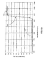
- Fig. 5a depicts a graph 190 of the optical characteristics of the long band-pass filler 24 wherein the filter 24 transmits ninety percent (90%) of the light energy in the region of the electromagnetic spectrum above about nine-hundred and twenty nanometers (920 nm) in wavelength and suppresses ninety-nine percent (99%) of the light energy below about eight hundred and fifty nanometers (850 nm) in wavelength.
- the use of these properties in connection with the optical imaging system 20 renders most obfuscation patterns ineffective and enhances the reliability of the inventive content material detection system 100.
- Another benefit to the use of this wavelength relates to the elimination of eye irritation which may be caused by strobing the high intensity light source 26. Additionally, the use of an infra-red light source 26 and long band-pass filter 24 prevents the imaging system 20 from detecting print on the outside surface of the wrapping material 412 and being mistakenly identified as an edge, i.e., of either the content or wrapping materials 212, 412.
- the detection system 100 may also be used in conjunction with the position control assembly 800 and used to dynamically adjust the phasing relationship between the collation 212 and the wrapping material 412.
- the content material 212 is merged with the wrapping material 412 at the open end of the tube-shaped wrap 412T while under the positional control of the phase nip roller assembly 810.
- the phase nip roller assembly 810 includes a drive roller 812 rotationally mounted to a pivot arm assembly 814 capable of rotational movement in the direction of arrows PA.
- the drive roller 812 is centered within the open end 4120 of the wrapping material 412.
- the roller 812 (i) receives the content material 212 from the upstream conveyor 280, (ii) drives each piece of content material 212 into one of a series of content material stations, i.e., each station defined by and between the sealing adhesive 612a, 612b, and (iii) matches the velocity of content material 212 with the that of the wrapping material 412.
- the phase nip roller 812 maintains control of the content material 212 by releasing the trailing edge of the content material 212 into one of the content material stations.
- a drive motor 816 drives the roller 812 in a counterclockwise direction while a linear actuator 820 releasably applies a downward force to effect engagement and release of the content material 212 into the open end 4120 of the wrapping system 300. While the drive motor 816 may drive the roller 812 using any one of a variety of drive mechanisms,, in the described embodiment, the roller 812 is driven by one or more drive belts (not shown) which wrap around the drive shaft of the roller 812.
- Phasing between the content material 212 and the wrapping material 412 is presently set with a job parameter.
- phasing is mean the timing and delivery of the content material 212 into the open end of the wrapping material 412 such that the content material is generally centered between successive strips of adhesive 612a, 612b and/or the envelope edges LE, TE which are cut downstream by the rotary cutter 336.
- This predefined position data is typically determined during set up of a specific job run using a trial and error method. After a mail run job is started, there are a number of matters that can cause the content material 212 to drift from a centered location inside the tube shaped wrapping material 412T. These include imperfect set of the job run, paper slippage at higher speeds, and elongation of the wrapping material 412 under high tensile loads.
- the position control system 800 therefore analyzes the output of the content material detection system 100, i.e., comparing the image data to the set of predefined position data, to produce a phase nip correction signal.
- the correction signal is used by the phase nip roller assembly 810 to adaptively adjust the position of the content material 212 by incrementally adjusting the he phase-nip roller assembly.
- the output of the leading and trailing edge gap values, LE GAP , TE GAP can be processed during machine runtime to fine tune the location/placement of the content material 212 to correct for content material 212 drift while still providing the out-sort capability for envelopes that fall below one of the threshold values.
- the use of a moving average of the leading and trailing edge gap values, LE GAP , TE GAP may be employed. After a first number of envelopes n, of a job run, the moving averages of the leading and trailing edge gap values, LE GAP , TE GAP are computed.
- the number n can be any value, e.g., one-hundred (100) envelopes where increasing the number will reduce the rate of change of the averages.
- the LE Moving Average will decrease and the TE Moving Average will increase. This results in a negative Phase Nip Correction Value, thereby shifting the content material 212 upstream with respect to the wrapping material 412, in a direction towards the nominal center of the tube-shaped wrap 412T. Similarly, as the content material 212 shifts upstream during a job, the Phase Nip Correction Value will become positive and will also shift the content material 212 towards the center of the wrapping material.
- the threshold values of LL MIN and TL MIN can still be used as threshold values for out-sorting envelopes that are considered to have poor content material 212 placement.
- the actual LE GAP and TE GAP values are less than these threshold values, i.e., LL MIN and TL MIN , it is preferred to discard them for use in the moving average calculations (Equations 1 and 2), as they fall outside the scope of acceptable envelopes 14 and should not adversely affect proper content material 212 placement.
- the envelope substrate material 414 is marked with cut quality marks.
- the envelope substrate material is typically continuous web of paper fed from a large spool. Predetermined segments of the paper web will be processed into separate envelopes, as described above.
- the continuous web can be pre-printed with envelope information such as addresses, logos, artwork, and the like.
- envelope information can be printed at a later stage, such as with printer 530.
- those marks must be printed prior to cutting, and are preferably pre-printed on the continuous web.
- Cut quality marks on the paper web are used as reference points to determine whether the proper segment of web has been cut to form an envelope.
- Mechanical irregularities in transport mechanisms and in the cutter 336 can cause the position of the cut to change relative to the folded tube 412T during operation of the system. If the cutter 336 blade cuts on a line of adhesive, the blade can become contaminated and the cutter will not work properly. Worse, if the cutter 336 cuts too far into an envelope 140, it could cut past the adhesive sealing line, and one end of the envelope can be left open completely. This would allow the contents to fall out during processing or at some later time.
- the cut quality marks can theoretically be at any position on an envelope. However, there will be other writing, markings, adhesive, and content materials that can interfere with the usefulness of the marks. Accordingly, in the preferred embodiment, the cut quality marks are positioned close to the leading and/or trailing edges of envelope where there are typically less marks or content material that might interfere. This preferred region is between the adhesive line and the lead or trailing edge, as depicted by TL MIN and LL MIN in Figs. 7 and 7A . In these Figures, exemplary cut quality marks 141, 142 and 141' and 142' are depicted.
- the marks 141 and 142 are positioned at the very edge of the envelope 140.
- a wider mark such as mark 143 in Fig. 3 , is cut in half upon execution of an optimal cut, leaving half of the mark on a trailing edge of a first envelope, and half on the leading edge of a subsequent envelope.
- the width of the mark 142 or 141 can be measured to determine whether the mark has been cut to the expected width.
- Fig. 7a shows an alternative embodiment showing marks 141' and 142' at respective positions that can also be measured in reference to the leading or trailing edge to determine whether the continuous web is in phase with the cutter 336.
- the cut quality marks 141, 142, etc. can be printed such that they will appear on the exterior or the interior of the envelopes when the envelope is folded and assembled. If the mark is on the exterior of the envelope then camera 100 will capture the image of the mark relative to the envelope edge. If the mark is on the interior of the envelope, then the light source 26 can project light through the envelope, such that the mark can be detected through the envelope, similar to the manner in which the light source 26 and camera 100 are used to detect mail piece contents, as described above.
- Fig. 8 An exemplary process flow for cut accuracy monitoring is shown in Fig. 8 .
- the individual envelopes 140 are cut by rotary knife 336 from the tube 412T of wrapping material on the continuous paper web.
- the envelope 140 is transported downstream to the camera 100.
- camera 100 is the same camera that is used to detect the position of the content within the envelope.
- the camera 100 scans the cut accuracy reference mark on the envelope.
- the image of the cut accuracy mark is provided to controller 50 where the reference dimensions of the mark are compared the expected dimensions (step 82).
- the reference mark 142 has been cut in half by the cut. Thus if the original mark was 5mm wide, the resulting cut mark should be 2.5mm wide.
- step 83 The difference between the measured dimension and the expected dimension is checked to determine whether a threshold tolerance is met. If cut accuracy is within tolerance, then operation can continue as normal. In step 84, if the difference is greater than the tolerance value, then some corrective action must be taken.
- the preferred corrective action is that defective envelopes are outsorted when they reach outsort module 180.
- the mailpiece fabrication system should be shut down to correct the problem.
- the difference between the expected and actual dimensions of the reference mark is continuously monitored and used in a feedback loop to constantly correct the positioning of the cut relative to the folded tube 412T of wrapping material.
- Known motion control feedback algorithms can be used to adjust the rotation of the rotary cutter 336, or the transport mechanism of the wrapping mechanism 300.
- the finishing modules may, inter alia, include a scale 510, a meter 520, a printer 520 and a tray or bin 530 for collecting the mailpieces.
- the scale 510 determines the weight of each mailpiece, but may also include a scanner to determine the size/volume of the mailpiece.
- a postage meter determines the postage required for delivery of the mailpiece.
- the printer 530 applies the postage indicia to the mailpiece and any other mailpiece information which may be required, e.g., destination and/or return address information.
- the mailpieces may be accumulated in a tray or bin for ease of delivery.
Landscapes
- Engineering & Computer Science (AREA)
- Mechanical Engineering (AREA)
- Making Paper Articles (AREA)
Abstract
Description
- The present invention relates to mailpiece fabrication systems, and, more particularly, to a method and system for ensuring cutting accuracy when separating individual envelopes.
- Mailpiece fabrication systems such as mailpiece inserters and mailpiece wrappers are typically used by organizations such as banks, insurance companies, and utility companies to periodically produce a large volume of mail, e.g., monthly billing or shareholders income/dividend statements. In many respects, mailpiece inserters are analogous to automated assembly equipment inasmuch as sheets, inserts and envelopes are conveyed along a feed path and assembled in, or at, various modules of the mailpiece inserter. That is, the various modules work cooperatively to process the sheets until a finished mailpiece is produced.
- Mailpiece inserters include a variety of apparatus/modules for conveying and processing a substrate/sheet material along the feed path. Commonly mailpiece inserters include apparatus/modules for (i) feeding and singulating printed content in a "feeder module", (ii) accumulating the content to form a multi-sheet collation in an "accumulator", (iii) folding the content to produce a variety of fold configurations such as a C-fold, Z-fold, bi-fold and gate fold, in a "folder", (iv) feeding mailpiece inserts such as coupons, brochures, and pamphlets, in combination with the content, in a "chassis module" (v) inserting the folded/unfold and/or nested content into an envelope in an "envelope inserter", (vi) sealing the filled envelope in "sealing module" and (vii) printing recipient/return addresses and/or postage indicia on the face of the mailpiece envelope at a "print station".
- In lieu of modules for inserting and/or sealing the content material into an "envelope", some mailpiece fabrication systems employ a wrapping system operative to encapsulate the mailpiece content in an outer wrapping material or substrate. Therein, the content material is fed into a substrate/wrap having a pressure-activated adhesive deposited thereon to enclose/seal the content material in a tubular-shaped envelope wrap. More specifically, the content material is fed into a wrapping module which receives a supply of substrate material from a web of rolled material. Before being fed to the wrapping module, an adhesive application module deposits a polymeric adhesive in a predefined two-dimensional pattern on the substrate material. As the substrate material is folded by the wrapping system, an envelope pocket is produced for receipt of the content material.
- More specifically, the supply of substrate material is fed from beneath the deck of the wrapping module and turned downstream to define an open-end for accepting a supply of content material. As the substrate and content material is pulled downstream, a one or more guides fold the substrate material inwardly such that the outboard edge portions overlap. Furthermore, a tube-shaped wrap is produced around the content material as the substrate material is drawn together downstream of the open end. The content-filled tubular structure then is passed under a series of pressure rollers to cause the pressure-activated adhesive to form a series of individual pockets having content material in each. Thereafter, the wrapping module includes a cutting roller to separate the content-filled pockets into separate envelopes.
- To obtain the throughput advantages of a mailpiece fabrication system, and especially one employing a wrapping system, it is important to maintain the reliability and minimize the downtime of the fabrication system. While a variety of mailpiece fabrication errors can occur to adversely impact throughput, one of the more frequent sources originates from the handling apparatus of the wrapping module. More specifically, difficulties arise when placing the content material into the open end of the tube-shaped wrap such that the content material is placed into and remains at the proper location relative to adhesive deposited along the peripheral edges of the mailpiece.
- A further difficulty can arise if the cutting mechanism for separating the individual envelopes gets out of phase with the continuous web of envelope material. After the wrapping material is folded and sealed around the content material, the individual envelopes are cut. If the web is out of position with the cutter, then the cutter might come into contact with glue used to seal the envelopes. It is also possible that the envelope could be cut such that a seal is completely cut off one end of the envelope, and the contents are free to fall out.
- A need, therefore, exists for a system for detecting cutting position errors and dynamically adjusting the cutting position of the web material.
- An improved mailpiece fabrication system and method are provided for assembling finished envelopes from content materials and from wrapping materials. The wrapping materials are comprised of a continuous web of printed substrate, (preferably paper). The printed paper web includes printed envelope information and cut quality marks for individual envelopes.
- The system includes a conveyance deck upon which the continuous web is transported while content materials are placed on the continuous web. The continuous web is then folded around the content materials to form a continuous tube enclosing the content materials. A cutter downstream of the conveyance deck cuts individual envelopes from the continuous tube of folded wrapping material.
- An imaging device is positioned downstream of the cutter to optically image each of the individual envelopes. The imaging device captures image data indicative of a cut quality mark on the individual envelopes. A controller receives image data from the imaging device and compares an actual dimension of an imaged cut quality mark with an expected dimension of a cut quality mark. An error signal is produced if the difference is not within a predetermined tolerance.
- The system preferably includes an outsort station downstream of the imaging device. The controller causes defective envelopes to be outsorted in response to the error signal.
- The controller may also provide feedback signals to correct any error to the cutting position. That feedback can be used to adjust the cutter speed and/or the speed of the upstream continuous web transport.
- In the preferred embodiment, the cut quality marks are positioned on the envelope cut lines of the continuous web. Thus, when a successful envelope cut is made, the marks will be cut in half, with half of the mark on the trail edge of a first envelope and the leading edge of a second envelope. In that embodiment, the width of the cut quality mark is used as the measure for determining whether the envelope has been cut properly.
- The cut mark can be on an outer surface or inner surface of the assembled envelope. When the mark is on the interior of the envelope, the optical imaging device includes a light source disposed on one side of the wrapped envelope. A light imaging camera is positioned on the opposite side of the wrapped envelope to receive light transmitted through the wrapped envelope and to determine the position of the mark therein. The light source may be strobed in time with the light imaging camera.
- The accompanying drawings illustrate presently preferred embodiments of the invention and, together with the general description given above and the detailed description given below serve to explain the principles of the invention. As shown throughout the drawings, like reference numerals designate like or corresponding parts.
-
Figure 1 is a schematic top view of a mailpiece fabrication system including content fabrication modules, wrapping material preparation modules including an adhesive application and detection system, a wrapping system, content material detection and position control modules and a plurality of finishing modules. -
Figure 2 is an enlarged schematic top view of the relevant portions of the mailpiece fabrication system according to the present invention including a wrapping system and a content material detection and position control system of the present invention. -
Figure 3 is a broken-away perspective view of an adhesive application and detection system disposed on opposing surfaces of a mailpiece wrapping material. -
Figure 4 is a graphical depiction of the absorbance of a polymer adhesive as a function of wavelength from zero to one-thousand nanometers (0nm -1000 nm) in wavelength. -
Figure 5 is a broken-away perspective view of the content material detection system according one embodiment of the invention an optical imaging system for determining the spatial relationship of the content material relative to the overlying wrapping material. -
Figure 5a is a graphical depiction of the transmission characteristics (i.e., the percent transmission vs. wavelength in nanometers (nm)) of a high pass filter used in conjunction with the optical imaging system of the content material detection system. -
Figure 6 is a broken-away perspective view of the content material detection system according to another embodiment of the invention which employs feedback from the content material detection system to incrementally adjust the longitudinal position of the content material relative to the wrapping material. -
Figure 7 and 7a are exemplary individual envelopes that have been printed and assembled to include cut quality marks. -
Figure 8 is a process flow diagram showing exemplary steps for using the cut quality marks to improve mailpiece fabrication quality and performance. - While the invention is described in the context of a paper-based wrapping system, i.e., a system which is fed by a paper web, for creating finished mailpieces, the invention is equally applicable to other mailpiece fabrication systems wherein adhesive is applied to a substrate material used to produce an envelope. Consequently, the detailed description and illustrations are merely indicative of an embodiment of the invention, and, accordingly, the invention should be broadly interpreted in accordance with the appended claims.
- Before discussing some of the more relevant details of the system and method of the present invention, a brief overview of a mailpiece fabrication system will be provided.
Figs. 1 and2 depict a schematic block diagram of amailpiece fabrication system 10 according to the present invention wherein: (i) a supply ofcontent material 212 is produced by a variety of upstreamcontent fabrication modules 200, (ii) awrapping system 300 receives a supply of wrappingmaterial 412, i.e., from a plurality of wrappingmaterial preparation modules 400, and (iii) a plurality offinishing modules 500 complete the mailpiece fabrication process including weighing, metering and printing postage indicia on each wrapped envelope. Before the supply of wrappingmaterial 412 is conveyed to thewrapping system 300, anadhesive application system 600 andadhesive detection system 700 prepare thesubstrate material 414 for being wrapped/sealed around thecontent material 212. More specifically, theadhesive application system 600 deposits a sealing adhesive 612 (seeFig. 3 ) about the periphery of theenvelope 14 to wrap and enclosecontent material 212 therein. - The output of the
wrapping system 300 is a series of wrappedenvelopes 14 which, if properly wrapped, proceed to thefinishing modules 500 where delivery data such as a mailpiece destination/return address is added. According to one embodiment of the invention, a contentmaterial detection system 100 is provided to examine the spatial relationship of thecontent material 212 to the sealingadhesive 612 to determine if the content material has been properly wrapped. According to another embodiment of the invention, aposition control system 800 is provided to adaptively control the position of thecontent material 212 relative to the sealingadhesive 612 for the purpose of ensuring the efficacy of the peripheral seal and output efficiency of thewrapping system 300. - The overall operation of the
mailpiece fabrication system 10 is coordinated, monitored and controlled by asystem controller 50. While themailpiece fabrication system 10 is described and illustrated as being controlled by a single system processor/controller 50, it should be appreciated that each of the modules 100 - 600 may be individually controlled by one or more processors. Hence, thesystem controller 50 may also be viewed being controlled by one or more individual microprocessors. - In the described embodiment, the upstream
content fabrication modules 200 include afeeder 210 containing astack 214 of pre-printed sheets ofcontent material 212. The pre-printed sheets ofcontent material 212 are separated in thefeeder 210 by asingulating apparatus 216 which uses a combination ofguides 217,drive belts 218, and astone roller 219 to retard the upper portion of thestack 212 while the lowermost sheet in thestack 212 is "singulated" or separated from the underside of thestack 212. - Next, the
content material 212 is conveyed to ascanner 220 which reads information contained on select sheets of thecontent material 212 to provide mailpiece processing information to thecontroller 50. For example, a Beginning Of Collation (BOC)mark 222 may be read by ascanner 224 to indicate which sheet ofcontent material 212, in a series of sheets being conveyed along a feed path FP, is the first sheet of a collation. Thesemarks 222, also known as scan codes, are typically located in the margins of thecontent material 212 and are used to provide a myriad of information relating to the subsequent processing of thecontent material 212. -
Scan codes 222 can provide information regarding whether a particular collation is to be folded, stitched, or stapled. Alternatively, a scan code can provide information regarding whether a particular mailpiece insert will be added to a particular sheet ofcontent material 212 or to a collation of sheets ofcontent material 212. Additionally, the scan code can provide information regarding the type of mailpiece being fabricated, i.e., whether the content material contains sensitive or confidential information. For example, somecontent material 212 may contain a recipient's social security number, credit card account information or private health information (protected under the HIPPA laws). - Once scanned, the sheets of
content material 212 may then be grouped in anaccumulator module 230 to produce a stacked collation ofcontent material 212. A collation is typically produced by retarding the motion of select sheets in apocket 232 of theaccumulator module 230. Accordingly, the large stack ofpre-printed sheets 212 which was singulated upstream by thefeeder 210 may now be grouped together in smaller stacks to form one or more collations. - The
content material 212, whether stacked into a collation or remaining as a single sheet, may be conveyed to afolding module 240 operative to fold the content material into a particular fold configuration. More specifically, thefolding module 240 manipulates the content material around a plurality ofpress rollers 242 to produce various fold configurations, e.g., a bi-fold, C-fold, Z-fold or gate-fold configuration. Depending upon the processing information obtained from thescan codes 222, thefold module 240 may introduce a fold configuration into thecontent material 212 or pass thecontent material 212 unaffected to achassis module 250. - The
chassis module 250 performs one of the more important functions of thecontent fabrication modules 200 inasmuch a variety of additional information can be added to thecontent material 212 by way of mailpiece inserts 252, e.g., coupons, advertisements, solicitations, etc. Therein, amailpiece insert 252 may be added by one of a series ofoverhead feeders content material 212 as it passes beneath theoverhead feeders system controller 50 knows the specific processing requirements and location of each piece ofcontent material 212, i.e., location along the feed path, theoverhead feeders content material 212 for a particular mailpiece recipient.. For example, a specific advertisement, targeted to one mailpiece recipient, may be added by one of thefeeders content material 212 of another mailpiece recipient by another of thefeeders - The
content material 212 is then passed to a buffer module 270 through a right angle turn module (RAT) 260. Depending upon the space available for the various upstreamcontent fabrication modules 200, the RAT 260 may, or may not, be required. The buffer module 270, on the other hand, performs another one of the more critical operations inasmuch as it serves as the "traffic manager" for themailpiece fabrication system 10. More specifically, the buffer module 270 employs one (1) in-feed buffer gate G0 and five (5) buffer gates G1 - G5 to coordinate the timing of thecontent material 212 from thechassis module 250 to thewrapping system 300. Such coordination is necessary to eliminate gaps or "dry-holes" when deliveringcontent material 212 to thewrapping system 300. - In operation, the buffer module 270 receives input from the
controller 50 regarding the flow ofcontent material 212 from thechassis module 250 and determines the requisite speed of thewrapping system 300 to ensure that the supply ofcontent material 212 is smooth and uninterrupted. Based upon the anticipated acceleration of thewrapping system 300, the controller invokes various algorithms to ensure that thewrapping system 300 is not exposed to accelerations which may rupture, tear or fail the supply of wrappingmaterial 412. As a result reliability and throughput of themailpiece fabrication system 10 is optimized. - In addition to optimizing throughput, the buffer module 270 ensures that
content material 212 is properly "matched" with a supply of pre-printed wrapping material 312 and the resulting wrapped envelope contains the content material for which it was intended. - From the buffer module 270, the content material is passed to an
input conveyor 280 at a right-angle for delivery to thewrapping system 300. Theinput conveyor 280 is conventional in its construction and includes pairs of drive fingers 282 which are driven by belts (also not shown) throughelongate slots 284 in atransport deck 286. The drive fingers 282 engage a trailing edge of thecontent material 212 to convey the content material along the deck 285. To prevent the sudden impact of the fingers 282 from disrupting the registration of thecontent material 212, theinput conveyor 280 includes a pair of drive rollers (not shown) to accelerate thecontent material 212 before being acted on by the drive fingers 282. That is, the drive rollers are operative to accelerate thecontent material 212 such that the drive fingers 282 engage the trailing edge at nearly the same speed/velocity as thecontent material 212. As such, a smooth transition occurs to prevent misalignment of thecontent material 212, e.g., a collation of sheets including one or more inserts, upon changing direction and velocity. - The
content material 212 is then conveyed downstream to a phase niproller assembly 810, which according to the present invention, is a component of theposition control system 800, and functions to deliver thecontent material 212 to thewrapping system 300. More specifically, the phase niproller 810 centers and matches the velocity of thecontent material 212 relative to the supply of wrappingmaterial 412. It should be appreciated that the delivery ofcontent material 212 from thecontent fabrication modules 200 to thewrapping system 300 is a critical to the workings of themailpiece fabrication system 10. The control and timing thereof is discussed in greater detail below in a section entitled "Content Material Detection and Position Control Systems". - In
Fig. 2 , thewrapping system 300 receives content material from theinput conveyor 280 and phase niproller 810 of theposition control system 800. Furthermore, thewrapping system 300 receives wrappingmaterial 412 from the wrappingmaterial preparation modules 400. With respect to the latter, prepared wrappingmaterial 412 is fed to anupper conveyance deck 306 of thewrapping system 300 from a series ofrollers 308 disposed beneath thedeck 306. By "prepared" is meant that the wrappingmaterial 300 may have address or advertisement information pre-printed on a face of the wrapping material. Furthermore, the wrappingmaterial 300 may pre-cut to a particular envelope configuration, i.e., including windows for viewing internal information printed on the wrapped content material, and/or have adhesive deposited in select areas. - The wrapping
material 412 is drawn vertically upward (i.e., normal to the plane of the conveyance deck 306), across anupstream edge 310 of thedeck 306 and horizontally downstream, i.e., in the direction of arrow FD, along the surface of theconveyance deck 306. As the wrappingmaterial 412 is drawn over theupstream edge 310, theoutboard edge portions 4120 of the wrappingmaterial 412 are pulled across a pair ofguide rods 320 such that theoutboard edge portions 4120 converge at a point P and overlap. As such, the wrappingmaterial 412 produces an "open-end" for accepting thecontent material 212 from the phase niproller 810. Furthermore, a tube-shapedwrap 412T is formed around thecontent material 212 as the wrappingmaterial 412 is drawn together downstream of the open-end. - In the described embodiment, several pieces of
content material 212 have been laid into the open end of the tube-shapedwrapping material 412T and spaced-apart by a pitch distance PI, i.e., the distance from the leading edge of one piece ofcontent material 212a to the leading edge of the subsequent piece ofcontent material 212b. Once wrapped, the tube-shaped wrapping materia1412T is compressed by a triage ofpress rollers 330 to produce astrip 412S of sealed mailpiece envelopes. The strip 414S of sealed mailpiece envelopes is then is cut to produce individual wrappedenvelopes 14 by arotary cutter 336. - Thereafter, each of the wrapped
envelopes 14 is transported from therotary cutter 336 on avacuum deck 338 which is controlled to separate each wrappedenvelope 14 by a predetermined separation distance. Once again, the distance between successive leading edges is the pitch distance PI of the wrappedenvelopes 14. - In
Fig. 2 , the supply of wrappingmaterial 412 is prepared as a flat-pattern substrate which is rolled into a web ofsubstrate material 414. The flat pattern substrate may include pre-printed information such as recipient and sender address information (not shown) or may be pre-cut to include windows (also not shown) for viewing mailpiece address information printed on thecontent material 212. - In the described embodiment, the
substrate material 414 is conveyed over a series ofre-directing rollers 308 which direct thesubstrate material 414 downwardly passed anadhesive application system 600 and upwardly toward the deck 306 (seeFig. 1 ) of thewrapping system 300. Theadhesive application system 600 includes a bank ofapplication nozzles 610 for depositing a thin line/film of adhesive 612 on thesubstrate material 414 as it moves passed each of thenozzles 610. A supply of the adhesive 612 is contained in apressure vessel 616 for feeding each of theapplication nozzles 610. Thevessel 616 is heated to a temperature of about two hundred degrees Fahrenheit (200°F) by a conventionalelectric heating element 618 and pressurized to an internal pressure of about between about thirty to ninety PSI (30 - 90 lb/in2) by ahydraulic pump 620. - Additionally, the
application nozzles 610 are mounted to acarriage assembly 626 which moves toward or away from thesubstrate material 414 in the direction of arrows NM by alinear actuator 628. More specifically, theapplication nozzles 610 are mounted to cross-member 632 bearing mounted to a pair of guide rails 636. Furthermore, the guide rails 636 are orthogonal to and disposed beneath there-directing rollers 308. - Each time the
wrapping system 300 demands a supply of wrappingmaterial 412, thelinear actuator 628 moves the bank ofapplication nozzles 610 toward thesubstrate material 414 to deposit adhesive 612. The deposition of adhesive can be as straightforward as depositing a line of a predetermined thickness on thesubstrate material 414 as the substrate is conveyed across the head of eachnozzles 610. Generally, the lines of adhesive 612 run parallel or orthogonal to the feed path FP of thesubstrate material 414. The gaps or breaks in the lines of adhesive 612 are predefined by the mail run data, i.e., the file containing mailpiece fabrication data, and made to effect a particular seal configuration when the wrappingmaterial 414 is folded and cut by thewrapping system 300. Consequently, the gaps and breaks are fixed, i.e., the spacing therebetween are generally constant. - Notwithstanding the conventional manner for depositing adhesive 612, commonly owned, co-pending patent application entitled "Adaptive Adhesive Application (AAA) System", discloses an
adhesive application system 100 which is variable to improve reliability and reduce the maintenance required in connection with thewrapping system 300 and other modules 100 - 800. More specifically, in the co-pending AAA System, the inventors discovered that by selectively controlling thenozzles 610, and the process for depositing the adhesive, cross-contamination to other modules, e.g., therotary cutter 336, can be significantly reduced. - Irrespective the requirement to control the flow of adhesive as described in the preceding paragraph, there is still a need to determine if the adhesive has been properly applied. For example, should the lack of adhesive prevent closure of the envelope, there is a chance that hundreds of
envelopes 14 may be improperly sealed. While the lack of forming a proper enclosure may be relatively inconsequential for someenvelopes 14, for others containing confidential information, e.g., a social security number, credit card number or bank account information, the legal liabilities can be significant for the mailer. - In the described embodiment and referring to
Figs. 2 and3 , anadhesive detection system 700 determines whether the adhesive 612 was: (i) applied to thesubstrate material 414, (ii) applied at the proper location, and/or (iii) was applied in the proper quantity. Thesystem 700 comprises a source 110 of ElectroMagnetic (EM)energy 712, in at least the short UV range, to illuminate thesurface 414s of thesubstrate material 414, i.e.,select regions 616 where the adhesive 612 is anticipated to be deposited. A source ofEM energy 712 suitable for irradiating thesurface 414s with UV light may be a short UV Light Emitting Diode (LED) or series short UV LEDs. Furthermore, a fluorescent UVC germicidal lamp may be used to illuminate thesubstrate 414. Any known illumination can be used, such as, UV lasers, as long as they emit EM energy in the short UV range. By "short UV" range means between one-hundred (100nm) to about three-hundred nanometers (300 nm). Preferably still, a short UV range means between two-hundred forty nanometers (240 nm) to about two-hundred eighty nanometers (280 nm). - The wrapping material or
substrate 414 is a conventional fiber reinforced, resin impregnated white paper which, when irradiated with short UVC energy, emits or fluoresces EM energy in the visible light range (i.e., a higher wavelength) of between about four-hundred nanometers (400 nm) to eight hundred nanometers (800 nm). While the wrappingmaterial 414 emits energy in the visible light range when irradiated with short UVC energy, thepolymeric adhesive 612 absorbs the most or all of the UVC energy. Consequently, thepolymeric adhesive 612 can be viewed as blocking the UV energy from reaching theunderlying substrate material 414. - Additionally, the
system 700 includes an EMenergy detection device 720 operative to detectenergy 722 reflected from thesurface 414s of thesubstrate material 414 in the visible light range of between about four-hundred nanometers (400 nm) to eight hundred nanometers (800 nm). AnEM detection device 720 suitable for practicing the invention includes a light-to-voltage sensor used to collect the light emitted from thesubstrate 414 and convert the light to an analog voltage. Any other energy detection methods can be used such as, a photocathode or a CCD/Vision system. -
Fig. 4 depicts agraph 750 of the optical absorbance of thepolymer adhesive 612, i.e., the response detected by theEM detection device 720, as a function of wavelength. The cross-hatched area 760 under curve reveals the absorbance of thepolymeric adhesive 612 in the short UV range. In the described embodiment, the amplitude of the response reaches a maximum value of about 0.6 on a scale of energy absorbance with an adhesive film thickness of 0.05mm using a Perkin Elmer Lambda 900 Spectrophotometer. - The
system controller 50, or a processor dedicated to theadhesive detection system 700, is operative to analyze the response of the EMenergy detection device 720. Thedetection system 720 determines when theEM energy 750 emitted is below a threshold level signaling the absorbance of energy by the adhesive 612. The threshold level will generally be determined by a calibration step at system start-up, however, in the described embodiment, a threshold level of about 0.5 may be suitable for detecting the presence of adhesive on thesubstrate material 414. - To facilitate detection, optical brighteners are often incorporated, or can be added, into the
substrate material 414 such that the combined effect augments the effectiveness of theadhesive detection system 700. More specifically, such brighteners increase the signal that theEM detection device 720 receives. The Perkin Elmer Lambda 900, is equipped with an integrating sphere to collect all light from the sample. - In addition to a
system 700 which detects the presence, location and quantity of adhesive 612 on thesubstrate material 414, the present invention monitors the efficacy, reliability and output of the wrapping system. InFig. 5 , a contentmaterial detection system 100 is provided comprising animaging device 20 for optically imaging each of the wrappedenvelopes 14 to determine the spatial relationship between theinternal content material 414 and one or more points of reference indicative of the internal bounds of the sealing adhesive 612, a means for providing a cue when the spatial separation between the content material 414E and the point ofreference 612E is less than a threshold value. - More specifically, the
optical imaging system 20 includes acamera system 22 disposed on one side of a wrappedenvelope 14 and alight source 26 disposed on the other side of the wrappedenvelope 14. The camera system 33 captures two images of each wrappedenvelope 14 while theenvelope 14 is in motion. The two captured images are shown inFig. 3 as the leading edge and trailing edge regions of interest LEROI and TEROI, respectively. The displacement ofindividual envelopes 14 are tracked along the feed path FP using conventional photocell event/encoder based means (not shown) enabling both images to be captured at the proper envelope locations to provide the two desired leading and trailing edge regions of interest, LEROI, TEROI. The exposure time for each image is sufficiently small to provide a clear, non-blurred image of the movingenvelope 14. Ideally, each leading edge and trailing edge regions of interest LEROI and TEROI, contains acut envelope edge 212E and acontent material edge 412E, with margin on either side. - The
light source 26 is sufficiently bright to transmit sufficient light energy to transmit across or though two thicknesses of thewrap material 412 so that thecamera system 22 can detect the transmitted light energy. Anoptical diffuser 28 may be employed over thelight source 26 to produce more uniform light before passing through theenvelope 14. Additionally, thelight source 26 is sufficiently bright to enable the use of a suitably high lens "f-stop", thereby providing an acceptable depth of field for envelopes of variable thickness. In a preferred embodiment, thelight source 26 is strobed with the exposure of thecamera 22, to allow a higher illumination intensity to transmit through variable envelope thicknesses. Within the region of interest (ROI), thecontent material 212 will decrease the amount of light transmitted such that thecontent material 212 will appear darker than the surrounding area, i.e., where the thickness of the wrappingmaterial 414 is only two sheets in thickness. - Once the
camera 26 captures and stores an image (i.e., commonly referred to as frame grabbing), conventional edge detection algorithms process the digital image data. In the described embodiment, the algorithms determine the edge location of thecontent material 212E, the edge location of theenvelope 412E (indicative of the edge location of the sealing adhesive 612E) and the separation distance therebetween. Examples of these separation distances are shown inFigure 3 as dimensions LEGAP and TEGAP. More specifically, the separation distance LEGAP,TEGAP may be viewed as the difference between an actual value LLACT, TLACT indicative of the edge location of the content material and a predefined reference value LLMIN, TLMIN indicative of the edge location the sealing adhesive. While the described embodiment uses an indirect point of reference, i.e., the edge location of the wrapped envelope. to define the location of the sealing adhesive, it should be appreciated that the location of the sealing adhesive may be used directly, to the extent that theimaging device 22 has the imaging power or resolution to do so. - As mentioned in the preceding paragraph, the values for LLMIN, TLMIN are predetermined for each mail run job and correspond to the distance between the envelope edge 414E and the inboard edge of the respective adhesive strip, i.e., glue line, If either LEGAP, or TEGAP, is less than the LLMIN or TLMIN, then the
content material 212 either touches or interposes the sealingadhesive 612. When theprocessor 50 determines that the spatial relationship does not meet certain predefined criteria, e.g., that the separation distance is below a threshold value, then a determination is made that theenvelope 14 has not been properly wrapped. As a consequence, theenvelope 14 is rejected and diverted from the feed path by an out-sort module 180. - The edge detection algorithms must measure and determine the relative positions of the
content material 212E relative to the predefined references associated with the wrapping material of theenvelope 412E and/or the sealing adhesive 612E within a short period of time. That is, when the mailpiece fabrication system operates at full capacity, the content and wrappingmaterials - Inasmuch as typical obfuscation patterns absorb light in the visible spectrum to prevent viewing by a human eye, these patterns are far less effective in the near-infrared region of the electromagnetic (EM) spectrum above about 920 nm in wavelength. To facilitate the continued use of conventional obfuscation patterns on wrapping material, the preferred embodiment employs a
light source 26 which emits electromagnetic energy at above about nine-hundred and twenty nanometers (920 nm) in wavelength and a long band-pass filter 24 which is compatible with thelight source 28 over the lens of thecamera 22 of theoptical imaging device 20 nm. -
Fig. 5a depicts agraph 190 of the optical characteristics of the long band-pass filler 24 wherein thefilter 24 transmits ninety percent (90%) of the light energy in the region of the electromagnetic spectrum above about nine-hundred and twenty nanometers (920 nm) in wavelength and suppresses ninety-nine percent (99%) of the light energy below about eight hundred and fifty nanometers (850 nm) in wavelength. The use of these properties in connection with theoptical imaging system 20 renders most obfuscation patterns ineffective and enhances the reliability of the inventive contentmaterial detection system 100. - Another benefit to the use of this wavelength relates to the elimination of eye irritation which may be caused by strobing the high intensity
light source 26. Additionally, the use of an infra-red light source 26 and long band-pass filter 24 prevents theimaging system 20 from detecting print on the outside surface of the wrappingmaterial 412 and being mistakenly identified as an edge, i.e., of either the content or wrappingmaterials - The
detection system 100 may also be used in conjunction with theposition control assembly 800 and used to dynamically adjust the phasing relationship between thecollation 212 and the wrappingmaterial 412. InFig. 6 , thecontent material 212 is merged with the wrappingmaterial 412 at the open end of the tube-shapedwrap 412T while under the positional control of the phase niproller assembly 810. As thecontent material 212 approaches thewrapping system 300, it is travelling at a higher velocity than the wrappingmaterial 412. The phase niproller assembly 810 includes adrive roller 812 rotationally mounted to apivot arm assembly 814 capable of rotational movement in the direction of arrows PA. Furthermore, thedrive roller 812 is centered within theopen end 4120 of the wrappingmaterial 412. The roller 812 (i) receives thecontent material 212 from theupstream conveyor 280, (ii) drives each piece ofcontent material 212 into one of a series of content material stations, i.e., each station defined by and between the sealing adhesive 612a, 612b, and (iii) matches the velocity ofcontent material 212 with the that of the wrappingmaterial 412. The phase niproller 812 maintains control of thecontent material 212 by releasing the trailing edge of thecontent material 212 into one of the content material stations. More specifically, adrive motor 816 drives theroller 812 in a counterclockwise direction while a linear actuator 820 releasably applies a downward force to effect engagement and release of thecontent material 212 into theopen end 4120 of thewrapping system 300. While thedrive motor 816 may drive theroller 812 using any one of a variety of drive mechanisms,, in the described embodiment, theroller 812 is driven by one or more drive belts (not shown) which wrap around the drive shaft of theroller 812. - Phasing between the
content material 212 and the wrappingmaterial 412 is presently set with a job parameter. By "phasing" is mean the timing and delivery of thecontent material 212 into the open end of the wrappingmaterial 412 such that the content material is generally centered between successive strips of adhesive 612a, 612b and/or the envelope edges LE, TE which are cut downstream by therotary cutter 336. This predefined position data is typically determined during set up of a specific job run using a trial and error method. After a mail run job is started, there are a number of matters that can cause thecontent material 212 to drift from a centered location inside the tube shaped wrappingmaterial 412T. These include imperfect set of the job run, paper slippage at higher speeds, and elongation of the wrappingmaterial 412 under high tensile loads. - The
position control system 800, therefore analyzes the output of the contentmaterial detection system 100, i.e., comparing the image data to the set of predefined position data, to produce a phase nip correction signal. The correction signal is used by the phase niproller assembly 810 to adaptively adjust the position of thecontent material 212 by incrementally adjusting the he phase-nip roller assembly. - The output of the leading and trailing edge gap values, LEGAP, TEGAP can be processed during machine runtime to fine tune the location/placement of the
content material 212 to correct forcontent material 212 drift while still providing the out-sort capability for envelopes that fall below one of the threshold values. For example in one implementation of the method, the use of a moving average of the leading and trailing edge gap values, LEGAP, TEGAP, may be employed. After a first number of envelopes n, of a job run, the moving averages of the leading and trailing edge gap values, LEGAP, TEGAP are computed. The number n, can be any value, e.g., one-hundred (100) envelopes where increasing the number will reduce the rate of change of the averages. Based on the moving averages, the phase parameter can be corrected by a small amount. Thereafter, a new moving average is computed for each envelope and the phase nip correction value can be computed as follows:


- Therefore as the
content material 212 shifts downstream during a job fun the LE Moving Average will decrease and the TE Moving Average will increase. This results in a negative Phase Nip Correction Value, thereby shifting thecontent material 212 upstream with respect to thewrapping material 412, in a direction towards the nominal center of the tube-shapedwrap 412T. Similarly, as thecontent material 212 shifts upstream during a job, the Phase Nip Correction Value will become positive and will also shift thecontent material 212 towards the center of the wrapping material. - Since this method always effects a shift of the
content material 212 towards the center of the tube-shapedwrap 412T, the threshold values of LLMIN and TLMIN can still be used as threshold values for out-sorting envelopes that are considered to havepoor content material 212 placement. When the actual LEGAP and TEGAP values are less than these threshold values, i.e., LLMIN and TLMIN, it is preferred to discard them for use in the moving average calculations (Equations 1 and 2), as they fall outside the scope ofacceptable envelopes 14 and should not adversely affectproper content material 212 placement. - In accordance with the preferred embodiment, the
envelope substrate material 414 is marked with cut quality marks. The envelope substrate material is typically continuous web of paper fed from a large spool. Predetermined segments of the paper web will be processed into separate envelopes, as described above. - The continuous web can be pre-printed with envelope information such as addresses, logos, artwork, and the like. Alternatively, envelope information can be printed at a later stage, such as with
printer 530. However, for purposes of cut quality marks, those marks must be printed prior to cutting, and are preferably pre-printed on the continuous web. - Cut quality marks on the paper web are used as reference points to determine whether the proper segment of web has been cut to form an envelope. Mechanical irregularities in transport mechanisms and in the
cutter 336 can cause the position of the cut to change relative to the foldedtube 412T during operation of the system. If thecutter 336 blade cuts on a line of adhesive, the blade can become contaminated and the cutter will not work properly. Worse, if thecutter 336 cuts too far into anenvelope 140, it could cut past the adhesive sealing line, and one end of the envelope can be left open completely. This would allow the contents to fall out during processing or at some later time. - The cut quality marks can theoretically be at any position on an envelope. However, there will be other writing, markings, adhesive, and content materials that can interfere with the usefulness of the marks. Accordingly, in the preferred embodiment, the cut quality marks are positioned close to the leading and/or trailing edges of envelope where there are typically less marks or content material that might interfere. This preferred region is between the adhesive line and the lead or trailing edge, as depicted by TLMIN and LLMIN in
Figs. 7 and 7A . In these Figures, exemplary cut quality marks 141, 142 and 141' and 142' are depicted. - In the preferred embodiment shown in
Fig. 7 themarks envelope 140. In this embodiment, a wider mark, such asmark 143 inFig. 3 , is cut in half upon execution of an optimal cut, leaving half of the mark on a trailing edge of a first envelope, and half on the leading edge of a subsequent envelope. In this embodiment, the width of themark -
Fig. 7a shows an alternative embodiment showing marks 141' and 142' at respective positions that can also be measured in reference to the leading or trailing edge to determine whether the continuous web is in phase with thecutter 336. As seen in the example shown inFig. 3 , there are twomarks 143 of known width that are positioned at each boundary of the respective envelope sheets such that the marks will be cut in half by an accurate cut. - For all of these examples, the cut quality marks 141, 142, etc. can be printed such that they will appear on the exterior or the interior of the envelopes when the envelope is folded and assembled. If the mark is on the exterior of the envelope then
camera 100 will capture the image of the mark relative to the envelope edge. If the mark is on the interior of the envelope, then thelight source 26 can project light through the envelope, such that the mark can be detected through the envelope, similar to the manner in which thelight source 26 andcamera 100 are used to detect mail piece contents, as described above. - An exemplary process flow for cut accuracy monitoring is shown in
Fig. 8 . Atstep 80 theindividual envelopes 140 are cut byrotary knife 336 from thetube 412T of wrapping material on the continuous paper web. After cutting, theenvelope 140 is transported downstream to thecamera 100. In this preferred embodiment,camera 100 is the same camera that is used to detect the position of the content within the envelope. Instep 81, thecamera 100, scans the cut accuracy reference mark on the envelope. The image of the cut accuracy mark is provided tocontroller 50 where the reference dimensions of the mark are compared the expected dimensions (step 82). In the preferred embodiment, thereference mark 142 has been cut in half by the cut. Thus if the original mark was 5mm wide, the resulting cut mark should be 2.5mm wide. The difference between the measured dimension and the expected dimension is checked to determine whether a threshold tolerance is met (step 83). If cut accuracy is within tolerance, then operation can continue as normal. Instep 84, if the difference is greater than the tolerance value, then some corrective action must be taken. - The preferred corrective action is that defective envelopes are outsorted when they reach
outsort module 180. In addition, if the error condition continues, and cannot be quickly corrected, the mailpiece fabrication system should be shut down to correct the problem. - In the preferred embodiment, the difference between the expected and actual dimensions of the reference mark is continuously monitored and used in a feedback loop to constantly correct the positioning of the cut relative to the folded
tube 412T of wrapping material. Known motion control feedback algorithms can be used to adjust the rotation of therotary cutter 336, or the transport mechanism of thewrapping mechanism 300. - Once the individual wrapped
envelopes 14 are cut, the mailpieces are completed by a series of finishingmodules 500. The finishing modules may, inter alia, include ascale 510, ameter 520, aprinter 520 and a tray orbin 530 for collecting the mailpieces. Thescale 510 determines the weight of each mailpiece, but may also include a scanner to determine the size/volume of the mailpiece. Once the size/weight of the mailpiece has been determined a postage meter determines the postage required for delivery of the mailpiece. Theprinter 530 applies the postage indicia to the mailpiece and any other mailpiece information which may be required, e.g., destination and/or return address information. Finally, the mailpieces may be accumulated in a tray or bin for ease of delivery. - It is to be understood that all of the present figures, and the accompanying narrative discussions of preferred embodiments, do not purport to be completely rigorous treatments of the methods and systems under consideration. For example, while the invention describes an interval of time for completing a phase of sorting operations, it should be appreciated that the processing time may differ. A person skilled in the art will understand that the steps of the present application represent general cause-and-effect relationships that do not exclude intermediate interactions of various types, and will further understand that the various structures and mechanisms described in this application can be implemented by a variety of different combinations of hardware and software, methods of escorting and storing individual mailpieces and in various configurations which need not be further elaborated herein.
Claims (20)
- A mailpiece fabrication system for assembling finished envelopes from content materials and from wrapping materials, wherein the wrapping materials are comprised of a continuous web of printed substrate, the printed substrate including printed envelope information and cut quality marks for individual envelopes; the system including:a conveyance deck for transporting the continuous web while content materials are placed on the continuous web and the continuous web is folded around the content materials to form a continuous tube enclosing the content materials;a cutter downstream of the conveyance deck for cutting individual envelopes from the continuous tube of folded wrapping material;an imaging device for optically imaging each of the individual envelopes and capturing image data indicative of a cut quality mark on the individual envelopes;a controller for receiving image data from the imaging device and configured to compare an actual dimension of an imaged cut quality mark with an expected dimension of a cut quality mark and produce an error signal if the difference is not within a predetermined tolerance.
- The mailpiece fabrication system of claim 1 further including an outsort station downstream of the imaging device, and wherein the controller is configured to controls the outsort station to outsort defective envelopes in response to the error signal.
- The mailpiece fabrication system of any preceding claim wherein the controller is configured to provide a feedback signal to the cutter as a function of the difference between the actual dimension and the expected dimension of the cut quality mark; and wherein the cutter is responsive to the feedback signal to adjust a speed of the cutter to correct any error.
- The mailpiece fabrication system of any preceding claim wherein the controller is configured to provide a feedback signal to a transport mechanism associated with the conveyance deck as a function of the difference between the actual dimension and the expected dimension of the cut quality mark; and wherein the transport mechanism is responsive to the feedback signal to adjust a speed of the transport mechanism to correct any error.
- The mailpiece fabrication system of any preceding claim further including the continuous web of printed substrate, wherein the cut quality marks are positioned on the continuous web such that, when a successful envelope cut is made, the marks will be cut in half, with half of the mark on the trail edge of a first envelope and the leading edge of a second envelope.
- The mailpiece fabrication system of claim 5 wherein the actual dimension measured of the cut quality mark is a width of the cut quality mark from an edge of the envelope.
- The mailpiece fabrication system of any preceding claim wherein the quality cut mark is on an outer surface of the envelope when the envelope is formed.
- The mailpiece fabrication system of any of claims 1 -6 wherein the quality cut mark is on an interior surface of the envelope when the envelope is formed.
- The mailpiece fabrication system of claim 8 wherein the optical imaging device includes a light source disposed on one side of the wrapped envelope and a light imaging camera on the opposite side of the wrapped envelope to receive light transmitted through the wrapped envelope.
- The mailpiece fabrication system according to claim 9 further comprising means to strobe the light source in time with the light imaging camera.
- A method for assembling finished envelopes from content materials and from wrapping materials, wherein the wrapping materials are comprised of a continuous web of printed substrate, the printed substrate including printed envelope information and cut quality marks for individual envelopes; the method including:transporting the continuous web while content materials are placed on the continuous web and the continuous web is folded around the content materials to form a continuous tube enclosing the content materials;cutting individual envelopes from the continuous tube of folded wrapping material;optically imaging each of the individual envelopes and capturing image data indicative of a cut quality mark on the individual envelopes;comparing an actual dimension of an imaged cut quality mark with an expected dimension of a cut quality mark and producing an error signal if the difference is not within a predetermined tolerance.
- The method of claim 11 further including outsorting defective envelopes in response to the error signal.
- The method of claim 11 or claim 12 further including adjusting cutting speed to correct any error as a function of the difference between the actual dimension and the expected dimension of the cut quality mark.
- The method of any of claims 11-13 further including adjusting transport speed of the continuous web to correct any error as a function of the difference between the actual dimension and the expected dimension of the cut quality mark.
- The method of any of claims 11-14 wherein the cut quality marks are positioned on the continuous web such that, when a successful envelope cut is made, the marks will be cut in half, with half of the mark on the trail edge of a first envelope and the leading edge of a second envelope.
- The method of claim 15 wherein the actual dimension measured of the cut quality mark is a width of the cut quality mark from an edge of the envelope.
- The method of any of claims 11-16 wherein the quality cut mark is on an outer surface of the envelope when the envelope is formed.
- The method of any of claims 11-16 wherein the quality cut mark is on an interior surface of the envelope when the envelope is formed.
- The method of claim 18 including disposing a light source on one side of the wrapped envelope and a light imaging camera on the opposite side of the wrapped envelope to receive light transmitted through the wrapped envelope.
- The method of claim 19 wherein the light source is strobed in time with the light imaging camera.
Applications Claiming Priority (1)
| Application Number | Priority Date | Filing Date | Title |
|---|---|---|---|
| US14/133,870 US9713936B2 (en) | 2013-12-19 | 2013-12-19 | System and method for ensuring cutting accuracy in a mailpiece wrapper |
Publications (2)
| Publication Number | Publication Date |
|---|---|
| EP2886472A1 true EP2886472A1 (en) | 2015-06-24 |
| EP2886472B1 EP2886472B1 (en) | 2016-09-07 |
Family
ID=52023312
Family Applications (1)
| Application Number | Title | Priority Date | Filing Date |
|---|---|---|---|
| EP14197333.9A Not-in-force EP2886472B1 (en) | 2013-12-19 | 2014-12-11 | System and method for ensuring cutting accuracy in a mailpiece wrapper |
Country Status (2)
| Country | Link |
|---|---|
| US (1) | US9713936B2 (en) |
| EP (1) | EP2886472B1 (en) |
Families Citing this family (8)
| Publication number | Priority date | Publication date | Assignee | Title |
|---|---|---|---|---|
| JP6564172B2 (en) * | 2014-08-29 | 2019-08-21 | 理想科学工業株式会社 | Seal writing device |
| US10287046B2 (en) * | 2014-10-28 | 2019-05-14 | Omron Corporation | Control apparatus, system, and program library |
| EP3505459B1 (en) * | 2015-05-05 | 2020-07-22 | Sealed Air Corporation (US) | Packaging system |
| MX2018009866A (en) | 2016-02-16 | 2018-11-09 | Gx Tech Canada Ltd | Ribbon foil depressor. |
| JP7228317B2 (en) * | 2018-09-06 | 2023-02-24 | 大阪シーリング印刷株式会社 | packaging system |
| DE102020124678A1 (en) * | 2020-09-22 | 2022-03-24 | Focke & Co. (Gmbh & Co. Kg) | Method and device for testing hot-melt adhesive portions |
| CN116141739A (en) * | 2022-11-25 | 2023-05-23 | 合肥润杰数控设备制造有限公司 | A double-scanning camera point-scanning mechanism for a back-cut flatbed cutting machine |
| NL2036021B1 (en) * | 2023-10-12 | 2025-04-30 | Buhrs Packaging Solutions B V | Packaging products in envelopes |
Citations (7)
| Publication number | Priority date | Publication date | Assignee | Title |
|---|---|---|---|---|
| GB2204551A (en) * | 1987-05-13 | 1988-11-16 | Omori Machinery | Control device for form-fill-seal packaging machine |
| WO2001028865A1 (en) * | 1999-10-20 | 2001-04-26 | S.P.C. Limited | Cutting assembly and seal integrity monitoring system for a filling and heat sealing line |
| EP1749749A1 (en) * | 2005-08-03 | 2007-02-07 | Aseptis, S.L. | Horizontal package handling machine |
| EP1911706A2 (en) * | 2006-10-13 | 2008-04-16 | Pitney Bowes Inc. | Web cutter having a web cutter loop |
| EP1933280A1 (en) * | 2006-12-08 | 2008-06-18 | Pitney Bowes Inc. | Inserter system for RFID cards |
| WO2012167050A2 (en) * | 2011-06-03 | 2012-12-06 | Pitney Bowes Inc. | Inter-machine buffer for mailpiece fabrication system |
| EP2660175A2 (en) * | 2012-05-02 | 2013-11-06 | Bell and Howell, LLC | Method and system for semi-automated tray loading device |
Family Cites Families (23)
| Publication number | Priority date | Publication date | Assignee | Title |
|---|---|---|---|---|
| DE2338109C2 (en) * | 1973-07-27 | 1975-08-28 | Maschinenfabrik Fr. Niepmann & Co, 5820 Gevelsberg | Device for cutting a printed web of paper or plastic |
| US4506488A (en) * | 1983-05-13 | 1985-03-26 | Doboy Packaging Machinery, Inc. | Wrapping machine and method |
| US4525977A (en) * | 1983-05-13 | 1985-07-02 | Doboy Packaging Machinery, Inc. | Wrapping machine and method |
| DE3337488C2 (en) | 1983-10-13 | 1986-05-28 | Francotyp - Postalia GmbH, 1000 Berlin | Device for lifting letter flaps |
| IT1240311B (en) * | 1989-12-29 | 1993-12-07 | Cavanna Spa | PROCEDURE TO CHECK THE ADVANCE OF THE WINDING FILM IN WRAPPING MACHINES AND RELATED WRAPPING MACHINE |
| CH682600A5 (en) * | 1990-04-18 | 1993-10-15 | Bobst Sa | quality control method of the printing and cutting in a plant for producing packages. |
| US5138815A (en) * | 1991-11-12 | 1992-08-18 | Doboy Packaging Machinery, Inc. | Microprocessor controlled SCR motor drives for wrapping machine |
| US5897478A (en) * | 1994-07-22 | 1999-04-27 | Ranpak Corp. | Cushioning conversion machine and method using encoded stock material |
| US5555701A (en) | 1994-11-29 | 1996-09-17 | Fehringer; Robert | Envelope wetting and sealing apparatus |
| US5777879A (en) * | 1995-09-05 | 1998-07-07 | Minnesota Mining And Manufacturing Company | Process-to-mark control system |
| US5647583A (en) * | 1995-10-06 | 1997-07-15 | North American Capital L.L.C. | Apparatus and method for singulating sheets and inserting same into envelopes |
| US6072172A (en) * | 1997-12-22 | 2000-06-06 | Bausch & Lomb Incorporated | Method and apparatus for detecting packages in carton |
| JP2001048119A (en) * | 1999-08-02 | 2001-02-20 | Furukawa Mfg Co Ltd | Bag mouth sealing device |
| US7090114B1 (en) * | 2002-05-31 | 2006-08-15 | Katz Robert E | Inline manufactured crossfold package and method |
| US7542628B2 (en) * | 2005-04-11 | 2009-06-02 | Sarnoff Corporation | Method and apparatus for providing strobed image capture |
| US20060266188A1 (en) * | 2005-05-25 | 2006-11-30 | Jvm Co., Ltd. | Apparatus for cutting series of medicine packets |
| US8234845B2 (en) * | 2006-04-27 | 2012-08-07 | Pitney Bowes Inc. | Method of sensing pack insertion at crease line of envelope |
| DE102008024104A1 (en) * | 2008-05-17 | 2010-05-27 | Robert Bosch Gmbh | A material mark sensor and method for detecting a mark on or in a material |
| US8308264B2 (en) * | 2009-12-02 | 2012-11-13 | Pitney Bowes Inc. | Printing assembly calibration |
| US8584832B2 (en) * | 2009-12-07 | 2013-11-19 | Pitney Bowes Inc. | System and method for mailpiece skew correction |
| US8328707B2 (en) * | 2009-12-28 | 2012-12-11 | Pitney Bowes Inc. | Folder for variable thickness collations |
| US8500345B2 (en) * | 2009-12-30 | 2013-08-06 | Pitney Bowes Inc. | Item handling system with printer alignment |
| DE102011108939A1 (en) * | 2011-07-29 | 2013-01-31 | Multivac Sepp Haggenmüller Gmbh & Co. Kg | Method for cutting packages |
-
2013
- 2013-12-19 US US14/133,870 patent/US9713936B2/en active Active
-
2014
- 2014-12-11 EP EP14197333.9A patent/EP2886472B1/en not_active Not-in-force
Patent Citations (7)
| Publication number | Priority date | Publication date | Assignee | Title |
|---|---|---|---|---|
| GB2204551A (en) * | 1987-05-13 | 1988-11-16 | Omori Machinery | Control device for form-fill-seal packaging machine |
| WO2001028865A1 (en) * | 1999-10-20 | 2001-04-26 | S.P.C. Limited | Cutting assembly and seal integrity monitoring system for a filling and heat sealing line |
| EP1749749A1 (en) * | 2005-08-03 | 2007-02-07 | Aseptis, S.L. | Horizontal package handling machine |
| EP1911706A2 (en) * | 2006-10-13 | 2008-04-16 | Pitney Bowes Inc. | Web cutter having a web cutter loop |
| EP1933280A1 (en) * | 2006-12-08 | 2008-06-18 | Pitney Bowes Inc. | Inserter system for RFID cards |
| WO2012167050A2 (en) * | 2011-06-03 | 2012-12-06 | Pitney Bowes Inc. | Inter-machine buffer for mailpiece fabrication system |
| EP2660175A2 (en) * | 2012-05-02 | 2013-11-06 | Bell and Howell, LLC | Method and system for semi-automated tray loading device |
Also Published As
| Publication number | Publication date |
|---|---|
| EP2886472B1 (en) | 2016-09-07 |
| US9713936B2 (en) | 2017-07-25 |
| US20150174848A1 (en) | 2015-06-25 |
Similar Documents
| Publication | Publication Date | Title |
|---|---|---|
| EP2886472B1 (en) | System and method for ensuring cutting accuracy in a mailpiece wrapper | |
| US11508023B2 (en) | Multiple mail piece assembly and wrapping system | |
| EP2716557B1 (en) | System for dynamically adjusting the relative position of internal content material in a mailpiece fabrication system | |
| US7398635B2 (en) | Method and device for aligning a receiving envelope in a mail inserter | |
| US7896335B2 (en) | Paper handling scanner system | |
| US8816295B2 (en) | Adhesive detection system for mailpiece creation system | |
| DK2560906T3 (en) | Feed device for feeding documents to a document imaging system | |
| EP2231494B1 (en) | Top registered item transport system | |
| EP2716470B1 (en) | Method and system for identifying/outsorting improperly wrapped envelopes in a mailpiece fabrication system | |
| EP2238060B1 (en) | Transport for singulating items | |
| US20040056218A1 (en) | Method and apparatus for edge detection | |
| US20090160118A1 (en) | Item transport with singulation detection | |
| EP2714422B1 (en) | Inter-machine buffer for mailpiece fabrication system | |
| US8390904B2 (en) | Scanner device for a franking system | |
| US8172216B2 (en) | Apparatus and method for gathering documents | |
| EP1728744B1 (en) | Cut sheet feeder with platen structure | |
| EP1728745B1 (en) | Cut sheet feeder | |
| US9290346B2 (en) | Paper sheet processing apparatus | |
| US7862040B2 (en) | Item feeder with overthickness detection | |
| US20070062163A1 (en) | Inserter | |
| EP0537978A1 (en) | Method and apparatus for sorting cut sheet form components into stacks |
Legal Events
| Date | Code | Title | Description |
|---|---|---|---|
| PUAI | Public reference made under article 153(3) epc to a published international application that has entered the european phase |
Free format text: ORIGINAL CODE: 0009012 |
|
| 17P | Request for examination filed |
Effective date: 20141211 |
|
| AK | Designated contracting states |
Kind code of ref document: A1 Designated state(s): AL AT BE BG CH CY CZ DE DK EE ES FI FR GB GR HR HU IE IS IT LI LT LU LV MC MK MT NL NO PL PT RO RS SE SI SK SM TR |
|
| AX | Request for extension of the european patent |
Extension state: BA ME |
|
| R17P | Request for examination filed (corrected) |
Effective date: 20151022 |
|
| RBV | Designated contracting states (corrected) |
Designated state(s): AL AT BE BG CH CY CZ DE DK EE ES FI FR GB GR HR HU IE IS IT LI LT LU LV MC MK MT NL NO PL PT RO RS SE SI SK SM TR |
|
| GRAP | Despatch of communication of intention to grant a patent |
Free format text: ORIGINAL CODE: EPIDOSNIGR1 |
|
| RIC1 | Information provided on ipc code assigned before grant |
Ipc: B65B 57/04 20060101AFI20160212BHEP Ipc: B43M 5/04 20060101ALI20160212BHEP Ipc: B65B 61/06 20060101ALN20160212BHEP Ipc: B65B 9/067 20120101ALN20160212BHEP Ipc: B65B 57/08 20060101ALI20160212BHEP |
|
| INTG | Intention to grant announced |
Effective date: 20160322 |
|
| RAP1 | Party data changed (applicant data changed or rights of an application transferred) |
Owner name: PITNEY BOWES INC. |
|
| GRAS | Grant fee paid |
Free format text: ORIGINAL CODE: EPIDOSNIGR3 |
|
| GRAA | (expected) grant |
Free format text: ORIGINAL CODE: 0009210 |
|
| AK | Designated contracting states |
Kind code of ref document: B1 Designated state(s): AL AT BE BG CH CY CZ DE DK EE ES FI FR GB GR HR HU IE IS IT LI LT LU LV MC MK MT NL NO PL PT RO RS SE SI SK SM TR |
|
| REG | Reference to a national code |
Ref country code: GB Ref legal event code: FG4D |
|
| REG | Reference to a national code |
Ref country code: CH Ref legal event code: EP |
|
| REG | Reference to a national code |
Ref country code: IE Ref legal event code: FG4D |
|
| REG | Reference to a national code |
Ref country code: AT Ref legal event code: REF Ref document number: 826609 Country of ref document: AT Kind code of ref document: T Effective date: 20161015 |
|
| REG | Reference to a national code |
Ref country code: DE Ref legal event code: R096 Ref document number: 602014003513 Country of ref document: DE |
|
| REG | Reference to a national code |
Ref country code: FR Ref legal event code: PLFP Year of fee payment: 3 |
|
| REG | Reference to a national code |
Ref country code: LT Ref legal event code: MG4D |
|
| REG | Reference to a national code |
Ref country code: NL Ref legal event code: MP Effective date: 20160907 |
|
| PG25 | Lapsed in a contracting state [announced via postgrant information from national office to epo] |
Ref country code: FI Free format text: LAPSE BECAUSE OF FAILURE TO SUBMIT A TRANSLATION OF THE DESCRIPTION OR TO PAY THE FEE WITHIN THE PRESCRIBED TIME-LIMIT Effective date: 20160907 Ref country code: LT Free format text: LAPSE BECAUSE OF FAILURE TO SUBMIT A TRANSLATION OF THE DESCRIPTION OR TO PAY THE FEE WITHIN THE PRESCRIBED TIME-LIMIT Effective date: 20160907 Ref country code: NO Free format text: LAPSE BECAUSE OF FAILURE TO SUBMIT A TRANSLATION OF THE DESCRIPTION OR TO PAY THE FEE WITHIN THE PRESCRIBED TIME-LIMIT Effective date: 20161207 Ref country code: RS Free format text: LAPSE BECAUSE OF FAILURE TO SUBMIT A TRANSLATION OF THE DESCRIPTION OR TO PAY THE FEE WITHIN THE PRESCRIBED TIME-LIMIT Effective date: 20160907 Ref country code: HR Free format text: LAPSE BECAUSE OF FAILURE TO SUBMIT A TRANSLATION OF THE DESCRIPTION OR TO PAY THE FEE WITHIN THE PRESCRIBED TIME-LIMIT Effective date: 20160907 |
|
| REG | Reference to a national code |
Ref country code: AT Ref legal event code: MK05 Ref document number: 826609 Country of ref document: AT Kind code of ref document: T Effective date: 20160907 |
|
| PG25 | Lapsed in a contracting state [announced via postgrant information from national office to epo] |
Ref country code: ES Free format text: LAPSE BECAUSE OF FAILURE TO SUBMIT A TRANSLATION OF THE DESCRIPTION OR TO PAY THE FEE WITHIN THE PRESCRIBED TIME-LIMIT Effective date: 20160907 Ref country code: LV Free format text: LAPSE BECAUSE OF FAILURE TO SUBMIT A TRANSLATION OF THE DESCRIPTION OR TO PAY THE FEE WITHIN THE PRESCRIBED TIME-LIMIT Effective date: 20160907 Ref country code: SE Free format text: LAPSE BECAUSE OF FAILURE TO SUBMIT A TRANSLATION OF THE DESCRIPTION OR TO PAY THE FEE WITHIN THE PRESCRIBED TIME-LIMIT Effective date: 20160907 Ref country code: GR Free format text: LAPSE BECAUSE OF FAILURE TO SUBMIT A TRANSLATION OF THE DESCRIPTION OR TO PAY THE FEE WITHIN THE PRESCRIBED TIME-LIMIT Effective date: 20161208 Ref country code: NL Free format text: LAPSE BECAUSE OF FAILURE TO SUBMIT A TRANSLATION OF THE DESCRIPTION OR TO PAY THE FEE WITHIN THE PRESCRIBED TIME-LIMIT Effective date: 20160907 |
|
| PG25 | Lapsed in a contracting state [announced via postgrant information from national office to epo] |
Ref country code: EE Free format text: LAPSE BECAUSE OF FAILURE TO SUBMIT A TRANSLATION OF THE DESCRIPTION OR TO PAY THE FEE WITHIN THE PRESCRIBED TIME-LIMIT Effective date: 20160907 Ref country code: RO Free format text: LAPSE BECAUSE OF FAILURE TO SUBMIT A TRANSLATION OF THE DESCRIPTION OR TO PAY THE FEE WITHIN THE PRESCRIBED TIME-LIMIT Effective date: 20160907 |
|
| PG25 | Lapsed in a contracting state [announced via postgrant information from national office to epo] |
Ref country code: PL Free format text: LAPSE BECAUSE OF FAILURE TO SUBMIT A TRANSLATION OF THE DESCRIPTION OR TO PAY THE FEE WITHIN THE PRESCRIBED TIME-LIMIT Effective date: 20160907 Ref country code: IS Free format text: LAPSE BECAUSE OF FAILURE TO SUBMIT A TRANSLATION OF THE DESCRIPTION OR TO PAY THE FEE WITHIN THE PRESCRIBED TIME-LIMIT Effective date: 20170107 Ref country code: BG Free format text: LAPSE BECAUSE OF FAILURE TO SUBMIT A TRANSLATION OF THE DESCRIPTION OR TO PAY THE FEE WITHIN THE PRESCRIBED TIME-LIMIT Effective date: 20161207 Ref country code: SM Free format text: LAPSE BECAUSE OF FAILURE TO SUBMIT A TRANSLATION OF THE DESCRIPTION OR TO PAY THE FEE WITHIN THE PRESCRIBED TIME-LIMIT Effective date: 20160907 Ref country code: PT Free format text: LAPSE BECAUSE OF FAILURE TO SUBMIT A TRANSLATION OF THE DESCRIPTION OR TO PAY THE FEE WITHIN THE PRESCRIBED TIME-LIMIT Effective date: 20170109 Ref country code: CZ Free format text: LAPSE BECAUSE OF FAILURE TO SUBMIT A TRANSLATION OF THE DESCRIPTION OR TO PAY THE FEE WITHIN THE PRESCRIBED TIME-LIMIT Effective date: 20160907 Ref country code: SK Free format text: LAPSE BECAUSE OF FAILURE TO SUBMIT A TRANSLATION OF THE DESCRIPTION OR TO PAY THE FEE WITHIN THE PRESCRIBED TIME-LIMIT Effective date: 20160907 Ref country code: BE Free format text: LAPSE BECAUSE OF FAILURE TO SUBMIT A TRANSLATION OF THE DESCRIPTION OR TO PAY THE FEE WITHIN THE PRESCRIBED TIME-LIMIT Effective date: 20160907 Ref country code: AT Free format text: LAPSE BECAUSE OF FAILURE TO SUBMIT A TRANSLATION OF THE DESCRIPTION OR TO PAY THE FEE WITHIN THE PRESCRIBED TIME-LIMIT Effective date: 20160907 |
|
| REG | Reference to a national code |
Ref country code: DE Ref legal event code: R097 Ref document number: 602014003513 Country of ref document: DE |
|
| PG25 | Lapsed in a contracting state [announced via postgrant information from national office to epo] |
Ref country code: IT Free format text: LAPSE BECAUSE OF FAILURE TO SUBMIT A TRANSLATION OF THE DESCRIPTION OR TO PAY THE FEE WITHIN THE PRESCRIBED TIME-LIMIT Effective date: 20160907 |
|
| PLBE | No opposition filed within time limit |
Free format text: ORIGINAL CODE: 0009261 |
|
| STAA | Information on the status of an ep patent application or granted ep patent |
Free format text: STATUS: NO OPPOSITION FILED WITHIN TIME LIMIT |
|
| PG25 | Lapsed in a contracting state [announced via postgrant information from national office to epo] |
Ref country code: DK Free format text: LAPSE BECAUSE OF FAILURE TO SUBMIT A TRANSLATION OF THE DESCRIPTION OR TO PAY THE FEE WITHIN THE PRESCRIBED TIME-LIMIT Effective date: 20160907 |
|
| 26N | No opposition filed |
Effective date: 20170608 |
|
| PG25 | Lapsed in a contracting state [announced via postgrant information from national office to epo] |
Ref country code: SI Free format text: LAPSE BECAUSE OF FAILURE TO SUBMIT A TRANSLATION OF THE DESCRIPTION OR TO PAY THE FEE WITHIN THE PRESCRIBED TIME-LIMIT Effective date: 20160907 |
|
| PG25 | Lapsed in a contracting state [announced via postgrant information from national office to epo] |
Ref country code: MC Free format text: LAPSE BECAUSE OF FAILURE TO SUBMIT A TRANSLATION OF THE DESCRIPTION OR TO PAY THE FEE WITHIN THE PRESCRIBED TIME-LIMIT Effective date: 20160907 |
|
| REG | Reference to a national code |
Ref country code: IE Ref legal event code: MM4A |
|
| PG25 | Lapsed in a contracting state [announced via postgrant information from national office to epo] |
Ref country code: LU Free format text: LAPSE BECAUSE OF NON-PAYMENT OF DUE FEES Effective date: 20161211 |
|
| PG25 | Lapsed in a contracting state [announced via postgrant information from national office to epo] |
Ref country code: IE Free format text: LAPSE BECAUSE OF NON-PAYMENT OF DUE FEES Effective date: 20161211 |
|
| REG | Reference to a national code |
Ref country code: FR Ref legal event code: PLFP Year of fee payment: 4 |
|
| PG25 | Lapsed in a contracting state [announced via postgrant information from national office to epo] |
Ref country code: HU Free format text: LAPSE BECAUSE OF FAILURE TO SUBMIT A TRANSLATION OF THE DESCRIPTION OR TO PAY THE FEE WITHIN THE PRESCRIBED TIME-LIMIT; INVALID AB INITIO Effective date: 20141211 |
|
| PG25 | Lapsed in a contracting state [announced via postgrant information from national office to epo] |
Ref country code: MK Free format text: LAPSE BECAUSE OF FAILURE TO SUBMIT A TRANSLATION OF THE DESCRIPTION OR TO PAY THE FEE WITHIN THE PRESCRIBED TIME-LIMIT Effective date: 20160907 Ref country code: CY Free format text: LAPSE BECAUSE OF FAILURE TO SUBMIT A TRANSLATION OF THE DESCRIPTION OR TO PAY THE FEE WITHIN THE PRESCRIBED TIME-LIMIT Effective date: 20160907 |
|
| REG | Reference to a national code |
Ref country code: CH Ref legal event code: PL |
|
| PG25 | Lapsed in a contracting state [announced via postgrant information from national office to epo] |
Ref country code: MT Free format text: LAPSE BECAUSE OF NON-PAYMENT OF DUE FEES Effective date: 20161211 |
|
| PG25 | Lapsed in a contracting state [announced via postgrant information from national office to epo] |
Ref country code: AL Free format text: LAPSE BECAUSE OF FAILURE TO SUBMIT A TRANSLATION OF THE DESCRIPTION OR TO PAY THE FEE WITHIN THE PRESCRIBED TIME-LIMIT Effective date: 20160907 Ref country code: TR Free format text: LAPSE BECAUSE OF FAILURE TO SUBMIT A TRANSLATION OF THE DESCRIPTION OR TO PAY THE FEE WITHIN THE PRESCRIBED TIME-LIMIT Effective date: 20160907 |
|
| PG25 | Lapsed in a contracting state [announced via postgrant information from national office to epo] |
Ref country code: LI Free format text: LAPSE BECAUSE OF NON-PAYMENT OF DUE FEES Effective date: 20171231 Ref country code: CH Free format text: LAPSE BECAUSE OF NON-PAYMENT OF DUE FEES Effective date: 20171231 |
|
| PGFP | Annual fee paid to national office [announced via postgrant information from national office to epo] |
Ref country code: FR Payment date: 20181226 Year of fee payment: 5 Ref country code: GB Payment date: 20181227 Year of fee payment: 5 |
|
| PGFP | Annual fee paid to national office [announced via postgrant information from national office to epo] |
Ref country code: DE Payment date: 20181231 Year of fee payment: 5 |
|
| REG | Reference to a national code |
Ref country code: DE Ref legal event code: R082 Ref document number: 602014003513 Country of ref document: DE Representative=s name: HOFFMANN - EITLE PATENT- UND RECHTSANWAELTE PA, DE Ref country code: DE Ref legal event code: R081 Ref document number: 602014003513 Country of ref document: DE Owner name: DMT SOLUTIONS GLOBAL CORP. (N.D.GES.D. STAATES, US Free format text: FORMER OWNER: PITNEY BOWES INC., STAMFORD, CONN., US |
|
| REG | Reference to a national code |
Ref country code: GB Ref legal event code: 732E Free format text: REGISTERED BETWEEN 20191128 AND 20191204 |
|
| REG | Reference to a national code |
Ref country code: DE Ref legal event code: R119 Ref document number: 602014003513 Country of ref document: DE |
|
| GBPC | Gb: european patent ceased through non-payment of renewal fee |
Effective date: 20191211 |
|
| PG25 | Lapsed in a contracting state [announced via postgrant information from national office to epo] |
Ref country code: DE Free format text: LAPSE BECAUSE OF NON-PAYMENT OF DUE FEES Effective date: 20200701 Ref country code: GB Free format text: LAPSE BECAUSE OF NON-PAYMENT OF DUE FEES Effective date: 20191211 |
|
| PG25 | Lapsed in a contracting state [announced via postgrant information from national office to epo] |
Ref country code: FR Free format text: LAPSE BECAUSE OF NON-PAYMENT OF DUE FEES Effective date: 20191231 |