EP2886240A1 - Process and device for realizing a flexible material from a rigid material - Google Patents
Process and device for realizing a flexible material from a rigid material Download PDFInfo
- Publication number
- EP2886240A1 EP2886240A1 EP14001931.6A EP14001931A EP2886240A1 EP 2886240 A1 EP2886240 A1 EP 2886240A1 EP 14001931 A EP14001931 A EP 14001931A EP 2886240 A1 EP2886240 A1 EP 2886240A1
- Authority
- EP
- European Patent Office
- Prior art keywords
- layer
- wood
- wood layer
- special
- flexible
- Prior art date
- Legal status (The legal status is an assumption and is not a legal conclusion. Google has not performed a legal analysis and makes no representation as to the accuracy of the status listed.)
- Withdrawn
Links
Images


Classifications
-
- B—PERFORMING OPERATIONS; TRANSPORTING
- B32—LAYERED PRODUCTS
- B32B—LAYERED PRODUCTS, i.e. PRODUCTS BUILT-UP OF STRATA OF FLAT OR NON-FLAT, e.g. CELLULAR OR HONEYCOMB, FORM
- B32B38/00—Ancillary operations in connection with laminating processes
- B32B38/0004—Cutting, tearing or severing, e.g. bursting; Cutter details
-
- B—PERFORMING OPERATIONS; TRANSPORTING
- B23—MACHINE TOOLS; METAL-WORKING NOT OTHERWISE PROVIDED FOR
- B23K—SOLDERING OR UNSOLDERING; WELDING; CLADDING OR PLATING BY SOLDERING OR WELDING; CUTTING BY APPLYING HEAT LOCALLY, e.g. FLAME CUTTING; WORKING BY LASER BEAM
- B23K26/00—Working by laser beam, e.g. welding, cutting or boring
- B23K26/08—Devices involving relative movement between laser beam and workpiece
- B23K26/0869—Devices involving movement of the laser head in at least one axial direction
- B23K26/0876—Devices involving movement of the laser head in at least one axial direction in at least two axial directions
-
- B—PERFORMING OPERATIONS; TRANSPORTING
- B32—LAYERED PRODUCTS
- B32B—LAYERED PRODUCTS, i.e. PRODUCTS BUILT-UP OF STRATA OF FLAT OR NON-FLAT, e.g. CELLULAR OR HONEYCOMB, FORM
- B32B21/00—Layered products comprising a layer of wood, e.g. wood board, veneer, wood particle board
- B32B21/04—Layered products comprising a layer of wood, e.g. wood board, veneer, wood particle board comprising wood as the main or only constituent of a layer, which is next to another layer of the same or of a different material
-
- B—PERFORMING OPERATIONS; TRANSPORTING
- B32—LAYERED PRODUCTS
- B32B—LAYERED PRODUCTS, i.e. PRODUCTS BUILT-UP OF STRATA OF FLAT OR NON-FLAT, e.g. CELLULAR OR HONEYCOMB, FORM
- B32B21/00—Layered products comprising a layer of wood, e.g. wood board, veneer, wood particle board
- B32B21/04—Layered products comprising a layer of wood, e.g. wood board, veneer, wood particle board comprising wood as the main or only constituent of a layer, which is next to another layer of the same or of a different material
- B32B21/08—Layered products comprising a layer of wood, e.g. wood board, veneer, wood particle board comprising wood as the main or only constituent of a layer, which is next to another layer of the same or of a different material of synthetic resin
-
- B—PERFORMING OPERATIONS; TRANSPORTING
- B32—LAYERED PRODUCTS
- B32B—LAYERED PRODUCTS, i.e. PRODUCTS BUILT-UP OF STRATA OF FLAT OR NON-FLAT, e.g. CELLULAR OR HONEYCOMB, FORM
- B32B3/00—Layered products comprising a layer with external or internal discontinuities or unevennesses, or a layer of non-planar shape; Layered products comprising a layer having particular features of form
- B32B3/10—Layered products comprising a layer with external or internal discontinuities or unevennesses, or a layer of non-planar shape; Layered products comprising a layer having particular features of form characterised by a discontinuous layer, i.e. formed of separate pieces of material
- B32B3/14—Layered products comprising a layer with external or internal discontinuities or unevennesses, or a layer of non-planar shape; Layered products comprising a layer having particular features of form characterised by a discontinuous layer, i.e. formed of separate pieces of material characterised by a face layer formed of separate pieces of material which are juxtaposed side-by-side
- B32B3/16—Layered products comprising a layer with external or internal discontinuities or unevennesses, or a layer of non-planar shape; Layered products comprising a layer having particular features of form characterised by a discontinuous layer, i.e. formed of separate pieces of material characterised by a face layer formed of separate pieces of material which are juxtaposed side-by-side secured to a flexible backing
-
- B—PERFORMING OPERATIONS; TRANSPORTING
- B32—LAYERED PRODUCTS
- B32B—LAYERED PRODUCTS, i.e. PRODUCTS BUILT-UP OF STRATA OF FLAT OR NON-FLAT, e.g. CELLULAR OR HONEYCOMB, FORM
- B32B7/00—Layered products characterised by the relation between layers; Layered products characterised by the relative orientation of features between layers, or by the relative values of a measurable parameter between layers, i.e. products comprising layers having different physical, chemical or physicochemical properties; Layered products characterised by the interconnection of layers
- B32B7/04—Interconnection of layers
- B32B7/12—Interconnection of layers using interposed adhesives or interposed materials with bonding properties
-
- B—PERFORMING OPERATIONS; TRANSPORTING
- B32—LAYERED PRODUCTS
- B32B—LAYERED PRODUCTS, i.e. PRODUCTS BUILT-UP OF STRATA OF FLAT OR NON-FLAT, e.g. CELLULAR OR HONEYCOMB, FORM
- B32B9/00—Layered products comprising a layer of a particular substance not covered by groups B32B11/00 - B32B29/00
- B32B9/02—Layered products comprising a layer of a particular substance not covered by groups B32B11/00 - B32B29/00 comprising animal or vegetable substances, e.g. cork, bamboo, starch
- B32B9/025—Layered products comprising a layer of a particular substance not covered by groups B32B11/00 - B32B29/00 comprising animal or vegetable substances, e.g. cork, bamboo, starch comprising leather
-
- B—PERFORMING OPERATIONS; TRANSPORTING
- B32—LAYERED PRODUCTS
- B32B—LAYERED PRODUCTS, i.e. PRODUCTS BUILT-UP OF STRATA OF FLAT OR NON-FLAT, e.g. CELLULAR OR HONEYCOMB, FORM
- B32B9/00—Layered products comprising a layer of a particular substance not covered by groups B32B11/00 - B32B29/00
- B32B9/04—Layered products comprising a layer of a particular substance not covered by groups B32B11/00 - B32B29/00 comprising such particular substance as the main or only constituent of a layer, which is next to another layer of the same or of a different material
- B32B9/042—Layered products comprising a layer of a particular substance not covered by groups B32B11/00 - B32B29/00 comprising such particular substance as the main or only constituent of a layer, which is next to another layer of the same or of a different material of wood
-
- B—PERFORMING OPERATIONS; TRANSPORTING
- B23—MACHINE TOOLS; METAL-WORKING NOT OTHERWISE PROVIDED FOR
- B23K—SOLDERING OR UNSOLDERING; WELDING; CLADDING OR PLATING BY SOLDERING OR WELDING; CUTTING BY APPLYING HEAT LOCALLY, e.g. FLAME CUTTING; WORKING BY LASER BEAM
- B23K2103/00—Materials to be soldered, welded or cut
- B23K2103/30—Organic materials
- B23K2103/36—Wood or similar materials
-
- B—PERFORMING OPERATIONS; TRANSPORTING
- B23—MACHINE TOOLS; METAL-WORKING NOT OTHERWISE PROVIDED FOR
- B23K—SOLDERING OR UNSOLDERING; WELDING; CLADDING OR PLATING BY SOLDERING OR WELDING; CUTTING BY APPLYING HEAT LOCALLY, e.g. FLAME CUTTING; WORKING BY LASER BEAM
- B23K2103/00—Materials to be soldered, welded or cut
- B23K2103/50—Inorganic materials other than metals or composite materials
-
- B—PERFORMING OPERATIONS; TRANSPORTING
- B32—LAYERED PRODUCTS
- B32B—LAYERED PRODUCTS, i.e. PRODUCTS BUILT-UP OF STRATA OF FLAT OR NON-FLAT, e.g. CELLULAR OR HONEYCOMB, FORM
- B32B2255/00—Coating on the layer surface
- B32B2255/08—Coating on the layer surface on wood layer
-
- B—PERFORMING OPERATIONS; TRANSPORTING
- B32—LAYERED PRODUCTS
- B32B—LAYERED PRODUCTS, i.e. PRODUCTS BUILT-UP OF STRATA OF FLAT OR NON-FLAT, e.g. CELLULAR OR HONEYCOMB, FORM
- B32B2307/00—Properties of the layers or laminate
- B32B2307/40—Properties of the layers or laminate having particular optical properties
- B32B2307/402—Coloured
- B32B2307/4023—Coloured on the layer surface, e.g. ink
-
- B—PERFORMING OPERATIONS; TRANSPORTING
- B32—LAYERED PRODUCTS
- B32B—LAYERED PRODUCTS, i.e. PRODUCTS BUILT-UP OF STRATA OF FLAT OR NON-FLAT, e.g. CELLULAR OR HONEYCOMB, FORM
- B32B2317/00—Animal or vegetable based
- B32B2317/16—Wood, e.g. woodboard, fibreboard, woodchips
Definitions
- the invention is presenting a process and a device that are used to transform a large category of rigid materials into flexible materials.
- the process is based on the modulation concept that can be applied both to plastic materials and to those made of wood and metal.
- the invention may be used at an industrial level where ever there is a need for space saving or easy transportation and manipulating, or modelling of new complex big materials from multiplying components.
- the invention is possible to be used in decoration production, automotives, ships, air-plains, clothing, shoes making, caps, electronic field, architecture, and any other industrial field that uses with flexible materials.
- the disadvantage of this method is that the resulted material has a low flexibility which restricts the using field of that material and it cannot be used for making shoes, foe example, or any other product that requires a very good flexibility and malleable.
- Another disadvantage is that the resulted material has a low resistance because the rigid material has been reduced.
- the technical problem to be solved by this invention is to realize a process and a device capable to allow the obtaining of a flexible material from a lot of rigid materials, and the result to be highly malleable, to keep its resistance, to be possible to be folded by any direction and to be used in several industrial fields.
- the process for realizing a flexible material from a rigid material eliminates the above mentioned disadvantages and solves the technical problem by using the modulation concept which means that the process transforms a rigid material into smaller modules creating a flexible material.
- the process consists of the following steps: first, the rigid material, for example wood, is dyed in the wanted colour by painting it with a dye; then, the back side of the material, that can be wood, plastic or metal is covered with a flexible support layer using a glue; then the resulted "sandwich” is pressed. The front side of the wood material is covered with a hardener and several cuts in different shapes are made in the rigid material using a modified CNC cutting laser device.
- the process for realizing a flexible material from a rigid material has the following advantages:
- the process for realizing a flexible material from a rigid material has the following steps:
- This device is a modified CNC cutting laser machine provided with some equipments designed with CAD soft. This machine cuts regular geometric shapes in the wood layer 3 of the above mentioned “sandwich", leaving the rest of the fabric untouched.
- the CNC cutting laser machine has been modified in order to get perfect cut patterns, overtaking the barriers of the wood layer 3 its self.
- the so resulted flexible material can be later manipulated, for example it can be cut in the wanted shapes or patterns even in heaps of 100 sheets tinted or natural looking, coloured or not.
- the flexible material can be used in the classic manufacturing industry as substitute or supplement for fabric or leather.
Landscapes
- Engineering & Computer Science (AREA)
- Life Sciences & Earth Sciences (AREA)
- Wood Science & Technology (AREA)
- Physics & Mathematics (AREA)
- Optics & Photonics (AREA)
- Ceramic Engineering (AREA)
- Plasma & Fusion (AREA)
- Mechanical Engineering (AREA)
- Laser Beam Processing (AREA)
- Laminated Bodies (AREA)
Abstract
Process that transforms a large category of rigid materials such as wood, metal or plastic into flexible materials possible to be used in industry in any field that requires flexible materials following the steps: a special dye layer (4) is applied on the wood layer (3), then a layer (2) of special liquid glue is applied on the back side of the wood layer (3) using a silk-screen process similar to that used in the ceramic and glass processing, then a flexible support layer (1) is applied above the glue layer (2), after which the flexible support layer (1) is pressed together with the liquid glue layer (2) and the wood layer (3) by using a calander pressing machine, then a special hardener layer (5) is applyed on the front side of the wood layer (3) and, in the end, regular geometric shapes are cut in half depth of the wood layer (3) leaving the fabric untouched, with the help of a CNC cutting laser device provided with a working table (9) provided with a adjusting screw (10) with micrometer precision on X and Y axis, a vacuum source that keeps the wood layer (3) plane and in touch with the working table (9), some gas vacuum cleaners (12), two guide rails (13) of the laser system made of aluminium with hollow profile system, some focusing lens (14), some modified laser tubes (15) and two mirrors (16) producing a final cut width of 0,1 mm.
Description
- The invention is presenting a process and a device that are used to transform a large category of rigid materials into flexible materials. The process is based on the modulation concept that can be applied both to plastic materials and to those made of wood and metal. The invention may be used at an industrial level where ever there is a need for space saving or easy transportation and manipulating, or modelling of new complex big materials from multiplying components. The invention is possible to be used in decoration production, automotives, ships, air-plains, clothing, shoes making, caps, electronic field, architecture, and any other industrial field that uses with flexible materials.
- It is known the patent document No.
AU 7743141 B2 - This solution has the disadvantage that the resulted flexible material cannot be bended anyhow but only by a diagonal direction which restricts its further using possibilities. Another disadvantage is that the process can be used only for small production and only for rigid materials such as shell or crust.
- It is also known a patent document No.
US 2013/ 0216740 A1 that presents a process that connects segments of rigid material in order to obtain a flexible material. The result is meant to be used for making covers for electronic devices. The process implies the cut of geometric patterns in rigid materials, such as metals, alloys or tough plastic materials and then the removing of them from the rigid material. The result is not so rigid as the initial one and can be easy manipulated. - The disadvantage of this method is that the resulted material has a low flexibility which restricts the using field of that material and it cannot be used for making shoes, foe example, or any other product that requires a very good flexibility and malleable. Another disadvantage is that the resulted material has a low resistance because the rigid material has been reduced.
- The technical problem to be solved by this invention is to realize a process and a device capable to allow the obtaining of a flexible material from a lot of rigid materials, and the result to be highly malleable, to keep its resistance, to be possible to be folded by any direction and to be used in several industrial fields.
- The process for realizing a flexible material from a rigid material, according to the invention, eliminates the above mentioned disadvantages and solves the technical problem by using the modulation concept which means that the process transforms a rigid material into smaller modules creating a flexible material. The process consists of the following steps: first, the rigid material, for example wood, is dyed in the wanted colour by painting it with a dye; then, the back side of the material, that can be wood, plastic or metal is covered with a flexible support layer using a glue; then the resulted "sandwich" is pressed. The front side of the wood material is covered with a hardener and several cuts in different shapes are made in the rigid material using a modified CNC cutting laser device.
- The process for realizing a flexible material from a rigid material, according to the invention, has the following advantages:
- the process can be used in industrial fields;
- the resulted materials can be shaped in technological materials with new complex dimensions and shapes that can be used as raw materials for industrial devices and equipments;
- because the flexible material is glued on the rigid material, the resulted material is very resistant to folding and traction;
- because the wood (rigid) material is cut with very high precision by a very complex and multidirectional network, the resulted material can be folded in any shape occupying a smaller space and being easy to be packaged, transported and stored.
- Here is a practical example of a process for realizing a flexible material from a rigid material and of the device as well, according to the invention and related to the
figures 1 ,2 ,3 ,4a ,4b ,5 ,6, 7 ,8, 9 ,10 ,11 and12 , that represent: -
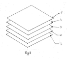
Fig. 1 : the resulted flexible material in the shape of a "sandwich", with five layers; -
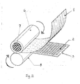
Fig. 2 : calander pressing machine; -
Fig. 3 : CNC non-standard Laser Cutting Machine; -
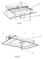
Fig. 4a : view from above of the cutting machine visualizing the aspirated air jet 11; -
Fig. 4b : view from bellow of the cutting machine visualizing the aspirated air jet 11; -
Fig. 5 : thevacuum machines 12 that evacuate the gas; -
Fig. 6 : the chassis of the cutting machine visualizing the aspirated directions of the gas; -
Fig. 7 : view from above of theguide rails 13 of the laser system; -
Fig. 8 : the A detail of therail 13; -
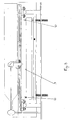
Fig. 9 : lateral side view of theguide rails 13 of the laser system; -
Fig. 10 : front side view of the cutting machine provided with thelens 14 for focusing the laser; -
Fig. 11 : detailed view of the cutting machine provided with the modifiedlaser tubes 15 and with themirrors 16; -
Fig. 12 : the resulted flexible material visualizing thesquares 17. - The process for realizing a flexible material from a rigid material, according o the invention, has the following steps:
- the
wood layer 3 is dyed in the wanted colour with a special dye by applying thelayer 4 above wood layer 3 (Fig.1 ). - the
layer 2 of special liquid glue is applied on the back side of thewood layer 3 using a silk-screen process. - a
flexible support layer 1 is applied above theglue layer 2. -
layer 1 is pressed together with theliquid glue layer 2 and thewood layer 3 by using a calander pressing machine (Fig.2 ), by rotating asteel cylinder 6 having someelements 7 preheated at 120°C; the rotation is reversed from the rubber cylinder 8. A perfect permanent and stable glued operation is realized betweenlayers - a
special hardener layer 5 is applyed on the front side of thewood layer 3 which gives the resulted flexible material two properties: strenghthening and waterproofing. - regular geometric shapes are cut in the
wood layer 3 leaving the fabric untouched by using a modified CNC cutting laser machine. - The resulted "sanwich" is almost ready to be used (
Fig.1 ) and it is formed of: -
flexible support layer 1, which may be of leather or flexible plastic - special
liquid glue 2 - wood
rigid layer 3 having the thickness of approximately 0,5 - 0,6 mm -
special wood dye 4 - special
formula wood hardener 5 - The transformation of this material in a flexible and soft one is realized with the help of the key machine that cuts regular geometric shapes in half thickness of the
wood layer 3. - This device is a modified CNC cutting laser machine provided with some equipments designed with CAD soft. This machine cuts regular geometric shapes in the
wood layer 3 of the above mentioned "sandwich", leaving the rest of the fabric untouched. The CNC cutting laser machine has been modified in order to get perfect cut patterns, overtaking the barriers of thewood layer 3 its self. - In order to cut a wood material efficiently, with precision and with a tolerance of 1/10 mm, the following three conditions must be fulfilled:
- the material to be cut must have a perfect plane surface
- the focusing distance between the laser output and the material has to be constant through all the surface to be cut
- the power of the laser beam must be constant during all working time
- In order to solve these problems, the CNC cutting laser machine (
Fig.3 ) presents the following modifications: - modified working table 9 provided with an adjustment screw 10 with micrometer precision on X and Y axis which insures a perfect plane working table and perfect parallelism between laser gantry axis and the table (
Fig.3 ); - custom made vacuum source that maintain the
wood layer 3 plane and glued on working table 9. The vacuum created by aspiration of the air jet 11 eliminates the risk of generating waves on the resulted flexible material's surface and allows the laser source to focus on the surface of the material (Fig.4a ,b); - custom made exhaust gas outlet on the cutting machine's chassis. Practically, several
gas vacuum cleaners 12 are used in order to keep the laser chamber clean. In this way, the exhausted gas do not affect and decrease the laser beam power and quality (Fig.5 ,Fig.6 ); - the two
guide rails 13 of the laser system are made of aluminium with hollow profile which is much lighter reaching a repositioning accuracy of 0, 05 mm (Fig.7a ,Fig.8, and Fig.9 ). Only with this precision it is possible to obtain perfect patterns. The standard gantry system of a commercial laser cutting machine has a standard tolerance in repositioning accuracy of 0, 1 mm because of the weight of the construction materials. This tolerance is too high and generates errors when multiplying the pattern. - the head of the laser is modified as follows: the average focusing distance to cut materials range from 63 mm to 100 mm and the depth of field (penetration of the laser beam into the material) vary from 3 mm to 20 mm. As said before, we just need to cut in half thickness the
wood layer 3 of the "sandwich". In order to reduce the depht of action field of the laser beam, the device is provided with some focusinglens 14 that reduce the focusing distance of the laser beam to 38,1 mm and the depht of the penetration to 1 mm (Fig.10 ); - the laser tube is also modified: the standard width of a laser cut in wood is about 0, 2 mm. This is too much wide. This device is provided with
non-standard laser tubes 15 with smaller beam output size and with twomirrors 16, producing a final cut width of 0, 1 mm (Fig.11 ). - In this way, a flexible material is obtained and it presents some
squares 17 on its surface (Fig.12 ). - The so resulted flexible material can be later manipulated, for example it can be cut in the wanted shapes or patterns even in heaps of 100 sheets tinted or natural looking, coloured or not.
- Because the resulted material can be cut in very big multi-layers, the flexible material can be used in the classic manufacturing industry as substitute or supplement for fabric or leather.
The process applies similarly to metals or rigid plastic materials.
Claims (2)
- Process for realizing a flexible material from a rigid material, where in, it follows the following steps: a special dye layer (4) is applied on the wood layer (3), then a layer (2) of special liquid glue is applied on the back side of the wood layer (3) using a silk-screen process similar to that used in the ceramic and glass processing, then a flexible support layer (1) is applied above the glue layer (2), after which the flexible support layer (1) is pressed together with the liquid glue layer (2) and the wood layer (3) by using a calander pressing machine, then a special hardener layer (5) is applyed on the front side of the wood layer (3) and, in the end, regular geometric shapes are cut in half depth of the wood layer (3) leaving the fabric untouched.
- Device for realizing a flexible material from a rigid material, similar with the CNC cutting laser devices, where in, the device is provided with a working table (9) provided with a adjusting screw (10) with micrometer precision on X and Y axis, a vacuum source that keeps the wood layer (3) plane and in touch with the working table (9), some gas vacuum cleaners (12), two guide rails (13) of the laser system made of aluminium with hollow profile system, some focusing lens (14), some modified laser tubes (15) and two mirrors (16) producing a final cut width of 0,1 mm.
Applications Claiming Priority (1)
| Application Number | Priority Date | Filing Date | Title |
|---|---|---|---|
| ROA201301034A RO129866A3 (en) | 2013-12-20 | 2013-12-20 | Process and equipment for making a flexible material from a rigid material |
Publications (1)
| Publication Number | Publication Date |
|---|---|
| EP2886240A1 true EP2886240A1 (en) | 2015-06-24 |
Family
ID=51210933
Family Applications (1)
| Application Number | Title | Priority Date | Filing Date |
|---|---|---|---|
| EP14001931.6A Withdrawn EP2886240A1 (en) | 2013-12-20 | 2014-06-04 | Process and device for realizing a flexible material from a rigid material |
Country Status (2)
| Country | Link |
|---|---|
| EP (1) | EP2886240A1 (en) |
| RO (1) | RO129866A3 (en) |
Cited By (3)
| Publication number | Priority date | Publication date | Assignee | Title |
|---|---|---|---|---|
| CN104625406A (en) * | 2014-12-15 | 2015-05-20 | 湖北三江航天红阳机电有限公司 | Adsorption clamping equipment for framework covering laser welding and method achieved through adsorption clamping equipment |
| PL425206A1 (en) * | 2018-04-12 | 2019-10-21 | Marzec Damian Hes | Method for vacuum fixing of machined workpieces to the working table |
| CN110744616A (en) * | 2018-07-23 | 2020-02-04 | 深圳市木村数控机床有限公司 | Numerical control machine tool special for processing screen diaphragm |
Citations (5)
| Publication number | Priority date | Publication date | Assignee | Title |
|---|---|---|---|---|
| GB728164A (en) * | 1952-11-10 | 1955-04-13 | Chadeloid Corp | Improvements in or relating to synthetic resin compositions suitable for use as porefillers |
| GB2294656A (en) * | 1994-11-07 | 1996-05-08 | Janet Stoyel | Method and apparatus for the manufacture of textiles |
| AU774314B2 (en) | 1999-08-17 | 2004-06-24 | Fiordland Souvenirs Limited | A flexible material and method of manufacturing of such from a substantially rigid material |
| WO2013069035A1 (en) * | 2011-11-09 | 2013-05-16 | My Mantra S.R.L. | Multilayer flexible element, preferably made of wood, and related production process by laser engraving and/or cutting |
| US20130216740A1 (en) | 2012-02-16 | 2013-08-22 | Apple Inc. | Interlocking flexible segments formed from a rigid material |
-
2013
- 2013-12-20 RO ROA201301034A patent/RO129866A3/en unknown
-
2014
- 2014-06-04 EP EP14001931.6A patent/EP2886240A1/en not_active Withdrawn
Patent Citations (5)
| Publication number | Priority date | Publication date | Assignee | Title |
|---|---|---|---|---|
| GB728164A (en) * | 1952-11-10 | 1955-04-13 | Chadeloid Corp | Improvements in or relating to synthetic resin compositions suitable for use as porefillers |
| GB2294656A (en) * | 1994-11-07 | 1996-05-08 | Janet Stoyel | Method and apparatus for the manufacture of textiles |
| AU774314B2 (en) | 1999-08-17 | 2004-06-24 | Fiordland Souvenirs Limited | A flexible material and method of manufacturing of such from a substantially rigid material |
| WO2013069035A1 (en) * | 2011-11-09 | 2013-05-16 | My Mantra S.R.L. | Multilayer flexible element, preferably made of wood, and related production process by laser engraving and/or cutting |
| US20130216740A1 (en) | 2012-02-16 | 2013-08-22 | Apple Inc. | Interlocking flexible segments formed from a rigid material |
Cited By (4)
| Publication number | Priority date | Publication date | Assignee | Title |
|---|---|---|---|---|
| CN104625406A (en) * | 2014-12-15 | 2015-05-20 | 湖北三江航天红阳机电有限公司 | Adsorption clamping equipment for framework covering laser welding and method achieved through adsorption clamping equipment |
| PL425206A1 (en) * | 2018-04-12 | 2019-10-21 | Marzec Damian Hes | Method for vacuum fixing of machined workpieces to the working table |
| CN110744616A (en) * | 2018-07-23 | 2020-02-04 | 深圳市木村数控机床有限公司 | Numerical control machine tool special for processing screen diaphragm |
| CN110744616B (en) * | 2018-07-23 | 2021-07-16 | 深圳市木村数控机床有限公司 | Numerical control machine tool special for processing screen diaphragm |
Also Published As
| Publication number | Publication date |
|---|---|
| RO129866A3 (en) | 2015-06-30 |
| RO129866A0 (en) | 2014-11-28 |
Similar Documents
| Publication | Publication Date | Title |
|---|---|---|
| CN105817766B (en) | Laser Ablation Method with Slice Optimization | |
| EP2886240A1 (en) | Process and device for realizing a flexible material from a rigid material | |
| JP2016530397A5 (en) | ||
| CN104249219B (en) | A kind of method of big width laser engraving | |
| WO2012005454A3 (en) | Glass substrate cutting system using laser | |
| Qi et al. | Laser cutting of irregular shape object based on stereo vision laser galvanometric scanning system | |
| CN106077972A (en) | A kind of real-time carving depth that actively controls realizes the method and apparatus of laser three-D stereo carving | |
| CN106457462A (en) | Method for manufacturing decorative part | |
| CN205529623U (en) | Automatic cloth cutter that cuts of gluing machine | |
| CN205058616U (en) | Single three -dimensional solidification system of printing in laser instrument duplex position | |
| JP2017196655A (en) | Processing method using laser blanking device | |
| KR20170042892A (en) | A supporting structure for a workpiece | |
| KR101252288B1 (en) | fancy wood product manufacturing system using laser-beam. | |
| CN204524544U (en) | A kind of vision positioning system of small breadth high-speed precision cutting machine | |
| CN101985184A (en) | Method for cutting materials by using numerical control flame-cutting machine | |
| CN203109966U (en) | Adhesive film cutter for chemical milling of small opening U-type aluminum alloy piece | |
| CN205393246U (en) | Pneumatic bending machine | |
| CN202668683U (en) | Numerical control curve feeding platform for find woodworking band-sawing machine | |
| CN207479751U (en) | A kind of bloom rose reamer for the double angle blades of hilted broadsword | |
| KR102688608B1 (en) | Cutting blade supply for wood molds | |
| KR20180079032A (en) | Process of laser surface treatment of ceramics used in precious metals | |
| KR20110067563A (en) | Surface Glyph Implementation Using 3D Scanner and 3 Axis Laser Marking Head | |
| KR20140000550U (en) | Bending jig | |
| CN203664829U (en) | Aluminum alloy profile cutting device | |
| CN204074974U (en) | Sheet metal component bending locator group |
Legal Events
| Date | Code | Title | Description |
|---|---|---|---|
| PUAI | Public reference made under article 153(3) epc to a published international application that has entered the european phase |
Free format text: ORIGINAL CODE: 0009012 |
|
| 17P | Request for examination filed |
Effective date: 20140604 |
|
| AK | Designated contracting states |
Kind code of ref document: A1 Designated state(s): AL AT BE BG CH CY CZ DE DK EE ES FI FR GB GR HR HU IE IS IT LI LT LU LV MC MK MT NL NO PL PT RO RS SE SI SK SM TR |
|
| AX | Request for extension of the european patent |
Extension state: BA ME |
|
| STAA | Information on the status of an ep patent application or granted ep patent |
Free format text: STATUS: THE APPLICATION IS DEEMED TO BE WITHDRAWN |
|
| 18D | Application deemed to be withdrawn |
Effective date: 20160105 |