EP2886044A1 - System and a method for acquisition of biopotential signals with motion artifact reduction. - Google Patents
System and a method for acquisition of biopotential signals with motion artifact reduction. Download PDFInfo
- Publication number
- EP2886044A1 EP2886044A1 EP14156018.5A EP14156018A EP2886044A1 EP 2886044 A1 EP2886044 A1 EP 2886044A1 EP 14156018 A EP14156018 A EP 14156018A EP 2886044 A1 EP2886044 A1 EP 2886044A1
- Authority
- EP
- European Patent Office
- Prior art keywords
- signal
- reference signal
- biopotential
- ref1
- analogue
- Prior art date
- Legal status (The legal status is an assumption and is not a legal conclusion. Google has not performed a legal analysis and makes no representation as to the accuracy of the status listed.)
- Granted
Links
Images


Classifications
-
- A—HUMAN NECESSITIES
- A61—MEDICAL OR VETERINARY SCIENCE; HYGIENE
- A61B—DIAGNOSIS; SURGERY; IDENTIFICATION
- A61B5/00—Measuring for diagnostic purposes; Identification of persons
- A61B5/72—Signal processing specially adapted for physiological signals or for diagnostic purposes
- A61B5/7203—Signal processing specially adapted for physiological signals or for diagnostic purposes for noise prevention, reduction or removal
- A61B5/7207—Signal processing specially adapted for physiological signals or for diagnostic purposes for noise prevention, reduction or removal of noise induced by motion artifacts
-
- A—HUMAN NECESSITIES
- A61—MEDICAL OR VETERINARY SCIENCE; HYGIENE
- A61B—DIAGNOSIS; SURGERY; IDENTIFICATION
- A61B5/00—Measuring for diagnostic purposes; Identification of persons
- A61B5/24—Detecting, measuring or recording bioelectric or biomagnetic signals of the body or parts thereof
- A61B5/30—Input circuits therefor
- A61B5/307—Input circuits therefor specially adapted for particular uses
- A61B5/308—Input circuits therefor specially adapted for particular uses for electrocardiography [ECG]
-
- A—HUMAN NECESSITIES
- A61—MEDICAL OR VETERINARY SCIENCE; HYGIENE
- A61B—DIAGNOSIS; SURGERY; IDENTIFICATION
- A61B5/00—Measuring for diagnostic purposes; Identification of persons
- A61B5/24—Detecting, measuring or recording bioelectric or biomagnetic signals of the body or parts thereof
- A61B5/316—Modalities, i.e. specific diagnostic methods
- A61B5/318—Heart-related electrical modalities, e.g. electrocardiography [ECG]
- A61B5/346—Analysis of electrocardiograms
-
- A—HUMAN NECESSITIES
- A61—MEDICAL OR VETERINARY SCIENCE; HYGIENE
- A61B—DIAGNOSIS; SURGERY; IDENTIFICATION
- A61B5/00—Measuring for diagnostic purposes; Identification of persons
- A61B5/72—Signal processing specially adapted for physiological signals or for diagnostic purposes
- A61B5/7203—Signal processing specially adapted for physiological signals or for diagnostic purposes for noise prevention, reduction or removal
- A61B5/7207—Signal processing specially adapted for physiological signals or for diagnostic purposes for noise prevention, reduction or removal of noise induced by motion artifacts
- A61B5/7214—Signal processing specially adapted for physiological signals or for diagnostic purposes for noise prevention, reduction or removal of noise induced by motion artifacts using signal cancellation, e.g. based on input of two identical physiological sensors spaced apart, or based on two signals derived from the same sensor, for different optical wavelengths
-
- A—HUMAN NECESSITIES
- A61—MEDICAL OR VETERINARY SCIENCE; HYGIENE
- A61B—DIAGNOSIS; SURGERY; IDENTIFICATION
- A61B5/00—Measuring for diagnostic purposes; Identification of persons
- A61B5/72—Signal processing specially adapted for physiological signals or for diagnostic purposes
- A61B5/7235—Details of waveform analysis
- A61B5/7246—Details of waveform analysis using correlation, e.g. template matching or determination of similarity
Definitions
- the present invention relates generally to the field of biopotential signal acquisition systems and more specifically to a system and a method for acquisition of biopotential signals with motion artifact reduction using digital adaptive filtering.
- ECG electrocardiogram
- EEG electroencephalogram
- EMG electromyogram
- An approach to reduce motion artifacts is by using digital adaptive filtering.
- digital adaptive filtering e.g. a LMS filter
- EP 2 591 720 A1 uses digital adaptive filtering (e.g. a LMS filter), implemented in a digital domain, to calculate a motion artifact estimate which is then fed back to the analogue domain and subtracted from the measured ECG before final amplification.
- a new biopotential signal acquisition system is provided with improved motion artifact reduction.
- the invention is advantageous for ambulatory and/or low power biopotential monitoring applications.
- a biopotential signal acquisition system comprising: an analogue readout unit configured to receive an analogue biopotential signal and to extract, from that received analogue biopotential signal, an analogue measured biopotential signal and an analogue reference signal; an ADC unit configured to provide a digital version of the analogue measured biopotential signal and the analogue reference signal; a digital filter unit configured to calculate a digital motion artifact estimate based on the digital version of the measured biopotential signal and the reference signal; and wherein the system further comprises a reference signal processing unit configured to convert the reference signal into a new reference signal being provided to the digital filter unit based on the correlation between the measured biopotential signal and the reference signal.
- the received analogue biopotential signal may be acquired, for example, from at least one electrode attached to a living being's body.
- the correlation between the measured biopotential signal and the reference signal may be estimated by calculating the correlation between the motion artifact estimate signal and the reference signal.
- the correlation between the measured biopotential signal and the reference signal may be estimated by calculating the correlation between the analogue biopotential signal and the reference signal.
- the polarity of the new reference signal may be calculated based on the correlation between the measured biopotential signal and the reference signal.
- the polarity of the new reference signal may be the same or opposite to the polarity of the reference signal depending on the correlation between the measured biopotential signal and the reference signal.
- the reference signal processing unit may be implemented in an analogue domain part or digital domain part of the system.
- the digital filter unit may implement or runs a digital adaptive filter, such as, for example an LMS filter.
- the reference signal may be an electrode-tissue impedance signal.
- the analogue biopotential signal may be an ECG signal.
- a method for acquisition of biopotential signals comprising: extracting, from an analogue biopotential signal, an analogue measured biopotential signal and an analogue reference signal; converting the reference signal into a new reference signal based on the correlation between the measured biopotential signal and the reference signal; and calculating a digital motion artifact estimate based on the digital version of the measured biopotential signal and the new reference signal.
- FIG. 1 shows a first exemplary block diagram of a biopotential signal acquisition system 100 according to an embodiment of the invention.
- the system comprises an analogue domain part 50 configured to receive at least one analogue biopotential signal BS1, which may be acquired, for example, from at least one sensor electrode attached to a living being body, and comprises an analogue readout unit 10 which extracts at least one analogue measured biopotential signal BS2 and at least one analogue reference signal REF1.
- the analogue measured biopotential signal BS2 and the analogue reference signal REF1 are then provided to an analogue-to-digital converter (ADC) unit 20, which comprises one or more ADCs configured to convert those signals into digital versions which are then handled in the digital domain part 60 of the system.
- ADC analogue-to-digital converter
- a reference signal processing unit 30 receives the digital versions of the measured biopotential signal BS2 and the reference signal REF1 and is configured to calculate a correlation between both signals and generate a new reference signal REF2 based on the value of that correlation. Then, a digital filter unit 40 receives the measured biopotential signal BS2 and the new reference signal REF2 and calculates an estimated noise or motion artifact estimate MA, which is used to reduce the motion artifact from the measured biopotential signal.
- the reference signal processing unit 30 based on the correlation value between the measured biopotential signal BS2 and the reference signal REF1, checks the polarity between both signals and adapts the reference signal REF1 based on such polarity value. If the polarity information has a first value, indicating that the reference signal REF1 has the same polarity as the measured biopotential signal BS2, then the reference signal processing unit 30 provides a signal REF2 that is the same as reference signal REF1 to the digital filter unit 40; if the polarity information has a second value, indicating that the reference signal REF1 has an opposite polarity than the measured biopotential signal BS2, then the reference signal processing unit 30 provides a signal REF2 that has polarity opposite to the polarity of the reference signal REF1.
- the correlation value between the measured biopotential signal BS2 and the reference signal REF1 is calculated continuously.
- the correlation value varies between a maximum value, e.g. +1, in the case of a perfect positive (increasing) linear relationship (correlation) and a minimum value, e.g. -1, in case of a perfect decreasing (negative) linear relationship (anti-correlation), depending on the degree of linear dependence between the signals.
- the polarity calculation is then performed by comparing the calculated correlation value with a certain threshold value, which can be a certain predefined value or dynamically calculated.
- the polarity value in case the calculated correlation value is equal to and/or greater than a certain threshold value, the polarity value is given a first value, e.g. 0, and in case the calculated correlation value is equal to and/or lower than a certain threshold value, the polarity value is given a second value, e.g. 1.
- the polarity value once the polarity value is updated, it is maintained for a certain period of time in order to avoid oscillation.
- the reference signal processing unit 30 generates a new reference signal REF2, which is an adaptation of the received reference signal REF1.
- the new reference input REF2 for the digital filter unit 40 is generated.
- the new reference signal REF2 is the same as the received reference signal REF1 in case the received reference signal REF1 has the same polarity as the measured biopotential signal BS2, and the new reference signal REF2 is a signal that has polarity opposite to the polarity of the reference signal REF1 in case the received reference signal REF1 has an opposite polarity than the measured biopotential signal BS2.
- the correlation value between the measured biopotential signal BS2 and the reference signal REF1 may be also estimated by calculating the correlation between the estimated noise signal or motion artifact estimate MA at the output of the digital filter unit 40 and the reference signal REF1.
- the correlation value between the measured biopotential signal BS2 and the reference signal REF1 may be estimated by calculating the correlation between the analogue biopotential signal BS1 and the reference signal REF1.
- the new reference signal REF2 has higher correlation with the measured biopotential signal BS2, which improves the performance of the digital filter unit 40 for calculation of the motion artifact estimate MA.
- the motion artifact estimate MA can be calculated faster and with more accuracy, which in turn improves motion artifact reduction.
- the biopotential signal acquisition system 100 works in real-time.
- the analogue biopotential signal BS1 is an electrocardiogram signal and the reference signal REF1 is an electrode-tissue impedance signal.
- Other reference signals could be used, such as for example, a galvanic skin response (GSR), a photoplethysmogram (PPG) or a bio impedance signal.
- GSR galvanic skin response
- PPG photoplethysmogram
- the digital filter unit 40 may implement or run a digital adaptive filter, for example, a Least Mean Square (LMS) filter.
- LMS Least Mean Square
- the reference signal processing unit 30 may be implemented as part of the digital filter unit 40, for example, as part of the LMS filter.
- the digital filter unit 40 and the reference signal processing unit 30 may be implemented in hardware and/or software, in a dedicated digital domain part 60 and in the same chip as the analogue part 50.
- the digital filter unit 40 and the reference signal processing unit 30 may be implemented in hardware and/or software in an off-chip or external microcontroller or microprocessor.
- all the modules sown in Figure 1 may be integrated on a single chip. This is advantageous for example to reduce the group delay for real time solution and/or to reduce the power consumption.
- FIG. 2 shows a second exemplary block diagram of a biopotential signal acquisition system 100 according to an embodiment of the invention. Basically the same working principle as the one explained Figure 1 applies, but for the fact that now the reference signal processing unit 30 is implemented in the analogue domain part 50 and adapts the reference signal REF1 in such domain.
- FIG. 3 shows a simplified flow diagram of a method for acquisition of biopotential signals with motion artifact reduction according to an embodiment of the invention.
- the method comprises, in a first step S1, calculating the correlation between a measured biopotential signal BS2 and a reference signal REF1; in a second step S2, calculating the polarity between the measured biopotential signal BS2 and a reference signal REF1; and, in a third step S3, generating a new reference signal REF2 which is provided to a digital filter unit for motion artifact estimation.
- the correlation value between a measured biopotential signal BS2 and a reference signal REF1 is calculated in a first step S1. This may be done, in exemplary implementations, continuously and with a certain sampling rate in order to reduce the active power consumption.
- Dataln_A is the motion artifact estimate signal MA
- Dataln_B is the reference signal REF 1
- corr is the correlation value.
- the sampling rate (32) may be changed and is a design option.
- the correlation value may be +1 in case of a perfect positive (increasing) linear relationship (correlation), and -1 in case of a perfect decreasing (negative) linear relationship (anti-correlation), and some value between -1 and 1 in all other cases, indicating the degree of linear dependence between the variables. As it approaches zero there is less of a relationship (closer to uncorrelated).
- corr is the correlation value and CORR_TH is a certain threshold value.
- CORR_TH is a certain threshold value.
- the polarity may stay for a certain period of time, for example at least for 1 second. This period of time can be programmed and is a design option.
- refpos is the reference input
- refneg is the reference signal with opposite polarity
- REF_OFF is a reference offset, which may be designed according to the acquisition environment such as subject, type of electrode, quality of electrode, etc., and its value may be adjusted at the beginning, and updated regularly during the operation.
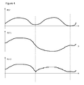
- Figure 4 illustrates exemplary graphs of the measured biopotential signal BS2, the reference signal REF1 and the new reference signal REF2 generated in a biopotential signal acquisition system according to an embodiment of the invention.
- the new reference signal REF2 is an adaptation of the reference signal REF1, in which the polarity of the reference signal REF1 changed such that it has a higher correlation with the measured biopotential signal BS2.
Landscapes
- Health & Medical Sciences (AREA)
- Life Sciences & Earth Sciences (AREA)
- Engineering & Computer Science (AREA)
- Surgery (AREA)
- Animal Behavior & Ethology (AREA)
- Veterinary Medicine (AREA)
- Public Health (AREA)
- Physics & Mathematics (AREA)
- General Health & Medical Sciences (AREA)
- Biophysics (AREA)
- Pathology (AREA)
- Biomedical Technology (AREA)
- Heart & Thoracic Surgery (AREA)
- Medical Informatics (AREA)
- Molecular Biology (AREA)
- Signal Processing (AREA)
- Artificial Intelligence (AREA)
- Physiology (AREA)
- Computer Vision & Pattern Recognition (AREA)
- Psychiatry (AREA)
- Cardiology (AREA)
- Measurement And Recording Of Electrical Phenomena And Electrical Characteristics Of The Living Body (AREA)
Abstract
Description
- The present invention relates generally to the field of biopotential signal acquisition systems and more specifically to a system and a method for acquisition of biopotential signals with motion artifact reduction using digital adaptive filtering.
- Ambulatory monitoring of biopotential signals, such as electrocardiogram (ECG), electroencephalogram (EEG), electromyogram (EMG), etc., is a highly relevant topic in personal healthcare. A key technical challenge in such application environments is overcoming motion artifacts that significantly affect the recorded biopotential signals. An approach to reduce motion artifacts is by using digital adaptive filtering. For example, a known biomedical acquisition system with motion artifact reduction is disclosed in
EP 2 591 720 A1 , which uses digital adaptive filtering (e.g. a LMS filter), implemented in a digital domain, to calculate a motion artifact estimate which is then fed back to the analogue domain and subtracted from the measured ECG before final amplification. Another known technique for motion artifact removal using a two-stage cascade LMS adptive filter is disclosed in the document " Motion Artifact Removal using Cascade Adaptive Filtering for Ambulatory ECG Monitoring System", by Hyejung Kim et al., Biomedical Circuits and Systems Conference (BioCAS), November 2012 IEEE, Hsinchu, Taiwan. - According to one aspect of the present invention, a new biopotential signal acquisition system is provided with improved motion artifact reduction. According to another aspects the invention is advantageous for ambulatory and/or low power biopotential monitoring applications.
- According to an exemplary embodiment, there is provided a biopotential signal acquisition system comprising: an analogue readout unit configured to receive an analogue biopotential signal and to extract, from that received analogue biopotential signal, an analogue measured biopotential signal and an analogue reference signal; an ADC unit configured to provide a digital version of the analogue measured biopotential signal and the analogue reference signal; a digital filter unit configured to calculate a digital motion artifact estimate based on the digital version of the measured biopotential signal and the reference signal; and wherein the system further comprises a reference signal processing unit configured to convert the reference signal into a new reference signal being provided to the digital filter unit based on the correlation between the measured biopotential signal and the reference signal. The received analogue biopotential signal may be acquired, for example, from at least one electrode attached to a living being's body.
- According to an exemplary embodiment, the correlation between the measured biopotential signal and the reference signal may be estimated by calculating the correlation between the motion artifact estimate signal and the reference signal.
- According to an exemplary embodiment, the correlation between the measured biopotential signal and the reference signal may be estimated by calculating the correlation between the analogue biopotential signal and the reference signal.
- According to an exemplary embodiment, the polarity of the new reference signal may be calculated based on the correlation between the measured biopotential signal and the reference signal. The polarity of the new reference signal may be the same or opposite to the polarity of the reference signal depending on the correlation between the measured biopotential signal and the reference signal.
- According to an exemplary embodiment, the reference signal processing unit may be implemented in an analogue domain part or digital domain part of the system.
- According to an exemplary embodiment, the digital filter unit may implement or runs a digital adaptive filter, such as, for example an LMS filter.
- According to an exemplary embodiment, the reference signal may be an electrode-tissue impedance signal. According to an exemplary embodiment, the analogue biopotential signal may be an ECG signal.
- There is also provided and electronic device comprising a biopotential signal acquisition system according to any of the embodiments herein described.
- There is also provided a method for acquisition of biopotential signals, comprising: extracting, from an analogue biopotential signal, an analogue measured biopotential signal and an analogue reference signal; converting the reference signal into a new reference signal based on the correlation between the measured biopotential signal and the reference signal; and calculating a digital motion artifact estimate based on the digital version of the measured biopotential signal and the new reference signal.
- Certain objects and advantages of various new and inventive aspects have been described above. It is to be understood that not necessarily all such objects or advantages may be achieved in accordance with any particular embodiment of the present invention. Those skilled in the art will recognize that the solution of the present invention may be embodied or carried out in a manner that achieves or optimizes one advantage or group of advantages without necessarily achieving other objects or advantages.
- The above and other aspects of the system and method for acquisition of biopotential signals according to the present invention will be shown and explained with reference to the non-restrictive example embodiments described hereinafter.
-
Figure 1 shows a first exemplary block diagram of a biopotential signal acquisition system according to an embodiment of the invention. -
Figure 2 shows a second exemplary block diagram of a biopotential signal acquisition system according to an embodiment of the invention. -
Figure 3 shows a flow diagram of a method for acquisition of biopotential signals according to an embodiment of the invention. -
Figure 4 illustrates exemplary graphs of signals generated in a biopotential signal acquisition system according to an embodiment of the invention. - In the following, in the description of exemplary embodiments, various features may be grouped together in a single embodiment, figure, or description thereof for the purpose of streamlining the disclosure and aiding in the understanding of one or more of the various inventive aspects. This is however not to be interpreted as the invention requiring more features than the ones expressly recited in the main claim. Furthermore, combinations of features of different embodiments are meant to be within the scope of the invention, as would be clearly understood by those skilled in the art. Additionally, in other instances, well-known methods, structures and techniques have not been shown in detail in order not to obscure the conciseness of the description.
-
Figure 1 shows a first exemplary block diagram of a biopotentialsignal acquisition system 100 according to an embodiment of the invention. The system comprises ananalogue domain part 50 configured to receive at least one analogue biopotential signal BS1, which may be acquired, for example, from at least one sensor electrode attached to a living being body, and comprises ananalogue readout unit 10 which extracts at least one analogue measured biopotential signal BS2 and at least one analogue reference signal REF1. The analogue measured biopotential signal BS2 and the analogue reference signal REF1 are then provided to an analogue-to-digital converter (ADC)unit 20, which comprises one or more ADCs configured to convert those signals into digital versions which are then handled in thedigital domain part 60 of the system. A referencesignal processing unit 30 receives the digital versions of the measured biopotential signal BS2 and the reference signal REF1 and is configured to calculate a correlation between both signals and generate a new reference signal REF2 based on the value of that correlation. Then, adigital filter unit 40 receives the measured biopotential signal BS2 and the new reference signal REF2 and calculates an estimated noise or motion artifact estimate MA, which is used to reduce the motion artifact from the measured biopotential signal. - According to an exemplary embodiment, the reference
signal processing unit 30, based on the correlation value between the measured biopotential signal BS2 and the reference signal REF1, checks the polarity between both signals and adapts the reference signal REF1 based on such polarity value. If the polarity information has a first value, indicating that the reference signal REF1 has the same polarity as the measured biopotential signal BS2, then the referencesignal processing unit 30 provides a signal REF2 that is the same as reference signal REF1 to thedigital filter unit 40; if the polarity information has a second value, indicating that the reference signal REF1 has an opposite polarity than the measured biopotential signal BS2, then the referencesignal processing unit 30 provides a signal REF2 that has polarity opposite to the polarity of the reference signal REF1. - According to an exemplary embodiment, the correlation value between the measured biopotential signal BS2 and the reference signal REF1 is calculated continuously. According to an exemplary embodiment, the correlation value varies between a maximum value, e.g. +1, in the case of a perfect positive (increasing) linear relationship (correlation) and a minimum value, e.g. -1, in case of a perfect decreasing (negative) linear relationship (anti-correlation), depending on the degree of linear dependence between the signals. The polarity calculation is then performed by comparing the calculated correlation value with a certain threshold value, which can be a certain predefined value or dynamically calculated. According to an exemplary embodiment, in case the calculated correlation value is equal to and/or greater than a certain threshold value, the polarity value is given a first value, e.g. 0, and in case the calculated correlation value is equal to and/or lower than a certain threshold value, the polarity value is given a second value, e.g. 1. According to an exemplary embodiment, once the polarity value is updated, it is maintained for a certain period of time in order to avoid oscillation.
- According to an exemplary embodiment, the reference
signal processing unit 30 generates a new reference signal REF2, which is an adaptation of the received reference signal REF1. By using the polarity information, the new reference input REF2 for thedigital filter unit 40 is generated. The new reference signal REF2 is the same as the received reference signal REF1 in case the received reference signal REF1 has the same polarity as the measured biopotential signal BS2, and the new reference signal REF2 is a signal that has polarity opposite to the polarity of the reference signal REF1 in case the received reference signal REF1 has an opposite polarity than the measured biopotential signal BS2. - According to an exemplary embodiment, the correlation value between the measured biopotential signal BS2 and the reference signal REF1 may be also estimated by calculating the correlation between the estimated noise signal or motion artifact estimate MA at the output of the
digital filter unit 40 and the reference signal REF1. According to another exemplary embodiment, the correlation value between the measured biopotential signal BS2 and the reference signal REF1 may be estimated by calculating the correlation between the analogue biopotential signal BS1 and the reference signal REF1. - Advantageously, according to an exemplary embodiment of the invention, the new reference signal REF2 has higher correlation with the measured biopotential signal BS2, which improves the performance of the
digital filter unit 40 for calculation of the motion artifact estimate MA. In consequence, the motion artifact estimate MA can be calculated faster and with more accuracy, which in turn improves motion artifact reduction. - According to an exemplary embodiment, the biopotential
signal acquisition system 100 works in real-time. - According to an exemplary embodiment, the analogue biopotential signal BS1 is an electrocardiogram signal and the reference signal REF1 is an electrode-tissue impedance signal. Other reference signals could be used, such as for example, a galvanic skin response (GSR), a photoplethysmogram (PPG) or a bio impedance signal.
- According to an exemplary embodiment, the
digital filter unit 40 may implement or run a digital adaptive filter, for example, a Least Mean Square (LMS) filter. According to an exemplary embodiment, the referencesignal processing unit 30 may be implemented as part of thedigital filter unit 40, for example, as part of the LMS filter. Thedigital filter unit 40 and the referencesignal processing unit 30 may be implemented in hardware and/or software, in a dedicateddigital domain part 60 and in the same chip as theanalogue part 50. According to an exemplary embodiment, thedigital filter unit 40 and the referencesignal processing unit 30 may be implemented in hardware and/or software in an off-chip or external microcontroller or microprocessor. - According to one exemplary embodiment, all the modules sown in
Figure 1 may be integrated on a single chip. This is advantageous for example to reduce the group delay for real time solution and/or to reduce the power consumption. -
Figure 2 shows a second exemplary block diagram of a biopotentialsignal acquisition system 100 according to an embodiment of the invention. Basically the same working principle as the one explainedFigure 1 applies, but for the fact that now the referencesignal processing unit 30 is implemented in theanalogue domain part 50 and adapts the reference signal REF1 in such domain. -
Figure 3 shows a simplified flow diagram of a method for acquisition of biopotential signals with motion artifact reduction according to an embodiment of the invention. The method comprises, in a first step S1, calculating the correlation between a measured biopotential signal BS2 and a reference signal REF1; in a second step S2, calculating the polarity between the measured biopotential signal BS2 and a reference signal REF1; and, in a third step S3, generating a new reference signal REF2 which is provided to a digital filter unit for motion artifact estimation. - According to an exemplary embodiment, the correlation value between a measured biopotential signal BS2 and a reference signal REF1 is calculated in a first step S1. This may be done, in exemplary implementations, continuously and with a certain sampling rate in order to reduce the active power consumption. According to exemplary implementations, the estimated motion artifact signal MA may be also used for calculating the correlation value according to the equation:

- wherein Dataln_A is the motion artifact estimate signal MA, Dataln_B is the reference signal REF 1 and corr is the correlation value. The sampling rate (32) may be changed and is a design option.
- According to an exemplary embodiment, the correlation value may be +1 in case of a perfect positive (increasing) linear relationship (correlation), and -1 in case of a perfect decreasing (negative) linear relationship (anti-correlation), and some value between -1 and 1 in all other cases, indicating the degree of linear dependence between the variables. As it approaches zero there is less of a relationship (closer to uncorrelated).
- According to an exemplary embodiment, after calculating the correlation value, a polarity calculation may be performed, for example as a polarity change request signal, req_p, which is generated as the following equation:

- Where corr is the correlation value and CORR_TH is a certain threshold value. To avoid the oscillation, once the polarity is updated, it may stay for a certain period of time, for example at least for 1 second. This period of time can be programmed and is a design option.
- According to an exemplary embodiment, by using polarity information, the new reference input REF2 for the digital filter is updated as in the following equation:

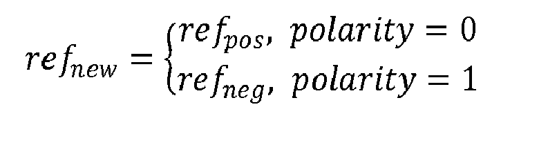
- where refpos is the reference input, and refneg is the reference signal with opposite polarity. REF_OFF is a reference offset, which may be designed according to the acquisition environment such as subject, type of electrode, quality of electrode, etc., and its value may be adjusted at the beginning, and updated regularly during the operation.
-
Figure 4 illustrates exemplary graphs of the measured biopotential signal BS2, the reference signal REF1 and the new reference signal REF2 generated in a biopotential signal acquisition system according to an embodiment of the invention. As illustrated in the figure, the new reference signal REF2 is an adaptation of the reference signal REF1, in which the polarity of the reference signal REF1 changed such that it has a higher correlation with the measured biopotential signal BS2.
Claims (11)
- A biopotential signal acquisition system (100) comprising:an analogue readout unit (10) configured to receive an analogue biopotential signal (BS1) and to extract, from that received analogue biopotential signal, an analogue measured biopotential signal (BS2) and an analogue reference signal (REF1);an ADC unit (20) configured to provide a digital version of the analogue measured biopotential signal (BS2) and the analogue reference signal (REF1);a digital filter unit (40) configured to calculate a digital motion artifact estimate (MA) based on the digital version of the measured biopotential signal (BS2) and the reference signal (REF1);characterized in thatthe system further comprises a reference signal processing unit (30) configured to convert the reference signal (REF1) into a new reference signal (REF2) being provided to the digital filter unit (40) based on the correlation between the measured biopotential signal (BS2) and the reference signal (REF1).
- A biopotential signal acquisition system according to claim 1, wherein the correlation between the measured biopotential signal (BS2) and the reference signal (REF1) is estimated by calculating the correlation between the motion artifact estimate signal (MA) and the reference signal (REF1).
- A biopotential signal acquisition system according to claim 1 or 2, wherein the polarity of the new reference signal (REF2) is calculated based on the correlation between the measured biopotential signal (BS2) and the reference signal (REF1).
- A biopotential signal acquisition system according to claim 3, wherein the polarity of the new reference signal (REF2) is the same or opposite to the polarity of the reference signal (REF1) depending on the correlation between the measured biopotential signal (BS2) and the reference signal (REF1).
- A biopotential signal acquisition system according to any of the previous claims, wherein the reference signal processing unit (30) is implemented in an analogue domain part (50) or a digital domain part (60) of the system (100).
- A biopotential signal acquisition system according to any of the previous claims, wherein the digital filter unit (40) implements or runs a digital adaptive filter.
- A biopotential signal acquisition system according to claim 6, wherein the digital adaptive filter is an LMS filter.
- A biopotential signal acquisition system according to any of the previous claims, wherein the reference signal (REF1) is an electrode-tissue impedance signal.
- A biopotential signal acquisition system according to any of the previous claims, wherein the analogue biopotential signal (BS1) is an ECG signal.
- Electronic device comprising a biopotential signal acquisition system (100) according to any of claims 1 to 9.
- A method for acquisition of biopotential signals, comprising:extracting, from an analogue biopotential signal (BS1), an analogue measured biopotential signal (BS2) and an analogue reference signal (REF1);converting the reference signal (REF1) into a new reference signal (REF2) based on the correlation between the measured biopotential signal (BS2) and the reference signal (REF1); andcalculating a digital motion artifact estimate (MA) based on the digital version of the measured biopotential signal (BS2) and the new reference signal (REF2).
Priority Applications (2)
| Application Number | Priority Date | Filing Date | Title |
|---|---|---|---|
| EP14156018.5A EP2886044B1 (en) | 2013-12-23 | 2014-02-20 | System and a method for acquisition of ECG signals with motion artifact reduction. |
| US14/573,714 US9375182B2 (en) | 2013-12-23 | 2014-12-17 | System and method for acquisition of biopotential signals with motion artifact reduction |
Applications Claiming Priority (2)
| Application Number | Priority Date | Filing Date | Title |
|---|---|---|---|
| EP13199276 | 2013-12-23 | ||
| EP14156018.5A EP2886044B1 (en) | 2013-12-23 | 2014-02-20 | System and a method for acquisition of ECG signals with motion artifact reduction. |
Publications (2)
| Publication Number | Publication Date |
|---|---|
| EP2886044A1 true EP2886044A1 (en) | 2015-06-24 |
| EP2886044B1 EP2886044B1 (en) | 2019-08-28 |
Family
ID=49920053
Family Applications (1)
| Application Number | Title | Priority Date | Filing Date |
|---|---|---|---|
| EP14156018.5A Active EP2886044B1 (en) | 2013-12-23 | 2014-02-20 | System and a method for acquisition of ECG signals with motion artifact reduction. |
Country Status (2)
| Country | Link |
|---|---|
| US (1) | US9375182B2 (en) |
| EP (1) | EP2886044B1 (en) |
Cited By (1)
| Publication number | Priority date | Publication date | Assignee | Title |
|---|---|---|---|---|
| CN110337266A (en) * | 2017-02-21 | 2019-10-15 | 皇家飞利浦有限公司 | Device and method for the measuring electrode impedance during electrophysiologicalmeasurements measurements |
Families Citing this family (1)
| Publication number | Priority date | Publication date | Assignee | Title |
|---|---|---|---|---|
| US11617531B2 (en) * | 2018-11-23 | 2023-04-04 | Mediatek Inc. | Circuit applied to biopotential acquisition system |
Citations (2)
| Publication number | Priority date | Publication date | Assignee | Title |
|---|---|---|---|---|
| US20080033266A1 (en) * | 1994-10-07 | 2008-02-07 | Diab Mohamed K | Signal processing apparatus |
| EP2561805A1 (en) * | 2011-08-25 | 2013-02-27 | Samsung Electronics Co., Ltd. | Apparatus and method for measuring bioelectric signals |
Family Cites Families (1)
| Publication number | Priority date | Publication date | Assignee | Title |
|---|---|---|---|---|
| US8914099B2 (en) | 2011-11-08 | 2014-12-16 | Imec | Biomedical acquisition system with motion artifact reduction |
-
2014
- 2014-02-20 EP EP14156018.5A patent/EP2886044B1/en active Active
- 2014-12-17 US US14/573,714 patent/US9375182B2/en not_active Expired - Fee Related
Patent Citations (2)
| Publication number | Priority date | Publication date | Assignee | Title |
|---|---|---|---|---|
| US20080033266A1 (en) * | 1994-10-07 | 2008-02-07 | Diab Mohamed K | Signal processing apparatus |
| EP2561805A1 (en) * | 2011-08-25 | 2013-02-27 | Samsung Electronics Co., Ltd. | Apparatus and method for measuring bioelectric signals |
Non-Patent Citations (2)
| Title |
|---|
| BUXI D ET AL: "Correlation Between Electrode-Tissue Impedance and Motion Artifact in Biopotential Recordings", IEEE SENSORS JOURNAL, IEEE SERVICE CENTER, NEW YORK, NY, US, vol. 12, no. 12, 1 December 2012 (2012-12-01), pages 3373 - 3383, XP011480243, ISSN: 1530-437X, DOI: 10.1109/JSEN.2012.2221163 * |
| SUNYOUNG KIM ET AL: "Real time digitally assisted analog motion artifact reduction in ambulatory ECG monitoring system", THE EFFECT OF APPLIED COMPRESSIVE LOADING ON TISSUE-ENGINEERED CARTILAGE CONSTRUCTS CULTURED WITH TGF-BETA3, IEEE, 28 August 2012 (2012-08-28), pages 2096 - 2099, XP032463352, ISSN: 1557-170X, DOI: 10.1109/EMBC.2012.6346373 * |
Cited By (2)
| Publication number | Priority date | Publication date | Assignee | Title |
|---|---|---|---|---|
| CN110337266A (en) * | 2017-02-21 | 2019-10-15 | 皇家飞利浦有限公司 | Device and method for the measuring electrode impedance during electrophysiologicalmeasurements measurements |
| CN110337266B (en) * | 2017-02-21 | 2022-09-20 | 皇家飞利浦有限公司 | Apparatus and method for measuring electrode impedance during electrophysiological measurements |
Also Published As
| Publication number | Publication date |
|---|---|
| US9375182B2 (en) | 2016-06-28 |
| EP2886044B1 (en) | 2019-08-28 |
| US20150173683A1 (en) | 2015-06-25 |
Similar Documents
| Publication | Publication Date | Title |
|---|---|---|
| US9078577B2 (en) | Circuit for heartbeat detection and beat timing extraction | |
| Da He et al. | A 58 nW ECG ASIC with motion-tolerant heartbeat timing extraction for wearable cardiovascular monitoring | |
| US20150216481A1 (en) | System and Method for Acquisition of Biopotential Signals with Motion Artifact Reduction in Real Time Operation | |
| US10561322B2 (en) | Biological signal processing device and blood pressure measurement system | |
| US10349858B2 (en) | Heartbeat detecting device and biological signal processing device | |
| WO2018120636A1 (en) | Electrocardio monitoring method and system | |
| RU2677007C2 (en) | Apparatus and method for ecg motion artifact removal | |
| KR20160063795A (en) | Apparatus and method for processing bio-signal processing | |
| Damasevicius et al. | BoostEMD: an extension of EMD method and its application for denoising of EMG signals | |
| EP2886044B1 (en) | System and a method for acquisition of ECG signals with motion artifact reduction. | |
| Reddy et al. | Analysis of EOG signals using wavelet transform for detecting eye blinks | |
| EP1935335A1 (en) | Non-linear signal separation method using non-linear state space projection method | |
| JP2021115429A (en) | Signal measuring system, measurement signal processing device and program | |
| KR102169378B1 (en) | An electrocardiogram (ecg) sensor and a method of operating the same | |
| CN104352234A (en) | Detection method for peak singular point of physiologic electric signal | |
| Tulyakova | Locally-adaptive Myriad Filters for Processing ECG Signals in Real Time. | |
| Elsayed et al. | Walsh transform with moving average filtering for data compression in wireless sensor networks | |
| Casson | Opportunities and challenges for ultra low power signal processing in wearable healthcare | |
| Mariani et al. | Use of multiscale entropy to facilitate artifact detection in electroencephalographic signals | |
| Liu et al. | Extraction of fetal electrocardiogram using recursive least squares and normalized least mean squares algorithms | |
| Zhongliang | Fetal electrocardiogram extraction using blind source separation and empirical mode decomposition | |
| Majhi et al. | Analysis of electro-cardiogram by radar and DWT based Kurtosis comparison | |
| WO2022215191A1 (en) | Heartbeat detection method and heartbeat detection device | |
| Zaman et al. | Comparative analysis of de-noising on ECG signal | |
| Li et al. | A denoising framework for ECG signal preprocessing |
Legal Events
| Date | Code | Title | Description |
|---|---|---|---|
| PUAI | Public reference made under article 153(3) epc to a published international application that has entered the european phase |
Free format text: ORIGINAL CODE: 0009012 |
|
| 17P | Request for examination filed |
Effective date: 20140220 |
|
| AK | Designated contracting states |
Kind code of ref document: A1 Designated state(s): AL AT BE BG CH CY CZ DE DK EE ES FI FR GB GR HR HU IE IS IT LI LT LU LV MC MK MT NL NO PL PT RO RS SE SI SK SM TR |
|
| AX | Request for extension of the european patent |
Extension state: BA ME |
|
| R17P | Request for examination filed (corrected) |
Effective date: 20151222 |
|
| RBV | Designated contracting states (corrected) |
Designated state(s): AL AT BE BG CH CY CZ DE DK EE ES FI FR GB GR HR HU IE IS IT LI LT LU LV MC MK MT NL NO PL PT RO RS SE SI SK SM TR |
|
| RAP1 | Party data changed (applicant data changed or rights of an application transferred) |
Owner name: IMEC VZW |
|
| GRAP | Despatch of communication of intention to grant a patent |
Free format text: ORIGINAL CODE: EPIDOSNIGR1 |
|
| STAA | Information on the status of an ep patent application or granted ep patent |
Free format text: STATUS: GRANT OF PATENT IS INTENDED |
|
| INTG | Intention to grant announced |
Effective date: 20190417 |
|
| GRAS | Grant fee paid |
Free format text: ORIGINAL CODE: EPIDOSNIGR3 |
|
| GRAA | (expected) grant |
Free format text: ORIGINAL CODE: 0009210 |
|
| STAA | Information on the status of an ep patent application or granted ep patent |
Free format text: STATUS: THE PATENT HAS BEEN GRANTED |
|
| AK | Designated contracting states |
Kind code of ref document: B1 Designated state(s): AL AT BE BG CH CY CZ DE DK EE ES FI FR GB GR HR HU IE IS IT LI LT LU LV MC MK MT NL NO PL PT RO RS SE SI SK SM TR |
|
| REG | Reference to a national code |
Ref country code: GB Ref legal event code: FG4D |
|
| REG | Reference to a national code |
Ref country code: CH Ref legal event code: EP |
|
| REG | Reference to a national code |
Ref country code: DE Ref legal event code: R096 Ref document number: 602014052392 Country of ref document: DE |
|
| REG | Reference to a national code |
Ref country code: AT Ref legal event code: REF Ref document number: 1171366 Country of ref document: AT Kind code of ref document: T Effective date: 20190915 |
|
| REG | Reference to a national code |
Ref country code: IE Ref legal event code: FG4D |
|
| REG | Reference to a national code |
Ref country code: NL Ref legal event code: MP Effective date: 20190828 |
|
| REG | Reference to a national code |
Ref country code: LT Ref legal event code: MG4D |
|
| PG25 | Lapsed in a contracting state [announced via postgrant information from national office to epo] |
Ref country code: SE Free format text: LAPSE BECAUSE OF FAILURE TO SUBMIT A TRANSLATION OF THE DESCRIPTION OR TO PAY THE FEE WITHIN THE PRESCRIBED TIME-LIMIT Effective date: 20190828 Ref country code: NO Free format text: LAPSE BECAUSE OF FAILURE TO SUBMIT A TRANSLATION OF THE DESCRIPTION OR TO PAY THE FEE WITHIN THE PRESCRIBED TIME-LIMIT Effective date: 20191128 Ref country code: BG Free format text: LAPSE BECAUSE OF FAILURE TO SUBMIT A TRANSLATION OF THE DESCRIPTION OR TO PAY THE FEE WITHIN THE PRESCRIBED TIME-LIMIT Effective date: 20191128 Ref country code: HR Free format text: LAPSE BECAUSE OF FAILURE TO SUBMIT A TRANSLATION OF THE DESCRIPTION OR TO PAY THE FEE WITHIN THE PRESCRIBED TIME-LIMIT Effective date: 20190828 Ref country code: PT Free format text: LAPSE BECAUSE OF FAILURE TO SUBMIT A TRANSLATION OF THE DESCRIPTION OR TO PAY THE FEE WITHIN THE PRESCRIBED TIME-LIMIT Effective date: 20191230 Ref country code: FI Free format text: LAPSE BECAUSE OF FAILURE TO SUBMIT A TRANSLATION OF THE DESCRIPTION OR TO PAY THE FEE WITHIN THE PRESCRIBED TIME-LIMIT Effective date: 20190828 Ref country code: NL Free format text: LAPSE BECAUSE OF FAILURE TO SUBMIT A TRANSLATION OF THE DESCRIPTION OR TO PAY THE FEE WITHIN THE PRESCRIBED TIME-LIMIT Effective date: 20190828 Ref country code: LT Free format text: LAPSE BECAUSE OF FAILURE TO SUBMIT A TRANSLATION OF THE DESCRIPTION OR TO PAY THE FEE WITHIN THE PRESCRIBED TIME-LIMIT Effective date: 20190828 |
|
| PG25 | Lapsed in a contracting state [announced via postgrant information from national office to epo] |
Ref country code: GR Free format text: LAPSE BECAUSE OF FAILURE TO SUBMIT A TRANSLATION OF THE DESCRIPTION OR TO PAY THE FEE WITHIN THE PRESCRIBED TIME-LIMIT Effective date: 20191129 Ref country code: ES Free format text: LAPSE BECAUSE OF FAILURE TO SUBMIT A TRANSLATION OF THE DESCRIPTION OR TO PAY THE FEE WITHIN THE PRESCRIBED TIME-LIMIT Effective date: 20190828 Ref country code: RS Free format text: LAPSE BECAUSE OF FAILURE TO SUBMIT A TRANSLATION OF THE DESCRIPTION OR TO PAY THE FEE WITHIN THE PRESCRIBED TIME-LIMIT Effective date: 20190828 Ref country code: AL Free format text: LAPSE BECAUSE OF FAILURE TO SUBMIT A TRANSLATION OF THE DESCRIPTION OR TO PAY THE FEE WITHIN THE PRESCRIBED TIME-LIMIT Effective date: 20190828 Ref country code: LV Free format text: LAPSE BECAUSE OF FAILURE TO SUBMIT A TRANSLATION OF THE DESCRIPTION OR TO PAY THE FEE WITHIN THE PRESCRIBED TIME-LIMIT Effective date: 20190828 Ref country code: IS Free format text: LAPSE BECAUSE OF FAILURE TO SUBMIT A TRANSLATION OF THE DESCRIPTION OR TO PAY THE FEE WITHIN THE PRESCRIBED TIME-LIMIT Effective date: 20191228 |
|
| REG | Reference to a national code |
Ref country code: AT Ref legal event code: MK05 Ref document number: 1171366 Country of ref document: AT Kind code of ref document: T Effective date: 20190828 |
|
| PG25 | Lapsed in a contracting state [announced via postgrant information from national office to epo] |
Ref country code: TR Free format text: LAPSE BECAUSE OF FAILURE TO SUBMIT A TRANSLATION OF THE DESCRIPTION OR TO PAY THE FEE WITHIN THE PRESCRIBED TIME-LIMIT Effective date: 20190828 |
|
| PG25 | Lapsed in a contracting state [announced via postgrant information from national office to epo] |
Ref country code: PL Free format text: LAPSE BECAUSE OF FAILURE TO SUBMIT A TRANSLATION OF THE DESCRIPTION OR TO PAY THE FEE WITHIN THE PRESCRIBED TIME-LIMIT Effective date: 20190828 Ref country code: IT Free format text: LAPSE BECAUSE OF FAILURE TO SUBMIT A TRANSLATION OF THE DESCRIPTION OR TO PAY THE FEE WITHIN THE PRESCRIBED TIME-LIMIT Effective date: 20190828 Ref country code: RO Free format text: LAPSE BECAUSE OF FAILURE TO SUBMIT A TRANSLATION OF THE DESCRIPTION OR TO PAY THE FEE WITHIN THE PRESCRIBED TIME-LIMIT Effective date: 20190828 Ref country code: DK Free format text: LAPSE BECAUSE OF FAILURE TO SUBMIT A TRANSLATION OF THE DESCRIPTION OR TO PAY THE FEE WITHIN THE PRESCRIBED TIME-LIMIT Effective date: 20190828 Ref country code: EE Free format text: LAPSE BECAUSE OF FAILURE TO SUBMIT A TRANSLATION OF THE DESCRIPTION OR TO PAY THE FEE WITHIN THE PRESCRIBED TIME-LIMIT Effective date: 20190828 Ref country code: AT Free format text: LAPSE BECAUSE OF FAILURE TO SUBMIT A TRANSLATION OF THE DESCRIPTION OR TO PAY THE FEE WITHIN THE PRESCRIBED TIME-LIMIT Effective date: 20190828 |
|
| PGFP | Annual fee paid to national office [announced via postgrant information from national office to epo] |
Ref country code: DE Payment date: 20200121 Year of fee payment: 7 |
|
| PG25 | Lapsed in a contracting state [announced via postgrant information from national office to epo] |
Ref country code: IS Free format text: LAPSE BECAUSE OF FAILURE TO SUBMIT A TRANSLATION OF THE DESCRIPTION OR TO PAY THE FEE WITHIN THE PRESCRIBED TIME-LIMIT Effective date: 20200224 Ref country code: SM Free format text: LAPSE BECAUSE OF FAILURE TO SUBMIT A TRANSLATION OF THE DESCRIPTION OR TO PAY THE FEE WITHIN THE PRESCRIBED TIME-LIMIT Effective date: 20190828 Ref country code: CZ Free format text: LAPSE BECAUSE OF FAILURE TO SUBMIT A TRANSLATION OF THE DESCRIPTION OR TO PAY THE FEE WITHIN THE PRESCRIBED TIME-LIMIT Effective date: 20190828 Ref country code: SK Free format text: LAPSE BECAUSE OF FAILURE TO SUBMIT A TRANSLATION OF THE DESCRIPTION OR TO PAY THE FEE WITHIN THE PRESCRIBED TIME-LIMIT Effective date: 20190828 |
|
| REG | Reference to a national code |
Ref country code: DE Ref legal event code: R097 Ref document number: 602014052392 Country of ref document: DE |
|
| PGFP | Annual fee paid to national office [announced via postgrant information from national office to epo] |
Ref country code: FR Payment date: 20200122 Year of fee payment: 7 |
|
| PLBE | No opposition filed within time limit |
Free format text: ORIGINAL CODE: 0009261 |
|
| STAA | Information on the status of an ep patent application or granted ep patent |
Free format text: STATUS: NO OPPOSITION FILED WITHIN TIME LIMIT |
|
| PG2D | Information on lapse in contracting state deleted |
Ref country code: IS |
|
| 26N | No opposition filed |
Effective date: 20200603 |
|
| PG25 | Lapsed in a contracting state [announced via postgrant information from national office to epo] |
Ref country code: SI Free format text: LAPSE BECAUSE OF FAILURE TO SUBMIT A TRANSLATION OF THE DESCRIPTION OR TO PAY THE FEE WITHIN THE PRESCRIBED TIME-LIMIT Effective date: 20190828 |
|
| REG | Reference to a national code |
Ref country code: CH Ref legal event code: PL |
|
| GBPC | Gb: european patent ceased through non-payment of renewal fee |
Effective date: 20200220 |
|
| REG | Reference to a national code |
Ref country code: BE Ref legal event code: MM Effective date: 20200229 |
|
| PG25 | Lapsed in a contracting state [announced via postgrant information from national office to epo] |
Ref country code: LU Free format text: LAPSE BECAUSE OF NON-PAYMENT OF DUE FEES Effective date: 20200220 Ref country code: MC Free format text: LAPSE BECAUSE OF FAILURE TO SUBMIT A TRANSLATION OF THE DESCRIPTION OR TO PAY THE FEE WITHIN THE PRESCRIBED TIME-LIMIT Effective date: 20190828 |
|
| PG25 | Lapsed in a contracting state [announced via postgrant information from national office to epo] |
Ref country code: CH Free format text: LAPSE BECAUSE OF NON-PAYMENT OF DUE FEES Effective date: 20200229 Ref country code: LI Free format text: LAPSE BECAUSE OF NON-PAYMENT OF DUE FEES Effective date: 20200229 |
|
| PG25 | Lapsed in a contracting state [announced via postgrant information from national office to epo] |
Ref country code: GB Free format text: LAPSE BECAUSE OF NON-PAYMENT OF DUE FEES Effective date: 20200220 Ref country code: IE Free format text: LAPSE BECAUSE OF NON-PAYMENT OF DUE FEES Effective date: 20200220 |
|
| PG25 | Lapsed in a contracting state [announced via postgrant information from national office to epo] |
Ref country code: BE Free format text: LAPSE BECAUSE OF NON-PAYMENT OF DUE FEES Effective date: 20200229 |
|
| REG | Reference to a national code |
Ref country code: DE Ref legal event code: R119 Ref document number: 602014052392 Country of ref document: DE |
|
| PG25 | Lapsed in a contracting state [announced via postgrant information from national office to epo] |
Ref country code: DE Free format text: LAPSE BECAUSE OF NON-PAYMENT OF DUE FEES Effective date: 20210901 Ref country code: FR Free format text: LAPSE BECAUSE OF NON-PAYMENT OF DUE FEES Effective date: 20210228 |
|
| PG25 | Lapsed in a contracting state [announced via postgrant information from national office to epo] |
Ref country code: MT Free format text: LAPSE BECAUSE OF FAILURE TO SUBMIT A TRANSLATION OF THE DESCRIPTION OR TO PAY THE FEE WITHIN THE PRESCRIBED TIME-LIMIT Effective date: 20190828 Ref country code: CY Free format text: LAPSE BECAUSE OF FAILURE TO SUBMIT A TRANSLATION OF THE DESCRIPTION OR TO PAY THE FEE WITHIN THE PRESCRIBED TIME-LIMIT Effective date: 20190828 |
|
| PG25 | Lapsed in a contracting state [announced via postgrant information from national office to epo] |
Ref country code: MK Free format text: LAPSE BECAUSE OF FAILURE TO SUBMIT A TRANSLATION OF THE DESCRIPTION OR TO PAY THE FEE WITHIN THE PRESCRIBED TIME-LIMIT Effective date: 20190828 |