EP2885774B1 - Improvements in, or relating to, tamper evident systems - Google Patents
Improvements in, or relating to, tamper evident systems Download PDFInfo
- Publication number
- EP2885774B1 EP2885774B1 EP13869853.5A EP13869853A EP2885774B1 EP 2885774 B1 EP2885774 B1 EP 2885774B1 EP 13869853 A EP13869853 A EP 13869853A EP 2885774 B1 EP2885774 B1 EP 2885774B1
- Authority
- EP
- European Patent Office
- Prior art keywords
- electrically conductive
- resilient deformable
- deformable member
- conductive portion
- tampering
- Prior art date
- Legal status (The legal status is an assumption and is not a legal conclusion. Google has not performed a legal analysis and makes no representation as to the accuracy of the status listed.)
- Not-in-force
Links
Images




Classifications
-
- G—PHYSICS
- G08—SIGNALLING
- G08B—SIGNALLING SYSTEMS, e.g. PERSONAL CALLING SYSTEMS; ORDER TELEGRAPHS; ALARM SYSTEMS
- G08B13/00—Burglar, theft or intruder alarms
- G08B13/02—Mechanical actuation
- G08B13/06—Mechanical actuation by tampering with fastening
-
- F—MECHANICAL ENGINEERING; LIGHTING; HEATING; WEAPONS; BLASTING
- F16—ENGINEERING ELEMENTS AND UNITS; GENERAL MEASURES FOR PRODUCING AND MAINTAINING EFFECTIVE FUNCTIONING OF MACHINES OR INSTALLATIONS; THERMAL INSULATION IN GENERAL
- F16B—DEVICES FOR FASTENING OR SECURING CONSTRUCTIONAL ELEMENTS OR MACHINE PARTS TOGETHER, e.g. NAILS, BOLTS, CIRCLIPS, CLAMPS, CLIPS OR WEDGES; JOINTS OR JOINTING
- F16B31/00—Screwed connections specially modified in view of tensile load; Break-bolts
- F16B31/02—Screwed connections specially modified in view of tensile load; Break-bolts for indicating the attainment of a particular tensile load or limiting tensile load
- F16B31/028—Screwed connections specially modified in view of tensile load; Break-bolts for indicating the attainment of a particular tensile load or limiting tensile load with a load-indicating washer or washer assembly
-
- F—MECHANICAL ENGINEERING; LIGHTING; HEATING; WEAPONS; BLASTING
- F16—ENGINEERING ELEMENTS AND UNITS; GENERAL MEASURES FOR PRODUCING AND MAINTAINING EFFECTIVE FUNCTIONING OF MACHINES OR INSTALLATIONS; THERMAL INSULATION IN GENERAL
- F16B—DEVICES FOR FASTENING OR SECURING CONSTRUCTIONAL ELEMENTS OR MACHINE PARTS TOGETHER, e.g. NAILS, BOLTS, CIRCLIPS, CLAMPS, CLIPS OR WEDGES; JOINTS OR JOINTING
- F16B41/00—Measures against loss of bolts, nuts, or pins; Measures against unauthorised operation of bolts, nuts or pins
- F16B41/005—Measures against unauthorised operation of bolts, nuts or pins
-
- G—PHYSICS
- G01—MEASURING; TESTING
- G01R—MEASURING ELECTRIC VARIABLES; MEASURING MAGNETIC VARIABLES
- G01R27/00—Arrangements for measuring resistance, reactance, impedance, or electric characteristics derived therefrom
- G01R27/02—Measuring real or complex resistance, reactance, impedance, or other two-pole characteristics derived therefrom, e.g. time constant
-
- G—PHYSICS
- G08—SIGNALLING
- G08B—SIGNALLING SYSTEMS, e.g. PERSONAL CALLING SYSTEMS; ORDER TELEGRAPHS; ALARM SYSTEMS
- G08B13/00—Burglar, theft or intruder alarms
- G08B13/02—Mechanical actuation
- G08B13/14—Mechanical actuation by lifting or attempted removal of hand-portable articles
- G08B13/149—Mechanical actuation by lifting or attempted removal of hand-portable articles with electric, magnetic, capacitive switch actuation
Definitions
- the present invention relates to tamper evident systems.
- the present invention is directed to tamper evident devices, their methods of use and manufacture to detect unauthorised tampering of fasteners, or devices held in place by fasteners.
- mission critical for example traffic light systems
- high value for example currency vending machines
- EFTPOS payment machines for example EFTPOS payment machines
- Tamper detection is also valuable for a computer or electronics suite. For example, it may allow an alert to occur if a person attempts to gain access to the internal units or remove device components. Equipment that has key pads, security card readers, or credit card and EFTPOS machine readers can often be tampered with to remove and replace the content with the tamperer's own equipment. This, for example, would direct funds to the tamperer's account instead of the correct account. Other tampering may involve insertion of information scanning systems to allow capture of a user's information, for example security keypad entry, credit card or EFTPOS card details.
- WO03/005334 and US5,488,206 each disclose a 'joystick' user interface arrangement for manipulation by a user.
- US2006/0048582 discloses a load cell arrangement for detecting a person sitting in a seat in a vehicle.
- US2002/0014962 describes a tamper resistant enclosure for protecting an electronic device.
- the enclosure includes an external cover and an internal cover.
- Four screws secure the internal cover to the device and the external cover by means of standoffs.
- a washer is interposed between the device and the standoff.
- the device has a dielectric substrate with a metal pad around each hole for ensuring the electrical connection to ground through the washer, the standoff and the conductive body of the external cover.
- WO 2006/092591 shows an anti-tamper device for detecting relative movement between a part having a stud clamped to a mounting by a nut.
- the present invention consists in a tamper detection element , as claimed.
- the present invention consists in a method of detecting unauthorised tampering with a fastener or a device held to a first member by the fastener, as claimed.
- the tamper detection element 1 is shown in Figures 1 and 2 held to a first member 2 by a second member 8.
- the second member 8 is comprised of a threaded fastener 8A and a nut 8B engaged thereon.
- the element 1 can perform its task, and in the preferred embodiment it is sandwiched between a first member and a second member.
- a fastener is just one example of how it can be held in place, other methods can also be used, such as sandwiching between a first member and a second member which may be a planar surface such as a wall or door.
- the fastener 8A and nut 8B in Figures 3 and 4 may not be present, but rather the second member 8 is a surface of a cabinet or door sandwiching the element 1 in place.
- the element 1 consists of a resilient deformable member 3 which when the element is secured in place is held down against or in proximity to a contact sensing member 5.
- the resilient deformable member 3 is made from an elastomer such as silicon or rubber (natural or synthetic).
- a housing 9 to at least in part contain the members 3 and 5.
- the element 1 relies on change in pressure on the element to vary the impedance of the element.
- the relationship between the resilient deformable member 3 and the contact sensing member 5 will determine if a tamper is occurring.
- the tamper detection may comprise an electrical circuit connected to tamper detection element 1.
- the electrical circuit may measure the impedance, or its variation, of the circuit, for example of the resilient deformable member 3 and the contact sensing members.
- the impedance measured may comprise one of, or a combination of, resistive, capacitive or inductive components.
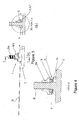
- the resilient deformable member 3 has a first electrically conductive portion 4 as seen in Figure 4 .
- This in the assembly shown is on the lower part of the resilient deformable member 3.
- the first electrically conductive portion may be on the upper or a middle part of the resilient deformable member, for example in use as a capacitive circuit.
- the first electrically conductive portion may be adjacent, and not part of the resilient deformable member. When the first conductive portion and the resilient deformable member are adjacent there may be an air gap (for example for capacitive sensing), spacer or other element/s placed between them.
- the first electrically conductive portion 4 may be a lower portion of the member 3 that is conductive.
- the electrically conductive portion 4 may contact the contact sensing member 5, for example on a second electrically conductive portion 6 as shown in Figure 6 or the portion and member may be separated by another element, such as an electrical insulator (for example when capacitive or inductive sensing is used).
- an electrical insulator for example when capacitive or inductive sensing is used.
- the material is an elastomer it may be doped, for example with carbon to make that lower portion conductive to therefore form the first conductive portion 4.
- it When it is the lower form and in contact with the second conductive portion 6 it may be used for resistive sensing of tampering.
- it When it is on the upper portion (whether unitary or separate) then it may be part of a capacitive sensing or inductive sensing.
- the material may be silicon doped with ferrite to act as, for instance, a magnetic core.
- the deformable member 3 may act as a way to exert pressure (and therefore vary it on tampering) and other electrical components to form the impedance circuit may be located against it.
- the upper portion and remainder of the member 3 that is not in contact with the contact sensing member 5 is not conductive. This may insulate the circuit from the effects of any wear of the housing 9.
- the member 3 is an endless member, but can be formed as necessary to fit the desired application.
- the contact sensing member 5 is shown in Figure 2 (and Figure 6 ) has at least one second electrically conductive portion 6 at the head 14.
- it has two such portions a second 6 and third 7 (or more) on a top surface, which are diametrically opposed, to allow for example electrical contact with the first conductive portion 4 when there is resistive sensing.
- the portions may be below the surface (for example when physical electrical contact with deformable member 3 is not required, for example in capacitive or inductive sensing).
- the portions may cover conforms to the shape of the resilient deformable member 3 it locates against but is not necessarily so. Therefore in the example shown in Figure 2 the head 14 is also shown as an endless member.
- the head 14 of the contact sensing member 5 where it locates with the resilient deformable member 3 may be shaped as needed for the intended application.
- the tail 15 extends from the head 14 of the contact sensing member 5 as shown in Figure 2 .
- the tail 15 contains circuit traces 16 which go to one each to the second electrically conductive portion 6 and third electrically conductive portion 7. Traces 16 then connect out and at the end of the tail 15 for connection to sensing equipment 17.
- the sensing equipment can be locally contained within the piece of equipment 12 which is being protected, and in addition may send signals locally for alerts or may send them remotely from the piece of equipment 12.
- the sensing equipment 17 may send a local alert for example a flashing light or otherwise, and may also or instead send a signal to a remote sensing station to sound an alarm to indicate tampering with the equipment.
- the contact sensing member or members may comprise additional electrical contacts.
- the electrical contacts may be provided on a backing layer.
- the backing layer may provide support or encourage the contacts into appropriate positions. In a preferred embodiment these contacts will comprise a part of a printed wire board.
- the printed wire board may be rigid, flexible or comprise both rigid and flexible sections. In the following description it should be realised that reference to a printed wire board or other backing layer material encompasses a broad range of backing layers, flexible, rigid or otherwise.
- the contact sensing member 5 is a flexible printed circuit with exposed conductive portions forming the second electrically conductive portion 6 and third electrically conductive portion 7. Some, or all, of the areas of the flexible printed circuit may also be reinforced. This may help to insert it into equipment and/or for mounting purposes.
- a rigid printed wiring board may be used, for instance to provide a more resilient member.
- the total impedance of the circuit formed in conjunction with the first resilient deformable member 3 when in contact with the contact sensing member 5 is within a known range and any deviation may cause an alarm.
- the impedance of an immediate physical contact between a resilient deformable member 3 having a first electrically conductive portion 4 against at least the second electrically conductive portion 6 and preferably third electrically conductive portion 7 is within a known range, and any deviation again, may cause an alarm.
- the impedance of an electrical relationship between a first electrically conductive portion 4 adjacent or on said resilient deformable member 3 and a second electrically conductive portion 6 and possibly a third electrically conductive portion 7 is within a known range, and any deviation again, may cause an alarm.
- the total impedance of the circuit formed in conjunction with the first resilient deformable member 3 when in contact with the contact sensing member 5 is within a known range and any deviation may cause an alarm.
- the change in the total impedance of the circuit formed may be due to a change electrical relationship between the members 3, 5.
- the capacitance between the resilient deformable member 3 and its first electrically conductive portion 4 and at least the second electrically conductive portion 6 and preferably third electrically conductive portion 7 is within a known range, and any deviation again, may cause an alarm.
- the capacitance of two conductive areas will change if the distance or pressure between those areas or their spatial relationship is altered.
- a straightforward example of this is a parallel plate capacitor.
- the inductance between the resilient deformable member 3 and its first electrically conductive portion 4 and at least the second electrically conductive portion 6 and preferably the third electrically conductive portion 7 is within a known range, and any deviation due to a change in pressure or relative movement, may cause an alarm.
- the resilient deformable member 3 may comprise a coil and the movement of the first electrically conductive portion 4 may change the inductance apparent to the first electrically conductive member and a second portion 6.
- the resistance of a path through the electrically conductive portion 7 of the resilient deformable member 3 and at least the second electrically conductive portion 6 and preferably the third conductive portion 7 is within a known range, and any deviation due to a change in pressure or relative movement may cause an alarm.
- contact could be made between the conductive portions forming a small circuit between the second and third conductive portions, alternatively this may be a capacitive or inductive circuit as shown in Figure 9 .
- the total measured impedance may include a combination of resistance, capacitance or inductance, in combination or as separate measurements.
- Figure 9 demonstrates further methods of creating measureable impedance. It will be clear to the reader that these are only example methods and may be combined or alternative methods may be used.
- a measurement may be of the resistance between a first electrically conductive portion 4 (which in the preferred embodiment is part of the deformable member 3), adjacent to the resilient deformable member 3, in physical contact with a second electrically conductive portion 6 below the member.
- a third electrically conductive portion 7 may be present on the contact sensing member, or elsewhere. This portion may allow a circuit to be formed between the first, second and third contact members for sensing.
- the first conductive portion may be on (part of) the resilient deformable member 3.
- Figures 9c and 9d demonstrate alternative embodiments which may measure capacitive impedance.
- Figure 9c shows a first electrically conductive member 4 and a second electrically conductive member 6 separated by a (or part of a) resilient deformable member 3.
- the member 3 acts as a dielectric between the two conductive portions and movement of the resilient deformable member will result in a change in the level of capacitance of the electrical relationship between the portions.
- a further embodiment is shown where a third electrically conductive portion 7 is present, located on the contact sensing member 6.
- first electrically conductive portion 4 may be adjacent to the resilient deformable member 3 - placed directly above or separated by an air-gap or intermediate layer - or the first electrically conductive portion 4 may be on (part of or encapsulated by) the resilient deformable member 3.
- Figures 9e and 9f demonstrate further alternative embodiments which may measure inductive impedance.
- Figure 9e shows a system in which first 4 and second 6 electrically conductive members may be coils or loops.
- the resilient deformable member 3 may comprise a silicon doped ferrite core to increase the effect of any tamper induced deformation, or may be separate thereto, and simply hold the core proximate the coils. Tamper induced deformation may be measured by the change in inductance between the conductive portions.
- the conductive members may be wound around areas of the tamper detection element as would be known by one skilled in the art.
- Figure 9f shows a further embodiment where both the first 4 and second 6 electrically conductive portions are located on the contact sensing member.
- the resilient deformable member 3 may be doped with ferrite (or support a separate core) so as to provide a magnetically permeable core to improve coupling between the conductive portions.
- circuit traces may also be present in the printed wire board for redundancy or other purposes.
- the tamper detection element 1 also has a housing 9.
- the housing is designed to contain the contact sensing member and the resilient deformable member and ensure appropriate contact and positioning between them. It can also serve to protect the members 3 and 5 to prevent tampering with them.
- the housing is hollowed out in the direction towards the resilient deformable member 3 and contact sensing member 5 to at least receive the head 14 of the contact sensing member 5 and a substantial part of the resilient deformable member 3.
- the housing 9 may also have one or more engaging features 19 to provide engagement and holding with a tool (not shown).
- the engaging features 19 are flat as shown on a side wall and opposing side wall of the housing 9 for holding by pliers or a spanner or similar tool.
- the housing may be substantially larger than the contact sensing member 5.
- the additional space in the housing may contain a printed wire board.
- the printed wire board may comprise further security features and/or may comprise an interface between the contact sensing member 5 and the tail 15.
- the printed wire board may be shaped to fit in a hollow region of the housing.
- the shape of the housing may provide means to easily remove or attach the device.
- the tail 15 may be detachable from the housing, in some cases allowing easier installation.
- the housing may be hollowed out in the direction towards the resilient deformable member 3, allowing contact or close proximity between resilient deformable member 3 and the contact sensing member 5.
- the housing 9 is preferably made from a resilient material. This material may be similar to that used for the second member 8, in the embodiment shown this may be stainless steel or a similar metal. In a preferred embodiment the material may be a resilient plastic, for example the plastic may be PVC. As shown in Figure 2 the housing 9 is an endless member and is contoured to conform with those parts of the contact sensing member 5 and resilient deformable member 3 which reside therein. In a particular embodiment the housing may appear substantially rectangular. The rectangle may have rounded corners to contour to a second member 8 it is attached to. The end of the rectangle distal from the second member 8 may have substantially sharp corners and may comprise the tail 15, or the attachment means for the tail 15.
- FIG. 3a, 3b and 4 An embodiment of the assembly of the tamper detection element 1 is shown in Figures 3a, 3b and 4 .
- a first member 2 to which the tamper detection element 1 is attached.
- the second member is a threaded fastener 8a together with a nut 8b thereon.
- the contact sensing member 5 is assembled with the housing 9 (though typically this will be preassembled and come as a sub assembly) together with the resilient deformable member 3.
- the resiliently deformable member may already be held captive in the housing or maybe assembled with it as required.
- the tamper detection element 1 is then located in the example shown over the threaded fastener 8a and if necessary if not assembled beforehand the resiliently deformable member 3 is then located there over and into the appropriate cavity in the housing 9.
- the securing nut 8b is done up over the thread fastener 8a to lock the assembled tamper detection element 1 in place.
- the resiliently deformable member 3 is squashed between the second member 8 (in this case the threaded fastener 8a and nut 8b) and the contact sensing member 5.
- Shown in Figure 4 also is the first electrically conductive portion 4 of the resilient deformable member 3.
- the first electrically conductive portion 4 is held against the second electrically conductive portion 6 and in the preferred embodiment the third electrically conductive portion 7.
- a voltage or current is applied to the second electrically conductive portion 6 a circuit is formed across to the third electrically conductive portion 7 via the first electrically conductive portion 4.
- an AC current or voltage may be used.
- the degree of pressure of the first electrically conductive portion 4 will vary the impedance between the second and third electrically conductive portions 6 and 7 respectively. This effect, caused by the tamper induced deformation of the resilient deformable member 3 may be enhanced by appropriate selection of the resilient deformable member 3 material.
- a base reading can be taken and thereafter variance in this base reading, for example the total impedance of the circuit, outside of certain thresholds will indicate that tampering is occurring, for example the distance between the first member 2 and second member 8 is changing.
- an unauthorised user may be undoing the nut at 8b which will then reduce the pressure of the resilient deformable member 3 against the contact sensing member 5 thus resulting in an increased impedance of this circuit. Once this exceeds the threshold value then an alarm or tampering event will be triggered.
- the circuit may be formed and measured between the first electrically conductive portion 4 and the second electrically conductive portion 6 only.
- first electrically conductive portion 4 there may not be direct contact between the first electrically conductive portion 4 and the second electrically conductive portion 6.
- a capacitance may be measured and the pressure between the resilient deformable member and the contact sensing member 5 will alter the relationship between the members and the impedance will change.
- the resilient deformable member 3 will "ooze" out the hole that is formed and reduce the pressure of the portion 4 against, or proximate the portion or portions 6 and 7 and therefore again vary the impedance of the circuit.
- the resilient deformable member is adapted to allow this tamper induced deformation.
- the material used for the resilient deformable member may be selected to enhance characteristics of the tamper induced deformation. This is shown in Figure 5 , where part of the housing 9A has been broken away. This again will once a threshold is exceeded result in an alarm or tamper alert.
- the first member 2 is a mounting plate and this for example could be the plate of a piece of equipment through which the second member 8b as a threaded member is passed there through to hold for example a further piece of equipment against the first member 2 and when an attempt is made to remove or alter any of the pieces of equipment by tampering with the tamper detection element 1 an alarm will result.
- any attempt to create relative movement between the first member 2 and second member 8 (or elements 8a or 8b) will result in a reduced or varied impedance of the circuit and again once the threshold is exceeded an alarm will sound.
- the tamper detection element may be connected to a separate measurement device, preferably through a connecting wire or cable.
- the tail 15 is preferably a flat cable and may contain further traces or security devices. In a preferred embodiment this is a flat USB cable.
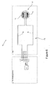
- Figure 6 shows an embodiment of this connection using a 5 wire cable.
- separate electrical connection is made to each of the electrically conductive portions 6 and 7.
- a single electrical connection may be used, particularly if measuring the impedance or capacitance.
- further electrical connections may be used or further tracks may be present on the tail or measuring device for signal noise reduction or security means.
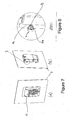
- FIGs 7a, b and Figure 8 Such an assembly is shown in Figures 7a, b and Figure 8 where a piece of equipment 12 in this case a security key pad is held to a plate or first member 2 via a threaded fastener as the second member 8. Any attempt for example to undo the security nut 8b will result in a varied impedance of the circuit and sound an alarm.
- the tail 15 on the contact sensing member 5 can be seen and in this case it is loomed into the internal parts of the piece of equipment 12.
- the tamper detection element 1 may locate between a first member 2 and second member 8 for example as two plates or portions of a cabinet and when relative movement between the two portions occurs pressure is increased or decreased on the tamper detection element and therefore the resulting impedance in the circuit will vary.
- the tamper detection element 1 may be in cased or packaged to retain all parts therein and may have some form of adhesive mounting or similar to mount it to one of the two members 2 or 8 and again a base reading taken when the two members are at the correct relationship with each other.
- the equipment 12 to be protected may be assembled with the tamper detection elements 1 as part of its assembly process or the tamper detection elements 1 may be retrofitted to the equipment 12 either on site or as part of the maintenance of the equipment 12.
- detection element there is a plurality of detection elements and these may be arrayed throughout the equipment 12 being protected.
- the detection element may also be provided as a kit of parts, to provide one or more tamper detection elements, for example to equipment 12 assemblers or maintainers for pre or post fitting thereto.
Landscapes
- Engineering & Computer Science (AREA)
- General Engineering & Computer Science (AREA)
- Physics & Mathematics (AREA)
- General Physics & Mathematics (AREA)
- Mechanical Engineering (AREA)
- Burglar Alarm Systems (AREA)
Description
- The present invention relates to tamper evident systems. In particular, though not solely, the present invention is directed to tamper evident devices, their methods of use and manufacture to detect unauthorised tampering of fasteners, or devices held in place by fasteners.
- There is increased use of systems that are remotely monitored. These systems may only occasionally be visited by human operators. Such systems may be remote in their location, or may be in everyday situations, for example in households, commercial premises, or urban or town environments.
- The reasons these systems may rarely see human operators is because they may be numerous in number and therefore the cost of regular visits may be too high, or may be too remote to regularly visit. The systems themselves tend to be stable and will easily run for long periods of time with no need for a human operator on site.
- Such systems however, because they may be in dense population areas may be the target of attempted theft, vandalism or other abuse which may compromise the system itself, or at least the cabinet, components, for example key pad or similar the system and equipment is contained in. The lack of regular human visits makes detection of such tampering difficult.
- Examples of such systems are household and commercial power meters. These can now be easily monitored from the central control of the power company and thus there is no need to visit such equipment to take meter readings as there has been in the past. Moreover, there is a need to ensure such meters are not tampered with due to the cost of such meters and also the loss of revenue if such meters do not read correctly.
- There may also be systems that are regularly visited, but their equipment or content may be mission critical (for example traffic light systems), of high value (for example currency vending machines), or that otherwise require confidence in their integrity and security (for example EFTPOS payment machines).
- Tamper detection is also valuable for a computer or electronics suite. For example, it may allow an alert to occur if a person attempts to gain access to the internal units or remove device components. Equipment that has key pads, security card readers, or credit card and EFTPOS machine readers can often be tampered with to remove and replace the content with the tamperer's own equipment. This, for example, would direct funds to the tamperer's account instead of the correct account. Other tampering may involve insertion of information scanning systems to allow capture of a user's information, for example security keypad entry, credit card or EFTPOS card details.
- There is also a need for a device which can detect the loosening of, for example, fasteners or other components relative to each other. Such loosening may occur due to tampering, but may also occur due to general wear and tear, vibration and movement, and the weather.
- An example of a prior art solution is that found in
US 6,774,807 of Lehfeldt et al. This discloses a fastener that utilises a magnetic switch or micro-switch in the fastener or against the fastener periphery that activates when the fastener is turned through a certain angle. These switches are actuated by a mechanical system that must be in close proximity to the fastener, or utilise a magnetic pickup and associated components. As such they require extra systems and components and specially designed and shaped fasteners. -
WO03/005334 US5,488,206 each disclose a 'joystick' user interface arrangement for manipulation by a user.US2006/0048582 discloses a load cell arrangement for detecting a person sitting in a seat in a vehicle.US2002/0014962 describes a tamper resistant enclosure for protecting an electronic device. The enclosure includes an external cover and an internal cover. Four screws (one at each corner) secure the internal cover to the device and the external cover by means of standoffs. A washer is interposed between the device and the standoff. The device has a dielectric substrate with a metal pad around each hole for ensuring the electrical connection to ground through the washer, the standoff and the conductive body of the external cover. When one of the screws is at least partially removed and the internal cover is moved, the circuit is interrupted and the system assumes that a tampering is being attempted. -
WO 2006/092591 shows an anti-tamper device for detecting relative movement between a part having a stud clamped to a mounting by a nut. - In this specification where reference has been made to patent specifications, other external documents, or other sources of information, this is generally for the purpose of providing a context for discussing the features of the invention. Unless specifically stated otherwise, reference to such external documents is not to be construed as an admission that such documents, or such sources of information, in any jurisdiction, are prior art, or form part of the common general knowledge in the art.
- It is therefore an object of the present invention to provide an improved tamper evident system, or to overcome the above shortcomings or address the above desiderata, or to at least provide the public with a useful choice.
- In a first aspect the present invention consists in a tamper detection element, as claimed.
- In a second aspect the present invention consists in a method of detecting unauthorised tampering with a fastener or a device held to a first member by the fastener, as claimed.
- As used herein the term "and/or" means "and" or "or", or both.
- As used herein "(s)" following a noun means the plural and/or singular forms of the noun.
- The term "comprising" as used in this specification means "consisting at least in part of". When interpreting statements in this specification which include that term, the features, prefaced by that term in each statement, all need to be present, but other features can also be present. Related terms such as "comprise" and "comprised" are to be interpreted in the same manner.
- To those skilled in the art to which the invention relates, many changes in construction and widely differing embodiments and application of the invention will suggest themselves without departing from the scope of the invention as defined in the appended claims. The disclosures and the descriptions herein are purely illustrative and are not intended to be in any sense limiting.
- Other aspects of the invention may become apparent from the following description which is given by way of example only and with reference to the accompanying drawings.
- Preferred forms of the present invention will now be described with reference to the accompanying drawings in which;
- Figure 1
- shows an external isometric view of an embodiment of the tamper detecting element mounted to a threaded member on part of a piece of equipment,
- Figure 2
- shows an exploded view of
Figure 1 , - Figure 3
- (A) shows a side view of
Figure 1 , - Figure 3
- (B) shows a cross section along line AA of
Figure 3A , - Figure 4
- shows Detail B from
Figure 3(B) , - Figure 5
- close up showing pill deforming out of housing,
- Figure 6
- is a circuit diagram for the tamper detecting element,
- Figure 7
- (A) is an isometric external view of equipment with tamper detecting element(s) located thereon,
- Figure 7
- (B) is an isometric internal view of
Figure 7(A) , - Figure 8
- Shows Detail C from
Figure 7(B) , and - Figure 9
- Shows various circuits in which the present invention uses impedance to sense tampering, with (9A) showing a single resistive circuit across one portion of the resilient deformable member (for example a (first) electrically conductive portion (for example on the deformable member) onto a single pad as a further (second) electrically conductive portion), (9B) showing a double resistive circuit with two or more sensed resistive portions (for example a (first) electrically conductive portion of the deformable member onto a first pad as the (second) electrically conductive portion and a second pad as the third electrically conductive portion), (9C) showing a single capacitive circuit across the resilient deformable member (for example a (first) electrically conductive portion of the deformable member spaced by off from a single pad (for example by a non-conductive portion of the deformable member to act as a dielectric) as a further (second) electrically conductive portion), (9D) showing a dual capacitive circuit of (9C), (9E) showing a single inductive circuit across one side of the deformable member where the member has a ferrite or similar core, and (9F) showing a dual inductive circuit of (9E).
- Preferred embodiments will now be described with reference to
Figures 1 through 9 . - The
tamper detection element 1 is shown inFigures 1 and2 held to afirst member 2 by asecond member 8. In this instance thesecond member 8 is comprised of a threaded fastener 8A and anut 8B engaged thereon. There are several ways in which theelement 1 can perform its task, and in the preferred embodiment it is sandwiched between a first member and a second member. A fastener is just one example of how it can be held in place, other methods can also be used, such as sandwiching between a first member and a second member which may be a planar surface such as a wall or door. For example the fastener 8A andnut 8B inFigures 3 and 4 may not be present, but rather thesecond member 8 is a surface of a cabinet or door sandwiching theelement 1 in place. - The
element 1 consists of a resilientdeformable member 3 which when the element is secured in place is held down against or in proximity to acontact sensing member 5. In practice the resilientdeformable member 3 is made from an elastomer such as silicon or rubber (natural or synthetic). According to the invention there is present ahousing 9, to at least in part contain themembers element 1 relies on change in pressure on the element to vary the impedance of the element. - The relationship between the resilient
deformable member 3 and thecontact sensing member 5 will determine if a tamper is occurring. The tamper detection may comprise an electrical circuit connected to tamperdetection element 1. The electrical circuit may measure the impedance, or its variation, of the circuit, for example of the resilientdeformable member 3 and the contact sensing members. The impedance measured may comprise one of, or a combination of, resistive, capacitive or inductive components. - In one embodiment as a resistive circuit the resilient
deformable member 3 has a first electricallyconductive portion 4 as seen inFigure 4 . This in the assembly shown is on the lower part of the resilientdeformable member 3. In an alternative embodiment the first electrically conductive portion may be on the upper or a middle part of the resilient deformable member, for example in use as a capacitive circuit. In a further alternative embodiment the first electrically conductive portion may be adjacent, and not part of the resilient deformable member. When the first conductive portion and the resilient deformable member are adjacent there may be an air gap (for example for capacitive sensing), spacer or other element/s placed between them. - The first electrically
conductive portion 4 may be a lower portion of themember 3 that is conductive. The electricallyconductive portion 4 may contact thecontact sensing member 5, for example on a second electricallyconductive portion 6 as shown inFigure 6 or the portion and member may be separated by another element, such as an electrical insulator (for example when capacitive or inductive sensing is used). For example when the material is an elastomer it may be doped, for example with carbon to make that lower portion conductive to therefore form the firstconductive portion 4. When it is the lower form and in contact with the secondconductive portion 6 it may be used for resistive sensing of tampering. When it is on the upper portion (whether unitary or separate) then it may be part of a capacitive sensing or inductive sensing. In a further example the material may be silicon doped with ferrite to act as, for instance, a magnetic core. In other forms, thedeformable member 3 may act as a way to exert pressure (and therefore vary it on tampering) and other electrical components to form the impedance circuit may be located against it. However, there will be other methods known in the art for other materials that may also suffice. Preferably the upper portion and remainder of themember 3 that is not in contact with thecontact sensing member 5 is not conductive. This may insulate the circuit from the effects of any wear of thehousing 9. As shown inFigure 2 themember 3 is an endless member, but can be formed as necessary to fit the desired application. - The
contact sensing member 5 is shown inFigure 2 (andFigure 6 ) has at least one second electricallyconductive portion 6 at thehead 14. In the preferred form shown inFigure 2 it has two such portions a second 6 and third 7 (or more) on a top surface, which are diametrically opposed, to allow for example electrical contact with the firstconductive portion 4 when there is resistive sensing. Alternatively the portions may be below the surface (for example when physical electrical contact withdeformable member 3 is not required, for example in capacitive or inductive sensing). The portions may cover conforms to the shape of the resilientdeformable member 3 it locates against but is not necessarily so. Therefore in the example shown inFigure 2 thehead 14 is also shown as an endless member. However, in other embodiments thehead 14 of thecontact sensing member 5 where it locates with the resilientdeformable member 3 may be shaped as needed for the intended application. - The
tail 15 extends from thehead 14 of thecontact sensing member 5 as shown inFigure 2 . Thetail 15 contains circuit traces 16 which go to one each to the second electricallyconductive portion 6 and third electricallyconductive portion 7.Traces 16 then connect out and at the end of thetail 15 for connection to sensingequipment 17. The sensing equipment can be locally contained within the piece ofequipment 12 which is being protected, and in addition may send signals locally for alerts or may send them remotely from the piece ofequipment 12. For example thesensing equipment 17 may send a local alert for example a flashing light or otherwise, and may also or instead send a signal to a remote sensing station to sound an alarm to indicate tampering with the equipment. - The contact sensing member or members may comprise additional electrical contacts. The electrical contacts may be provided on a backing layer. The backing layer may provide support or encourage the contacts into appropriate positions. In a preferred embodiment these contacts will comprise a part of a printed wire board. The printed wire board may be rigid, flexible or comprise both rigid and flexible sections. In the following description it should be realised that reference to a printed wire board or other backing layer material encompasses a broad range of backing layers, flexible, rigid or otherwise. In one embodiment the
contact sensing member 5 is a flexible printed circuit with exposed conductive portions forming the second electricallyconductive portion 6 and third electricallyconductive portion 7. Some, or all, of the areas of the flexible printed circuit may also be reinforced. This may help to insert it into equipment and/or for mounting purposes. In a further embodiment a rigid printed wiring board may be used, for instance to provide a more resilient member. In a preferred embodiment the total impedance of the circuit formed in conjunction with the firstresilient deformable member 3 when in contact with thecontact sensing member 5 is within a known range and any deviation may cause an alarm. - In one embodiment the impedance of an immediate physical contact between a resilient
deformable member 3 having a first electricallyconductive portion 4 against at least the second electricallyconductive portion 6 and preferably third electricallyconductive portion 7 is within a known range, and any deviation again, may cause an alarm. In an alternative embodiment the impedance of an electrical relationship between a first electricallyconductive portion 4 adjacent or on said resilientdeformable member 3 and a second electricallyconductive portion 6 and possibly a third electricallyconductive portion 7 is within a known range, and any deviation again, may cause an alarm. In this alternative embodiment there may not be contact between all or any of theconductive portions - In an alternative embodiment the total impedance of the circuit formed in conjunction with the first
resilient deformable member 3 when in contact with thecontact sensing member 5 is within a known range and any deviation may cause an alarm. The change in the total impedance of the circuit formed may be due to a change electrical relationship between themembers deformable member 3 and its first electricallyconductive portion 4 and at least the second electricallyconductive portion 6 and preferably third electricallyconductive portion 7 is within a known range, and any deviation again, may cause an alarm. For instance the capacitance of two conductive areas will change if the distance or pressure between those areas or their spatial relationship is altered. A straightforward example of this is a parallel plate capacitor. In a further example the inductance between the resilientdeformable member 3 and its first electricallyconductive portion 4 and at least the second electricallyconductive portion 6 and preferably the third electricallyconductive portion 7 is within a known range, and any deviation due to a change in pressure or relative movement, may cause an alarm. For instance, the resilientdeformable member 3 may comprise a coil and the movement of the first electricallyconductive portion 4 may change the inductance apparent to the first electrically conductive member and asecond portion 6. In a further example the resistance of a path through the electricallyconductive portion 7 of the resilientdeformable member 3 and at least the second electricallyconductive portion 6 and preferably the thirdconductive portion 7 is within a known range, and any deviation due to a change in pressure or relative movement may cause an alarm. In a simple example contact could be made between the conductive portions forming a small circuit between the second and third conductive portions, alternatively this may be a capacitive or inductive circuit as shown inFigure 9 . The total measured impedance may include a combination of resistance, capacitance or inductance, in combination or as separate measurements. -
Figure 9 demonstrates further methods of creating measureable impedance. It will be clear to the reader that these are only example methods and may be combined or alternative methods may be used. Looking first atFigure 9a , a measurement may be of the resistance between a first electrically conductive portion 4 (which in the preferred embodiment is part of the deformable member 3), adjacent to the resilientdeformable member 3, in physical contact with a second electricallyconductive portion 6 below the member. In an alternative resistive embodiment (figure 9b ) a third electricallyconductive portion 7 may be present on the contact sensing member, or elsewhere. This portion may allow a circuit to be formed between the first, second and third contact members for sensing. In some embodiments the first conductive portion may be on (part of) the resilientdeformable member 3. -
Figures 9c and 9d demonstrate alternative embodiments which may measure capacitive impedance.Figure 9c shows a first electricallyconductive member 4 and a second electricallyconductive member 6 separated by a (or part of a)resilient deformable member 3. In this embodiment themember 3 acts as a dielectric between the two conductive portions and movement of the resilient deformable member will result in a change in the level of capacitance of the electrical relationship between the portions. Infigure 9d a further embodiment is shown where a third electricallyconductive portion 7 is present, located on thecontact sensing member 6. In this embodiment the first electricallyconductive portion 4 may be adjacent to the resilient deformable member 3 - placed directly above or separated by an air-gap or intermediate layer - or the first electricallyconductive portion 4 may be on (part of or encapsulated by) the resilientdeformable member 3. -
Figures 9e and 9f demonstrate further alternative embodiments which may measure inductive impedance.Figure 9e shows a system in which first 4 and second 6 electrically conductive members may be coils or loops. The resilientdeformable member 3 may comprise a silicon doped ferrite core to increase the effect of any tamper induced deformation, or may be separate thereto, and simply hold the core proximate the coils. Tamper induced deformation may be measured by the change in inductance between the conductive portions. In alternative embodiments the conductive members may be wound around areas of the tamper detection element as would be known by one skilled in the art.Figure 9f shows a further embodiment where both the first 4 and second 6 electrically conductive portions are located on the contact sensing member. The resilientdeformable member 3 may be doped with ferrite (or support a separate core) so as to provide a magnetically permeable core to improve coupling between the conductive portions. - Other circuit traces may also be present in the printed wire board for redundancy or other purposes.
- The
tamper detection element 1 also has ahousing 9. The housing is designed to contain the contact sensing member and the resilient deformable member and ensure appropriate contact and positioning between them. It can also serve to protect themembers Figure 4 the housing is hollowed out in the direction towards the resilientdeformable member 3 andcontact sensing member 5 to at least receive thehead 14 of thecontact sensing member 5 and a substantial part of the resilientdeformable member 3. In a preferred form of thehousing 9 there is asmall aperture 18 in a side wall to allow thetail 15 to be passed there through and may also be an internal relief to help retain at least thehead 14 of thecontact sensing member 5. Thehousing 9 may also have one or more engaging features 19 to provide engagement and holding with a tool (not shown). For example inFigure 2 the engaging features 19 are flat as shown on a side wall and opposing side wall of thehousing 9 for holding by pliers or a spanner or similar tool. In a second preferred embodiment board the housing may be substantially larger than thecontact sensing member 5. The additional space in the housing may contain a printed wire board. The printed wire board may comprise further security features and/or may comprise an interface between thecontact sensing member 5 and thetail 15. The printed wire board may be shaped to fit in a hollow region of the housing. The shape of the housing may provide means to easily remove or attach the device. In this embodiment thetail 15 may be detachable from the housing, in some cases allowing easier installation. As in the previous embodiment the housing may be hollowed out in the direction towards the resilientdeformable member 3, allowing contact or close proximity between resilientdeformable member 3 and thecontact sensing member 5. - The
housing 9 is preferably made from a resilient material. This material may be similar to that used for thesecond member 8, in the embodiment shown this may be stainless steel or a similar metal. In a preferred embodiment the material may be a resilient plastic, for example the plastic may be PVC. As shown inFigure 2 thehousing 9 is an endless member and is contoured to conform with those parts of thecontact sensing member 5 and resilientdeformable member 3 which reside therein. In a particular embodiment the housing may appear substantially rectangular. The rectangle may have rounded corners to contour to asecond member 8 it is attached to. The end of the rectangle distal from thesecond member 8 may have substantially sharp corners and may comprise thetail 15, or the attachment means for thetail 15. - An embodiment of the assembly of the
tamper detection element 1 is shown inFigures 3a, 3b and 4 . In the assembly shown there is afirst member 2 to which thetamper detection element 1 is attached. In the assembly shown the second member is a threaded fastener 8a together with a nut 8b thereon. In assembling thecontact sensing member 5 is assembled with the housing 9 (though typically this will be preassembled and come as a sub assembly) together with the resilientdeformable member 3. Again the resiliently deformable member may already be held captive in the housing or maybe assembled with it as required. Thetamper detection element 1 is then located in the example shown over the threaded fastener 8a and if necessary if not assembled beforehand the resilientlydeformable member 3 is then located there over and into the appropriate cavity in thehousing 9. The securing nut 8b is done up over the thread fastener 8a to lock the assembledtamper detection element 1 in place. As can be seen inFigure 4 the resilientlydeformable member 3 is squashed between the second member 8 (in this case the threaded fastener 8a and nut 8b) and thecontact sensing member 5. - Shown in
Figure 4 also is the first electricallyconductive portion 4 of the resilientdeformable member 3. As can be seen the first electricallyconductive portion 4 is held against the second electricallyconductive portion 6 and in the preferred embodiment the third electricallyconductive portion 7. When a voltage or current is applied to the second electrically conductive portion 6 a circuit is formed across to the third electricallyconductive portion 7 via the first electricallyconductive portion 4. In some cases an AC current or voltage may be used. The degree of pressure of the first electricallyconductive portion 4 will vary the impedance between the second and third electricallyconductive portions deformable member 3 may be enhanced by appropriate selection of the resilientdeformable member 3 material. Therefore once thetamper detection element 1 is assembled a base reading can be taken and thereafter variance in this base reading, for example the total impedance of the circuit, outside of certain thresholds will indicate that tampering is occurring, for example the distance between thefirst member 2 andsecond member 8 is changing. For example an unauthorised user may be undoing the nut at 8b which will then reduce the pressure of the resilientdeformable member 3 against thecontact sensing member 5 thus resulting in an increased impedance of this circuit. Once this exceeds the threshold value then an alarm or tampering event will be triggered. In other embodiments less preferable the circuit may be formed and measured between the first electricallyconductive portion 4 and the second electricallyconductive portion 6 only. In an alternative embodiment there may not be direct contact between the first electricallyconductive portion 4 and the second electricallyconductive portion 6. In this case a capacitance may be measured and the pressure between the resilient deformable member and thecontact sensing member 5 will alter the relationship between the members and the impedance will change. - Further should the
housing 9 be tampered with, for example drilling in from the side or similar attempt at removal or tampering with the circuit the resilientdeformable member 3 will "ooze" out the hole that is formed and reduce the pressure of theportion 4 against, or proximate the portion orportions Figure 5 , where part of thehousing 9A has been broken away. This again will once a threshold is exceeded result in an alarm or tamper alert. - In the embodiment shown the
first member 2 is a mounting plate and this for example could be the plate of a piece of equipment through which the second member 8b as a threaded member is passed there through to hold for example a further piece of equipment against thefirst member 2 and when an attempt is made to remove or alter any of the pieces of equipment by tampering with thetamper detection element 1 an alarm will result. For example any attempt to create relative movement between thefirst member 2 and second member 8 (or elements 8a or 8b) will result in a reduced or varied impedance of the circuit and again once the threshold is exceeded an alarm will sound. - The tamper detection element may be connected to a separate measurement device, preferably through a connecting wire or cable. The
tail 15 is preferably a flat cable and may contain further traces or security devices. In a preferred embodiment this is a flat USB cable.Figure 6 shows an embodiment of this connection using a 5 wire cable. In this embodiment separate electrical connection is made to each of the electricallyconductive portions - Such an assembly is shown in
Figures 7a, b and Figure 8 where a piece ofequipment 12 in this case a security key pad is held to a plate orfirst member 2 via a threaded fastener as thesecond member 8. Any attempt for example to undo the security nut 8b will result in a varied impedance of the circuit and sound an alarm. InFigure 8 thetail 15 on thecontact sensing member 5 can be seen and in this case it is loomed into the internal parts of the piece ofequipment 12. In other embodiments thetamper detection element 1 may locate between afirst member 2 andsecond member 8 for example as two plates or portions of a cabinet and when relative movement between the two portions occurs pressure is increased or decreased on the tamper detection element and therefore the resulting impedance in the circuit will vary. In this application thetamper detection element 1 may be in cased or packaged to retain all parts therein and may have some form of adhesive mounting or similar to mount it to one of the twomembers - The
equipment 12 to be protected may be assembled with thetamper detection elements 1 as part of its assembly process or thetamper detection elements 1 may be retrofitted to theequipment 12 either on site or as part of the maintenance of theequipment 12. - In the preferred use of the present invention there is a plurality of detection elements and these may be arrayed throughout the
equipment 12 being protected. The detection element may also be provided as a kit of parts, to provide one or more tamper detection elements, for example toequipment 12 assemblers or maintainers for pre or post fitting thereto. - The foregoing description of the invention includes preferred forms thereof.
Claims (14)
- A tamper detection element (1) adapted at least in part to be held against a first member by a fastener (8) to detect unauthorised tampering with the fastener (8) or a device held to the first member by the fastener (8), the tamper detection element (1) comprising or including:a resilient deformable member (3) able to deform because of said tampering, the resilient deformable member at least in part comprising an elastomer or rubber,a rigid housing (9) to locate and contain said resilient deformable member (3) to said first member,a contact sensing member (5) disposed towards said resilient deformable member and substantially contained in said rigid housing (9);a first electrically conductive portion (4) adjacent or on said resilient deformable member (3), anda second electrically conductive portion (6) on said contact sensing member (5),wherein an electrical relationship can be formed between said first (4) and second (6) electrically conductive portions, and a tamper induced deformation of said resilient deformable member (3) varies the impedance of said electrical relationship, said variation indicative of said tampering to detect loosening of the fastener (8),and wherein the rigid housing (9) is an endless member and is contoured to conform to those parts of the contact sensing member and the resilient deformable member which reside therein, so that tampering with said rigid housing (9) also results in a tamper induced deformation of said resilient deformable member to vary the impedance of said electrical relationship indicative of said tampering.
- An element as claimed in claim 1 wherein in use the resilient deformable member (3) is held in compression.
- An element as claimed in any of claims 1 to 2 wherein said second electrically conductive portion (6) is disposed towards said first electrically conductive portion (4).
- An element as claimed in any one of claims 1 or 3 wherein a third electrically conductive portion (7) is on said contact sensing member (5) and said impedance is measured between said second (6) and third (7) electrically conductive portions.
- An element as claimed claim 4, wherein said impedance changes due to change in either or both a contact area or a pressure, between said first electrically conductive portion (4) and either or both of said second (6) and said third (7) electrically conductive portions.
- An element as claimed in any one of claims 1 to 5 wherein said element (1) is located between said first member and a second member to detect tampering as a relative movement therebetween.
- An element as claimed in claim 6, which is adapted to be held in place against said first member by said second member which is engaged with said first member.
- An element as claimed in any one of claims 1 to 7 wherein tampering with said rigid housing (9) also results in said deformation.
- A method of detecting unauthorised tampering with a fastener (8) or a device held to a first member by the fastener (8), comprising or including the steps of:providing a resilient deformable member (3) able to deform because of said tampering, the resilient deformable member at least in part comprising an elastomer or rubber;providing a contact sensing member (5) substantially contained in said rigid housing (9) and disposed towards said resilient deformable member (3);providing a first electrically conductive portion (4) adjacent or on said resilient deformable member (3),providing a second electrically conductive portion (6) on said contact sensing member (5);providing a rigid housing (9) to locate and substantially contain the resilient deformable member (3) and contact sensing member (5), wherein the rigid housing is an endless member and is contoured to conform to those parts of the contact sensing member and resilient deformable member which reside therein;connecting either or both said resilient deformable member (3) and/or said contact sensing member (5) to said first member by said fastener (8),forming an electrical relationship between said first (4) and second (6) electrically conductive portions;wherein a tamper induced deformation of said resilient deformable member (3) results in a variation in the impedance of said electrical relationship indicative of said tampering to detect loosening of the fastener (8);measuring said variation; anddeciding whether a tamper event has occurred or not.
- A method as claimed in claim 9 wherein the resilient deformable member (3) is, in use, held in compression said fastener.
- A method as claimed in either one of claims 9 to 10 wherein said decision of whether a tamper event has occurred includes the step of determining whether said change meets or exceeds a threshold.
- A method as claimed in any one of claims 9 to 11 wherein said method comprises the step of measuring a base reading of said impedance.
- A method as claimed in claim 12 wherein said method comprises periodically measuring said base reading of said impedance.
- A method as claimed in any one of claims 9 to 13 wherein said method comprises triggering an alert if said tamper event is detected.
Applications Claiming Priority (2)
| Application Number | Priority Date | Filing Date | Title |
|---|---|---|---|
| NZ60183612 | 2012-08-15 | ||
| PCT/NZ2013/000176 WO2014027905A1 (en) | 2012-08-15 | 2013-09-23 | Improvements in, or relating to, tamper evident systems |
Publications (3)
| Publication Number | Publication Date |
|---|---|
| EP2885774A1 EP2885774A1 (en) | 2015-06-24 |
| EP2885774A4 EP2885774A4 (en) | 2016-04-27 |
| EP2885774B1 true EP2885774B1 (en) | 2019-08-21 |
Family
ID=50685657
Family Applications (1)
| Application Number | Title | Priority Date | Filing Date |
|---|---|---|---|
| EP13869853.5A Not-in-force EP2885774B1 (en) | 2012-08-15 | 2013-09-23 | Improvements in, or relating to, tamper evident systems |
Country Status (4)
| Country | Link |
|---|---|
| US (1) | US9646472B2 (en) |
| EP (1) | EP2885774B1 (en) |
| AU (1) | AU2013303308C1 (en) |
| WO (1) | WO2014027905A1 (en) |
Families Citing this family (12)
| Publication number | Priority date | Publication date | Assignee | Title |
|---|---|---|---|---|
| US9911012B2 (en) | 2015-09-25 | 2018-03-06 | International Business Machines Corporation | Overlapping, discrete tamper-respondent sensors |
| EP3249634B1 (en) * | 2016-05-26 | 2024-05-15 | Nxp B.V. | Tamper detection device |
| US10299372B2 (en) | 2016-09-26 | 2019-05-21 | International Business Machines Corporation | Vented tamper-respondent assemblies |
| US10327329B2 (en) * | 2017-02-13 | 2019-06-18 | International Business Machines Corporation | Tamper-respondent assembly with flexible tamper-detect sensor(s) overlying in-situ-formed tamper-detect sensor |
| US10875503B2 (en) * | 2018-01-06 | 2020-12-29 | Toyota Motor Engineering & Manufacturing North America, Inc. | System and method for anti-theft control for autonomous vehicle |
| US10306753B1 (en) | 2018-02-22 | 2019-05-28 | International Business Machines Corporation | Enclosure-to-board interface with tamper-detect circuit(s) |
| US11665817B2 (en) | 2019-09-30 | 2023-05-30 | Block, Inc. | Tamper detection based on flexible member connecting circuitry elements |
| US10810570B1 (en) * | 2019-09-30 | 2020-10-20 | Square, Inc. | Point of sale device with cradle for mobile computing device |
| US11663368B2 (en) * | 2019-09-30 | 2023-05-30 | Block, Inc. | Tamper detection based on removal of fastener from recess |
| EP3840551A1 (en) * | 2019-12-20 | 2021-06-23 | ZKW Group GmbH | Car module |
| WO2025177191A1 (en) * | 2024-02-22 | 2025-08-28 | Sens-In S.R.L. | Monitoring system |
| IT202400003784A1 (en) * | 2024-02-22 | 2025-08-22 | Sens In S R L | MONITORING SYSTEM |
Citations (1)
| Publication number | Priority date | Publication date | Assignee | Title |
|---|---|---|---|---|
| WO2006092591A1 (en) * | 2005-03-01 | 2006-09-08 | Keymat Technology Limited | Anti-tampe devices |
Family Cites Families (38)
| Publication number | Priority date | Publication date | Assignee | Title |
|---|---|---|---|---|
| US3803577A (en) | 1971-04-06 | 1974-04-09 | W Peterson | Connection detection connector |
| US4329681A (en) | 1980-09-18 | 1982-05-11 | Parsons Zane W | Tamper sensor system |
| DE3110581A1 (en) | 1981-03-18 | 1982-12-30 | Hubert 8121 Haunshofen Hammerl | Switch arrangement for an electric alarm device |
| EP0195102B1 (en) | 1985-03-20 | 1989-06-28 | Winfred Klink | Electric contactor for monitoring a bolt screwed in a thread or a yielding material |
| FR2681134B1 (en) | 1991-09-05 | 1994-09-09 | Sagem | DEVICE FOR DETECTING THE OPENING OF AN APPARATUS. |
| GB9225654D0 (en) | 1992-12-08 | 1993-01-27 | Lussey David | Tamper detection sensor |
| US5488206A (en) | 1994-01-31 | 1996-01-30 | Wu; Donald | Joystick switch assembly |
| US5621387A (en) | 1995-08-08 | 1997-04-15 | Elk Products, Inc. | Box |
| JPH09159558A (en) | 1995-12-05 | 1997-06-20 | Hitachi Ltd | Fastened body |
| US5705981A (en) | 1996-03-15 | 1998-01-06 | Breed Automotive Technology, Inc. | Secure enclosure with continuous monitoring |
| US6087939A (en) | 1998-09-22 | 2000-07-11 | Se-Kure Controls, Inc. | Security system |
| US6054922A (en) | 1999-01-13 | 2000-04-25 | International Business Machines Corporation | Enhanced movement detection arrangement |
| US6774807B1 (en) | 1999-03-02 | 2004-08-10 | Cadence Design Systems, Inc. | Tamper detection mechanism |
| US6265973B1 (en) | 1999-04-16 | 2001-07-24 | Transguard Industries, Inc. | Electronic security seal |
| US7054162B2 (en) | 2000-02-14 | 2006-05-30 | Safenet, Inc. | Security module system, apparatus and process |
| WO2001063994A2 (en) | 2000-02-23 | 2001-08-30 | Iridian Technologies, Inc. | Tamper proof case for electronic devices having memories with sensitive information |
| GB0012478D0 (en) * | 2000-05-24 | 2000-07-12 | Ibm | Intrusion detection mechanism for cryptographic cards |
| US7066039B1 (en) | 2000-06-16 | 2006-06-27 | Siemens Atkiengesellschaft | Method and device for checking the mechanical fastening of a component to a base body |
| AU2001280050A1 (en) | 2000-08-03 | 2002-02-18 | Jacob Hazan | Bolt tamper sensor |
| US20030066739A1 (en) * | 2001-07-02 | 2003-04-10 | Rickenbach Roger D. | Controller with tactile feedback |
| US7042354B2 (en) | 2002-12-11 | 2006-05-09 | Hi-G-Tek Ltd. | Tamper-resistant electronic seal |
| US6956479B2 (en) | 2003-02-05 | 2005-10-18 | Vanguard Products Group, Inc. | Sensors and methods for detecting attachment to a surface |
| US7113103B2 (en) | 2003-09-11 | 2006-09-26 | General Electric Company | Modular security, monitoring, and control devices and methods |
| US7049970B2 (en) | 2003-10-22 | 2006-05-23 | International Business Machines Corporation | Tamper sensing method and apparatus |
| US7373846B2 (en) | 2004-09-07 | 2008-05-20 | Honda Motor Co., Ltd. | Load cell attachment structure |
| US20070080802A1 (en) | 2005-08-22 | 2007-04-12 | Cockburn John M | Tamper & intrusion detection device |
| US7259341B2 (en) | 2005-09-22 | 2007-08-21 | Ingenico Canada Ltd. | Tamper switch actuator arrangement |
| US7317401B2 (en) | 2005-10-07 | 2008-01-08 | International Business Machines Corporation | Method and mechanical tamper-evident case fastener |
| US7528717B2 (en) | 2006-06-14 | 2009-05-05 | Honeywell International Inc. | Tamper detection mechanism for blind installation of circular sensors |
| US7768397B1 (en) | 2006-09-01 | 2010-08-03 | Vanguard Products Group, Inc. | Cable assembly for securing hinged products |
| DE102007020882B4 (en) | 2007-05-04 | 2014-02-13 | Knorr-Bremse Systeme für Nutzfahrzeuge GmbH | Device for checking the attachment of a printed circuit board to a carrier |
| EP2195802B8 (en) | 2007-10-05 | 2013-02-20 | E.J. Brooks Company | Bolt security seal with reusable electronics module and bolt |
| US7671276B2 (en) | 2007-11-28 | 2010-03-02 | Baker David L | Armed junction box enclosure |
| DE102007057477B4 (en) | 2007-11-29 | 2010-01-28 | Hypercom Gmbh | Device for monitoring a room by serially connected closing contacts, in particular cover switch in a fuse housing |
| CN101319691B (en) | 2008-06-10 | 2010-04-14 | 盛月忠 | Electronic anti-theft nut |
| EP2239651B1 (en) | 2009-03-27 | 2017-08-30 | CSEM Centre Suisse d'Electronique et de Microtechnique SA - Recherche et Développement | Smart Label |
| US8278948B2 (en) * | 2009-08-10 | 2012-10-02 | Apple Inc. | Mechanisms for detecting tampering of an electronic device |
| US8358218B2 (en) * | 2010-03-02 | 2013-01-22 | Verifone, Inc. | Point of sale terminal having enhanced security |
-
2013
- 2013-09-23 WO PCT/NZ2013/000176 patent/WO2014027905A1/en not_active Ceased
- 2013-09-23 AU AU2013303308A patent/AU2013303308C1/en not_active Ceased
- 2013-09-23 US US14/421,295 patent/US9646472B2/en active Active
- 2013-09-23 EP EP13869853.5A patent/EP2885774B1/en not_active Not-in-force
Patent Citations (1)
| Publication number | Priority date | Publication date | Assignee | Title |
|---|---|---|---|---|
| WO2006092591A1 (en) * | 2005-03-01 | 2006-09-08 | Keymat Technology Limited | Anti-tampe devices |
Also Published As
| Publication number | Publication date |
|---|---|
| AU2013303308C1 (en) | 2018-01-18 |
| AU2013303308A1 (en) | 2015-03-05 |
| AU2013303308B2 (en) | 2017-10-12 |
| US9646472B2 (en) | 2017-05-09 |
| EP2885774A4 (en) | 2016-04-27 |
| US20150199887A1 (en) | 2015-07-16 |
| WO2014027905A1 (en) | 2014-02-20 |
| EP2885774A1 (en) | 2015-06-24 |
Similar Documents
| Publication | Publication Date | Title |
|---|---|---|
| AU2013303308B2 (en) | Improvements in, or relating to, tamper evident systems | |
| US7843339B2 (en) | Secure point of sale device employing capacitive sensors | |
| EP1964082B1 (en) | Programmable alarm module and system for protecting merchandise | |
| CN100452600C (en) | Anti-tamper enclosures for electronic circuits | |
| US9213869B2 (en) | Magnetic stripe reading device | |
| US8167204B2 (en) | Wireless damage location sensing system | |
| US9171439B2 (en) | Method and apparatus for powering a security device | |
| US20130106606A1 (en) | Point of sale terminal having enhanced security | |
| US8432300B2 (en) | Keypad membrane security | |
| US9269241B2 (en) | Tamper-resistant security device | |
| CN101617325A (en) | Tamper Protection for Magnetic Stripe Readers | |
| JPH02504561A (en) | Anti-theft tags and how to use them | |
| CN112525277B (en) | Gas meter with gas theft prevention function, gas theft prevention method and gas management system | |
| US4069405A (en) | Swimming pool alarm system | |
| US9831050B2 (en) | Tamper resistant rugged keypad | |
| US10013582B2 (en) | Secure data entry device | |
| US7790993B2 (en) | Anti-intrusion device primarily for an electronic payment terminal | |
| US8847580B1 (en) | Tamperproof magnetic proximity sensor | |
| NZ615339B2 (en) | Improvements in, or relating to, tamper evident systems | |
| US8985467B2 (en) | Permanently deactivatable security tag | |
| US20090058655A1 (en) | Method and Apparatus for Monitoring a Drum with an RFID Tag | |
| CN105097336A (en) | Password keyboard protection cover and using method thereof | |
| US9595174B2 (en) | Point of sale terminal having enhanced security | |
| WO2016086968A1 (en) | Secure pos housing | |
| RU2529861C1 (en) | System of sensors monitoring equipment layout in telecommunication rack |
Legal Events
| Date | Code | Title | Description |
|---|---|---|---|
| PUAI | Public reference made under article 153(3) epc to a published international application that has entered the european phase |
Free format text: ORIGINAL CODE: 0009012 |
|
| 17P | Request for examination filed |
Effective date: 20150310 |
|
| AK | Designated contracting states |
Kind code of ref document: A1 Designated state(s): AL AT BE BG CH CY CZ DE DK EE ES FI FR GB GR HR HU IE IS IT LI LT LU LV MC MK MT NL NO PL PT RO RS SE SI SK SM TR |
|
| AX | Request for extension of the european patent |
Extension state: BA ME |
|
| DAX | Request for extension of the european patent (deleted) | ||
| RAP1 | Party data changed (applicant data changed or rights of an application transferred) |
Owner name: PAYMENT EXPRESS LIMITED |
|
| RA4 | Supplementary search report drawn up and despatched (corrected) |
Effective date: 20160329 |
|
| RIC1 | Information provided on ipc code assigned before grant |
Ipc: G08B 13/08 20060101ALI20160321BHEP Ipc: G08B 13/06 20060101AFI20160321BHEP Ipc: F16B 41/00 20060101ALI20160321BHEP |
|
| GRAP | Despatch of communication of intention to grant a patent |
Free format text: ORIGINAL CODE: EPIDOSNIGR1 |
|
| STAA | Information on the status of an ep patent application or granted ep patent |
Free format text: STATUS: GRANT OF PATENT IS INTENDED |
|
| INTG | Intention to grant announced |
Effective date: 20170110 |
|
| GRAJ | Information related to disapproval of communication of intention to grant by the applicant or resumption of examination proceedings by the epo deleted |
Free format text: ORIGINAL CODE: EPIDOSDIGR1 |
|
| STAA | Information on the status of an ep patent application or granted ep patent |
Free format text: STATUS: REQUEST FOR EXAMINATION WAS MADE |
|
| INTC | Intention to grant announced (deleted) | ||
| STAA | Information on the status of an ep patent application or granted ep patent |
Free format text: STATUS: EXAMINATION IS IN PROGRESS |
|
| 17Q | First examination report despatched |
Effective date: 20170616 |
|
| GRAP | Despatch of communication of intention to grant a patent |
Free format text: ORIGINAL CODE: EPIDOSNIGR1 |
|
| STAA | Information on the status of an ep patent application or granted ep patent |
Free format text: STATUS: GRANT OF PATENT IS INTENDED |
|
| INTG | Intention to grant announced |
Effective date: 20190307 |
|
| GRAS | Grant fee paid |
Free format text: ORIGINAL CODE: EPIDOSNIGR3 |
|
| GRAA | (expected) grant |
Free format text: ORIGINAL CODE: 0009210 |
|
| STAA | Information on the status of an ep patent application or granted ep patent |
Free format text: STATUS: THE PATENT HAS BEEN GRANTED |
|
| AK | Designated contracting states |
Kind code of ref document: B1 Designated state(s): AL AT BE BG CH CY CZ DE DK EE ES FI FR GB GR HR HU IE IS IT LI LT LU LV MC MK MT NL NO PL PT RO RS SE SI SK SM TR |
|
| RAP1 | Party data changed (applicant data changed or rights of an application transferred) |
Owner name: WINDCAVE LIMITED |
|
| REG | Reference to a national code |
Ref country code: GB Ref legal event code: FG4D |
|
| REG | Reference to a national code |
Ref country code: CH Ref legal event code: EP |
|
| REG | Reference to a national code |
Ref country code: DE Ref legal event code: R096 Ref document number: 602013059588 Country of ref document: DE |
|
| REG | Reference to a national code |
Ref country code: AT Ref legal event code: REF Ref document number: 1170631 Country of ref document: AT Kind code of ref document: T Effective date: 20190915 |
|
| REG | Reference to a national code |
Ref country code: IE Ref legal event code: FG4D |
|
| REG | Reference to a national code |
Ref country code: LT Ref legal event code: MG4D |
|
| REG | Reference to a national code |
Ref country code: NL Ref legal event code: MP Effective date: 20190821 |
|
| PG25 | Lapsed in a contracting state [announced via postgrant information from national office to epo] |
Ref country code: FI Free format text: LAPSE BECAUSE OF FAILURE TO SUBMIT A TRANSLATION OF THE DESCRIPTION OR TO PAY THE FEE WITHIN THE PRESCRIBED TIME-LIMIT Effective date: 20190821 Ref country code: LT Free format text: LAPSE BECAUSE OF FAILURE TO SUBMIT A TRANSLATION OF THE DESCRIPTION OR TO PAY THE FEE WITHIN THE PRESCRIBED TIME-LIMIT Effective date: 20190821 Ref country code: HR Free format text: LAPSE BECAUSE OF FAILURE TO SUBMIT A TRANSLATION OF THE DESCRIPTION OR TO PAY THE FEE WITHIN THE PRESCRIBED TIME-LIMIT Effective date: 20190821 Ref country code: PT Free format text: LAPSE BECAUSE OF FAILURE TO SUBMIT A TRANSLATION OF THE DESCRIPTION OR TO PAY THE FEE WITHIN THE PRESCRIBED TIME-LIMIT Effective date: 20191223 Ref country code: NL Free format text: LAPSE BECAUSE OF FAILURE TO SUBMIT A TRANSLATION OF THE DESCRIPTION OR TO PAY THE FEE WITHIN THE PRESCRIBED TIME-LIMIT Effective date: 20190821 Ref country code: SE Free format text: LAPSE BECAUSE OF FAILURE TO SUBMIT A TRANSLATION OF THE DESCRIPTION OR TO PAY THE FEE WITHIN THE PRESCRIBED TIME-LIMIT Effective date: 20190821 Ref country code: BG Free format text: LAPSE BECAUSE OF FAILURE TO SUBMIT A TRANSLATION OF THE DESCRIPTION OR TO PAY THE FEE WITHIN THE PRESCRIBED TIME-LIMIT Effective date: 20191121 Ref country code: NO Free format text: LAPSE BECAUSE OF FAILURE TO SUBMIT A TRANSLATION OF THE DESCRIPTION OR TO PAY THE FEE WITHIN THE PRESCRIBED TIME-LIMIT Effective date: 20191121 |
|
| PG25 | Lapsed in a contracting state [announced via postgrant information from national office to epo] |
Ref country code: GR Free format text: LAPSE BECAUSE OF FAILURE TO SUBMIT A TRANSLATION OF THE DESCRIPTION OR TO PAY THE FEE WITHIN THE PRESCRIBED TIME-LIMIT Effective date: 20191122 Ref country code: LV Free format text: LAPSE BECAUSE OF FAILURE TO SUBMIT A TRANSLATION OF THE DESCRIPTION OR TO PAY THE FEE WITHIN THE PRESCRIBED TIME-LIMIT Effective date: 20190821 Ref country code: IS Free format text: LAPSE BECAUSE OF FAILURE TO SUBMIT A TRANSLATION OF THE DESCRIPTION OR TO PAY THE FEE WITHIN THE PRESCRIBED TIME-LIMIT Effective date: 20191221 Ref country code: RS Free format text: LAPSE BECAUSE OF FAILURE TO SUBMIT A TRANSLATION OF THE DESCRIPTION OR TO PAY THE FEE WITHIN THE PRESCRIBED TIME-LIMIT Effective date: 20190821 Ref country code: AL Free format text: LAPSE BECAUSE OF FAILURE TO SUBMIT A TRANSLATION OF THE DESCRIPTION OR TO PAY THE FEE WITHIN THE PRESCRIBED TIME-LIMIT Effective date: 20190821 |
|
| REG | Reference to a national code |
Ref country code: AT Ref legal event code: MK05 Ref document number: 1170631 Country of ref document: AT Kind code of ref document: T Effective date: 20190821 |
|
| PG25 | Lapsed in a contracting state [announced via postgrant information from national office to epo] |
Ref country code: TR Free format text: LAPSE BECAUSE OF FAILURE TO SUBMIT A TRANSLATION OF THE DESCRIPTION OR TO PAY THE FEE WITHIN THE PRESCRIBED TIME-LIMIT Effective date: 20190821 |
|
| REG | Reference to a national code |
Ref country code: DE Ref legal event code: R119 Ref document number: 602013059588 Country of ref document: DE |
|
| PG25 | Lapsed in a contracting state [announced via postgrant information from national office to epo] |
Ref country code: PL Free format text: LAPSE BECAUSE OF FAILURE TO SUBMIT A TRANSLATION OF THE DESCRIPTION OR TO PAY THE FEE WITHIN THE PRESCRIBED TIME-LIMIT Effective date: 20190821 Ref country code: DK Free format text: LAPSE BECAUSE OF FAILURE TO SUBMIT A TRANSLATION OF THE DESCRIPTION OR TO PAY THE FEE WITHIN THE PRESCRIBED TIME-LIMIT Effective date: 20190821 Ref country code: RO Free format text: LAPSE BECAUSE OF FAILURE TO SUBMIT A TRANSLATION OF THE DESCRIPTION OR TO PAY THE FEE WITHIN THE PRESCRIBED TIME-LIMIT Effective date: 20190821 Ref country code: IT Free format text: LAPSE BECAUSE OF FAILURE TO SUBMIT A TRANSLATION OF THE DESCRIPTION OR TO PAY THE FEE WITHIN THE PRESCRIBED TIME-LIMIT Effective date: 20190821 Ref country code: AT Free format text: LAPSE BECAUSE OF FAILURE TO SUBMIT A TRANSLATION OF THE DESCRIPTION OR TO PAY THE FEE WITHIN THE PRESCRIBED TIME-LIMIT Effective date: 20190821 Ref country code: EE Free format text: LAPSE BECAUSE OF FAILURE TO SUBMIT A TRANSLATION OF THE DESCRIPTION OR TO PAY THE FEE WITHIN THE PRESCRIBED TIME-LIMIT Effective date: 20190821 |
|
| PG25 | Lapsed in a contracting state [announced via postgrant information from national office to epo] |
Ref country code: SK Free format text: LAPSE BECAUSE OF FAILURE TO SUBMIT A TRANSLATION OF THE DESCRIPTION OR TO PAY THE FEE WITHIN THE PRESCRIBED TIME-LIMIT Effective date: 20190821 Ref country code: SM Free format text: LAPSE BECAUSE OF FAILURE TO SUBMIT A TRANSLATION OF THE DESCRIPTION OR TO PAY THE FEE WITHIN THE PRESCRIBED TIME-LIMIT Effective date: 20190821 Ref country code: MC Free format text: LAPSE BECAUSE OF FAILURE TO SUBMIT A TRANSLATION OF THE DESCRIPTION OR TO PAY THE FEE WITHIN THE PRESCRIBED TIME-LIMIT Effective date: 20190821 Ref country code: IS Free format text: LAPSE BECAUSE OF FAILURE TO SUBMIT A TRANSLATION OF THE DESCRIPTION OR TO PAY THE FEE WITHIN THE PRESCRIBED TIME-LIMIT Effective date: 20200224 Ref country code: CZ Free format text: LAPSE BECAUSE OF FAILURE TO SUBMIT A TRANSLATION OF THE DESCRIPTION OR TO PAY THE FEE WITHIN THE PRESCRIBED TIME-LIMIT Effective date: 20190821 |
|
| REG | Reference to a national code |
Ref country code: CH Ref legal event code: PL |
|
| PLBE | No opposition filed within time limit |
Free format text: ORIGINAL CODE: 0009261 |
|
| STAA | Information on the status of an ep patent application or granted ep patent |
Free format text: STATUS: NO OPPOSITION FILED WITHIN TIME LIMIT |
|
| PG2D | Information on lapse in contracting state deleted |
Ref country code: IS |
|
| PG25 | Lapsed in a contracting state [announced via postgrant information from national office to epo] |
Ref country code: DE Free format text: LAPSE BECAUSE OF NON-PAYMENT OF DUE FEES Effective date: 20200401 Ref country code: LU Free format text: LAPSE BECAUSE OF NON-PAYMENT OF DUE FEES Effective date: 20190923 Ref country code: CH Free format text: LAPSE BECAUSE OF NON-PAYMENT OF DUE FEES Effective date: 20190930 Ref country code: LI Free format text: LAPSE BECAUSE OF NON-PAYMENT OF DUE FEES Effective date: 20190930 Ref country code: IE Free format text: LAPSE BECAUSE OF NON-PAYMENT OF DUE FEES Effective date: 20190923 |
|
| 26N | No opposition filed |
Effective date: 20200603 |
|
| REG | Reference to a national code |
Ref country code: BE Ref legal event code: MM Effective date: 20190930 |
|
| PG25 | Lapsed in a contracting state [announced via postgrant information from national office to epo] |
Ref country code: SI Free format text: LAPSE BECAUSE OF FAILURE TO SUBMIT A TRANSLATION OF THE DESCRIPTION OR TO PAY THE FEE WITHIN THE PRESCRIBED TIME-LIMIT Effective date: 20190821 Ref country code: BE Free format text: LAPSE BECAUSE OF NON-PAYMENT OF DUE FEES Effective date: 20190930 |
|
| PG25 | Lapsed in a contracting state [announced via postgrant information from national office to epo] |
Ref country code: ES Free format text: LAPSE BECAUSE OF FAILURE TO SUBMIT A TRANSLATION OF THE DESCRIPTION OR TO PAY THE FEE WITHIN THE PRESCRIBED TIME-LIMIT Effective date: 20190821 Ref country code: FR Free format text: LAPSE BECAUSE OF NON-PAYMENT OF DUE FEES Effective date: 20191021 |
|
| PG25 | Lapsed in a contracting state [announced via postgrant information from national office to epo] |
Ref country code: CY Free format text: LAPSE BECAUSE OF FAILURE TO SUBMIT A TRANSLATION OF THE DESCRIPTION OR TO PAY THE FEE WITHIN THE PRESCRIBED TIME-LIMIT Effective date: 20190821 |
|
| PG25 | Lapsed in a contracting state [announced via postgrant information from national office to epo] |
Ref country code: MT Free format text: LAPSE BECAUSE OF FAILURE TO SUBMIT A TRANSLATION OF THE DESCRIPTION OR TO PAY THE FEE WITHIN THE PRESCRIBED TIME-LIMIT Effective date: 20190821 Ref country code: HU Free format text: LAPSE BECAUSE OF FAILURE TO SUBMIT A TRANSLATION OF THE DESCRIPTION OR TO PAY THE FEE WITHIN THE PRESCRIBED TIME-LIMIT; INVALID AB INITIO Effective date: 20130923 |
|
| PG25 | Lapsed in a contracting state [announced via postgrant information from national office to epo] |
Ref country code: MK Free format text: LAPSE BECAUSE OF FAILURE TO SUBMIT A TRANSLATION OF THE DESCRIPTION OR TO PAY THE FEE WITHIN THE PRESCRIBED TIME-LIMIT Effective date: 20190821 |
|
| PGFP | Annual fee paid to national office [announced via postgrant information from national office to epo] |
Ref country code: GB Payment date: 20220802 Year of fee payment: 10 |
|
| GBPC | Gb: european patent ceased through non-payment of renewal fee |
Effective date: 20230923 |
|
| PG25 | Lapsed in a contracting state [announced via postgrant information from national office to epo] |
Ref country code: GB Free format text: LAPSE BECAUSE OF NON-PAYMENT OF DUE FEES Effective date: 20230923 |
|
| PG25 | Lapsed in a contracting state [announced via postgrant information from national office to epo] |
Ref country code: GB Free format text: LAPSE BECAUSE OF NON-PAYMENT OF DUE FEES Effective date: 20230923 |