EP2885644B1 - Improved electromagnetic boat speedometer having removable electrodes - Google Patents
Improved electromagnetic boat speedometer having removable electrodes Download PDFInfo
- Publication number
- EP2885644B1 EP2885644B1 EP13829666.0A EP13829666A EP2885644B1 EP 2885644 B1 EP2885644 B1 EP 2885644B1 EP 13829666 A EP13829666 A EP 13829666A EP 2885644 B1 EP2885644 B1 EP 2885644B1
- Authority
- EP
- European Patent Office
- Prior art keywords
- electromagnetic
- hull
- electrodes
- speedometer
- boat
- Prior art date
- Legal status (The legal status is an assumption and is not a legal conclusion. Google has not performed a legal analysis and makes no representation as to the accuracy of the status listed.)
- Active
Links
- XLYOFNOQVPJJNP-UHFFFAOYSA-N water Substances O XLYOFNOQVPJJNP-UHFFFAOYSA-N 0.000 claims description 56
- 230000005355 Hall effect Effects 0.000 claims description 13
- 238000004140 cleaning Methods 0.000 claims description 6
- 230000000694 effects Effects 0.000 claims description 4
- 230000005672 electromagnetic field Effects 0.000 claims description 4
- 239000004020 conductor Substances 0.000 claims 1
- 230000037431 insertion Effects 0.000 claims 1
- 238000003780 insertion Methods 0.000 claims 1
- 230000000704 physical effect Effects 0.000 claims 1
- 238000005259 measurement Methods 0.000 description 10
- 230000008859 change Effects 0.000 description 7
- 230000035515 penetration Effects 0.000 description 5
- 238000007789 sealing Methods 0.000 description 5
- 239000012530 fluid Substances 0.000 description 3
- 238000000034 method Methods 0.000 description 3
- 238000012545 processing Methods 0.000 description 3
- 238000010586 diagram Methods 0.000 description 2
- 238000012423 maintenance Methods 0.000 description 2
- 239000000463 material Substances 0.000 description 2
- 238000012986 modification Methods 0.000 description 2
- 230000004048 modification Effects 0.000 description 2
- 238000012544 monitoring process Methods 0.000 description 2
- 238000004382 potting Methods 0.000 description 2
- 235000001674 Agaricus brunnescens Nutrition 0.000 description 1
- 241000405070 Percophidae Species 0.000 description 1
- 230000002411 adverse Effects 0.000 description 1
- 238000004891 communication Methods 0.000 description 1
- 239000002131 composite material Substances 0.000 description 1
- 230000006835 compression Effects 0.000 description 1
- 238000007906 compression Methods 0.000 description 1
- 238000012937 correction Methods 0.000 description 1
- 230000001419 dependent effect Effects 0.000 description 1
- 210000004907 gland Anatomy 0.000 description 1
- 239000007770 graphite material Substances 0.000 description 1
- 238000009434 installation Methods 0.000 description 1
- 230000002452 interceptive effect Effects 0.000 description 1
- 230000037361 pathway Effects 0.000 description 1
- 230000000737 periodic effect Effects 0.000 description 1
- 230000008569 process Effects 0.000 description 1
- 230000035945 sensitivity Effects 0.000 description 1
- 229910001220 stainless steel Inorganic materials 0.000 description 1
- 239000010935 stainless steel Substances 0.000 description 1
Images


Classifications
-
- G—PHYSICS
- G01—MEASURING; TESTING
- G01P—MEASURING LINEAR OR ANGULAR SPEED, ACCELERATION, DECELERATION, OR SHOCK; INDICATING PRESENCE, ABSENCE, OR DIRECTION, OF MOVEMENT
- G01P5/00—Measuring speed of fluids, e.g. of air stream; Measuring speed of bodies relative to fluids, e.g. of ship, of aircraft
- G01P5/08—Measuring speed of fluids, e.g. of air stream; Measuring speed of bodies relative to fluids, e.g. of ship, of aircraft by measuring variation of an electric variable directly affected by the flow, e.g. by using dynamo-electric effect
-
- G—PHYSICS
- G01—MEASURING; TESTING
- G01F—MEASURING VOLUME, VOLUME FLOW, MASS FLOW OR LIQUID LEVEL; METERING BY VOLUME
- G01F1/00—Measuring the volume flow or mass flow of fluid or fluent solid material wherein the fluid passes through a meter in a continuous flow
- G01F1/56—Measuring the volume flow or mass flow of fluid or fluent solid material wherein the fluid passes through a meter in a continuous flow by using electric or magnetic effects
- G01F1/58—Measuring the volume flow or mass flow of fluid or fluent solid material wherein the fluid passes through a meter in a continuous flow by using electric or magnetic effects by electromagnetic flowmeters
- G01F1/588—Measuring the volume flow or mass flow of fluid or fluent solid material wherein the fluid passes through a meter in a continuous flow by using electric or magnetic effects by electromagnetic flowmeters combined constructions of electrodes, coils or magnetic circuits, accessories therefor
-
- G—PHYSICS
- G01—MEASURING; TESTING
- G01P—MEASURING LINEAR OR ANGULAR SPEED, ACCELERATION, DECELERATION, OR SHOCK; INDICATING PRESENCE, ABSENCE, OR DIRECTION, OF MOVEMENT
- G01P5/00—Measuring speed of fluids, e.g. of air stream; Measuring speed of bodies relative to fluids, e.g. of ship, of aircraft
- G01P5/08—Measuring speed of fluids, e.g. of air stream; Measuring speed of bodies relative to fluids, e.g. of ship, of aircraft by measuring variation of an electric variable directly affected by the flow, e.g. by using dynamo-electric effect
- G01P5/083—Measuring speed of fluids, e.g. of air stream; Measuring speed of bodies relative to fluids, e.g. of ship, of aircraft by measuring variation of an electric variable directly affected by the flow, e.g. by using dynamo-electric effect by using electronic circuits for measuring the dynamoelectric effect
-
- G—PHYSICS
- G01—MEASURING; TESTING
- G01P—MEASURING LINEAR OR ANGULAR SPEED, ACCELERATION, DECELERATION, OR SHOCK; INDICATING PRESENCE, ABSENCE, OR DIRECTION, OF MOVEMENT
- G01P5/00—Measuring speed of fluids, e.g. of air stream; Measuring speed of bodies relative to fluids, e.g. of ship, of aircraft
- G01P5/08—Measuring speed of fluids, e.g. of air stream; Measuring speed of bodies relative to fluids, e.g. of ship, of aircraft by measuring variation of an electric variable directly affected by the flow, e.g. by using dynamo-electric effect
- G01P5/086—Measuring speed of fluids, e.g. of air stream; Measuring speed of bodies relative to fluids, e.g. of ship, of aircraft by measuring variation of an electric variable directly affected by the flow, e.g. by using dynamo-electric effect by using special arrangements and constructions for measuring the dynamo-electric effect
-
- G—PHYSICS
- G01—MEASURING; TESTING
- G01F—MEASURING VOLUME, VOLUME FLOW, MASS FLOW OR LIQUID LEVEL; METERING BY VOLUME
- G01F25/00—Testing or calibration of apparatus for measuring volume, volume flow or liquid level or for metering by volume
- G01F25/10—Testing or calibration of apparatus for measuring volume, volume flow or liquid level or for metering by volume of flowmeters
Landscapes
- Physics & Mathematics (AREA)
- General Physics & Mathematics (AREA)
- Engineering & Computer Science (AREA)
- Aviation & Aerospace Engineering (AREA)
- Electromagnetism (AREA)
- Fluid Mechanics (AREA)
- Measuring Volume Flow (AREA)
- Geophysics And Detection Of Objects (AREA)
- Arrangements For Transmission Of Measured Signals (AREA)
- Cleaning In General (AREA)
- Automatic Cycles, And Cycles In General (AREA)
- Prevention Of Electric Corrosion (AREA)
Description
- The invention relates to an electromagnetic speedometer for a boat having hull containing an opening includes an electromagnetic coil supported by the hull for establishing an electromagnetic field in the water adjacent the hull opening. A plurality of electrodes are supported by an arrangement that both closes the hull opening and supports the electrodes in engagement with the water adjacent the hull opening.
- Electromagnetic flowmeters for measuring the flow of fluid in pipes are well known in the patented prior art, as shown by the inventor's Marsh
U.S. patent No. 6,598,487 , and theU.S. patent to Gardner No. 4,079,626 . - In the boating industry, most pleasure craft utilize some sort of speed indicating device to determine the boat's speed relative to the water. Typical of such devices are paddle wheels (impellers), pitot tubes, ultrasonic sensors and electromagnetic sensors. Typical of such electromagnetic speed sensors and ultrasonic speed sensors that can utilize standard thru-hole fittings, such as the "Electromagnetic Log Sensor" manufactured by nke Marine Electronics, of Hennebont, France, and the "ALIZE Electromagnetic Speed Log" manufactured by AmeSys International, of Aux-en-Provence, France.
- Paddle wheels and pitot tubes are prone to repeated fouling by marine growth as well as by debris in the water; whereas, ultrasonic sensors and EM sensors are less prone to foul. However, most all speed sensors are designed so that they can be removed from the boat and cleaned, even when the boat is in the water.
- To facilitate the removal process, manufacturers typically supply the boat owner with a "sea valve" or a special thru-hull penetration that allows the boat owner to insert various sensors that must make contact with the water to properly function. Typically these sensors include "O- rings "that prevent water from leaking into the boat through this hull penetration.
- Typically, the thru-hull penetration is approximately 1.5 inches (approx. 3,3 centimeter (cm)) in diameter creating a hole of approximately 1.75 square inches (approx. 11.3 square centimeter).
Fig 1 shows such a device.Fig 2 shows the size and shape of a typical sensor along with its "O-rings". When a boat owner is removing the sensor for periodic cleaning he will typically first remove the actual sensor and then immediately install in the open hole a "dummy" sensor or "blank" to prevent the rapid inrush of water into the boat. If done properly, less than a gallon of water will flow into the bilge of the boat. Many users, however, are fearful of performing this procedure while their boat is in the water and will wait until the boat is pulled from the water to perform this operation. Some manufacturers of thru-hull penetrators have designed special back-flow flaps that attempt to reduce the inflow during maintenance. However, concerns still exist about the removal of a sensor while the boat is in the water. - A second problem associated with most existing boat speedometers is that the speed measurement is made very close to the boat's hull and in such a small volume of water that the speed measurement can be adversely effected by the boat's hull especially at high speeds and on larger boats. To partially compensate for effects of the boundry layer on the accuracy of the speed measurement users typically perform "at sea" calibrations over a range of speeds and establish corrections in the reported speeds of the speedometer.
- In the inventor's prior Marsh
U.S. patent No. 6,598, 487 , a magnetic flowmeter is disclosed for measuring the flow of fluid in a conduit, including a separable electrode assembly in which a plurality of linear electrodes extend through self-sealing glands. Tips of the electrodes are in direct communication with the fluid flowing through the conduit. A coil is arranged in a connector, wherein the diameter of the connector is more or less of the same size as the diameter of the conduit. The coil is positioned within the connector and is arranged in line with the electrodes. This prior teaching differs from the measurement of the speed of a boat, since in the electromagnetic speedometer of the present invention, the sensor magnet and electrode means are specifically designed for mounting in an opening contained in the hull of the boat. - A speedometer in particular for ships is disclosed in
U.S. patent No. 5,838,635 . This speedometer operates with a piezoelectric transducer rather than electrodes in a magnetic field. - Accordingly, a primary object of the present invention is to provide an electromagnetic speedometer for a boat having hull containing an opening includes an electromagnetic coil supported by the hull for establishing an electromagnetic field in the water adjacent the hull opening. A further object of the invention is to provide an electromagnetic velocity sensor whose electrodes can be removed for maintenance with virtually no inflow of water.
- These objects are solved by an electromagnetic speedometer according to claim1. Advantageous embodiments are described in the dependent claims.
- A plurality of electrodes are supported by an arrangement that both closes the hull opening and supports the electrodes in engagement with the water adjacent the hull opening. The electrode support arrangement includes guide passages supporting the electrodes for removal relative to the boat hull, thereby to permit cleaning of the electrodes. The electrode support means further include valves connected with the guide passages, respectively, and operable between a closed and an open position, said valves in said closed position preventing water from entering the boat hull when said electrodes are removed. The guide passages are closed either by a "dummy electrode assembly or by valves when the electrodes are removed from the assembly.
- According to another object of the invention, inventive designs are provided that allow for the measurement of substantially larger volumes of water, thereby significantly reducing the effects of the hull on the speed measurement. Additionally, the sensor can be configured either to sense only one axis of flow or, to measure both the fore-aft speed and the cross flow from port to starboard.
- The electromagnetic velocity sensor is suitable for use on pleasure boats and other small water craft where the sensor or the sensing electrodes can be easily removed for cleaning without a large inrush of water. In general, this is accomplished by using either a "dummy electrode assembly" or a self-sealing electrode assembly that substantially seals against water intrusion. Additionally, improved methods are provided for measuring the flow beyond the immediate boundary layer of a moving boat.
- According to a further object of the invention, the measurements of both forward speed and the leeway relative to the water are combined with GPS signals which measure the boat speed relative to land, thereby to obtain direct measurement of the local currents that exist in the water.
- Other objects and advantages of the invention will become apparent from a study of the following specification, when viewed in the light of the accompanying drawing, in which:
-
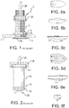
Fig. 1 is a sectional view illustrating the manner in which a penetrator member of the prior art is mounted in a boat hull opening; -
Fig. 2 is a side elevation view of a paddle-wheel-type velocity measuring device of the prior art that is used in connection with the penetrator member ofFig. 1 ; -
Fig. 3a is a sectional view of an embodiment of the invention, andFig. 3b is a bottom view of a modification of the apparatus ofFig. 3a ; -
Fig.4a is a sectional view of another embodiment of the invention, andFigs. 4b and 4c are bottom views of modifications of the apparatus ofFig. 4a ; -
Fig 5 is a sectional view of an electrode assembly utilizing a standard hull penetrator, wherein the magnet assembly is annular and is placed inside the boat concentrically about the hull penetrator: -
Fig 6 is a sectional view of an electrode assembly utilizing a standard hull penetrator, wherein the magnet assembly is solenoid-shaped and is concentrically arranged about the hull penetrator; -
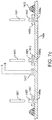
Figs. 7a - 7c are sectional views illustrating the locations of Hall Effect devices for monitoring the magnetic field strength for sensors having different electromagnetic devices, respectively; -
Figs. 8a - 8f are schematic illustrations of the preferred locations of the electromagnetic speedometer on various types of boats; -
Fig. 9 is a block diagram illustrating the combination of GPS signals with the forward speed and leeway signals, thereby to obtain direct measurement of the local currents that exist in the water; and -
Fig 10 is a circuit diagram illustrating the manner in which a magnetic field detecting device is connected with the electronic circuitry. - Referring first more particularly to
Fig. 1 , it is known in the prior art to provide a sensor for use in pleasure boats where a thru-hull mount already exists. A standard thru-hull penetrator 1 is typical of those used for impeller-type, electromagnetic, and ultrasonic speedometers. This penetrator includes a cylindrical body 2 having at one end aflange portion 2a and anannular rubber gasket 3 that reside on the water-side of theboat hull 4. An associatedhull locking nut 5 keeps the assembly in place in the hull through opening 4a. The body of the penetrator extends into the boat approximately 3 inches (approx. 7,6 cm). The penetrator body contains a smooth cylindrical cavity through which a standard sensor housing is inserted. -
Fig. 2 illustrates a typical prior art mechanical sensor, for example, asensor 20 of the type including apaddle wheel 22. Thepaddle wheel 22 protrudes approximately ½ inch (approx. 1,27 cm) beyond thehull 4 so it can be affected by the movement of the boat through the water. O-rings 24 arranged concentrically about the sensor body prevent water from entering the boat when either a sensor or a "dummy" sensor is in place.Lock nut 26 fastens thesensor 20 within the penetrator 2, and anouput cable 28 extends from the sensor. -
Figs. 3a and 3b show a first embodiment of the invention. The embodiment shown inFigs. 3a and 3b is designed to permit the user to remove and clean the electrodes while the boat is in the water, and underway. - The sensor means 300 in this embodiment includes a
shroud 308 formed of potting material and having the shape of an inverted mushroom, with themagnetic coil 304 andelectrode holes 306 of theguide tubes 307 being arranged adjacent the outer periphery of the shroud. Thestem portion 308a of the shroud extends within thestandard penetrator 302 mounted in hull opening 4a. The guide tubes are curved and includefirst portions 307a that extend downwardly through the shroud stem portion, andsecond portions 307b that extend radially outwardly in the mainshroud body portion 308b from the hull opening. Therefore, instead of the electrodes being securely potted into fixed locations on the periphery of the shroud, they extend through a plurality ofhollow guide tubes 307, thereby permitting the electrodes to be removed for cleaning. These electrodes are made of an electrically conductive, flexible material, such as stainless steel, or a composite graphite material. By incorporating in-lineminiature valves 312, the electrodes may be removed without leaving pathways for the outside water to enter the boat. Thesensor stem portion 308a andshroud 308 define an integral assembly, with theelectrode guide tubes 307,magnet coil 304, and mountingstem 308a being potted into a watertight assembly. - The shroud is flexible enough to generally conform to various boat hulls. To facilitate an even better conformance to the hull if the boat, an additional
annular gasket 313 is provided. To firmly secure the shroud and facilitate additional streamlining an attachment ring 318 (Fig. 3b ) may be provided that screws into thehull 4. Wires from the magnet coil are routed through the sensor stem and subsequently to the sensor electronics. - While the
valves 312 shown inFig 3a could be of the typical manually-operated type, such as miniature ball valves or gate valves, the preferred valves would be of the self-sealing elastomeric type, such as the small rubber "duckbill "valves or dome valves, similar to those manufactured by Vernay Laboratories, Inc. A dummy electrode assembly can be subsequently used to prevent inflow when the sensor is removed for extended periods of time. - While the previously described embodiment allows for the measurement of speed substantially outside of the ship's boundary layer, and allows for the removal and cleaning of the electrodes while the boat is in the water, the thickness of the shroud is increased by the magnetic coil remaining outside of the hull of the boat. Additionally, unlike the previous embodiment, if the coil were to fail during a critical sailing journey, the speedometer would remain inoperative until the boat could be removed from the water.
- In the embodiment of
Fig 4a , theshroud 408, mountingstem 409, and annularelectromagnetic coil 404 are all separate from each other. In particular, theannular coil 404 is located on the inside portion of thehull 4, away from the water where it could be serviced if necessary. In this embodiment, theshroud 406 contains only thehollow guide tubes 407 havingelectrode openings 406, so it can be much thinner than the previous embodiment wherein the shroud also contained the coil. Without having to accommodate the coil within the shroud, theshroud 408, provided with thegasket 413, can take a variety of shapes, including the disc-shapedconfiguration 408b ofFig. 4b provided with anattachment ring 419, and the four-armed cross shape 420 ofFig 4c . As in the prior configurations that incorporate hollow guide tubes for theremovable electrodes 414, thenecessary valves 412 for theguide tube portions 407a could be either of the manual inline type, or of the elastomeric self- sealing type. It should be noted that with thecoil 404 placed so it is separated from the water by the thickness of the hull, the strength of the magnetic field will be insignificantly slightly reduced. - In the embodiment of
Fig. 5 , the electrodes 1014 are contained withinguide tubes 1007 that extend through abody 1001 that is compatible with astandard hull penetrator 1002 and which allows for the electrodes to be removed without water intrusion. However, in this embodiment, theelectromagnetic coil 1010 is annular and is placed internally of thehull 1004 concentrically about thehull penetrator 1002. Such a configuration allows for a larger volume of water to be energized by the magnet than those configurations where the magnet is embedded within a structure that wholly fits inside of a standard penetrator. The magnetic field of this annual coil is spread over a wider volume but is limited in the depth of penetration into the water. Asensor body 1001 that fits inside astandard penetrator 1002 containsguide channels 1007 for respectively receiving a plurality of removable electrodes 1014. A plurality ofvalves 1012 are placed at the top of thesensor body 1001 such that each electrode must pass through the combination valve (or compression seal) prior to passing through a plurality ofguide channels 1007 before being installed at such a position so as to be in contact with the water at the outer portion of the boat hull. - In the embodiment of
Fig. 6 , theelectrodes 1111 are also contained withinpassages 1107 andpotting layer 1113 of asensor body 1100 that is compatible with astandard hull penetrator 1102 and which allows for the electrodes to be removed without water intrusion. Additionally themagnet assembly 1110 has a solenoid shape which will establish a magnetic field that extends deeper into the water than does the annular configuration. Such a configuration provides less sensitivity to disturbances at the hull than does the annular one. This solenoidelectromagnetic assembly 1110 is placed on the inside of thehull 1104 and is positioned concentrically about thehull penetrator 1102. Thus, the electromagnetic assembly can also be removed while the boat is in the water. Such a configuration allows for a larger volume of water to be energized by the magnet than those configurations where the magnet is embedded within a structure that wholly fits inside of a standard penetrator or, as inFig 5 , is of the annular shape. - The configurations of
Figs. 5 and 6 are designed for use with a standard hull penetrator. In these configurations, only one sensor body is used. The self-sealing valves are placed at the top of the assembly. The electrodes are grouped inside of a molded body that allow for the easy installation and removal. InFig. 5 the magnet is of annular shape and is large enough (approximately 2 inches, i.e. approx. 5 cm) to be placed around the hull penetrator on the inside of the hull. However, being relatively small and of the annular shape the depth of penetration is limited. InFig. 6 the magnet is of solenoid shape and is large enough (approximately 2 inches, i.e. approx. 5 cm) to be placed around the hull penetrator on the inside of the hull. Because this coil has a substantial length-to- diameter and a magnetic permeable core the magnetic field extends into the water further than any of the configurations that utilize the standard hull penetrator. The coil can be replaced without interfering with the water integrity of the boat. The configuration ofFig. 6 is the most accurate of any configurations that utilize the standard hull penetrator. -
Figs. 7a, 7b and7c illustrate the location of a Hall Effect device that can be used for monitoring the strength of the magnetic field. In many of the sensor configurations the relationship between the location of the electrode tips and the magnet is known and remains constant since they typically reside within the same structure. However, when the magnet and electrodes are separately removable then it is possible that the strength of the magnetic field that energizes the water may be affected if the magnet assembly were to be positioned differently than when the sensor was calibrated. Since the calibration of the sensor is directly proportional to the strength of the magnetic field, it is important to minimize any effects of such a repositioning of the magnet. InFig. 7a , theHall Effect device 1217 is located within the structure that holds theelectrode guide channels 1207. Ifannular coil 1210 were to be repositioned, then theHall Effect device 1217 would detect the change in field strength, and report this change to the processing electronics so that the calibration of the sensor would remain unchanged. InFig. 7b , theHall Effect device 1317 is located within the sensor body that holds theelectrode channels 1307. If solenoid shapedcoil 1310 were to be repositioned, then theHall Effect device 1317 would detect the change in field strength and report this change to the processing electronics so that the calibration of the sensor would remain unchanged. InFig 7c , theHall Effect sensor 1417 is placed near the center of the coil and directly against the inside hull of the boat. Ifannular coil 1410 were to be repositioned, then theHall Effect device 1417 would detect the change in field strength and report this change to the processing electronics, so that the calibration of the sensor would remain unchanged. -
Figs.8a - 8f illustrate the preferred locations for the electromagnetic speedometer for outboard and inboard runabout hulls, step hulls, sailboat hulls, inboard hulls, and fin keel sailboat hulls, respectively. -
Fig. 9 illustrates the manner in which the two-axis boat speedometer can be interfaced with an onboard global positioning system 1922 to yield the water currents that exist in the body of water being traversed by the boat. The electromagnetic sensor 1921 provides two outputs, namely, one output "a" representing the fore/aft velocity of the boat relative to the water, and the other output "b" representing the port/starboard velocity of the boat relative to the water. The onboard GPS system 1922 typically supplies two outputs, one output "c" representing the North/South velocity of the boat relative to land, and the other output "d" representing the East/West velocity of the boat relative to land. The two signals from the electromagnetic sensor and the two signals from the GPS are combined in computer 1923. By subtracting the speed of the ship through the water from the speed of the ship over land, the velocities of the North/South and East/West water current signals "e" and "f" relative to land can be calculated and supplied to indicating means 1624. -
Fig. 10 illustrates the manner in which the Hall effect device is connected with the electronic circuitry to maintain the proper calibration in the event that the strength of the magnetic field changes from that which existed during calibration. TheHall effect device 2060 is monitored bycomputer 2023. The strength of the magnetic field detected by theHall effect device 2060 is used to modify the velocity signals from theelectromagnetic sensor 2021 so as to maintain the system calibration if the strength of the magnetic field should change from the value recorded during a previous system calibration.
Claims (12)
- An electromagnetic speedometer suitable for use in a boat with a horizontal boat hull having a lower exterior surface exposed to the water, and an upper interior surface, and at least one through opening; the electromagnetic speedometer comprising:- a tubular penetrator member (302, 402, 1002, 1102, 1202, 1302), suitable to be mounted concentrically within said hull open ing;- a large diameter electromagnetic coil, suitable for being mounted on the hull for establishing an electromagnetic field in the water adjacent the hull lower surface and extending beyond a boundary layer within the water resulting from movement of the boat hull, the electromagnetic coil comprising a coil (304, 404 1010, 1110, 1210, 1310) mounted concentrically about said tubular penetrator member (302,402, 1002, 1102, 1202, 1302);- a plurality of electrodes (314, 414, 1011, 1111, 1211, 1311) having first ends provided with tips which engage with the water, said electrodes having second ends;- electrode support means containing guide passages (307, 407, 1007, 1107, 1207, 1307) removably supporting said electrodes within said tubular penetrator member (302, 402, 1002, 1102, 1202, 1302) to effect engagement of the electrode tips with the water adjacent said electromagnetic field and to permit removal of said electrodes and cleaning of said electrode tips when the boat is in the water, said electrode support means further including closure means comprising valves (312, 412, 1012, 1112, 1212, 1312) connected with said guide passages, respectively, and operable between a closed and an open position, said valves in said closed position preventing water from entering the boat hull when said electrodes are removed; and- velocity measuring circuit means arranged above said hull upper interior surface, said velocity measuring circuit means including a plurality of conductors respectively connected with said electrode second ends.
- An electromagnetic speedometer as defined in claim 1, wherein the tips of said electrodes are arranged in a predetermined pattern relative to the axis of travel of the boat; and further wherein said electromagnetic coil is connected with said hull in concentrically spaced relation about said electrode tips.
- An electromagnetic speedometer as defined in claim 2, and further including:- a synthetic plastic shroud member (308, 408) having a generally inverted- mushroom-shaped configuration including a horizontal body portion for being secured to said hull lower exterior surface, and a stem portion that extends upwardly through the tubular penetrator member (302, 402), said shroud member containing a plurality of guide passages (307,407) that extend downwardly through said shroud stem portion and radially outwardly toward electrode tip openings (306,406) contained in the bottom surface of said shroud member; (h) and further wherein said electrodes (314, 414) are flexible and removably extend in said guide passages downwardly through said shroud stem portion, and radially outwardly toward said electrode tip openings.
- An electromagnetic speedometer as defined in claim 3, wherein said electromagnetic coil is an annular coil (304) embedded in said shroud body portion.
- An electromagnetic speedometer as defined in claim 1,- said electrode support means comprising a sensor body (1001, 1100, 1880) mounted concentrically within said penetrator member, said electrodes extending through said sensor body .
- An electromagnetic speedometer as defined in claim 5, wherein said electromagnetic coil comprises a solenoid (1110, 1310) for mounting above said hull upper interior surface concentrically about an external surface of said penetrator member.
- An electromagnetic speedometer as defined in claim 5, wherein said electromagnetic coil comprises an annular coil {1010, 1210) mounted above said hull upper interior surface concentrically about an external surface of said penetrator member.
- An electromagnetic speedometer as defined in claim 5, wherein said sensor body is tubular, said electrodes extending through guide passages (1807) extending in circumferentially spaced relation longitudinally through said tubular sensor body.
- An electromagnetic speedometer as defined in claim 8, and further including at least one physical property measuring device (1883, 1884) mounted within said sensor body.
- An electromagnetic speedometer as defined in claim 1, and further including Hall effect sensing means (1217, 1317, 1883) arranged within said electromagnetic means adjacent said hull, said Hall effect means (1217, 1317, 1883) being connected with said velocity measuring circuit means.
- An electromagnetic speedometer as defined in claim 5,wherein said sensor body is removably mounted in said penetrator member.
- An electromagnetic speedometer as defined in claim 1, wherein said closure means include a plurality of dummy electrodes for insertion in said sensor body when said electrodes are removed.
Priority Applications (1)
| Application Number | Priority Date | Filing Date | Title |
|---|---|---|---|
| EP16192922.9A EP3139177B1 (en) | 2012-08-16 | 2013-07-31 | Improved electromagnetic boat speedometer having removable electrodes |
Applications Claiming Priority (3)
| Application Number | Priority Date | Filing Date | Title |
|---|---|---|---|
| US201213587876A | 2012-08-16 | 2012-08-16 | |
| US13/935,933 US9429588B2 (en) | 2012-08-16 | 2013-07-05 | Electromagnetic boat speedometer having removable electrodes |
| PCT/IB2013/002023 WO2014027244A2 (en) | 2012-08-16 | 2013-07-31 | Improved electromagnetic boat speedometer having removable electrodes |
Related Child Applications (2)
| Application Number | Title | Priority Date | Filing Date |
|---|---|---|---|
| EP16192922.9A Division EP3139177B1 (en) | 2012-08-16 | 2013-07-31 | Improved electromagnetic boat speedometer having removable electrodes |
| EP16192922.9A Division-Into EP3139177B1 (en) | 2012-08-16 | 2013-07-31 | Improved electromagnetic boat speedometer having removable electrodes |
Publications (3)
| Publication Number | Publication Date |
|---|---|
| EP2885644A2 EP2885644A2 (en) | 2015-06-24 |
| EP2885644A4 EP2885644A4 (en) | 2015-12-23 |
| EP2885644B1 true EP2885644B1 (en) | 2020-01-22 |
Family
ID=50099126
Family Applications (2)
| Application Number | Title | Priority Date | Filing Date |
|---|---|---|---|
| EP13829666.0A Active EP2885644B1 (en) | 2012-08-16 | 2013-07-31 | Improved electromagnetic boat speedometer having removable electrodes |
| EP16192922.9A Active EP3139177B1 (en) | 2012-08-16 | 2013-07-31 | Improved electromagnetic boat speedometer having removable electrodes |
Family Applications After (1)
| Application Number | Title | Priority Date | Filing Date |
|---|---|---|---|
| EP16192922.9A Active EP3139177B1 (en) | 2012-08-16 | 2013-07-31 | Improved electromagnetic boat speedometer having removable electrodes |
Country Status (5)
| Country | Link |
|---|---|
| US (2) | US9429588B2 (en) |
| EP (2) | EP2885644B1 (en) |
| ES (2) | ES2784860T3 (en) |
| NZ (1) | NZ703997A (en) |
| WO (1) | WO2014027244A2 (en) |
Families Citing this family (11)
| Publication number | Priority date | Publication date | Assignee | Title |
|---|---|---|---|---|
| US9983223B2 (en) | 2014-08-26 | 2018-05-29 | Brickhouse Innovations, Llc | Electromagnetic boat speedometer having boundary layer velocity compensation |
| CN105865546B (en) * | 2015-01-23 | 2022-03-15 | 北京斯威尔工业测量仪器有限公司 | Solid flow meter mounting structure |
| IT201800002751A1 (en) * | 2018-02-16 | 2019-08-16 | Eltek Spa | DETECTION AND / OR CONTROL DEVICE FOR LIQUID-CONDUCTED EQUIPMENT OR SYSTEMS |
| DE102018132600B4 (en) * | 2018-12-18 | 2024-02-22 | Endress+Hauser Flowtec Ag | Magnetic-inductive flow measuring probe and measuring point for determining a flow and/or an installation angle |
| DE102018132885B4 (en) * | 2018-12-19 | 2023-10-12 | Endress+Hauser Flowtec Ag | Magnetic-inductive flow measuring probe and measuring point |
| CN110058043A (en) * | 2019-04-12 | 2019-07-26 | 中国船舶重工集团公司第七0七研究所九江分部 | A kind of double electromagnet logs peculiar to vessel |
| CN112083184B (en) * | 2020-09-04 | 2022-10-21 | 中国船舶重工集团公司第七0七研究所九江分部 | Wing-like electromagnetic sensor with reverse series-connection double coils and glass fiber material |
| CN112362117A (en) * | 2020-10-30 | 2021-02-12 | 湖南达道新能源开发有限公司 | Heating power supply equipment convenient for mounting electromagnetic flowmeter |
| CN114675051B (en) * | 2022-03-08 | 2022-10-28 | 中国水利水电科学研究院 | River flow velocity monitoring device, system and method based on differential pressure measurement |
| CN115015575B (en) * | 2022-06-14 | 2023-03-28 | 浙江大学 | Autonomous energy supply type underwater flow velocity monitoring device capable of moving flexibly |
| CN116068221B (en) * | 2023-03-06 | 2023-06-06 | 中国空气动力研究与发展中心空天技术研究所 | Can waterproof airspeed measuring device |
Citations (1)
| Publication number | Priority date | Publication date | Assignee | Title |
|---|---|---|---|---|
| US6598487B1 (en) * | 2002-05-20 | 2003-07-29 | Marsh-Mcbirney, Inc. | Magnetic flowmeter having a separable magnet/electrode assembly |
Family Cites Families (61)
| Publication number | Priority date | Publication date | Assignee | Title |
|---|---|---|---|---|
| US3119960A (en) | 1960-05-10 | 1964-01-28 | David E Kenyon | Electromagnetic marine speedometer mounted substantially flush with an outer surface of a ship |
| US3161047A (en) * | 1960-05-27 | 1964-12-15 | Griswold Lyman William | Omnidirectional electromagnetic flowmeter |
| US3354714A (en) | 1964-12-01 | 1967-11-28 | Raytheon Co | Marine speedometer |
| US3372589A (en) | 1965-06-14 | 1968-03-12 | Fischer & Porter Co | Side-saddle magnetic flowmeter |
| US3380299A (en) | 1966-04-04 | 1968-04-30 | Prototypes Inc | Boat speedometer |
| FR95028E (en) * | 1967-04-27 | 1970-03-27 | Ben Soc | Advanced training in current meters and electromagnetic logs. |
| US3400582A (en) | 1967-05-08 | 1968-09-10 | Eric S. Warner | Boat speed indicator |
| US3482444A (en) | 1967-11-02 | 1969-12-09 | Stewart Warner Corp | Electrical boat-speedometer apparatus |
| US3496770A (en) | 1968-01-10 | 1970-02-24 | James M Fassett | Boat velocity indicating arrangement |
| US3531988A (en) | 1969-02-19 | 1970-10-06 | Transdynamics Inc | Knotmeter |
| USRE28839E (en) | 1971-02-03 | 1976-06-08 | Marine speedometer | |
| US3813938A (en) * | 1971-12-23 | 1974-06-04 | Fischer & Porter Co | Electrode holder for electromagnetic flowmeters |
| US3800592A (en) | 1972-01-13 | 1974-04-02 | Westerbeke J Corp | Flowmeter |
| US3777561A (en) * | 1972-02-03 | 1973-12-11 | Harnessed En Inc | Faraday effect speedometer |
| US3930413A (en) | 1972-12-07 | 1976-01-06 | Caterpillar Tractor Co. | Quick release gauge fitting |
| US3940983A (en) | 1975-03-19 | 1976-03-02 | Safe Flight Instrument Corporation | Faraday effect fluid flow and direction indicator |
| US4079626A (en) | 1976-07-06 | 1978-03-21 | Gardner William L | Electromagnetic flow meter |
| US4125019A (en) | 1977-06-16 | 1978-11-14 | Monitek, Inc. | Probe type electromagnetic flow meter with debris shedding capability |
| US4297897A (en) * | 1979-08-09 | 1981-11-03 | Emerson Electric Co. | Field replaceable electrode assembly for magnetic flowmeter |
| US4261210A (en) * | 1979-10-09 | 1981-04-14 | Gardner William L | Stacked wafer helical flowmeter |
| US4308753A (en) * | 1979-12-03 | 1982-01-05 | The United States Of America As Represented By The Secretary Of The Navy | Low-power electromagnetic flowmeter |
| DE3018260A1 (en) * | 1980-05-13 | 1981-11-19 | Turbo-Werk Fritz Hammelrath, 5000 Köln | Drainage measurement of open channels - has level and inductive flow speed measurement devices with signal multiplier circuit |
| US4346604A (en) * | 1980-07-14 | 1982-08-31 | Narco Bio-Systems, Inc. | Electromagnetic flow probe |
| US4389898A (en) | 1980-12-04 | 1983-06-28 | Long James C | Electromagnetic velocity transducer |
| US4459858A (en) | 1981-09-18 | 1984-07-17 | Marsh-Mcbirney, Inc. | Flow meter having an electromagnetic sensor probe |
| US4424833A (en) * | 1981-10-02 | 1984-01-10 | C. R. Bard, Inc. | Self sealing gasket assembly |
| DE3236909A1 (en) | 1982-10-06 | 1984-04-12 | Turbo-Werk Messtechnik GmbH, 5000 Köln | MEASURING DEVICE FOR INDUCTIVE MEASUREMENT OF THE FLOW SPEED OF LIQUID MEDIA |
| AU4599285A (en) | 1984-08-15 | 1986-02-20 | Development Finance Corporation Of New Zealand, The | Faraday effect marine speed transducer |
| US4549434A (en) | 1984-10-26 | 1985-10-29 | Marsh-Mcbirney, Inc. | Pressure level sensor |
| US4688432A (en) | 1986-02-27 | 1987-08-25 | Marsh Lawrence B | Averaging velocity sensor for measuring fluid flow in a conduit |
| USRE33982E (en) | 1987-01-28 | 1992-07-07 | Airmar Technology Corporation | Marine instrument |
| US4848146A (en) * | 1988-07-21 | 1989-07-18 | Bruno Anthony B | Underwater electromagnetic tubulent velocimeter |
| US5110310A (en) | 1991-04-25 | 1992-05-05 | Lakeland Engineering Corporation | Automatic speed control system for boats |
| US5186050A (en) | 1991-09-25 | 1993-02-16 | Airmar Technology Corporation | Marine sensor mounting mechanism |
| US5313842A (en) | 1992-01-02 | 1994-05-24 | Marsh-Mcbirnes, Inc. | Pump station flowmeter with sudden high inflow change detector |
| US5263374A (en) | 1992-01-24 | 1993-11-23 | Marsh-Mcbirney, Inc. | Flowmeter with concentrically arranged electromagnetic field |
| US5398552A (en) | 1993-10-26 | 1995-03-21 | Marsh-Mcbirney, Inc. | Magnetic flowmeter having a separable magnetic assembly |
| GB2292613A (en) * | 1994-08-01 | 1996-02-28 | Edward Hall Higham | Multiple electrode electromagnetic flowmeters |
| US5583289A (en) | 1994-08-19 | 1996-12-10 | Airguide Instrument Company | Marine velocity detection device with channel to wash out debris |
| US5421211A (en) | 1994-10-06 | 1995-06-06 | Marsh - Mcbirney, Inc. | Liquid flowmeter including doppler signal processing, and method |
| US5838635A (en) * | 1994-11-14 | 1998-11-17 | Masreliez; Karl | Thin speed transducer sensor |
| US5544531A (en) | 1995-01-09 | 1996-08-13 | Marsh-Mcbirney, Inc. | Flowmeter having active temperature compensation |
| US5644088A (en) | 1995-07-27 | 1997-07-01 | Marsh-Mcbirney, Inc. | Port forward sensor for liquid level gauge or flowmeter |
| US5684250A (en) | 1995-08-21 | 1997-11-04 | Marsh-Mcbirney, Inc. | Self-calibrating open-channel flowmeter |
| US5594179A (en) | 1995-11-06 | 1997-01-14 | Marsh-Mcbirney, Inc. | Tracer type flowmeter and method using two or more injected trace materials |
| US5811688A (en) | 1996-01-18 | 1998-09-22 | Marsh-Mcbirney, Inc. | Open channel flowmeter utilizing surface velocity and lookdown level devices |
| US5581025A (en) | 1996-02-12 | 1996-12-03 | Airmar Technology Corp. | Marine instrument |
| GB9608788D0 (en) * | 1996-04-27 | 1996-07-03 | Kodak Ltd | Improvements in or relating to flow meters |
| US5866823A (en) * | 1997-05-13 | 1999-02-02 | Hersey Measurement Company | Commutating electrode magnetic flowmeter |
| DE19950751A1 (en) | 1999-10-21 | 2001-04-26 | Hans Joachim Bamert | Holding unit for ship log data transmitter comprises head on dry end of sleeve with two-way shutoff slide to close off free center holes through head and sleeve. |
| AU2003235684A1 (en) | 2002-01-10 | 2003-07-30 | Svm Machining, Inc. | Tool for cleaning a watercraft speedometer |
| US6904798B2 (en) | 2002-08-08 | 2005-06-14 | Airmar Technology Corporation | Multi-functional marine sensing instrument |
| US7877174B2 (en) | 2005-02-11 | 2011-01-25 | Econtrols, Inc. | Watercraft speed control device |
| US7073393B2 (en) * | 2004-11-01 | 2006-07-11 | Rosemount Inc. | Magnetic flowmeter with built-in simulator |
| US7613072B2 (en) | 2005-06-29 | 2009-11-03 | Nortek, AS | System and method for determining directional and non-directional fluid wave and current measurements |
| US7352651B2 (en) | 2005-06-29 | 2008-04-01 | Nortek As | System and method for determining directional and non-directional fluid wave and current measurements |
| GB2434374A (en) | 2006-01-20 | 2007-07-25 | Malcolm John Perrins | Immersed electrode |
| US7911880B2 (en) | 2007-05-22 | 2011-03-22 | Nortek As | Acoustic doppler dual current profiler system and method |
| US8136410B2 (en) * | 2010-01-06 | 2012-03-20 | Mccrometer, Inc. | Sensor assembly for a fluid flowmeter |
| US8434371B2 (en) * | 2010-10-14 | 2013-05-07 | Brickhouse Innovations, Llc | Electromagnetic fluid velocity sensor with adjustable electrodes |
| US9116060B2 (en) | 2012-05-23 | 2015-08-25 | Hach Company | Auto-zeroing absolute pressure sensor |
-
2013
- 2013-07-05 US US13/935,933 patent/US9429588B2/en active Active
- 2013-07-31 WO PCT/IB2013/002023 patent/WO2014027244A2/en active Application Filing
- 2013-07-31 EP EP13829666.0A patent/EP2885644B1/en active Active
- 2013-07-31 ES ES13829666T patent/ES2784860T3/en active Active
- 2013-07-31 ES ES16192922T patent/ES2729661T3/en active Active
- 2013-07-31 EP EP16192922.9A patent/EP3139177B1/en active Active
- 2013-07-31 NZ NZ703997A patent/NZ703997A/en unknown
-
2016
- 2016-07-29 US US15/223,755 patent/US10416187B2/en active Active
Patent Citations (1)
| Publication number | Priority date | Publication date | Assignee | Title |
|---|---|---|---|---|
| US6598487B1 (en) * | 2002-05-20 | 2003-07-29 | Marsh-Mcbirney, Inc. | Magnetic flowmeter having a separable magnet/electrode assembly |
Also Published As
| Publication number | Publication date |
|---|---|
| NZ703997A (en) | 2017-09-29 |
| ES2784860T3 (en) | 2020-10-01 |
| EP3139177B1 (en) | 2019-03-06 |
| US9429588B2 (en) | 2016-08-30 |
| EP3139177A1 (en) | 2017-03-08 |
| US20140047927A1 (en) | 2014-02-20 |
| ES2729661T3 (en) | 2019-11-05 |
| WO2014027244A2 (en) | 2014-02-20 |
| EP2885644A2 (en) | 2015-06-24 |
| WO2014027244A3 (en) | 2014-05-22 |
| EP2885644A4 (en) | 2015-12-23 |
| WO2014027244A4 (en) | 2014-07-10 |
| US20160377646A1 (en) | 2016-12-29 |
| US10416187B2 (en) | 2019-09-17 |
Similar Documents
| Publication | Publication Date | Title |
|---|---|---|
| EP2885644B1 (en) | Improved electromagnetic boat speedometer having removable electrodes | |
| KR101674373B1 (en) | Sensor for monitoring corrosion and method for manufacturinf same | |
| RU2011140864A (en) | MARINE SEISMIC EXPLORATION IN ICE-COATED OR HAVING OBSTACLES OF WATERS | |
| KR102122983B1 (en) | Sensor assembly for measuring a current for an underwater vehicle | |
| CN109827551B (en) | Split type ocean boundary layer observation equipment and method | |
| Meurer et al. | Differential pressure sensor speedometer for autonomous underwater vehicle velocity estimation | |
| Kume et al. | Measurements of hydrodynamic forces, surface pressure, and wake for obliquely towed tanker model and uncertainty analysis for CFD validation | |
| JP2019532262A (en) | Method and system for optimizing ship operations | |
| CN111386467A (en) | Ship water velocity measuring device calibration method using numerical analysis | |
| EP3186643B1 (en) | Electromagnetic boat speedometer including boundary layer velocity compensation | |
| US8381584B1 (en) | Model hull testing method, platform, and system | |
| CN113135276A (en) | Depth finder transducer mounting structure and mounting method thereof | |
| JP2002145187A (en) | Submarine boat and distribution measuring method | |
| KR100976615B1 (en) | Water quality measurement buoy device | |
| CN107660302B (en) | Ship body assembling electronic equipment for ship | |
| US6308581B1 (en) | Differential pressure flow sensor | |
| US8375782B1 (en) | Model hull testing method, platform, and system | |
| US5578751A (en) | Oceanographic sensor suite wet well system | |
| CN107176266A (en) | A kind of marine locator installs equipment | |
| US20080293314A1 (en) | Trolling motor cable cover | |
| EP0114089A2 (en) | Measuring the draft of a vessel | |
| US20200088755A1 (en) | Watercraft speed sensor | |
| CN104118540A (en) | Real-ship measurement method for navigation squat of inland ship | |
| KR101489867B1 (en) | The boat support apparatus for echo sounder ultrasonic sensor protective | |
| CN219237309U (en) | Floating type ship tail dragging device of shallow stratum profiler |
Legal Events
| Date | Code | Title | Description |
|---|---|---|---|
| PUAI | Public reference made under article 153(3) epc to a published international application that has entered the european phase |
Free format text: ORIGINAL CODE: 0009012 |
|
| 17P | Request for examination filed |
Effective date: 20150211 |
|
| AK | Designated contracting states |
Kind code of ref document: A2 Designated state(s): AL AT BE BG CH CY CZ DE DK EE ES FI FR GB GR HR HU IE IS IT LI LT LU LV MC MK MT NL NO PL PT RO RS SE SI SK SM TR |
|
| AX | Request for extension of the european patent |
Extension state: BA ME |
|
| DAX | Request for extension of the european patent (deleted) | ||
| A4 | Supplementary search report drawn up and despatched |
Effective date: 20151125 |
|
| RIC1 | Information provided on ipc code assigned before grant |
Ipc: G01P 5/08 20060101ALI20151119BHEP Ipc: G01F 1/58 20060101AFI20151119BHEP |
|
| STAA | Information on the status of an ep patent application or granted ep patent |
Free format text: STATUS: EXAMINATION IS IN PROGRESS |
|
| 17Q | First examination report despatched |
Effective date: 20170207 |
|
| GRAP | Despatch of communication of intention to grant a patent |
Free format text: ORIGINAL CODE: EPIDOSNIGR1 |
|
| STAA | Information on the status of an ep patent application or granted ep patent |
Free format text: STATUS: GRANT OF PATENT IS INTENDED |
|
| INTG | Intention to grant announced |
Effective date: 20190903 |
|
| GRAS | Grant fee paid |
Free format text: ORIGINAL CODE: EPIDOSNIGR3 |
|
| GRAA | (expected) grant |
Free format text: ORIGINAL CODE: 0009210 |
|
| STAA | Information on the status of an ep patent application or granted ep patent |
Free format text: STATUS: THE PATENT HAS BEEN GRANTED |
|
| AK | Designated contracting states |
Kind code of ref document: B1 Designated state(s): AL AT BE BG CH CY CZ DE DK EE ES FI FR GB GR HR HU IE IS IT LI LT LU LV MC MK MT NL NO PL PT RO RS SE SI SK SM TR |
|
| REG | Reference to a national code |
Ref country code: GB Ref legal event code: FG4D |
|
| REG | Reference to a national code |
Ref country code: CH Ref legal event code: EP |
|
| REG | Reference to a national code |
Ref country code: DE Ref legal event code: R096 Ref document number: 602013065353 Country of ref document: DE |
|
| REG | Reference to a national code |
Ref country code: AT Ref legal event code: REF Ref document number: 1227196 Country of ref document: AT Kind code of ref document: T Effective date: 20200215 |
|
| REG | Reference to a national code |
Ref country code: IE Ref legal event code: FG4D |
|
| REG | Reference to a national code |
Ref country code: NO Ref legal event code: T2 Effective date: 20200122 |
|
| REG | Reference to a national code |
Ref country code: NL Ref legal event code: MP Effective date: 20200122 |
|
| REG | Reference to a national code |
Ref country code: LT Ref legal event code: MG4D |
|
| PG25 | Lapsed in a contracting state [announced via postgrant information from national office to epo] |
Ref country code: FI Free format text: LAPSE BECAUSE OF FAILURE TO SUBMIT A TRANSLATION OF THE DESCRIPTION OR TO PAY THE FEE WITHIN THE PRESCRIBED TIME-LIMIT Effective date: 20200122 Ref country code: RS Free format text: LAPSE BECAUSE OF FAILURE TO SUBMIT A TRANSLATION OF THE DESCRIPTION OR TO PAY THE FEE WITHIN THE PRESCRIBED TIME-LIMIT Effective date: 20200122 Ref country code: NL Free format text: LAPSE BECAUSE OF FAILURE TO SUBMIT A TRANSLATION OF THE DESCRIPTION OR TO PAY THE FEE WITHIN THE PRESCRIBED TIME-LIMIT Effective date: 20200122 Ref country code: PT Free format text: LAPSE BECAUSE OF FAILURE TO SUBMIT A TRANSLATION OF THE DESCRIPTION OR TO PAY THE FEE WITHIN THE PRESCRIBED TIME-LIMIT Effective date: 20200614 |
|
| PG25 | Lapsed in a contracting state [announced via postgrant information from national office to epo] |
Ref country code: SE Free format text: LAPSE BECAUSE OF FAILURE TO SUBMIT A TRANSLATION OF THE DESCRIPTION OR TO PAY THE FEE WITHIN THE PRESCRIBED TIME-LIMIT Effective date: 20200122 Ref country code: IS Free format text: LAPSE BECAUSE OF FAILURE TO SUBMIT A TRANSLATION OF THE DESCRIPTION OR TO PAY THE FEE WITHIN THE PRESCRIBED TIME-LIMIT Effective date: 20200522 Ref country code: LV Free format text: LAPSE BECAUSE OF FAILURE TO SUBMIT A TRANSLATION OF THE DESCRIPTION OR TO PAY THE FEE WITHIN THE PRESCRIBED TIME-LIMIT Effective date: 20200122 Ref country code: HR Free format text: LAPSE BECAUSE OF FAILURE TO SUBMIT A TRANSLATION OF THE DESCRIPTION OR TO PAY THE FEE WITHIN THE PRESCRIBED TIME-LIMIT Effective date: 20200122 Ref country code: GR Free format text: LAPSE BECAUSE OF FAILURE TO SUBMIT A TRANSLATION OF THE DESCRIPTION OR TO PAY THE FEE WITHIN THE PRESCRIBED TIME-LIMIT Effective date: 20200423 Ref country code: BG Free format text: LAPSE BECAUSE OF FAILURE TO SUBMIT A TRANSLATION OF THE DESCRIPTION OR TO PAY THE FEE WITHIN THE PRESCRIBED TIME-LIMIT Effective date: 20200422 |
|
| REG | Reference to a national code |
Ref country code: ES Ref legal event code: FG2A Ref document number: 2784860 Country of ref document: ES Kind code of ref document: T3 Effective date: 20201001 |
|
| REG | Reference to a national code |
Ref country code: DE Ref legal event code: R097 Ref document number: 602013065353 Country of ref document: DE |
|
| PG25 | Lapsed in a contracting state [announced via postgrant information from national office to epo] |
Ref country code: EE Free format text: LAPSE BECAUSE OF FAILURE TO SUBMIT A TRANSLATION OF THE DESCRIPTION OR TO PAY THE FEE WITHIN THE PRESCRIBED TIME-LIMIT Effective date: 20200122 Ref country code: LT Free format text: LAPSE BECAUSE OF FAILURE TO SUBMIT A TRANSLATION OF THE DESCRIPTION OR TO PAY THE FEE WITHIN THE PRESCRIBED TIME-LIMIT Effective date: 20200122 Ref country code: SM Free format text: LAPSE BECAUSE OF FAILURE TO SUBMIT A TRANSLATION OF THE DESCRIPTION OR TO PAY THE FEE WITHIN THE PRESCRIBED TIME-LIMIT Effective date: 20200122 Ref country code: RO Free format text: LAPSE BECAUSE OF FAILURE TO SUBMIT A TRANSLATION OF THE DESCRIPTION OR TO PAY THE FEE WITHIN THE PRESCRIBED TIME-LIMIT Effective date: 20200122 Ref country code: CZ Free format text: LAPSE BECAUSE OF FAILURE TO SUBMIT A TRANSLATION OF THE DESCRIPTION OR TO PAY THE FEE WITHIN THE PRESCRIBED TIME-LIMIT Effective date: 20200122 Ref country code: SK Free format text: LAPSE BECAUSE OF FAILURE TO SUBMIT A TRANSLATION OF THE DESCRIPTION OR TO PAY THE FEE WITHIN THE PRESCRIBED TIME-LIMIT Effective date: 20200122 Ref country code: DK Free format text: LAPSE BECAUSE OF FAILURE TO SUBMIT A TRANSLATION OF THE DESCRIPTION OR TO PAY THE FEE WITHIN THE PRESCRIBED TIME-LIMIT Effective date: 20200122 |
|
| REG | Reference to a national code |
Ref country code: AT Ref legal event code: MK05 Ref document number: 1227196 Country of ref document: AT Kind code of ref document: T Effective date: 20200122 |
|
| PLBE | No opposition filed within time limit |
Free format text: ORIGINAL CODE: 0009261 |
|
| STAA | Information on the status of an ep patent application or granted ep patent |
Free format text: STATUS: NO OPPOSITION FILED WITHIN TIME LIMIT |
|
| 26N | No opposition filed |
Effective date: 20201023 |
|
| PG25 | Lapsed in a contracting state [announced via postgrant information from national office to epo] |
Ref country code: AT Free format text: LAPSE BECAUSE OF FAILURE TO SUBMIT A TRANSLATION OF THE DESCRIPTION OR TO PAY THE FEE WITHIN THE PRESCRIBED TIME-LIMIT Effective date: 20200122 Ref country code: IT Free format text: LAPSE BECAUSE OF FAILURE TO SUBMIT A TRANSLATION OF THE DESCRIPTION OR TO PAY THE FEE WITHIN THE PRESCRIBED TIME-LIMIT Effective date: 20200122 |
|
| PG25 | Lapsed in a contracting state [announced via postgrant information from national office to epo] |
Ref country code: SI Free format text: LAPSE BECAUSE OF FAILURE TO SUBMIT A TRANSLATION OF THE DESCRIPTION OR TO PAY THE FEE WITHIN THE PRESCRIBED TIME-LIMIT Effective date: 20200122 Ref country code: PL Free format text: LAPSE BECAUSE OF FAILURE TO SUBMIT A TRANSLATION OF THE DESCRIPTION OR TO PAY THE FEE WITHIN THE PRESCRIBED TIME-LIMIT Effective date: 20200122 Ref country code: MC Free format text: LAPSE BECAUSE OF FAILURE TO SUBMIT A TRANSLATION OF THE DESCRIPTION OR TO PAY THE FEE WITHIN THE PRESCRIBED TIME-LIMIT Effective date: 20200122 |
|
| REG | Reference to a national code |
Ref country code: CH Ref legal event code: PL |
|
| REG | Reference to a national code |
Ref country code: BE Ref legal event code: MM Effective date: 20200731 |
|
| PG25 | Lapsed in a contracting state [announced via postgrant information from national office to epo] |
Ref country code: LU Free format text: LAPSE BECAUSE OF NON-PAYMENT OF DUE FEES Effective date: 20200731 Ref country code: CH Free format text: LAPSE BECAUSE OF NON-PAYMENT OF DUE FEES Effective date: 20200731 Ref country code: LI Free format text: LAPSE BECAUSE OF NON-PAYMENT OF DUE FEES Effective date: 20200731 |
|
| PG25 | Lapsed in a contracting state [announced via postgrant information from national office to epo] |
Ref country code: BE Free format text: LAPSE BECAUSE OF NON-PAYMENT OF DUE FEES Effective date: 20200731 |
|
| PG25 | Lapsed in a contracting state [announced via postgrant information from national office to epo] |
Ref country code: IE Free format text: LAPSE BECAUSE OF NON-PAYMENT OF DUE FEES Effective date: 20200731 |
|
| PG25 | Lapsed in a contracting state [announced via postgrant information from national office to epo] |
Ref country code: TR Free format text: LAPSE BECAUSE OF FAILURE TO SUBMIT A TRANSLATION OF THE DESCRIPTION OR TO PAY THE FEE WITHIN THE PRESCRIBED TIME-LIMIT Effective date: 20200122 Ref country code: MT Free format text: LAPSE BECAUSE OF FAILURE TO SUBMIT A TRANSLATION OF THE DESCRIPTION OR TO PAY THE FEE WITHIN THE PRESCRIBED TIME-LIMIT Effective date: 20200122 Ref country code: CY Free format text: LAPSE BECAUSE OF FAILURE TO SUBMIT A TRANSLATION OF THE DESCRIPTION OR TO PAY THE FEE WITHIN THE PRESCRIBED TIME-LIMIT Effective date: 20200122 |
|
| PG25 | Lapsed in a contracting state [announced via postgrant information from national office to epo] |
Ref country code: MK Free format text: LAPSE BECAUSE OF FAILURE TO SUBMIT A TRANSLATION OF THE DESCRIPTION OR TO PAY THE FEE WITHIN THE PRESCRIBED TIME-LIMIT Effective date: 20200122 Ref country code: AL Free format text: LAPSE BECAUSE OF FAILURE TO SUBMIT A TRANSLATION OF THE DESCRIPTION OR TO PAY THE FEE WITHIN THE PRESCRIBED TIME-LIMIT Effective date: 20200122 |
|
| PGFP | Annual fee paid to national office [announced via postgrant information from national office to epo] |
Ref country code: NO Payment date: 20230720 Year of fee payment: 11 Ref country code: GB Payment date: 20230713 Year of fee payment: 11 Ref country code: ES Payment date: 20230811 Year of fee payment: 11 |
|
| PGFP | Annual fee paid to national office [announced via postgrant information from national office to epo] |
Ref country code: FR Payment date: 20230724 Year of fee payment: 11 Ref country code: DE Payment date: 20230713 Year of fee payment: 11 |