EP2885205B1 - Ensemble porte pour l'intérieur d'un avion - Google Patents
Ensemble porte pour l'intérieur d'un avion Download PDFInfo
- Publication number
- EP2885205B1 EP2885205B1 EP12767094.1A EP12767094A EP2885205B1 EP 2885205 B1 EP2885205 B1 EP 2885205B1 EP 12767094 A EP12767094 A EP 12767094A EP 2885205 B1 EP2885205 B1 EP 2885205B1
- Authority
- EP
- European Patent Office
- Prior art keywords
- pressure
- door
- relief element
- carriage
- footer
- Prior art date
- Legal status (The legal status is an assumption and is not a legal conclusion. Google has not performed a legal analysis and makes no representation as to the accuracy of the status listed.)
- Not-in-force
Links
- 230000005291 magnetic effect Effects 0.000 claims description 20
- 230000000717 retained effect Effects 0.000 claims description 7
- 230000006837 decompression Effects 0.000 description 13
- 238000000429 assembly Methods 0.000 description 11
- 230000000712 assembly Effects 0.000 description 11
- 230000007246 mechanism Effects 0.000 description 9
- 238000010168 coupling process Methods 0.000 description 8
- 238000005859 coupling reaction Methods 0.000 description 8
- 230000006378 damage Effects 0.000 description 7
- 230000008878 coupling Effects 0.000 description 5
- 230000001066 destructive effect Effects 0.000 description 4
- 208000027418 Wounds and injury Diseases 0.000 description 3
- 230000004888 barrier function Effects 0.000 description 3
- 208000014674 injury Diseases 0.000 description 3
- 238000003780 insertion Methods 0.000 description 3
- 230000037431 insertion Effects 0.000 description 3
- 238000005299 abrasion Methods 0.000 description 2
- 230000003993 interaction Effects 0.000 description 2
- 239000000696 magnetic material Substances 0.000 description 2
- 230000014759 maintenance of location Effects 0.000 description 2
- 238000000034 method Methods 0.000 description 2
- 238000012986 modification Methods 0.000 description 2
- 230000004048 modification Effects 0.000 description 2
- 230000009467 reduction Effects 0.000 description 2
- 230000001360 synchronised effect Effects 0.000 description 2
- 240000005319 Sedum acre Species 0.000 description 1
- 229910000831 Steel Inorganic materials 0.000 description 1
- 238000013459 approach Methods 0.000 description 1
- 238000007664 blowing Methods 0.000 description 1
- 230000000295 complement effect Effects 0.000 description 1
- 230000003247 decreasing effect Effects 0.000 description 1
- 238000004880 explosion Methods 0.000 description 1
- 239000003302 ferromagnetic material Substances 0.000 description 1
- 238000009434 installation Methods 0.000 description 1
- 239000000463 material Substances 0.000 description 1
- 238000005192 partition Methods 0.000 description 1
- 230000008439 repair process Effects 0.000 description 1
- 238000012552 review Methods 0.000 description 1
- 238000005096 rolling process Methods 0.000 description 1
- 239000010959 steel Substances 0.000 description 1
- 238000013022 venting Methods 0.000 description 1
Images


Classifications
-
- B—PERFORMING OPERATIONS; TRANSPORTING
- B64—AIRCRAFT; AVIATION; COSMONAUTICS
- B64C—AEROPLANES; HELICOPTERS
- B64C1/00—Fuselages; Constructional features common to fuselages, wings, stabilising surfaces or the like
- B64C1/14—Windows; Doors; Hatch covers or access panels; Surrounding frame structures; Canopies; Windscreens accessories therefor, e.g. pressure sensors, water deflectors, hinges, seals, handles, latches, windscreen wipers
- B64C1/1407—Doors; surrounding frames
- B64C1/1423—Passenger doors
- B64C1/1438—Passenger doors of the sliding type
-
- B—PERFORMING OPERATIONS; TRANSPORTING
- B64—AIRCRAFT; AVIATION; COSMONAUTICS
- B64C—AEROPLANES; HELICOPTERS
- B64C1/00—Fuselages; Constructional features common to fuselages, wings, stabilising surfaces or the like
- B64C1/14—Windows; Doors; Hatch covers or access panels; Surrounding frame structures; Canopies; Windscreens accessories therefor, e.g. pressure sensors, water deflectors, hinges, seals, handles, latches, windscreen wipers
- B64C1/1407—Doors; surrounding frames
- B64C1/1469—Doors between cockpit and cabin
-
- B—PERFORMING OPERATIONS; TRANSPORTING
- B64—AIRCRAFT; AVIATION; COSMONAUTICS
- B64D—EQUIPMENT FOR FITTING IN OR TO AIRCRAFT; FLIGHT SUITS; PARACHUTES; ARRANGEMENT OR MOUNTING OF POWER PLANTS OR PROPULSION TRANSMISSIONS IN AIRCRAFT
- B64D25/00—Emergency apparatus or devices, not otherwise provided for
-
- E—FIXED CONSTRUCTIONS
- E06—DOORS, WINDOWS, SHUTTERS, OR ROLLER BLINDS IN GENERAL; LADDERS
- E06B—FIXED OR MOVABLE CLOSURES FOR OPENINGS IN BUILDINGS, VEHICLES, FENCES OR LIKE ENCLOSURES IN GENERAL, e.g. DOORS, WINDOWS, BLINDS, GATES
- E06B7/00—Special arrangements or measures in connection with doors or windows
- E06B7/16—Sealing arrangements on wings or parts co-operating with the wings
-
- E—FIXED CONSTRUCTIONS
- E06—DOORS, WINDOWS, SHUTTERS, OR ROLLER BLINDS IN GENERAL; LADDERS
- E06B—FIXED OR MOVABLE CLOSURES FOR OPENINGS IN BUILDINGS, VEHICLES, FENCES OR LIKE ENCLOSURES IN GENERAL, e.g. DOORS, WINDOWS, BLINDS, GATES
- E06B7/00—Special arrangements or measures in connection with doors or windows
- E06B7/28—Other arrangements on doors or windows, e.g. door-plates, windows adapted to carry plants, hooks for window cleaners
-
- B—PERFORMING OPERATIONS; TRANSPORTING
- B64—AIRCRAFT; AVIATION; COSMONAUTICS
- B64C—AEROPLANES; HELICOPTERS
- B64C1/00—Fuselages; Constructional features common to fuselages, wings, stabilising surfaces or the like
- B64C2001/009—Fuselages; Constructional features common to fuselages, wings, stabilising surfaces or the like comprising decompression panels or valves for pressure equalisation in fuselages or floors
Definitions
- the disclosure relates generally to doors for use in aircraft interiors, and more particularly, to the pressure-relief functionality of such doors and to the reduction of light bleed across such doors.
- Aircraft interiors are often designed to fit the needs of individual buyers.
- Such aircraft interiors can comprise doors for opening or closing passages between zones of the aircraft interior. It is often preferred to use doors which slide into pockets (i.e. pocket doors) in a bulkhead because such doors can be more aesthetically pleasing.
- a pocket door can comprise one or two segments which slide(s) horizontally in a sliding plane perpendicular to the floor of the aircraft interior and move(s) laterally to open or close the passages between the zones within the aircraft interior. When the pocket door is in an open position, the door segment(s) is/are recessed into the bulkhead pockets and occupants can pass through the passage.
- Aircraft certification authorities require that doors of an aircraft interior have blow-out functionality during rapid decompression events. For example, if there is rapid decompression in one of the two adjacent zones of the aircraft interior during flight, the aircraft door must be capable of blowing out to relieve the pressure differential between the adjacent zones without shattering. This concern might be particularly prevalent when the air circulation between the adjacent zones is limited such as, for example, when the aircraft door is in a closed position.
- blow-out functionality is to avoid damage to other parts of the aircraft interior, such as bulkheads separating the adjacent zones, and also avoid injury to aircraft occupants by flying debris.
- blow-out panels Aircraft interior doors with blow-out panels are known and are used between different zones within aircraft interiors.
- Known blow-out panels are designed to blow-out (e.g. become released) in the presence of a predetermined pressure differential to create an opening between the adjacent zones and rapidly equalize the pressure differential between the two zones.
- Some known blow-out panels are retained in position by frangible structure designed to break in the event of a predetermined pressure differential to allow for the pressure-relief function of the panel. Consequently, such frangible support structure can be relatively weak and can sometimes fail prematurely during normal use.
- U.S. Patent No. 6,866,226 discloses a panel within a door where the panel is allowed to become disengaged during a decompression event instead of having the door and/or panel structure structurally fail.
- Pratt discloses a latching mechanism used to hold the panel in position during normal use and a pressure-responsive device coupled to the latching mechanism. The pressure responsive device is operable to respond to a pressure differential across the panel to allow the latching mechanism to become unlatched during a decompression event to thereby permit release of the panel.
- Spraggins discloses a pocket-type door having two door panels mounted to respective hinges that are configured to permit rotation of the door panels out of their sliding plane during a rapid decompression event.
- US patent US 3 453 777 relates to a pressure venting window panel assembly for use in relieving pressure build up in an enclosed building structure as a result of, for example an explosion.
- the panel assembly includes a pivotally mounted panel, which is secured by a magnetic latch.
- the magnetic latch permits the assembly to be calibrated to open the panel upon a predetermined pressure within the enclosure.
- the disclosure describes systems, devices, assemblies and methods relating to doors for aircraft interiors.
- the disclosure describes door assemblies with pressure-relief elements that are configured to be released upon a predetermined pressure differential across the pressure-relief elements. In other aspects, the disclosure describes door assemblies configured to reduce light bleed between adjacent zones in aircraft interiors.
- the disclosure describes a door assembly for an aircraft interior wherein the door assembly comprises:
- the disclosure describes a door assembly for an aircraft interior wherein the door assembly comprises:
- the disclosure describes a door assembly for an aircraft interior wherein the door assembly comprises:
- FIG.1 illustrates an exemplary aircraft, generally shown at 10, comprising an aircraft interior such as a passenger cabin, which may have one or more zones therein and which may be pressurized and potentially be occupied by passengers during flight.
- the aircraft interior may have first zone 12 and second zone 14.
- First zone 12 and second zone 14 may be adjacent to one another and may be separated by bulkhead 16 and door 18.
- Bulkhead 16 may define one or more apertures 20.
- Aperture 20 may include one or more passages through which occupants may pass through and move between zones 12, 14.
- aperture 20 may, for example, include one or more openings that may not necessarily be configured or intended for occupant traffic.
- Door 18 may be movable to open and closed aperture 20.
- Door 18 may comprise any conventional or other type of barrier(s) suitable for opening and closing aperture 20.
- door 18 may comprise any suitable type of sliding and/or swinging barrier such has hinged doors and/or pocket doors.
- Aircraft 10 may include, for example, any suitable aircraft such as corporate, private, commercial or any other type of aircraft that may require its interior door 18 to be configured to have blow-out functionality in the event of a rapid decompression event.
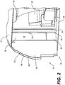
- FIG. 2 shows an exemplary representation of the interior of aircraft 10, where the aircraft interior includes bulkhead 16 and door 18 and where door 18 is shown to be partially extending across aperture 20 defined in bulkhead 16.
- the aircraft interior may further include baggage compartment 22, furnishings 24, floor 26 and ceiling 27.
- Bulkhead 16 may comprise one or more walls/partitions between first zone 12 and second zone 14.
- Bulkhead 16 may comprise first panel 28 and second panel 30 defining internal cavity 32 therebetween.
- Door 18, may, for example, include a sliding pocket door configured to substantially extend across aperture 20 when in a closed position and be substantially recessed (e.g. stowed) in internal cavity 32 of bulkhead 16 when in an open position.
- Door 18, may extend to and abut against opposing side 33 of aperture 20 when in the open position. Accordingly, door 18 may be used to open and close aperture 20 by being moved laterally in and out of aperture 20 during opening and closing of door 18.
- Door 18 may include handle 34 and pressure-relief element 36.
- Pressure-relief element 36 may be configured to provide blow-out functionality during a rapid decompression event in one of first zone 12 and second zone 14. Accordingly, pressure-relief element 36 may comprise a panel releasably retained such that pressure-relief element 36 may become released upon presence of a predetermined pressure differential across pressure-relief element 36 (e.g. between first zone 12 and second zone 14). The release of pressure-relief element 36 may create an opening between first zone 12 and second zone 14 and thereby reduce or substantially eliminate any pressure differential between first zone 12 and second zone 14. Pressure-relief element 36 may form at least part of door 18. For example, door 18 may comprise main portion 38 configured to cooperate with pressure-relief element 36 in opening and closing aperture 20.
- door 18 may consist entirely of pressure-relief element 36 without main portion 38.
- pressure-relief element 36 may be sized to occupy the entire area of door 18 or only a partial fraction of the area of door 18.
- the size of pressure-relief element 36 relative to door 18 may depend on the size of door 18 and whether door 18 is used for opening and closing an occupant passage or another type of aperture 20 in bulkhead 16.
- pressure-relief element 36 may be sized and retained to provide a suitable pressure-relief function during a rapid decompression event.
- pressure-relief element 36 may comprise a footer (e.g. lower part) of door 18.
- pressure-relief element 36 could include another part (e.g. top and/or middle) of door 18.
- FIGS. 3A and 3B respectively show a front elevation view of door 18 in a closed position ( FIG. 3A ) and in an open position ( FIG. 3B ).
- First bulkhead panel 28 has been removed for the purpose of illustrating the inside of cavity 32.
- Interface 40 may be used to couple door 18 to the aircraft interior.
- Interface 40 may also be configured to permit movement of door 18 between open and closed positions.
- interface 40 may be configured to guide door 18 laterally in and out of aperture 20 during opening and closing of door 18.
- Interface 40 may be configured to permit non-destructive de-coupling of pressure-relief element 36 from the aircraft interior.
- interface 40 may comprise footer carriage 42 coupled to pressure-relief element 36 and movable along footer track 44 in order to guide pressure-relief element 36 laterally in and out of aperture 20.
- Interface 40 may also comprise main carriage 46 coupled to main portion 38 of door 18 and movable along main tracks 48 in order to guide main portion 38 laterally in and out of aperture 20 during opening and closing of door 18.
- Link 50 e.g. bar
- Link 50 may provide a physical connection between footer carriage 42 and main carriage 46 to permit substantially synchronized movement of footer carriage 42 and main carriage 46 during opening and closing of door 18.
- link 50 may be coupled to footer carriage 42 via bracket 51.
- Link 50 may also permit an opening/closing force being applied to handle 34 on main portion 38 of door 18 to be transmitted to footer carriage 42 and hence to pressure-relief element 36.
- Footer track 44 and main tracks 48 may be non-parallel.
- footer track 44 may be substantially parallel to floor 26 and main tracks 48 may be non-parallel (e.g. inclined) relative to floor 26.
- the inclination of main tracks 48 may be provided to cause downward movement of main portion 38 during opening of door 18 to compensate for the decreasing height of ceiling 27 (due to the substantially circular cross-sectional shape of the fuselage of aircraft 10 as door 18 moves laterally toward the open position.
- a sliding connection may be provided between link 50 and footer carriage 42 and/or main carriage 46 to permit relative vertical movement between footer carriage 42 and main carriage 46 during opening and closing of door 18.
- main portion 38 or door 18 may include internal pocket 52 configured for receiving pressure-relief element 36 during opening of door 18.
- main portion 38 of door 18 may be opened and undergoes downward (i.e. toward floor 26) movement under the guidance of main tracks 48, pressure-relief element 36 may be received in pocket 52 so that the overall height of door 18 can be reduced to consequently permit stowage of door 18 into cavity 32.
- main portion 38 and pressure-relief element 36 could be offset relative to each other (e.g. not in the same plane) in order to permit relative vertical movement between each other.
- door 18 may be provided to assist an occupant in opening and closing of door 18 (e.g. automatically open/close door 18) and/or also assist in holding door 18 in the desired open position or closed position.
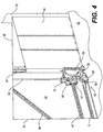
- FIG. 4 shows footer carriage 42 being coupled to pressure-relief element 36.
- Footer carriage 42 may be releasably coupled to a lower part (e.g. closer to floor 26) of pressure-relief element 36.
- Footer carriage 42 may be configured to cause vertical movement of pressure-relief element 36 during opening and closing of door 18.
- footer carriage 42 may be configured to cause pressure-relief element 36 to move downward (i.e. toward floor 26) relative to the aircraft interior during closing of door 18.
- footer carriage 42 may be configured to cause controlled downward movement of pressure-relief element 36 during closing of door 18 as door 18 approaches a fully closed position.
- Footer carriage 42 may also be configured to cause controlled upward movement of pressure-relief element 36 relative to floor 26 during opening of door 18 upon initial opening of door 18 from a fully closed position. Accordingly, in the open position, a clearance shown as CLR in FIG. 3B may be provided between floor 26 and door 18.
- Footer carriage 42 may comprise carriage body 54 movable vertically (i.e. upward and downward-relative to floor 26) in relation to carriage support 56 and hence in relation to footer track 44.
- Carriage support 56 may comprise one or more rolling and/or sliding and/or other types of member 57 adapted to cooperate with track 44 to thereby permit movement of carriage 42 along track 44.
- FIG. 5 shows a front elevation view of footer carriage 42.
- Footer carriage 42 may also comprise sliding member 58 along which the movement of carriage body 54 relative to carriage support 56 may be guided.
- Footer carriage 42 may also comprise foot portion 59 having cam surface 60 configured to interact with roller 62 in order to cause vertical movement of carriage body 54 relative to carriage support 56 and hence vertical movement of pressure-relief element 36 relative to floor 26 (e.g. aircraft interior).
- Roller 62 may be secured to first bulkhead panel 28 and/or second bulkhead panel 30 and/or other part of the aircraft interior. Consequently, upward/vertical movement of pressure-relief element 36 may result in clearance CLR between pressure-relief element 36 and floor 26 (see FIG.
- clearance CLR may depend on the diameter and position of roller 62. Accordingly, roller 62 may be sized and positioned to provide a clearance CLR suitable for clearing components disposed inside bulkhead below door 18. In an exemplary embodiment, the value of clearance CLR may be about 6 cm from floor 26. The value of clearance CLR may also be selected to reduce friction between pressure-relief element 36 and floor 26 or any covering (e.g. carpet) that may be disposed on floor 36. Accordingly, the value of clearance CLR may, for example, be in the range of about 2 cm to about 10 cm.
- Sliding member 58 may extend through one or more bushings 64 configured to permit sliding movement of sliding member 58 through bushings 64 secured to carriage support 56. While sliding member 58 may permit upward and downward movement of footer carriage 42 relative to carriage support 56, sliding member 58 may also be configure to permit lateral movement of footer carriage 42 relative to carriage support 56.
- sliding member 58 may be oriented at an angle ⁇ from the vertical direction (i.e. perpendicular to floor 26) such as in a range from about 5 degrees to about 20 degrees from the vertical direction. In an exemplary embodiment, sliding member 58 may be oriented at an angle in the range of 12 to 18 degrees such as 16 degrees from vertical, for example.
- cam surface 60 may have a profile comprising a substantially linear portion that is inclined relative to the horizontal direction (i.e. relative to floor 26).
- a substantially linear portion of cam surface 60 may be inclined at an angle of about 10 to 15 degrees relative to floor 26 but other inclination angles such as between 5 and 30 degrees may also be suitable.
- cam surface 60 could comprise a curved portion to provide a varying rate of vertical movement relative to horizontal movement during opening and closing of door 18.
- Controlled downward and lateral movement of pressure-relief element 36 during closing of door 18 may permit for a closer fit to be achieved between pressure-relief element 36 and floor 26 and also between pressure-relief element 36 and opposing side 33 of aperture 20 and thereby substantially prevent (e.g. minimize) significant light bleed between adjacent first zone 12 and second zone 14.
- pressure-relief element 36 may abut against floor 26 while in the closed position
- the upward movement of pressure-relief element 36 upon initial opening of door 18 may substantially prevent dragging of pressure-relief element 36 against floor 26 during opening and closing of door 18.
- the upward movement of pressure-relief element 36 upon initial opening of door 18 may also substantially prevent abrasion of the lower part of pressure-relief element 36 and/or floor 26.
- footer carriage 42 is applied to pressure-relief element 36
- the controlled movement provided via footer carriage 42 could, for example, be applied to any upper or lower portion of door 18, which may or may not have a pressure-relief function.
- such controlled movement could alternatively be provided to a header portion of door 18 for the purpose of preventing significant light bleed between door 18 and ceiling 27.
- FIGS. 6 and 7 show an exemplary means for releasably coupling pressure-relief element 36 and footer carriage 42 and also for permitting non-destructive de-coupling of pressure-relief element 36 and footer carriage 42 in the event rapid decompression.
- pressure-relief element 36 may be retained by one or more magnetic forces calibrated to permit release of pressure-relief element 36 upon the presence of a predetermined pressure differential across pressure-relief element 36.
- the predetermined pressure differential may be selected such that, for example, pressure-relief element 36 would become released before any other part of door 18 and/or bulkhead 16 would become damaged and/or become flying debris that could cause injury to aircraft occupants.
- the magnetic force retaining pressure-relief element 36 may be provided by one or more magnets 66 cooperating with one or more corresponding members 68 comprising a magnetic material being attracted to magnets 66.
- Magnets 66 may be disposed on footer carriage 42 and members 68 may be disposed on pressure-relief element 36 or vice versa.
- footer carriage 42 could comprise both magnet(s) 66 and member(s) 68 while pressure-relief element 36 also comprises both magnet(s) 66 and member(s) 68 configured to cooperate with those on footer carriage 42.
- Members 68 may comprise a unitary component provided with one or more surfaces suitable for cooperating with corresponding magnets 66.
- Members 68 may be made of any suitable magnetic material(s) (i.e. attracted by a magnet) causing members 68 to be attracted to corresponding magnets 66.
- members 68 may comprise one or more metallic (e.g. steel) plates attracted to by magnets 66.
- the size, type and strength of magnets 66 and the size/type of members 68 may be selected to produce the calibrated magnetic force(s) required to produce the desired pressure-relief function of pressure-relief element 36.
- magnets 66 may comprise one or more permanent magnets and/or one or more electromagnets.
- magnets 66 include one or more electromagnets
- the magnetic force of such electromagnets may be electrically controlled and/or may be deactivated in the event of a rapid decompression event.
- Members 68 may, for example comprise ferromagnetic material(s) and/or any suitable material(s) causing members 68 to be attracted to magnets 66 and provide the desired magnetic retaining force between footer carriage 42 and pressure-relief element 36.
- pressure-relief element 36 could comprise any portion(s) including the entirety of door 18 and not necessarily a footer of door 18. Accordingly, depending on the position and size of pressure-relief element 36, the magnetic retention force could be provided between the pressure-relief element 36 and any other suitable part of aircraft interior. Alternatively, the magnetic retention force could be provided between pressure-relief element 36 and main portion 38 of door 18.
- Lanyard 70 may be provided to prevent pressure-relief element 36 from becoming flying debris upon release of the pressure-relief element 36 due to the predetermined pressure differential. Lanyard 70 may permit pressure-relief element 36 to become released (e.g. create an opening between first zone 12 and second zone 14 for the purpose of equalizing the pressure differential) while remaining attached to footer carriage 42 or any other suitable part of the aircraft interior. First end 72 of lanyard 70 may be secured to pressure-relief element 36 while second end 74 of lanyard 70 may be secured to footer carriage 42. Lanyard 70 may extend through lock 76 and channel 78 of footer carriage 42 so that second end 74 of lanyard 70 would become retained by lock 76 in the event of a release (e.g. blow-out) of pressure-relief element 36.
- a release e.g. blow-out
- Support ramp 77 may be secured to the aircraft interior and be provided for supporting pressure-relief element 36 when door 18 is in the open position and also during movement of door 18 during opening and closing.
- rollers 79 may be provided on footer carriage 42 to engage with support ramp 77.
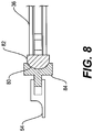
- Footer carriage 42 and pressure-relief element 36 may also comprise self-locating features 80, 82 that may facilitate the installation of pressure-relief element 36 and also relative positioning of magnets 66 and members 68.
- Such self locating features may include one or more recesses 80 and corresponding one or more protrusions 82.
- FIG. 8 shows a cross-section view of the self-locating features 80, 82 taken along line 8-8 of FIG. 5 .
- Recess 80 and corresponding protrusions 82 may have complementary shapes. While the exemplary embodiment illustrates self-locating features 80, 82 having circular profiles, it is understood that other suitable shapes and profiles could also be used instead of or in addition to those shown.
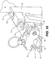
- FIGS. 9 and 10 show exemplary means for adjusting the position of pressure-relief element 36 in relation to aircraft interior (e.g. floor 26).
- footer carriage 42 may be configured to provide position adjustment of pressure-relief element 36 relative to the aircraft interior in three degrees of freedom, namely tilt (e.g. substantially within a plane of door 18), vertical (e.g. substantially perpendicular to floor 26) and lateral (e.g. substantially parallel to floor 26).
- the position adjustment of pressure-relief element 36 may permit reduction in light bleed around pressure-relief element 36 when in the closed position.
- Tilt adjustment of pressure-relief element 36 relative to the aircraft interior may be made via adjustable holder 84 of footer carriage 42 to adjust the parallelism of a lower edge of pressure-relief element 36 with floor 26.
- Magnets 66 and or magnetic members 68 may be secured to adjustable holder 84.
- Adjustable holder 84 may be pivotally coupled to carriage body 54 at pivot pin 86.
- adjustable holder 84 may comprise a tongue (not shown) extending inside carriage body 54 and through which pivot pin 86 may extend.
- Adjustable holder 84 may also be coupled to carriage body 54 via tilt bolt 88. Tilt bolt 88 may be threaded into pad 90 of carriage body 54. A head of tilt bolt 88 may be secured (e.g.
- Tilt bolt 88 may comprise an "Allen" type bolt or other suitable type of fastener, which may be threaded.
- One of flanges 92 may comprise hole 94 permitting insertion of a suitable tool/wrench for engaging and turning tilt bolt 88. Turning of tilt bolt 88 may cause the head of tilt bolt 88 to engage flanges 92 to cause pivoting of adjustable holder 84 about pivot pin 86 and consequently cause tilting of pressure-relief element 36 coupled to footer carriage 42.
- Foot portion 59 may be pivotally coupled to carriage body 54 at foot pivot 96.
- Foot portion 59 may comprise foot pin 98 secured thereto and into which bolt 100 may be threaded.
- a head of bolt 100 may be secured (e.g. sandwiched) between flanges 102, which may be secured to carriage body 54.
- Bolt 100 may comprise an "Allen" type bolt or other suitable type of fastener which may be threaded.
- One of flanges 102 may comprise hole 104 permitting insertion of a suitable tool/wrench for engaging and turning bolt 100.
- Turning of bolt 100 may cause the head of bolt 100 to engage flanges 102 to cause relative pivoting of adjustable foot portion 59 and carriage body 54 about foot pivot 96 and, through the interaction of cam surface 60 and roller 62, cause vertical movement carriage body 54 relative to carriage support 56. Such vertical movement of carriage body 54 relative to carriage support 56 may consequently cause vertical movement of pressure-relief element 36 coupled to footer carriage 42.
- FIG. 10 and 11 illustrate how lateral position adjustment of pressure-relief element 36 relative to the aircraft interior (e.g. floor 26, aperture 20) may be made. Lateral adjustment may be made by adjusting the position of carriage support 56 relative to bracket 51. Carriage support 56 and bracket 51 may be slidably coupled to each other according to known or other methods. Lateral adjustment of carriage support 56 may be made along line 106 toward either an outboard direction (e.g. toward a closed position of door 18) or inboard direction (e.g. toward an open position of door 18) by turning bolt 108, which may be threaded into bracket 51. Bolt 108 may be received in slot 110 formed in carriage support 56.
- an outboard direction e.g. toward a closed position of door 18
- inboard direction e.g. toward an open position of door 18
- slot 110 may be suitably shaped so that head of bolt 108 is engaged in slot 110 as bolt 108 is turned to cause relative lateral movement between bracket 51 and carriage support 56.
- Bolt 108 may comprise an "Allen" type bolt or other suitable type of fastener which may be threaded. Accordingly, slot 110 may have a substantially T-shaped profile.
- Hole 112 may be provided in carriage support 56 to permit insertion of a suitable tool/wrench for engaging and turning bolt 108. Turning of bolt 108 may cause relative movement between carriage support 56 and bracket 51 and consequently cause lateral movement of pressure-relief element 36 coupled to footer carriage 42.
- FIGS. 12 and 13 illustrate an alternate exemplary embodiment of means for releasably coupling pressure-relief element 36 to footer carriage 42 using one or more magnetic retaining forces.
- magnets 66 may be disposed on pressure-relief element 36 and members 68 may be disposed on footer carriage 42.
- adjustable holder 84 may comprise members 68 instead of magnets 66.
- Self-locating features 80 and 82 could be similarly disposed on pressure-relief element 36 and adjustable holder 84 respectively.
- protrusions 82 could instead be disposed on adjustable holder 84 and/or that corresponding recess 80 could instead be disposed on pressure-relief element 36.
- FIGS. 14 and 15 show the attachment of link 50 between main carriage 46 and footer carriage 42.
- Link 50 may be in the form of a structural member (e.g. bar) that may provide a mechanical coupling of footer carriage 42 and main carriage 46. Such mechanical coupling may permit substantially synchronized lateral movement of footer carriage 42 and main carriage 46 during opening and closing of door 18.
- link 50 may also permit an opening/closing force being applied to main portion 38 of door 18 (e.g. via handle 34 by an occupant or otherwise) to be transmitted to footer carriage 42 and hence pressure-relief element 36.
- a sliding connection through main carriage 46 may be provided so that vertical movement of main carriage 46 relative to footer carriage 42 may be permitted during opening and closing of door 18.
- the sliding connection through main carriage 46 may be provided by use of suitable bushings 114 permitting sliding of link 50 through main carriage 46.
- connection of link 50 with footer carriage 42 may not provide any relative movement between link 50 and footer carriage 42.
- a sliding connection for link 50 could instead or additionally be provided in footer carriage 42 and thereby permit relative movement between link 50 and footer carriage 42.
- door assemblies including door 18 and interface 40 may be used to provide blow-out functionality during a rapid decompression event.
- such door assemblies as described herein may also provide reduced light bleed between first zone 12 and second zone 14 of aircraft 10.
- door 18 may be opened and closed to provide a barrier between first zone 12 and second zone 14.
- first zone 12 and second zone 14 In the event of a rapid decompression of either one of first zone 12 and second zone 14 while door 18 is in a closed position, a significant pressure differential could be created across door 18 and also bulkhead 16.
- pressure-relief element 36 of door 18 may become released (e.g. blown-out) in the event that the pressure differential reaches a predetermined level.
- the magnetic retaining force(s) between pressure-relief element 36 and footer carriage 42 may be calibrated so as to be overcome upon the application of a predetermined pressure differential across pressure-relief element 36.
- the predetermined pressure differential may be selected to be below a threshold where structural damage to other parts of the aircraft interior could occur.
- the release of the magnetic retaining force may cause the lower part of pressure-relief element 36 to initially swing outward (i.e. out of the plane of door 18) upon initial release of pressure-relief element 36 as pressure-relief element 36 begins to form one or more openings between first zone 12 and second zone 14.
- the forming of one or more openings between first zone 12 and second zone 14 by the release of pressure-relief element 36 may substantially reduce or eliminate the pressure differential between first zone 12 and second zone 14.
- pressure-relief element 36 may be attached to footer carriage 42 and/or to other part of the aircraft interior via lanyard 70 (see FIG. 7 ).
- pressure-relief element 36 may simply be re-installed by re-coupling pressure-relief element 36 to footer carriage 42 using magnets 66 and corresponding magnetic members 68.
- Self-aligning features 80 and 82 may be used to properly position pressure-relief element 36 relative to footer carriage 42.
- Door assemblies described herein may also allow relatively low amount of light bleed between first zone 12 and second zone 14.
- Mechanisms and devices described herein may be used to adjust the tilt, vertical position, and lateral position of pressure-relief element 36 so that the position of pressure-relief element 36 within aperture 20 and relative to floor 26 and/or other parts of the aircraft interior may be adjusted to reduce or substantially eliminate gaps and hence the amount of light bleed around pressure-relief element 36.
- Footer carriage 42 may be configured to provide adjustment along three degrees of freedom but it is understood that the door assemblies described herein could be configured to provide adjustment capabilities in more or fewer degrees of freedom depending on specific applications and requirements.
- footer carriage 42 could instead be coupled to a footer or a header portion of door 18 not having a pressure-relief function.
- the vertical movement of pressure-relief element 36 during opening and closing of door 18 may also contribute to reducing light bleed around pressure-relief element 36.
- the controlled downward and/or lateral movement of pressure-relief element 36 provided by the interaction of cam surface 60 and roller 62 during closing of door 18 may permit for a closer fit to be achieved between pressure-relief element 36 and floor 26 and also between pressure-relief element 36 and opposing side 33 of aperture 20.
- pressure-relief element 36 may be adjusted to abut against floor 26 while in the closed position, the upward movement of pressure-relief element 36 upon initial opening of door 18 may substantially prevent dragging of pressure-relief element 36 against floor 26 during opening and closing of door 18.
- the upward movement of pressure-relief element 36 upon initial opening of door 18 may also substantially prevent abrasion (e.g. damage) of the lower part of pressure-relief element 36 and/or floor 26. Accordingly, the door assemblies described herein may also be relatively quiet during opening and closing.
Landscapes
- Engineering & Computer Science (AREA)
- Aviation & Aerospace Engineering (AREA)
- Mechanical Engineering (AREA)
- Civil Engineering (AREA)
- Structural Engineering (AREA)
- Business, Economics & Management (AREA)
- Emergency Management (AREA)
- Power-Operated Mechanisms For Wings (AREA)
- Special Wing (AREA)
Claims (13)
- Ensemble de porte pour un intérieur d'aéronef, l'ensemble de porte comprenant :une porte (18) destinée à ouvrir et fermer une ouverture (20) entre des zones (12, 14) de l'intérieur d'aéronef, dans lequel la porte (18) comprend une partie principale (38), un élément limiteur de pression (36) en coopération avec la partie principale (38) dans l'ouverture et la fermeture de l'ouverture (20) entre les zones (12, 14) de l'intérieur d'aéronef et formant au moins une partie de la porte (18), l'élément limiteur de pression (36) étant retenu par une force magnétique calibrée pour permettre la libération de l'élément limiteur de pression en présence d'un différentiel de pression prédéterminé à travers l'élément limiteur de pression ; etune interface (40) configurée pour coupler la porte (18) à l'intérieur d'aéronef, dans lequel l'élément limiteur de pression (36) est couplé à l'interface (40) par la force magnétique calibrée.
- Ensemble de porte selon la revendication 1, dans lequel l'interface (40) comprend un chariot (42) mobile le long d'un chemin de roulement (44) attachable à l'intérieur d'aéronef.
- Ensemble de porte selon la revendication 2, dans lequel le chariot (42) comprend un aimant (66) et l'élément limiteur de pression (36) comprend un élément (68) attiré vers l'aimant (66).
- Ensemble de porte selon la revendication 2, dans lequel l'élément limiteur de pression (36) comprend un aimant (66) et le chariot (42) comprend un élément (68) attiré vers l'aimant.
- Ensemble de porte selon l'une quelconque des revendications 2 à 4, dans lequel le chariot (42) comprend un support (84) pour au moins l'un de l'aimant (66) et l'élément (68) attiré vers l'aimant (66), la position du support (84) étant ajustable par rapport à l'intérieur d'aéronef.
- Ensemble de porte selon l'une quelconque des revendications 1 à 5, dans lequel une partie inférieure de l'élément limiteur de pression (36) est couplée à l'interface (40) par la force magnétique calibrée.
- Ensemble de porte selon l'une quelconque des revendications 2 à 6, dans lequel le chemin de roulement (44) est configuré pour guider l'élément limiteur de pression (36) latéralement dans et hors de l'ouverture (20) pendant l'ouverture et la fermeture de la porte (18).
- Ensemble de porte selon l'une quelconque des revendications 1 à 7, comprenant des fonctions d'auto-positionnement en coopération (80, 82) destinées au positionnement relatif de l'interface (40) et de l'élément limiteur de pression (36).
- Ensemble de porte selon l'une quelconque des revendications 1 à 8, dans lequel l'interface induit un mouvement vers le bas de l'élément limiteur de pression (36) pendant la fermeture de la porte (18).
- Ensemble de porte selon l'une quelconque des revendications 1 à 9, dans lequel l'élément limiteur de pression (36) comprend un pied.
- Ensemble de porte selon l'une quelconque des revendications 1 à 10, dans lequel la porte (18) est une porte coulissante escamotable.
- Ensemble de porte selon l'une quelconque des revendications 1 à 11, comprenant un aimant permanent.
- Aéronef comprenant l'ensemble de porte selon l'une quelconque des revendications 1 à 12.
Applications Claiming Priority (1)
| Application Number | Priority Date | Filing Date | Title |
|---|---|---|---|
| PCT/IB2012/001600 WO2014027215A1 (fr) | 2012-08-17 | 2012-08-17 | Ensemble porte pour l'intérieur d'un avion |
Publications (2)
| Publication Number | Publication Date |
|---|---|
| EP2885205A1 EP2885205A1 (fr) | 2015-06-24 |
| EP2885205B1 true EP2885205B1 (fr) | 2019-04-17 |
Family
ID=46968316
Family Applications (1)
| Application Number | Title | Priority Date | Filing Date |
|---|---|---|---|
| EP12767094.1A Not-in-force EP2885205B1 (fr) | 2012-08-17 | 2012-08-17 | Ensemble porte pour l'intérieur d'un avion |
Country Status (5)
| Country | Link |
|---|---|
| US (1) | US20150210373A1 (fr) |
| EP (1) | EP2885205B1 (fr) |
| CN (1) | CN104583072B (fr) |
| CA (1) | CA2881516A1 (fr) |
| WO (1) | WO2014027215A1 (fr) |
Families Citing this family (12)
| Publication number | Priority date | Publication date | Assignee | Title |
|---|---|---|---|---|
| FR2978121B1 (fr) * | 2011-07-22 | 2016-05-27 | Dassault Aviat | Element de separation pour cabine de plateforme comprenant un mecanisme a bielles de deplacement d'un ouvrant |
| DE102011114643B4 (de) * | 2011-09-30 | 2016-03-24 | Airbus Operations Gmbh | Betätigungsvorrichtung zum Öffnen einer Notausgangsklappe einer Cockpittür |
| WO2015173694A1 (fr) | 2014-05-12 | 2015-11-19 | Bombardier Inc. | Ensemble cloison à porte escamotable pour intérieur d'aéronef |
| EP3090938B1 (fr) * | 2015-05-06 | 2018-04-11 | Airbus Operations GmbH | Système de porte pour l'intérieur d'un aéronef et aéronef comportant un tel système |
| US10029778B2 (en) | 2015-05-22 | 2018-07-24 | Gulfstream Aerospace Corporation | Aircraft door with compressible header |
| CA2989396A1 (fr) | 2015-06-25 | 2016-12-29 | Bombardier Inc. | Cabine d'aeronef et ensemble separation associe |
| US10384760B2 (en) | 2015-07-06 | 2019-08-20 | Gulfstream Aerospace Corporation | Self-adjusting door jamb for an aircraft door |
| EP3168138B1 (fr) * | 2015-11-10 | 2018-06-06 | Airbus Operations GmbH | Ensemble porte d'aéronef |
| US10160532B2 (en) * | 2016-01-21 | 2018-12-25 | Gulfstream Aerospace Corporation | Aircraft door with retractable header |
| CN106121452B (zh) * | 2016-06-27 | 2017-12-26 | 青岛新诚志卓轨道交通装备股份有限公司 | 负压自锁推拉门 |
| EP3290328B1 (fr) * | 2016-09-05 | 2019-07-03 | Airbus Operations GmbH | Unité de porte pour un moyen de transport |
| US11591063B2 (en) * | 2019-06-28 | 2023-02-28 | Dassault Aviation | Separating element for a platform cabin, platform comprising such an element and method for using such an element |
Family Cites Families (30)
| Publication number | Priority date | Publication date | Assignee | Title |
|---|---|---|---|---|
| US3453777A (en) * | 1967-11-07 | 1969-07-08 | American Cyanamid Co | Pressure venting panel assembly |
| US3571977A (en) * | 1969-06-27 | 1971-03-23 | Boeing Co | Access and pressure release door latch mechanism |
| US3579934A (en) * | 1969-09-17 | 1971-05-25 | Engineered Products Co The | Magnetic door catch with riser |
| US3934845A (en) * | 1975-03-17 | 1976-01-27 | Northrop Corporation | Gun bay pressure relief device |
| US4207706A (en) * | 1978-12-05 | 1980-06-17 | Haines Eugene F | Latch control for explosion relief panel |
| FR2548623B1 (fr) * | 1983-07-08 | 1985-10-11 | Aerospatiale | Dispositif de securite pour l'ouverture d'une porte d'aeronef ouvrant vers l'exterieur en cas de surpression a l'interieur de cet aeronef et porte ainsi equipee |
| US4646993A (en) * | 1985-03-04 | 1987-03-03 | The Boeing Company | Sidewall vent valves for a convertible compartment aircraft |
| CA1241517A (fr) * | 1987-03-18 | 1988-09-06 | Kenneth H. Betts | Panneaux et lucarnes de protection contre les ruptures explosives |
| US4911219A (en) * | 1988-05-20 | 1990-03-27 | Dalrymple Jerry M | Pocket door for curved walled enclosures |
| US4989808A (en) | 1989-07-07 | 1991-02-05 | Msa Aircraft Interior Products, Inc. | Sliding pocket door for aircraft use capable of non-destructive blow-out |
| US6186444B1 (en) * | 1999-01-15 | 2001-02-13 | Charles F. Steel | Sliding pocket door for aircraft use capable of nondestructive blow-out and easy access |
| US20020092951A1 (en) * | 2001-01-16 | 2002-07-18 | Asher Haviv | Lock system for aircraft cockpit door |
| CA2424380A1 (fr) * | 2001-09-16 | 2003-03-27 | Mul-T-Lock Security Products Ltd. | Appareil d'acces |
| US20030052227A1 (en) * | 2001-09-17 | 2003-03-20 | Pittman Donald Merve | Protective shield for aircraft cockpit crew |
| US6866226B2 (en) * | 2001-10-04 | 2005-03-15 | Hartwell Corporation | Pressure responsive blowout latch |
| WO2003029585A2 (fr) * | 2001-10-04 | 2003-04-10 | Hartwell Corporation | Pene dormant sensible a la pression |
| US6866227B2 (en) * | 2001-10-04 | 2005-03-15 | Hartwell Corporation | Pressure responsive blowout latch with reservoir |
| US20030127563A1 (en) * | 2001-10-26 | 2003-07-10 | Laconte Richard J. | Differential pressure sensing release system |
| US6823927B2 (en) * | 2003-03-05 | 2004-11-30 | Charles F. Steel | Pocket door with pivoting panel |
| US7032863B1 (en) * | 2004-10-15 | 2006-04-25 | The Boeing Company | Increased security flight deck door strike apparatus and method |
| US7441726B2 (en) * | 2004-12-30 | 2008-10-28 | The Boeing Company | Flight deck security pocket door system |
| US8038100B2 (en) * | 2007-09-21 | 2011-10-18 | Honda Motor Co., Ltd. | Paneled partition with track for linear and rotational movement |
| WO2009058386A2 (fr) * | 2007-11-01 | 2009-05-07 | Adams Rite Aerospace | Mécanisme de verrouillage d'orifice de décompression |
| FR2926534B1 (fr) * | 2008-01-21 | 2010-04-02 | Airbus France | Porte d'aeronef pressurise equipe d'un volet de mise a l'air libre |
| US8458957B2 (en) * | 2009-03-23 | 2013-06-11 | Glidewell Track, Inc. | Sliding pocket door system |
| DE102009025382B4 (de) * | 2009-06-18 | 2017-01-26 | Airbus Operations Gmbh | Dekompressionseinrichtung für ein Luftfahrzeug |
| US8763327B2 (en) * | 2011-10-07 | 2014-07-01 | Honda Motor Co., Ltd. | Paneled partition having a retractable extension |
| FR2990189B1 (fr) * | 2012-05-02 | 2015-01-02 | Airbus Operations Sas | Porte de surpression pour aeronef. |
| US9114869B1 (en) * | 2013-06-05 | 2015-08-25 | The Boeing Company | Decompression panel and latch |
| FR3022884B1 (fr) * | 2014-06-27 | 2016-07-01 | Airbus Operations Sas | Avion equipe d'une trappe interieure d'evacuation integrant un systeme de regulation de pression |
-
2012
- 2012-08-17 US US14/421,625 patent/US20150210373A1/en not_active Abandoned
- 2012-08-17 WO PCT/IB2012/001600 patent/WO2014027215A1/fr active Application Filing
- 2012-08-17 EP EP12767094.1A patent/EP2885205B1/fr not_active Not-in-force
- 2012-08-17 CA CA2881516A patent/CA2881516A1/fr not_active Abandoned
- 2012-08-17 CN CN201280075362.6A patent/CN104583072B/zh not_active Expired - Fee Related
Non-Patent Citations (1)
| Title |
|---|
| None * |
Also Published As
| Publication number | Publication date |
|---|---|
| CA2881516A1 (fr) | 2014-02-20 |
| EP2885205A1 (fr) | 2015-06-24 |
| US20150210373A1 (en) | 2015-07-30 |
| CN104583072B (zh) | 2017-08-15 |
| WO2014027215A1 (fr) | 2014-02-20 |
| CN104583072A (zh) | 2015-04-29 |
Similar Documents
| Publication | Publication Date | Title |
|---|---|---|
| EP2885205B1 (fr) | Ensemble porte pour l'intérieur d'un avion | |
| US11142321B2 (en) | Aircraft door and privacy panel assemblies | |
| US20230174236A1 (en) | Mini suite emergency egress solutions | |
| EP3458363B1 (fr) | Ensemble accoudoir réglable | |
| US7744035B2 (en) | Door for compartment of the baggage-compartment type | |
| BR102016007167B1 (pt) | Sistema divisor de seção | |
| EP3142922B1 (fr) | Ensemble cloison à porte escamotable pour intérieur d'aéronef | |
| US10974834B2 (en) | Separable vehicle cabin privacy partition assemblies which allow for emergency egress | |
| EP3587244A1 (fr) | Porte de cockpit coulissante et rotative et procédé | |
| WO2021084470A1 (fr) | Unité de siège de passager avec porte coulissante à plusieurs voies | |
| EP2828151B1 (fr) | Séparateur de classe d'aéronef | |
| CA2914149C (fr) | Ensemble surmontoir electroluminescent pour zone de transition, dans une cabine interieure d'un aeronef | |
| US20220355935A1 (en) | Passenger seat unit with foldable door | |
| EP4173953A1 (fr) | Systèmes et procédés de verrouillage réglable | |
| US11370547B2 (en) | Mobile class divider for aircraft cabin | |
| US11414907B2 (en) | Door assembly and method for making the same, and aircraft including a door assembly | |
| US20230417085A1 (en) | Adjustable latch systems and methods | |
| KR101047403B1 (ko) | 상용버스용 회전식 락커 |
Legal Events
| Date | Code | Title | Description |
|---|---|---|---|
| PUAI | Public reference made under article 153(3) epc to a published international application that has entered the european phase |
Free format text: ORIGINAL CODE: 0009012 |
|
| 17P | Request for examination filed |
Effective date: 20150212 |
|
| AK | Designated contracting states |
Kind code of ref document: A1 Designated state(s): AL AT BE BG CH CY CZ DE DK EE ES FI FR GB GR HR HU IE IS IT LI LT LU LV MC MK MT NL NO PL PT RO RS SE SI SK SM TR |
|
| AX | Request for extension of the european patent |
Extension state: BA ME |
|
| DAX | Request for extension of the european patent (deleted) | ||
| STAA | Information on the status of an ep patent application or granted ep patent |
Free format text: STATUS: EXAMINATION IS IN PROGRESS |
|
| 17Q | First examination report despatched |
Effective date: 20171120 |
|
| GRAP | Despatch of communication of intention to grant a patent |
Free format text: ORIGINAL CODE: EPIDOSNIGR1 |
|
| STAA | Information on the status of an ep patent application or granted ep patent |
Free format text: STATUS: GRANT OF PATENT IS INTENDED |
|
| INTG | Intention to grant announced |
Effective date: 20181011 |
|
| GRAS | Grant fee paid |
Free format text: ORIGINAL CODE: EPIDOSNIGR3 |
|
| GRAJ | Information related to disapproval of communication of intention to grant by the applicant or resumption of examination proceedings by the epo deleted |
Free format text: ORIGINAL CODE: EPIDOSDIGR1 |
|
| GRAL | Information related to payment of fee for publishing/printing deleted |
Free format text: ORIGINAL CODE: EPIDOSDIGR3 |
|
| STAA | Information on the status of an ep patent application or granted ep patent |
Free format text: STATUS: EXAMINATION IS IN PROGRESS |
|
| GRAR | Information related to intention to grant a patent recorded |
Free format text: ORIGINAL CODE: EPIDOSNIGR71 |
|
| STAA | Information on the status of an ep patent application or granted ep patent |
Free format text: STATUS: GRANT OF PATENT IS INTENDED |
|
| GRAA | (expected) grant |
Free format text: ORIGINAL CODE: 0009210 |
|
| STAA | Information on the status of an ep patent application or granted ep patent |
Free format text: STATUS: THE PATENT HAS BEEN GRANTED |
|
| INTC | Intention to grant announced (deleted) | ||
| INTG | Intention to grant announced |
Effective date: 20190306 |
|
| AK | Designated contracting states |
Kind code of ref document: B1 Designated state(s): AL AT BE BG CH CY CZ DE DK EE ES FI FR GB GR HR HU IE IS IT LI LT LU LV MC MK MT NL NO PL PT RO RS SE SI SK SM TR |
|
| REG | Reference to a national code |
Ref country code: GB Ref legal event code: FG4D |
|
| REG | Reference to a national code |
Ref country code: CH Ref legal event code: EP |
|
| REG | Reference to a national code |
Ref country code: DE Ref legal event code: R096 Ref document number: 602012059097 Country of ref document: DE |
|
| REG | Reference to a national code |
Ref country code: AT Ref legal event code: REF Ref document number: 1121253 Country of ref document: AT Kind code of ref document: T Effective date: 20190515 Ref country code: IE Ref legal event code: FG4D |
|
| REG | Reference to a national code |
Ref country code: NL Ref legal event code: MP Effective date: 20190417 |
|
| REG | Reference to a national code |
Ref country code: LT Ref legal event code: MG4D |
|
| PG25 | Lapsed in a contracting state [announced via postgrant information from national office to epo] |
Ref country code: NL Free format text: LAPSE BECAUSE OF FAILURE TO SUBMIT A TRANSLATION OF THE DESCRIPTION OR TO PAY THE FEE WITHIN THE PRESCRIBED TIME-LIMIT Effective date: 20190417 |
|
| PG25 | Lapsed in a contracting state [announced via postgrant information from national office to epo] |
Ref country code: ES Free format text: LAPSE BECAUSE OF FAILURE TO SUBMIT A TRANSLATION OF THE DESCRIPTION OR TO PAY THE FEE WITHIN THE PRESCRIBED TIME-LIMIT Effective date: 20190417 Ref country code: HR Free format text: LAPSE BECAUSE OF FAILURE TO SUBMIT A TRANSLATION OF THE DESCRIPTION OR TO PAY THE FEE WITHIN THE PRESCRIBED TIME-LIMIT Effective date: 20190417 Ref country code: LT Free format text: LAPSE BECAUSE OF FAILURE TO SUBMIT A TRANSLATION OF THE DESCRIPTION OR TO PAY THE FEE WITHIN THE PRESCRIBED TIME-LIMIT Effective date: 20190417 Ref country code: FI Free format text: LAPSE BECAUSE OF FAILURE TO SUBMIT A TRANSLATION OF THE DESCRIPTION OR TO PAY THE FEE WITHIN THE PRESCRIBED TIME-LIMIT Effective date: 20190417 Ref country code: PT Free format text: LAPSE BECAUSE OF FAILURE TO SUBMIT A TRANSLATION OF THE DESCRIPTION OR TO PAY THE FEE WITHIN THE PRESCRIBED TIME-LIMIT Effective date: 20190817 Ref country code: NO Free format text: LAPSE BECAUSE OF FAILURE TO SUBMIT A TRANSLATION OF THE DESCRIPTION OR TO PAY THE FEE WITHIN THE PRESCRIBED TIME-LIMIT Effective date: 20190717 Ref country code: AL Free format text: LAPSE BECAUSE OF FAILURE TO SUBMIT A TRANSLATION OF THE DESCRIPTION OR TO PAY THE FEE WITHIN THE PRESCRIBED TIME-LIMIT Effective date: 20190417 Ref country code: SE Free format text: LAPSE BECAUSE OF FAILURE TO SUBMIT A TRANSLATION OF THE DESCRIPTION OR TO PAY THE FEE WITHIN THE PRESCRIBED TIME-LIMIT Effective date: 20190417 |
|
| PGFP | Annual fee paid to national office [announced via postgrant information from national office to epo] |
Ref country code: FR Payment date: 20190822 Year of fee payment: 8 Ref country code: DE Payment date: 20190822 Year of fee payment: 8 |
|
| PG25 | Lapsed in a contracting state [announced via postgrant information from national office to epo] |
Ref country code: LV Free format text: LAPSE BECAUSE OF FAILURE TO SUBMIT A TRANSLATION OF THE DESCRIPTION OR TO PAY THE FEE WITHIN THE PRESCRIBED TIME-LIMIT Effective date: 20190417 Ref country code: PL Free format text: LAPSE BECAUSE OF FAILURE TO SUBMIT A TRANSLATION OF THE DESCRIPTION OR TO PAY THE FEE WITHIN THE PRESCRIBED TIME-LIMIT Effective date: 20190417 Ref country code: GR Free format text: LAPSE BECAUSE OF FAILURE TO SUBMIT A TRANSLATION OF THE DESCRIPTION OR TO PAY THE FEE WITHIN THE PRESCRIBED TIME-LIMIT Effective date: 20190718 Ref country code: BG Free format text: LAPSE BECAUSE OF FAILURE TO SUBMIT A TRANSLATION OF THE DESCRIPTION OR TO PAY THE FEE WITHIN THE PRESCRIBED TIME-LIMIT Effective date: 20190717 Ref country code: RS Free format text: LAPSE BECAUSE OF FAILURE TO SUBMIT A TRANSLATION OF THE DESCRIPTION OR TO PAY THE FEE WITHIN THE PRESCRIBED TIME-LIMIT Effective date: 20190417 |
|
| REG | Reference to a national code |
Ref country code: AT Ref legal event code: MK05 Ref document number: 1121253 Country of ref document: AT Kind code of ref document: T Effective date: 20190417 |
|
| PG25 | Lapsed in a contracting state [announced via postgrant information from national office to epo] |
Ref country code: IS Free format text: LAPSE BECAUSE OF FAILURE TO SUBMIT A TRANSLATION OF THE DESCRIPTION OR TO PAY THE FEE WITHIN THE PRESCRIBED TIME-LIMIT Effective date: 20190817 |
|
| PGFP | Annual fee paid to national office [announced via postgrant information from national office to epo] |
Ref country code: GB Payment date: 20190821 Year of fee payment: 8 |
|
| REG | Reference to a national code |
Ref country code: DE Ref legal event code: R097 Ref document number: 602012059097 Country of ref document: DE |
|
| PG25 | Lapsed in a contracting state [announced via postgrant information from national office to epo] |
Ref country code: CZ Free format text: LAPSE BECAUSE OF FAILURE TO SUBMIT A TRANSLATION OF THE DESCRIPTION OR TO PAY THE FEE WITHIN THE PRESCRIBED TIME-LIMIT Effective date: 20190417 Ref country code: RO Free format text: LAPSE BECAUSE OF FAILURE TO SUBMIT A TRANSLATION OF THE DESCRIPTION OR TO PAY THE FEE WITHIN THE PRESCRIBED TIME-LIMIT Effective date: 20190417 Ref country code: EE Free format text: LAPSE BECAUSE OF FAILURE TO SUBMIT A TRANSLATION OF THE DESCRIPTION OR TO PAY THE FEE WITHIN THE PRESCRIBED TIME-LIMIT Effective date: 20190417 Ref country code: SK Free format text: LAPSE BECAUSE OF FAILURE TO SUBMIT A TRANSLATION OF THE DESCRIPTION OR TO PAY THE FEE WITHIN THE PRESCRIBED TIME-LIMIT Effective date: 20190417 Ref country code: AT Free format text: LAPSE BECAUSE OF FAILURE TO SUBMIT A TRANSLATION OF THE DESCRIPTION OR TO PAY THE FEE WITHIN THE PRESCRIBED TIME-LIMIT Effective date: 20190417 Ref country code: DK Free format text: LAPSE BECAUSE OF FAILURE TO SUBMIT A TRANSLATION OF THE DESCRIPTION OR TO PAY THE FEE WITHIN THE PRESCRIBED TIME-LIMIT Effective date: 20190417 |
|
| PLBE | No opposition filed within time limit |
Free format text: ORIGINAL CODE: 0009261 |
|
| STAA | Information on the status of an ep patent application or granted ep patent |
Free format text: STATUS: NO OPPOSITION FILED WITHIN TIME LIMIT |
|
| PG25 | Lapsed in a contracting state [announced via postgrant information from national office to epo] |
Ref country code: IT Free format text: LAPSE BECAUSE OF FAILURE TO SUBMIT A TRANSLATION OF THE DESCRIPTION OR TO PAY THE FEE WITHIN THE PRESCRIBED TIME-LIMIT Effective date: 20190417 Ref country code: SM Free format text: LAPSE BECAUSE OF FAILURE TO SUBMIT A TRANSLATION OF THE DESCRIPTION OR TO PAY THE FEE WITHIN THE PRESCRIBED TIME-LIMIT Effective date: 20190417 |
|
| 26N | No opposition filed |
Effective date: 20200120 |
|
| PG25 | Lapsed in a contracting state [announced via postgrant information from national office to epo] |
Ref country code: TR Free format text: LAPSE BECAUSE OF FAILURE TO SUBMIT A TRANSLATION OF THE DESCRIPTION OR TO PAY THE FEE WITHIN THE PRESCRIBED TIME-LIMIT Effective date: 20190417 |
|
| PG25 | Lapsed in a contracting state [announced via postgrant information from national office to epo] |
Ref country code: MC Free format text: LAPSE BECAUSE OF FAILURE TO SUBMIT A TRANSLATION OF THE DESCRIPTION OR TO PAY THE FEE WITHIN THE PRESCRIBED TIME-LIMIT Effective date: 20190417 Ref country code: CH Free format text: LAPSE BECAUSE OF NON-PAYMENT OF DUE FEES Effective date: 20190831 Ref country code: LI Free format text: LAPSE BECAUSE OF NON-PAYMENT OF DUE FEES Effective date: 20190831 Ref country code: LU Free format text: LAPSE BECAUSE OF NON-PAYMENT OF DUE FEES Effective date: 20190817 Ref country code: SI Free format text: LAPSE BECAUSE OF FAILURE TO SUBMIT A TRANSLATION OF THE DESCRIPTION OR TO PAY THE FEE WITHIN THE PRESCRIBED TIME-LIMIT Effective date: 20190417 |
|
| REG | Reference to a national code |
Ref country code: BE Ref legal event code: MM Effective date: 20190831 |
|
| PG25 | Lapsed in a contracting state [announced via postgrant information from national office to epo] |
Ref country code: IE Free format text: LAPSE BECAUSE OF NON-PAYMENT OF DUE FEES Effective date: 20190817 |
|
| PG25 | Lapsed in a contracting state [announced via postgrant information from national office to epo] |
Ref country code: BE Free format text: LAPSE BECAUSE OF NON-PAYMENT OF DUE FEES Effective date: 20190831 |
|
| REG | Reference to a national code |
Ref country code: DE Ref legal event code: R119 Ref document number: 602012059097 Country of ref document: DE |
|
| GBPC | Gb: european patent ceased through non-payment of renewal fee |
Effective date: 20200817 |
|
| PG25 | Lapsed in a contracting state [announced via postgrant information from national office to epo] |
Ref country code: CY Free format text: LAPSE BECAUSE OF FAILURE TO SUBMIT A TRANSLATION OF THE DESCRIPTION OR TO PAY THE FEE WITHIN THE PRESCRIBED TIME-LIMIT Effective date: 20190417 |
|
| PG25 | Lapsed in a contracting state [announced via postgrant information from national office to epo] |
Ref country code: HU Free format text: LAPSE BECAUSE OF FAILURE TO SUBMIT A TRANSLATION OF THE DESCRIPTION OR TO PAY THE FEE WITHIN THE PRESCRIBED TIME-LIMIT; INVALID AB INITIO Effective date: 20120817 Ref country code: MT Free format text: LAPSE BECAUSE OF FAILURE TO SUBMIT A TRANSLATION OF THE DESCRIPTION OR TO PAY THE FEE WITHIN THE PRESCRIBED TIME-LIMIT Effective date: 20190417 Ref country code: DE Free format text: LAPSE BECAUSE OF NON-PAYMENT OF DUE FEES Effective date: 20210302 Ref country code: FR Free format text: LAPSE BECAUSE OF NON-PAYMENT OF DUE FEES Effective date: 20200831 |
|
| PG25 | Lapsed in a contracting state [announced via postgrant information from national office to epo] |
Ref country code: GB Free format text: LAPSE BECAUSE OF NON-PAYMENT OF DUE FEES Effective date: 20200817 |
|
| PG25 | Lapsed in a contracting state [announced via postgrant information from national office to epo] |
Ref country code: MK Free format text: LAPSE BECAUSE OF FAILURE TO SUBMIT A TRANSLATION OF THE DESCRIPTION OR TO PAY THE FEE WITHIN THE PRESCRIBED TIME-LIMIT Effective date: 20190417 |