EP2884846B1 - A roller system adapted to be used in relation to a flattening apparatus for flattening foodstuff - Google Patents
A roller system adapted to be used in relation to a flattening apparatus for flattening foodstuff Download PDFInfo
- Publication number
- EP2884846B1 EP2884846B1 EP13755942.3A EP13755942A EP2884846B1 EP 2884846 B1 EP2884846 B1 EP 2884846B1 EP 13755942 A EP13755942 A EP 13755942A EP 2884846 B1 EP2884846 B1 EP 2884846B1
- Authority
- EP
- European Patent Office
- Prior art keywords
- outwardly protruding
- protruding surface
- roller system
- roller
- flattening
- Prior art date
- Legal status (The legal status is an assumption and is not a legal conclusion. Google has not performed a legal analysis and makes no representation as to the accuracy of the status listed.)
- Active
Links
Images



Classifications
-
- B—PERFORMING OPERATIONS; TRANSPORTING
- B30—PRESSES
- B30B—PRESSES IN GENERAL
- B30B5/00—Presses characterised by the use of pressing means other than those mentioned in the preceding groups
- B30B5/04—Presses characterised by the use of pressing means other than those mentioned in the preceding groups wherein the pressing means is in the form of an endless band
- B30B5/06—Presses characterised by the use of pressing means other than those mentioned in the preceding groups wherein the pressing means is in the form of an endless band co-operating with another endless band
-
- A—HUMAN NECESSITIES
- A22—BUTCHERING; MEAT TREATMENT; PROCESSING POULTRY OR FISH
- A22C—PROCESSING MEAT, POULTRY, OR FISH
- A22C9/00—Apparatus for tenderising meat, e.g. ham
- A22C9/004—Apparatus for tenderising meat, e.g. ham by massaging
-
- A—HUMAN NECESSITIES
- A22—BUTCHERING; MEAT TREATMENT; PROCESSING POULTRY OR FISH
- A22C—PROCESSING MEAT, POULTRY, OR FISH
- A22C9/00—Apparatus for tenderising meat, e.g. ham
- A22C9/007—Apparatus for tenderising meat, e.g. ham by beating
Definitions
- the present invention relates to a roller system and roller system assembly comprising at least one outwardly protruding surface structure adapted to be used in relation to a flattening apparatus for flattening foodstuff. Moreover, the invention relates to a flattening apparatus comprising such a roller system.
- Figure 1 shows graphically such a flattening apparatus 100 for flattening foodstuff 112 such as meat where two roller systems 101, 102 are placed side-by-side adjacent to a lower conveyor belt 108 and where opposite to the two roller systems are rigidly mounted flattening plate structures 103, 104 positioned adjacent to an upper conveyor belt 107 distally away from the roller systems 101, 102.
- the flattening of the foodstuff 112 is performed by means of conveying the foodstuff via the upper and lower conveyor belts that run in the same direction, while simultaneously rotating the roller systems 101, 102.
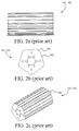
- the roller systems 101, 102 shown in figure 1 comprise multiple of straight and parallel outwardly protruding structures 201 with a kind of a depression 202 there between.
- the roller systems are arranged at a distance from the lower conveyor belt 108 such that when the outwardly protruding structures 201 point upwards as shown in figure 1b they press onto the lower conveyor belt creating an upwardly oriented force 110, 111 and thus a compression of the foodstuff when the foodstuff is positioned between the roller systems and the flattening plates.
- Figure 1 c depicts the scenario where the depression 202 is facing the lower conveyor belt 108 causing a release from the force/pressure state shown in figure 1b . Accordingly, this continuous pressure- release state provides a kind of a massage for the meat where the aim is to make the meat thin and/or larger and/or to provide a displacement of the fibres in the meat to make it more tender.
- the inventor of the present invention has appreciated that there is thus a need for an improved flattening apparatus that creates much less noise than the above mentioned apparatus such that the working conditions for an operator of the apparatus are greatly improved and has in consequence devised the present invention.
- the invention preferably seeks to mitigate, alleviate or eliminate one or more of the above mentioned disadvantages singly or in any combination.
- a roller system according to claim 1 comprising at least one outwardly protruding surface structure, said roller system being adapted to be used in relation to a flattening apparatus for flattening foodstuff, said flattening apparatus comprising:
- said at least one outwardly protruding surface structure is a single continuous structure designed in a spiral shaped way. This could e.g. be that the spiral turned one way around the roller system where the opposite ends of the spiral are in line with an axis parallel to the longitudinal axis of said roller system, or the spiral might just as well be turned two or more ways around the roller.
- said at least one outwardly protruding surface structure includes two or more separate outwardly protruding surface structures each of which having a first end and a second end, the internal arrangement between adjacent outwardly protruding surface structures being such that a first or a second end of a outwardly protruding surface structure is, in relation to an axis parallel to the longitudinal axis of said roller system, at least in line with a first or a second end of an adjacent outwardly protruding surface structure.
- each of said two or more separate outwardly protruding surface structures extend between the opposite ends of said roller system in a parallel way.
- said two or more separate outwardly protruding surface structures extend from the opposite ends of said roller system towards the mid-section of said roller system such that, for adjacent outwardly protruding surface structures, a first or a second end of an outwardly protruding surface structure extending from one end of the roller system towards said mid-section is at least in line with a first or a second end of an adjacent outwardly protruding surface structure extending from said mid-section to the opposite end of said roller system.
- said roller system is formed by two or more sub-roller systems each of which comprises a portion of said at least one outwardly protruding surface structure, the two or more sub-roller systems comprising mounting means for mounting the sub-roller systems together so as to form said roller system.
- a flattening apparatus for flattening foodstuff, said flattening apparatus comprising:
- said impact resistant system comprises:
- said impact resistance means is a flat plate structure.
- said impact resistance means is one or more of said roller system, e.g. one or more rollers or the like arranged with at least one outwardly protruding surface structure. These roller systems would preferably, but not necessarily, rotate in the same direction as a driving wheel that operates the driving of the second conveyor.
- the peripheral speed of said at least one roller system is larger than the speed of said first and/or second conveyor belts. In that way, it is ensured that while conveying the foodstuff through said flattening area it is ensured that sufficiently many "impact" points/areas on the foodstuff is achieved so as to reach the tenderness of the foodstuff.
- This may also be adapted to the type of foodstuff since one type of foodstuff may be more sensitive to such "impact" areas than other types of foodstuff.
- said at least one roller system include two roller systems arranged parallel to each other, and where the outwardly protruding surface structure of the two roller systems have opposite twist orientations. It is namely so that during the flattening process a sideward displacement of the food stuff may occur. Therefore, by utilizing two such roller systems the sideward displacement will be leveled out because the foodstuff will more or less move back to the sideward position of where it started.
- a roller system assembly comprising at least a first and a second sub-roller system each of which comprising at least one outwardly protruding surface structure, said at least first and second sub-roller systems comprising mounting means for mounting said sub-roller systems internally together in a fixed position in relation to each other so as to form said roller system.
- a method according to claim 16 is provided for flattening foodstuff using said flattening apparatus.
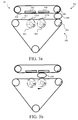
- FIG. 3 shows one embodiment of a flattening apparatus 300 according to the present invention for flattening foodstuff 309, where the foodstuff may include, but is not limited to, any types of meat such as beef, lamb, pork, or any type of poultry meat such as chicken or turkey breast, or a fish fillets of any types.
- the foodstuff may include, but is not limited to, any types of meat such as beef, lamb, pork, or any type of poultry meat such as chicken or turkey breast, or a fish fillets of any types.
- the flattening apparatus 300 comprises an impact resistance system 301, a first conveying means 302 and at least one roller system 303, 304 including at least one outwardly protruding structure that will be discussed in more details later.
- the first conveying means 302 should not be construed as being limited to the triangular shaped conveying means as shown here, but may just as well be "parallel arranged" similar as depicted in figure 1 .
- the at least one roller system 303, 304 may each comprise one or more rollers or the like.
- the impact resistance system 301 is a second conveying means 301 including a second conveyor belt 310 that is arranged opposite to a first conveyor belt 311 of the second conveyor means 301 and where impact resistance means, in this case two flat plate structures 307, 308, are arranged within the same plane opposite to two roller systems 303, 304, respectively, distally away from the first conveyor belt 311.
- driving shafts of the respective first and second conveyor systems are moving in opposite directions as indicated by arrows 305, 306 resulting in that that adjacent parts of the first and the second conveyor belts 310, 311 are moving in the same direction.
- the two roller systems 303, 304 are rotatable mounted to e.g. driving shafts and positioned side by side within the same plane distally away from the flat plate structures 307, 308 and rotate with a rotational speed that is preferably larger than the rotational speed of the driving shaft of the first conveying means.
- this embodiment shows two roller systems, the roller systems may just as well be a single roller system or three or more roller systems.
- the conveying speed of the first and the second belts which preferably run with substantially the same speed, may be between 0.06-0.4m/s, e.g. around 0.24m/s, and the rotational speed of the roller systems 303, 304 when the largest diameter of the roller systems is 200mm (including the outwardly protruding structures) may as an example be 70-178rot./min..
- the roller systems 303, 304 in this embodiment rotate in the same rotational direction as the driving shaft of the first conveying system, the roller systems may just as well rotate in the opposite direction.
- the two roller systems 303, 304 are placed across the first conveyor belt 311 and comprise at least one outwardly protruding surface structure that are askew in relation to the longitudinal axis of the roller system and designed such that at least a portion of the at least one outwardly protruding surface structure is in contact with the first conveyor belt at all times during rotation of the roller systems 303, 304.
- This continuous contact with the first conveyor belt 311 create, seen from this side view, two uphill portions 312a,b that during movement of the roller systems 303, 304 move continuously across the first conveyor belt 311 such that a contact between the roller systems 303, 304 and the first conveyor belt is maintained at all times.
- the result of conveying the foodstuff 309 through the flattening area results in that it is flattened which may make it thinner and/or larger and/or to displace the fibres in the meat and partially "fixating" them, which makes the meat more tender and makes a better "bite feeling".
- the foodstuff may be flattened in a manner, which is more gentle as compared to the prior art flattening apparatus, thereby resulting in products having an improved quality.
- the flattening process of the foodstuff should not be considered as being limited to the "two step" flattening process shown here where two roller systems 303, 304 are used, but the flattening process may just as well be a "single step” flattening processing or three or more steps flattening process with three or more roller systems (not shown here).
- the distance between the roller systems 303, 304 and the opposite flat plate structures 307, 308 may be different preferably such that distances decrease along the conveying direction which is preferred when food products such as schnitzel is to be flattened out, because such a flattening process can be very difficult in a single flattening process (where only one roller system is present).
- the roller systems 303, 304 may e.g.
- the roller system 303 may simply be adjusted upwards compared to the roller system 304, e.g. by adjusting the roller system 303 towards the flat plate structure 307.
- the flat plate structure 307 may be adjusted towards the roller system 303.
- the flattening process is a three step flattening process
- the first distance between the first roller system and the opposite flat plate structure may be 100mm
- the distance between the next roller system and the opposite flat plate structure may be 60mm
- the third distance between a third roller system and the opposite flat plate structure may be 45mm.
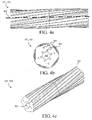
- Figure 4a-c depict a side view, a front view and a perspective view of one embodiment of a roller system 303, 304 according to the present invention, where the at least one outwardly protruding surface structure 401 includes more than one, in this case five, outwardly protruding surface structures extending between the opposite ends of said roller system in a parallel way such that, as shown in figure 4b the periphery is substantially circular.
- the internal arrangement between adjacent outwardly protruding surface structures is such that a first end of an outwardly protruding surface structure is, in relation to an axis parallel to the longitudinal axis 602 of said roller system, at least in line with a first or a second end of an adjacent outwardly protruding surface structure. In that way, as discussed in relation to figure 3 , it is ensured that at least a portion of the outwardly protruding surface structures 401 is in contact with said first conveyor belt at all times.
- the outwardly protruding surface structures 401 are an integral part of the roller system. These outwardly protruding surface structures 401 may just as well be mounted to the surface of a cylinder in a removable manner such that they may be replaced with new outwardly protruding surface structures, or the number of the outwardly protruding surface structures may be adjusted and adapted to the type of foodstuff that is to be flattened. In that way, the number may e.g. be reduced from five to four or less, or be made more than five, e.g. six or seven.
- the angle of the surface structures in relation to the longitudinal axis of the roller system 300 may then also be adjusted so that the above mentioned requirement, namely that the adjacent surface structures are in line with an axis parallel to the longitudinal axis of the roller system 300 is fulfilled.
- the embodiment shown here shows a center hole 405 and the holes 403 closest to the center hole 405 are implemented for mounting the roller system 303, 304 to a mounting shaft (see figure 5 ) that is preferably operable connected to a driving unit (see figure 5 ) that operates the rotational movement of the roller system.
- the four holes 404 closest to the periphery of the roller system 303, 304 are utilized for rigidly mounting sub-roller systems together so as to form said roller system.
- the roller system may be a roller system assembly consisting of two or more roller systems such that, when mounted together, form the above mentioned roller system 303, 304.
- Figure 5 shows an example of such a roller system assembly 500 consisting of two sub-roller systems 501, 502 that are mounted together as discussed in relation to figure 4 and a driving shaft 504, where the roller system is driven by a driving unit 503 that operates the rotational speed of the roller system as well as the direction of the rotation of the roller system.
- Figure 6 shows the embodiment from figure 4 where the surface structure has, for further clarification, been flattened out, showing where two adjacent outwardly protruding surface structures 401 a,b are arranged in a parallel way and designed such that they are in line with an axis 601 being parallel to the longitudinal axis 602 of the roller system.
- the arrow indicates an example of a rotational direction of the roller system.
- Figure 7 shows another example of an outwardly protruding structure arrangement where several outwardly protruding surface structures extend from the opposite ends of said roller system 700 towards the mid-section of the roller system such that, for adjacent outwardly protruding surface structures 701, 702, a first or a second end of an outwardly protruding surface structures extending from one end of the roller system towards said mid-section is at least in line in relation to an axis 704a,b parallel to the longitudinal axis of the roller system 703 with a first or a second end of an adjacent outwardly protruding surface structure extending from said mid-section to the opposite end of said roller system.
- the left side and the right side of the outwardly protruding surface structures are parallel, respectively.
- the outwardly protruding surface structures may further include small wheels so as to reduce the friction between the roller systems and the first conveyor belt, or the outwardly protruding structures may more or less be made of such outwardly protruding wheels.
- the at least one outwardly protruding surface structure may include a single continuous structure designed in a spiral shaped way.
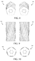
- Figures 8-10 show a perspective view, a top view and a front view of one embodiment of the roller system arrangement depicted in figure 3 , where the two roller systems are arranged parallel to each other, and where the outwardly protruding surface structure designed in said spiral shaped way have opposite twist orientations.
- the foodstuff may namely undergo sideward movement after passing the first roller system due to the spiral shaped arrangement, but by utilizing the second roller system with the opposite twist orientation the foodstuff will more or less move back to the sideward position of where it started. It is accordingly prevented that the foodstuff falls sideways from the conveyor belt 311.
- the impact resistance means of the impact resistant system may be one or more of said roller system, e.g.
- a roller which may comprise the at least one outwardly protruding surface structure.
- such an impact resistance roller may have an opposite twist orientation as compared to the roller system arranged correspondingly below e.g. the first conveyor belt 311, cf. e.g. figure 3 .
- the advantages as discussed above is also achieved, e.g. the prevention of sideways movement.
Landscapes
- Engineering & Computer Science (AREA)
- Life Sciences & Earth Sciences (AREA)
- Wood Science & Technology (AREA)
- Zoology (AREA)
- Food Science & Technology (AREA)
- Mechanical Engineering (AREA)
- Meat, Egg Or Seafood Products (AREA)
- Formation And Processing Of Food Products (AREA)
Description
- The present invention relates to a roller system and roller system assembly comprising at least one outwardly protruding surface structure adapted to be used in relation to a flattening apparatus for flattening foodstuff. Moreover, the invention relates to a flattening apparatus comprising such a roller system.
- It has always been known that pieces of meat are flattened, in particular if they are to be processed in schnitzel form. On the one hand, this flattening operation is carried out with the aim of increasing the size of the pieces of meat while simultaneously reducing the thickness. In addition, the flattening operation causes the meat to become tender. Connective tissue is known to make meat tough. The flattening operation causes the fibrils to be rearranged and the connective tissue between the fibrils to tear. Devices such as disclosed in
US6672202 andEP1542540 which, in a manner comparable to the conventional operation of beating the meat, are intended to make it possible for the pieces of meat to be flattened. -
Figure 1 shows graphically such aflattening apparatus 100 forflattening foodstuff 112 such as meat where tworoller systems lower conveyor belt 108 and where opposite to the two roller systems are rigidly mountedflattening plate structures upper conveyor belt 107 distally away from theroller systems foodstuff 112 is performed by means of conveying the foodstuff via the upper and lower conveyor belts that run in the same direction, while simultaneously rotating theroller systems figure 2 theroller systems figure 1 comprise multiple of straight and parallel outwardly protrudingstructures 201 with a kind of adepression 202 there between. The roller systems are arranged at a distance from thelower conveyor belt 108 such that when the outwardly protrudingstructures 201 point upwards as shown infigure 1b they press onto the lower conveyor belt creating an upwardly orientedforce 110, 111 and thus a compression of the foodstuff when the foodstuff is positioned between the roller systems and the flattening plates.Figure 1 c depicts the scenario where thedepression 202 is facing thelower conveyor belt 108 causing a release from the force/pressure state shown infigure 1b . Accordingly, this continuous pressure- release state provides a kind of a massage for the meat where the aim is to make the meat thin and/or larger and/or to provide a displacement of the fibres in the meat to make it more tender. - The disadvantage with this apparatus is however that the apparatus is noisy during the flattening, where the position shown in
figure 1b where the outwardly protrudingsurface structure 201 hits thelower conveyor belt 108 and thus the meat simultaneously, creates loud hammering sound. Even when no foodstuff is present the impact from the outwardly protrudingsurface structure 201 and thelower conveyor belt 108 creates a noise that can be very irritating for an operator of the apparatus. - The inventor of the present invention has appreciated that there is thus a need for an improved flattening apparatus that creates much less noise than the above mentioned apparatus such that the working conditions for an operator of the apparatus are greatly improved and has in consequence devised the present invention.
- It would be advantageous to achieve an improved flattening apparatus that is capable of flattening foodstuff where the noise reduction is such that the working conditions for an operator of the apparatus are greatly improved. In general, the invention preferably seeks to mitigate, alleviate or eliminate one or more of the above mentioned disadvantages singly or in any combination. In particular, it may be seen as an object of the present invention to provide a roller system and a roller system assembly that is adapted to be used in such a flattening apparatus that solves the above mentioned problems, or other problems, of the prior art.
- To better address one or more of these concerns, in a first aspect of the invention a roller system according to claim 1 is provided comprising at least one outwardly protruding surface structure, said
roller system being adapted to be used in relation to a flattening apparatus for flattening foodstuff, said flattening apparatus comprising: - an impact resistant system, and
- a first conveying means including a first conveyor belt, said first conveying means being arranged opposite to said impact resistant system with the first conveyor belt facing said impact resistant system, the area between the first conveyor belt and the impact resistant system defining a flattening area,
- In one embodiment, said at least one outwardly protruding surface structure is a single continuous structure designed in a spiral shaped way. This could e.g. be that the spiral turned one way around the roller system where the opposite ends of the spiral are in line with an axis parallel to the longitudinal axis of said roller system, or the spiral might just as well be turned two or more ways around the roller.
- In one embodiment, said at least one outwardly protruding surface structure includes two or more separate outwardly protruding surface structures each of which having a first end and a second end, the internal arrangement between adjacent outwardly protruding surface structures being such that a first or a second end of a outwardly protruding surface structure is, in relation to an axis parallel to the longitudinal axis of said roller system, at least in line with a first or a second end of an adjacent outwardly protruding surface structure. In an embodiment, each of said two or more separate outwardly protruding surface structures extend between the opposite ends of said roller system in a parallel way. In another embodiment, said two or more separate outwardly protruding surface structures extend from the opposite ends of said roller system towards the mid-section of said roller system such that, for adjacent outwardly protruding surface structures, a first or a second end of an outwardly protruding surface structure extending from one end of the roller system towards said mid-section is at least in line with a first or a second end of an adjacent outwardly protruding surface structure extending from said mid-section to the opposite end of said roller system.
- In one embodiment, said roller system is formed by two or more sub-roller systems each of which comprises a portion of said at least one outwardly protruding surface structure, the two or more sub-roller systems comprising mounting means for mounting the sub-roller systems together so as to form said roller system. Accordingly, an advantageous solution is provided to divide the roller system, especially if the roller system is relatively long, into smaller items for e.g. facilitate the transport of the roller, or e.g. if a part of the roller becomes damaged that only a part of the roller system needs to be replaced.
- According to a second aspect of the invention a flattening apparatus according to claim 7 is provided for
flattening foodstuff, said flattening apparatus comprising: - an impact resistant system,
- a first conveying means including a first conveyor belt, said first conveying means being arranged opposite to said impact resistant system with the first conveyor belt facing said impact resistant system, the area between the first conveyor belt and the impact resistant system defining a flattening area, and
- at least one roller system comprising at least one outwardly protruding surface structure , said at least one roller system being rotatable mounted adjacent to said first conveyor belt distally away from said impact resistant system across the first conveyor belt, said flattening of the foodstuff including rotating said at least one roller system while conveying the foodstuff through said flattening area such that said at least one outwardly protruding surface structure presses said first conveyor belt towards said impact resistant system causing a compression of the foodstuff,
- In one embodiment, said impact resistant system comprises:
- a second conveying means including a second conveyor belt arrange opposited to said first conveying means in a way such that adjacent sides of the first and the second conveyor belts are facing each other and during flattening are moving in the same direction, and
- an impact resistance means arranged adjacent to said second conveyor belt distally away from said first conveyor belt.
- In one embodiment, said impact resistance means is a flat plate structure. In another embodiment, said impact resistance means is one or more of said roller system, e.g. one or more rollers or the like arranged with at least one outwardly protruding surface structure. These roller systems would preferably, but not necessarily, rotate in the same direction as a driving wheel that operates the driving of the second conveyor.
- In one embodiment, during flattening the peripheral speed of said at least one roller system is larger than the speed of said first and/or second conveyor belts. In that way, it is ensured that while conveying the foodstuff through said flattening area it is ensured that sufficiently many "impact" points/areas on the foodstuff is achieved so as to reach the tenderness of the foodstuff. This may also be adapted to the type of foodstuff since one type of foodstuff may be more sensitive to such "impact" areas than other types of foodstuff.
- In one embodiment, said at least one roller system include two roller systems arranged parallel to each other, and where the outwardly protruding surface structure of the two roller systems have opposite twist orientations. It is namely so that during the flattening process a sideward displacement of the food stuff may occur. Therefore, by utilizing two such roller systems the sideward displacement will be leveled out because the foodstuff will more or less move back to the sideward position of where it started.
- According to a third aspect of the invention a roller system assembly according to claim 15 is provided comprising at least a first and a second sub-roller system each of which comprising at least one outwardly protruding surface structure, said at least first and second sub-roller systems comprising mounting means for mounting said sub-roller systems internally together in a fixed position in relation to each other so as to form said roller system.
- According to a fourth aspect, a method according to claim 16 is provided for flattening foodstuff using said flattening apparatus.
- In general the various aspects of the invention may be combined and coupled in any way possible within the scope of the invention. These and other aspects, features and/or advantages of the invention will be apparent from and elucidated with reference to the embodiments described hereinafter.
- Embodiments of the invention will be described, by way of example only, with reference to the drawings, in which
-
figures 1 shows a prior art flattening apparatus for flattening foodstuff, -
figure 2 shows a roller system implemented in the prior art flattening apparatur shown infigure 1 , -
figure 3a,b shows one embodiment of flattening apparatus according to the present invention for flattening foodstuff, -
figure 4a-c depict a side view, a front view and a perspective view of one embodiment of a roller system according to the present invention, -
figure 5 shows an example of such a roller system assembly consisting of two sub-roller systems that are mounted together as discussed in relation tofigure 4 and a driving shaft coupled to a driving unit, -
figure 6 shows the embodiment fromfigure 4 where the surface structure has been flattened out, -
figure 7 shows another example of an outwardly protruding structure arrangement where several outwardly protruding surface structures extend from the opposite ends of said roller system towards the mid-section of the roller system, and -
figures 8-10 show one embodiment of a flattening apparatus according to the present invention where two roller systems arranged parallel to each other are utilized. -
Figure 3 shows one embodiment of aflattening apparatus 300 according to the present invention for flatteningfoodstuff 309, where the foodstuff may include, but is not limited to, any types of meat such as beef, lamb, pork, or any type of poultry meat such as chicken or turkey breast, or a fish fillets of any types. - The flattening
apparatus 300 comprises animpact resistance system 301, a first conveyingmeans 302 and at least oneroller system figure 1 . The at least oneroller system - In the embodiment depicted here the
impact resistance system 301 is a second conveying means 301 including asecond conveyor belt 310 that is arranged opposite to afirst conveyor belt 311 of the second conveyor means 301 and where impact resistance means, in this case twoflat plate structures roller systems first conveyor belt 311. - When flattening the
foodstuff 309 driving shafts of the respective first and second conveyor systems are moving in opposite directions as indicated byarrows second conveyor belts roller systems flat plate structures - As an example, the conveying speed of the first and the second belts, which preferably run with substantially the same speed, may be between 0.06-0.4m/s, e.g. around 0.24m/s, and the rotational speed of the
roller systems roller systems - The two
roller systems first conveyor belt 311 and comprise at least one outwardly protruding surface structure that are askew in relation to the longitudinal axis of the roller system and designed such that at least a portion of the at least one outwardly protruding surface structure is in contact with the first conveyor belt at all times during rotation of theroller systems first conveyor belt 311 create, seen from this side view, twouphill portions 312a,b that during movement of theroller systems first conveyor belt 311 such that a contact between theroller systems figure 3b . This continuous contact results in enormous noise reduction compared to the prior art flattening apparatus shown infigure 1 that gives a lot of "flapping" noise from the belt and also "hammering" forces which results in that the apparatus infigure 1 becomes very noise. The design/arrangement of the outwardly protruding surface structure of the roller system in the embodiment shown infigure 3 reduces however, or even eliminates these "hammering" forces since at least a portion of the outwardly protruding surface structure is in contact with thefirst conveyor belt 311 at all times. Furthermore, this design/arrangement has the additional advantage that the machinery, e.g. bearings, drive means, etc. of the apparatus is subjected to less wear than is the case with the prior art flattening apparatus, e.g. due to the reduction or even elimination of the these "hammering" forces. - If the foodstuff is as an example meat, the result of conveying the
foodstuff 309 through the flattening area results in that it is flattened which may make it thinner and/or larger and/or to displace the fibres in the meat and partially "fixating" them, which makes the meat more tender and makes a better "bite feeling". Furthermore, by the roller system and the flattening apparatus according to the invention, the foodstuff may be flattened in a manner, which is more gentle as compared to the prior art flattening apparatus, thereby resulting in products having an improved quality. - The flattening process of the foodstuff should not be considered as being limited to the "two step" flattening process shown here where two
roller systems roller systems flat plate structures roller systems roller system 303 that is positioned on the downstream side compared toroller system 304 may have larger diameter, or theroller system 303 may simply be adjusted upwards compared to theroller system 304, e.g. by adjusting theroller system 303 towards theflat plate structure 307. Alternatively, theflat plate structure 307 may be adjusted towards theroller system 303. As an example, if the flattening process is a three step flattening process, the first distance between the first roller system and the opposite flat plate structure may be 100mm, the distance between the next roller system and the opposite flat plate structure may be 60mm and the third distance between a third roller system and the opposite flat plate structure may be 45mm. -
Figure 4a-c depict a side view, a front view and a perspective view of one embodiment of aroller system surface structure 401 includes more than one, in this case five, outwardly protruding surface structures extending between the opposite ends of said roller system in a parallel way such that, as shown infigure 4b the periphery is substantially circular. Moreover; the internal arrangement between adjacent outwardly protruding surface structures is such that a first end of an outwardly protruding surface structure is, in relation to an axis parallel to thelongitudinal axis 602 of said roller system, at least in line with a first or a second end of an adjacent outwardly protruding surface structure. In that way, as discussed in relation tofigure 3 , it is ensured that at least a portion of the outwardly protrudingsurface structures 401 is in contact with said first conveyor belt at all times. - As shown in this embodiment, the outwardly protruding
surface structures 401 are an integral part of the roller system. These outwardly protrudingsurface structures 401 may just as well be mounted to the surface of a cylinder in a removable manner such that they may be replaced with new outwardly protruding surface structures, or the number of the outwardly protruding surface structures may be adjusted and adapted to the type of foodstuff that is to be flattened. In that way, the number may e.g. be reduced from five to four or less, or be made more than five, e.g. six or seven. The angle of the surface structures in relation to the longitudinal axis of theroller system 300 may then also be adjusted so that the above mentioned requirement, namely that the adjacent surface structures are in line with an axis parallel to the longitudinal axis of theroller system 300 is fulfilled. - The embodiment shown here shows a
center hole 405 and theholes 403 closest to thecenter hole 405 are implemented for mounting theroller system figure 5 ) that is preferably operable connected to a driving unit (seefigure 5 ) that operates the rotational movement of the roller system. The fourholes 404 closest to the periphery of theroller system roller system -
Figure 5 shows an example of such aroller system assembly 500 consisting of twosub-roller systems figure 4 and a drivingshaft 504, where the roller system is driven by adriving unit 503 that operates the rotational speed of the roller system as well as the direction of the rotation of the roller system. -
Figure 6 shows the embodiment fromfigure 4 where the surface structure has, for further clarification, been flattened out, showing where two adjacent outwardly protrudingsurface structures 401 a,b are arranged in a parallel way and designed such that they are in line with anaxis 601 being parallel to thelongitudinal axis 602 of the roller system. The arrow indicates an example of a rotational direction of the roller system. -
Figure 7 shows another example of an outwardly protruding structure arrangement where several outwardly protruding surface structures extend from the opposite ends of saidroller system 700 towards the mid-section of the roller system such that, for adjacent outwardly protrudingsurface structures axis 704a,b parallel to the longitudinal axis of theroller system 703 with a first or a second end of an adjacent outwardly protruding surface structure extending from said mid-section to the opposite end of said roller system. Or put in other words, the left side and the right side of the outwardly protruding surface structures are parallel, respectively. - It should be noted that several different arrangements of such outwardly protruding surface structures are possible, where the arrangements are such that the roller system maintains a contact with said first conveyor belt at all times.
- The outwardly protruding surface structures may further include small wheels so as to reduce the friction between the roller systems and the first conveyor belt, or the outwardly protruding structures may more or less be made of such outwardly protruding wheels.
- Also, in an embodiment the at least one outwardly protruding surface structure may include a single continuous structure designed in a spiral shaped way.
-
Figures 8-10 show a perspective view, a top view and a front view of one embodiment of the roller system arrangement depicted infigure 3 , where the two roller systems are arranged parallel to each other, and where the outwardly protruding surface structure designed in said spiral shaped way have opposite twist orientations. The foodstuff may namely undergo sideward movement after passing the first roller system due to the spiral shaped arrangement, but by utilizing the second roller system with the opposite twist orientation the foodstuff will more or less move back to the sideward position of where it started. It is accordingly prevented that the foodstuff falls sideways from theconveyor belt 311. As discussed previously, the impact resistance means of the impact resistant system may be one or more of said roller system, e.g. a roller, which may comprise the at least one outwardly protruding surface structure. In the embodiment shown infigures 8-10 such an impact resistance roller may have an opposite twist orientation as compared to the roller system arranged correspondingly below e.g. thefirst conveyor belt 311, cf. e.g.figure 3 . Hereby the advantages as discussed above is also achieved, e.g. the prevention of sideways movement. - While the invention has been illustrated and described in detail in the drawings and foregoing description, such illustration and description are to be considered illustrative or exemplary and not restrictive; the invention is not limited to the disclosed embodiments, since its scope is only limited by the appended claims. Other variations to the disclosed embodiments can be understood and effected by those skilled in the art in practicing the claimed invention, from a study of the drawings, the disclosure, and the appended claims. In the claims, the word "comprising" does not exclude other elements or steps, and the indefinite article "a" or "an" does not exclude a plurality. The mere fact that certain measures are recited in mutually different dependent claims does not indicate that a combination of these measures cannot be used to advantage.
wherein said at least one outwardly protruding surface structure is askew in relation to the longitudinal axis of the roller system and is designed such that at least a portion of the at least one outwardly protruding surface structure is in contact with the first conveyor belt substantially at all times during rotation of said roller system. Accordingly, the fact the contact between a part of the at least one outwardly protruding surface structure is always present means the sound that would otherwise be formed upon coming into contact with the first conveyor belt and fully releasing the contact with the first conveyor belt, i.e. a way of an "on/off mode" is eliminated. Moreover, the hammering sound formed when the foodstuff is hammered towards the impact resistant system when using a prior art roller, where the outwardly protruding surface structures extend between the opposite end of the roller parallel to the longitudinal axis of the roller, is no longer present. The roller system may comprise one or more rollers or the like, wherein at least one of said one or more rollers may comprise said at least one outwardly protruding surface structure.
Claims (16)
- A roller system (303, 304) comprising at least one outwardly protruding surface structure (401), said roller system being adapted to be used in relation to a flattening apparatus (300) for flattening foodstuff (309), said flattening apparatus comprising:• an impact resistant system (301), and• a first conveying means (302) including a first conveyor belt (311), said first conveying means being arranged opposite to said impact resistant system with the first conveyor belt facing said impact resistant system, the area between the first conveyor belt and the impact resistant system defining a flattening area,said roller system being adapted to be rotatable mounted adjacent to said first conveyor belt distally away from said impact resistant system across the first conveyor belt, said flattening of the foodstuff including rotating said roller system while conveying the foodstuff through said flattening area such that said at least one outwardly protruding surface structure is askew in relation to the longitudinal axis (602) of the roller system and presses
said first conveyor belt towards said impact resistant system causing a compression of the foodstuff,
characterized in that said at least one outwardly protruding surface structure is designed such that at least a portion of the at least one outwardly protruding surface structure is in contact with the first conveyor belt substantially at all times during rotation of roller system. - A roller system according to claim 1, wherein said at least one outwardly protruding surface structure is a single continuous structure designed in a spiral shaped way.
- A roller system according to claim 1, wherein said at least one outwardly protruding surface structure includes two or more separate outwardly protruding surface structures (401a,b) each of which having a first end and a second end, the internal arrangement between adjacent outwardly protruding surface structures being such that a first or a second end of a outwardly protruding surface structure is, in relation to an axis (601) parallel to the longitudinal axis of said roller system (602), at least in line with a first or a second end of an adjacent outwardly protruding surface structure.
- A roller system according to claim 3, wherein each of said two or more separate outwardly protruding surface structures extend between the opposite ends of said roller system in a parallel way.
- A roller system according to claim 3, wherein said two or more separate outwardly protruding surface structures (701, 702) extend from the opposite ends of said roller system towards the mid-section of said roller system such that, for adjacent outwardly protruding surface structures, a first or a second end of an outwardly protruding surface structure extending from one end of the roller system towards said mid-section is, in relation to an axis (704a,b) parallel to the longitudinal axis of said roller system (703), at least in line with a first or a second end of an adjacent outwardly protruding surface structure extending from said mid-section to the opposite end of said roller system.
- A roller system according to any of the preceding claims, where said roller system is formed by two or more sub-roller systems (501, 502) each of which comprises a portion of said at least one outwardly protruding surface structure, the two or more sub-roller systems comprising mounting means for mounting the sub-roller systems together so as to form said roller system.
- A flattening apparatus (300) for flattening foodstuff, said flattening apparatus comprising:• an impact resistant system (301),• a first conveying means (302) including a first conveyor belt (311) and, said first conveying means being arranged opposite to said impact resistant system with the first conveyor belt facing said impact resistant system, the area between the first conveyor belt and the impact resistant system defining a flattening area, and• at least one roller system (303, 304) comprising at least one outwardly protruding surface structure (401), said at least one roller system being rotatable mounted adjacent to said first conveyor belt distally away from said impact resistant system across the first conveyor belt, said flattening of the foodstuff including rotating said at least one roller system while conveying the foodstuff through said flattening area such that said at least one outwardly protruding surface structure is askew in relation to the longitudinal axis (602) of said at least one roller system and presses said first conveyor belt towards said impact resistant system causing a compression of the foodstuff,characterized in that said at least one outwardly protruding surface structure is designed such that at least a portion of the at least one outwardly protruding surface structure is in contact with the first conveyor belt substantially at all times during rotation of said at least one roller system.
- A flattening apparatus according to claim 7, wherein said at least one outwardly protruding surface structure is a single continuous structure designed in a spiral shaped way.
- A flattening apparatus according to claim 7, wherein said at least one outwardly protruding surface structure includes two or more separate outwardly protruding surface structures each of which having a first end and a second end, the internal arrangement between adjacent outwardly protruding surface structures being such that a first or a second end of an outwardly protruding surface structure is, in relation to an axis parallel to the longitudinal axis of said at least one roller system, at least in line with a first or a second end of an adjacent outwardly protruding surface structure.
- A flattening apparatus according to claim 9, wherein each of said two or more separate outwardly protruding surface structures extend between the opposite ends of said at least one roller system in a parallel way.
- A flattening apparatus according to claim 9, wherein said two or more separate outwardly protruding surface structures extend from the opposite ends of said at least one roller system towards the mid-section of said roller system such that, for adjacent outwardly protruding surface structures, a first or a second end of an outwardly protruding surface structure extending from one end of said at least one roller system towards said mid-section is at least in line with a first or a second end of an adjacent outwardly protruding surface structure extending from said mid-section to the opposite end of said at least one roller system.
- A flattening apparatus according to any of the claims 7-11, wherein said impact resistant system comprises:• a second conveying means including a second conveyor belt arranged opposite to said first conveying means in a way such that adjacent sides of the first and the second conveyor belts are facing each other and during flattening are moving in the same direction, and• an impact resistance means arranged adjacent to said second conveyor belt distally away from said first conveyor belt, wherein e.g. said impact resistance means is a flat plate structure or said impact resistance means is one or more of said roller system.
- A flattening apparatus according to any of the claims 7-12, wherein during flattening the peripheral speed of said at least one roller system is larger than the speed of said first and/or second conveyor belts.
- A flattening apparatus according to any of the claims 8-13, wherein said at least one roller system (303, 304) includes two roller systems arranged parallel to each other, and where the outwardly protruding surface structure of the two roller systems have opposite twist orientations.
- A roller system assembly comprising at least a first and a second sub-roller system each of which comprising at least one outwardly protruding surface structure, characterized in said at least first and second sub-roller systems comprising mounting means for mounting said sub-roller systems internally together in a fixed position in relation to each other so as to form a roller system according to any of the claims 1-6.
- A method of flattening foodstuff (309) using a flattening apparatus according to any of the claims 7-14.
Priority Applications (1)
| Application Number | Priority Date | Filing Date | Title |
|---|---|---|---|
| EP13755942.3A EP2884846B1 (en) | 2012-08-17 | 2013-08-19 | A roller system adapted to be used in relation to a flattening apparatus for flattening foodstuff |
Applications Claiming Priority (5)
| Application Number | Priority Date | Filing Date | Title |
|---|---|---|---|
| US201261684208P | 2012-08-17 | 2012-08-17 | |
| EP12180873.7A EP2698065A1 (en) | 2012-08-17 | 2012-08-17 | A roller system adapted to be used in relation to a flattening apparatus for flattening foodstuff |
| DKPA201270737 | 2012-11-28 | ||
| PCT/DK2013/000050 WO2014026690A1 (en) | 2012-08-17 | 2013-08-19 | A roller system adapted to be used in relation to a flattening apparatus for flattening foodstuff |
| EP13755942.3A EP2884846B1 (en) | 2012-08-17 | 2013-08-19 | A roller system adapted to be used in relation to a flattening apparatus for flattening foodstuff |
Publications (2)
| Publication Number | Publication Date |
|---|---|
| EP2884846A1 EP2884846A1 (en) | 2015-06-24 |
| EP2884846B1 true EP2884846B1 (en) | 2016-09-14 |
Family
ID=50101250
Family Applications (1)
| Application Number | Title | Priority Date | Filing Date |
|---|---|---|---|
| EP13755942.3A Active EP2884846B1 (en) | 2012-08-17 | 2013-08-19 | A roller system adapted to be used in relation to a flattening apparatus for flattening foodstuff |
Country Status (9)
| Country | Link |
|---|---|
| US (1) | US9770877B2 (en) |
| EP (1) | EP2884846B1 (en) |
| JP (1) | JP2015530878A (en) |
| CN (1) | CN104640452B (en) |
| CA (1) | CA2879556C (en) |
| DK (1) | DK2884846T3 (en) |
| ES (1) | ES2595048T3 (en) |
| PL (1) | PL2884846T3 (en) |
| WO (1) | WO2014026690A1 (en) |
Families Citing this family (2)
| Publication number | Priority date | Publication date | Assignee | Title |
|---|---|---|---|---|
| JP6867335B2 (en) * | 2018-07-02 | 2021-04-28 | 四国日清食品株式会社 | How to make sliced meat for frying |
| CN113951416A (en) * | 2021-11-17 | 2022-01-21 | 安徽燕之坊食品有限公司 | A kind of insecticidal and sterilization treatment method based on kidney bean product and prolonging its shelf life |
Family Cites Families (8)
| Publication number | Priority date | Publication date | Assignee | Title |
|---|---|---|---|---|
| US311199A (en) * | 1885-01-27 | Meat-tenderer | ||
| DE3538903C1 (en) | 1985-11-02 | 1987-01-29 | Schroeder Edmund Maschf | Apparatus for depositing curved pieces of dough |
| IT1298837B1 (en) | 1998-01-08 | 2000-02-07 | Rb Engineering S R L | PROCEDURE FOR THE KEEPING OF PIECES OF MEAT, MECHANICAL EQUIPMENT FOR CARRYING OUT THE PROCEDURE AND KEEPING MEAT |
| DE10017348C2 (en) | 2000-04-07 | 2003-04-24 | Thomas Voelkl | Device for flattening pieces of meat |
| EP1338203A1 (en) | 2002-02-25 | 2003-08-27 | Jozsef Palásti | Dough forming apparatus with a pressure roller for bakery products from a multi-layered dough material |
| DE10212881A1 (en) | 2002-03-22 | 2003-10-02 | Thomas Voelkl | Device for flattening food, in particular pieces of meat |
| USD550523S1 (en) | 2006-03-11 | 2007-09-11 | Stewart Anna M | Tenderizing device |
| US8579774B2 (en) * | 2009-07-09 | 2013-11-12 | Deere & Company | Drive roller for flat belts |
-
2013
- 2013-08-19 US US14/418,647 patent/US9770877B2/en active Active
- 2013-08-19 EP EP13755942.3A patent/EP2884846B1/en active Active
- 2013-08-19 CA CA2879556A patent/CA2879556C/en active Active
- 2013-08-19 JP JP2015526879A patent/JP2015530878A/en active Pending
- 2013-08-19 ES ES13755942.3T patent/ES2595048T3/en active Active
- 2013-08-19 WO PCT/DK2013/000050 patent/WO2014026690A1/en not_active Ceased
- 2013-08-19 PL PL13755942T patent/PL2884846T3/en unknown
- 2013-08-19 DK DK13755942.3T patent/DK2884846T3/en active
- 2013-08-19 CN CN201380043591.4A patent/CN104640452B/en active Active
Also Published As
| Publication number | Publication date |
|---|---|
| US20150174845A1 (en) | 2015-06-25 |
| DK2884846T3 (en) | 2017-01-09 |
| PL2884846T3 (en) | 2017-02-28 |
| JP2015530878A (en) | 2015-10-29 |
| EP2884846A1 (en) | 2015-06-24 |
| WO2014026690A1 (en) | 2014-02-20 |
| CN104640452A (en) | 2015-05-20 |
| CA2879556A1 (en) | 2014-02-20 |
| ES2595048T3 (en) | 2016-12-27 |
| CA2879556C (en) | 2020-10-27 |
| US9770877B2 (en) | 2017-09-26 |
| CN104640452B (en) | 2017-07-07 |
Similar Documents
| Publication | Publication Date | Title |
|---|---|---|
| JP6521998B2 (en) | Cutting machine and method for cutting food products into smaller food products | |
| EP3485735B1 (en) | Deskinning apparatus and method for deskinning a poultry leg or part of a poultry leg | |
| US9125424B2 (en) | Method for making a filleting cut for filleting fish, device for making the filleting cut according to the method, and circular knife pair and circular knife set up for the method and the device | |
| US9259011B2 (en) | Method and apparatus for shredding meat | |
| US9770877B2 (en) | Roller system adapted to be used in relation to a flattening apparatus for flattening foodstuff | |
| WO1999054098A1 (en) | Method ans apparatus for uniformly slicing food products | |
| EP2698065A1 (en) | A roller system adapted to be used in relation to a flattening apparatus for flattening foodstuff | |
| US6672202B2 (en) | Device for flattening pieces of meat | |
| EP3224006B1 (en) | A cutting device adapted to be placed above a gap extending across a carrying surface of a conveyor system and a corresponding method for cutting food items. | |
| EP2796046B1 (en) | Meat mass processing machine | |
| EP2921055A1 (en) | Method, processing device and processing line for mechanically processing an organ or organs taken out from slaughtered poultry | |
| EP2921056A1 (en) | Method, processing device and processing line for mechanically processing an organ or organs taken out from slaughtered poultry | |
| EP2921054A1 (en) | Method, processing device and processing line for mechanically processing an organ or organs taken out from slaughtered poultry | |
| US9661860B2 (en) | Meatball rolling machine | |
| JP5473401B2 (en) | Eating machine for poultry carcass | |
| US4437208A (en) | Meat tenderizer | |
| US20100084497A1 (en) | Grating for mincer | |
| IE45551B1 (en) | Meat tenderising apparatus | |
| KR101938970B1 (en) | Crab Shells Removal Apparatus Having Improved Sorting Quality | |
| CN215684537U (en) | A tenderizer for meat food processing | |
| US20240025071A1 (en) | Food cutter and method of cutting food | |
| US20070057100A1 (en) | Forged blade for bale processing machines | |
| WO2018145131A8 (en) | Cross cut tenderizer | |
| RU2024115123A (en) | MACHINE KNIFE | |
| IE20160044A1 (en) | Removing meat from a shell |
Legal Events
| Date | Code | Title | Description |
|---|---|---|---|
| PUAI | Public reference made under article 153(3) epc to a published international application that has entered the european phase |
Free format text: ORIGINAL CODE: 0009012 |
|
| 17P | Request for examination filed |
Effective date: 20150304 |
|
| AK | Designated contracting states |
Kind code of ref document: A1 Designated state(s): AL AT BE BG CH CY CZ DE DK EE ES FI FR GB GR HR HU IE IS IT LI LT LU LV MC MK MT NL NO PL PT RO RS SE SI SK SM TR |
|
| AX | Request for extension of the european patent |
Extension state: BA ME |
|
| DAX | Request for extension of the european patent (deleted) | ||
| GRAP | Despatch of communication of intention to grant a patent |
Free format text: ORIGINAL CODE: EPIDOSNIGR1 |
|
| INTG | Intention to grant announced |
Effective date: 20160318 |
|
| RAP1 | Party data changed (applicant data changed or rights of an application transferred) |
Owner name: MAREL A/S |
|
| RIC1 | Information provided on ipc code assigned before grant |
Ipc: A22C 9/00 20060101AFI20160304BHEP |
|
| GRAS | Grant fee paid |
Free format text: ORIGINAL CODE: EPIDOSNIGR3 |
|
| GRAA | (expected) grant |
Free format text: ORIGINAL CODE: 0009210 |
|
| AK | Designated contracting states |
Kind code of ref document: B1 Designated state(s): AL AT BE BG CH CY CZ DE DK EE ES FI FR GB GR HR HU IE IS IT LI LT LU LV MC MK MT NL NO PL PT RO RS SE SI SK SM TR |
|
| REG | Reference to a national code |
Ref country code: GB Ref legal event code: FG4D |
|
| REG | Reference to a national code |
Ref country code: CH Ref legal event code: EP |
|
| REG | Reference to a national code |
Ref country code: IE Ref legal event code: FG4D Ref country code: NL Ref legal event code: FP |
|
| REG | Reference to a national code |
Ref country code: AT Ref legal event code: REF Ref document number: 827895 Country of ref document: AT Kind code of ref document: T Effective date: 20161015 |
|
| REG | Reference to a national code |
Ref country code: DE Ref legal event code: R096 Ref document number: 602013011648 Country of ref document: DE |
|
| REG | Reference to a national code |
Ref country code: ES Ref legal event code: FG2A Ref document number: 2595048 Country of ref document: ES Kind code of ref document: T3 Effective date: 20161227 |
|
| REG | Reference to a national code |
Ref country code: DK Ref legal event code: T3 Effective date: 20170103 |
|
| REG | Reference to a national code |
Ref country code: LT Ref legal event code: MG4D |
|
| PG25 | Lapsed in a contracting state [announced via postgrant information from national office to epo] |
Ref country code: LT Free format text: LAPSE BECAUSE OF FAILURE TO SUBMIT A TRANSLATION OF THE DESCRIPTION OR TO PAY THE FEE WITHIN THE PRESCRIBED TIME-LIMIT Effective date: 20160914 Ref country code: FI Free format text: LAPSE BECAUSE OF FAILURE TO SUBMIT A TRANSLATION OF THE DESCRIPTION OR TO PAY THE FEE WITHIN THE PRESCRIBED TIME-LIMIT Effective date: 20160914 Ref country code: HR Free format text: LAPSE BECAUSE OF FAILURE TO SUBMIT A TRANSLATION OF THE DESCRIPTION OR TO PAY THE FEE WITHIN THE PRESCRIBED TIME-LIMIT Effective date: 20160914 Ref country code: RS Free format text: LAPSE BECAUSE OF FAILURE TO SUBMIT A TRANSLATION OF THE DESCRIPTION OR TO PAY THE FEE WITHIN THE PRESCRIBED TIME-LIMIT Effective date: 20160914 Ref country code: NO Free format text: LAPSE BECAUSE OF FAILURE TO SUBMIT A TRANSLATION OF THE DESCRIPTION OR TO PAY THE FEE WITHIN THE PRESCRIBED TIME-LIMIT Effective date: 20161214 |
|
| PG25 | Lapsed in a contracting state [announced via postgrant information from national office to epo] |
Ref country code: GR Free format text: LAPSE BECAUSE OF FAILURE TO SUBMIT A TRANSLATION OF THE DESCRIPTION OR TO PAY THE FEE WITHIN THE PRESCRIBED TIME-LIMIT Effective date: 20161215 Ref country code: SE Free format text: LAPSE BECAUSE OF FAILURE TO SUBMIT A TRANSLATION OF THE DESCRIPTION OR TO PAY THE FEE WITHIN THE PRESCRIBED TIME-LIMIT Effective date: 20160914 Ref country code: LV Free format text: LAPSE BECAUSE OF FAILURE TO SUBMIT A TRANSLATION OF THE DESCRIPTION OR TO PAY THE FEE WITHIN THE PRESCRIBED TIME-LIMIT Effective date: 20160914 |
|
| PG25 | Lapsed in a contracting state [announced via postgrant information from national office to epo] |
Ref country code: EE Free format text: LAPSE BECAUSE OF FAILURE TO SUBMIT A TRANSLATION OF THE DESCRIPTION OR TO PAY THE FEE WITHIN THE PRESCRIBED TIME-LIMIT Effective date: 20160914 Ref country code: RO Free format text: LAPSE BECAUSE OF FAILURE TO SUBMIT A TRANSLATION OF THE DESCRIPTION OR TO PAY THE FEE WITHIN THE PRESCRIBED TIME-LIMIT Effective date: 20160914 |
|
| PG25 | Lapsed in a contracting state [announced via postgrant information from national office to epo] |
Ref country code: CZ Free format text: LAPSE BECAUSE OF FAILURE TO SUBMIT A TRANSLATION OF THE DESCRIPTION OR TO PAY THE FEE WITHIN THE PRESCRIBED TIME-LIMIT Effective date: 20160914 Ref country code: IS Free format text: LAPSE BECAUSE OF FAILURE TO SUBMIT A TRANSLATION OF THE DESCRIPTION OR TO PAY THE FEE WITHIN THE PRESCRIBED TIME-LIMIT Effective date: 20170114 Ref country code: BG Free format text: LAPSE BECAUSE OF FAILURE TO SUBMIT A TRANSLATION OF THE DESCRIPTION OR TO PAY THE FEE WITHIN THE PRESCRIBED TIME-LIMIT Effective date: 20161214 Ref country code: SM Free format text: LAPSE BECAUSE OF FAILURE TO SUBMIT A TRANSLATION OF THE DESCRIPTION OR TO PAY THE FEE WITHIN THE PRESCRIBED TIME-LIMIT Effective date: 20160914 Ref country code: PT Free format text: LAPSE BECAUSE OF FAILURE TO SUBMIT A TRANSLATION OF THE DESCRIPTION OR TO PAY THE FEE WITHIN THE PRESCRIBED TIME-LIMIT Effective date: 20170116 |
|
| REG | Reference to a national code |
Ref country code: DE Ref legal event code: R097 Ref document number: 602013011648 Country of ref document: DE |
|
| PLBE | No opposition filed within time limit |
Free format text: ORIGINAL CODE: 0009261 |
|
| STAA | Information on the status of an ep patent application or granted ep patent |
Free format text: STATUS: NO OPPOSITION FILED WITHIN TIME LIMIT |
|
| REG | Reference to a national code |
Ref country code: FR Ref legal event code: PLFP Year of fee payment: 5 |
|
| 26N | No opposition filed |
Effective date: 20170615 |
|
| PG25 | Lapsed in a contracting state [announced via postgrant information from national office to epo] |
Ref country code: SI Free format text: LAPSE BECAUSE OF FAILURE TO SUBMIT A TRANSLATION OF THE DESCRIPTION OR TO PAY THE FEE WITHIN THE PRESCRIBED TIME-LIMIT Effective date: 20160914 |
|
| REG | Reference to a national code |
Ref country code: CH Ref legal event code: PL |
|
| PG25 | Lapsed in a contracting state [announced via postgrant information from national office to epo] |
Ref country code: MC Free format text: LAPSE BECAUSE OF FAILURE TO SUBMIT A TRANSLATION OF THE DESCRIPTION OR TO PAY THE FEE WITHIN THE PRESCRIBED TIME-LIMIT Effective date: 20160914 |
|
| PG25 | Lapsed in a contracting state [announced via postgrant information from national office to epo] |
Ref country code: LI Free format text: LAPSE BECAUSE OF NON-PAYMENT OF DUE FEES Effective date: 20170831 Ref country code: CH Free format text: LAPSE BECAUSE OF NON-PAYMENT OF DUE FEES Effective date: 20170831 |
|
| REG | Reference to a national code |
Ref country code: IE Ref legal event code: MM4A |
|
| PG25 | Lapsed in a contracting state [announced via postgrant information from national office to epo] |
Ref country code: LU Free format text: LAPSE BECAUSE OF NON-PAYMENT OF DUE FEES Effective date: 20170819 |
|
| PG25 | Lapsed in a contracting state [announced via postgrant information from national office to epo] |
Ref country code: IE Free format text: LAPSE BECAUSE OF NON-PAYMENT OF DUE FEES Effective date: 20170819 |
|
| REG | Reference to a national code |
Ref country code: FR Ref legal event code: PLFP Year of fee payment: 6 |
|
| PG25 | Lapsed in a contracting state [announced via postgrant information from national office to epo] |
Ref country code: MT Free format text: LAPSE BECAUSE OF NON-PAYMENT OF DUE FEES Effective date: 20170819 |
|
| PG25 | Lapsed in a contracting state [announced via postgrant information from national office to epo] |
Ref country code: AL Free format text: LAPSE BECAUSE OF FAILURE TO SUBMIT A TRANSLATION OF THE DESCRIPTION OR TO PAY THE FEE WITHIN THE PRESCRIBED TIME-LIMIT Effective date: 20160914 |
|
| REG | Reference to a national code |
Ref country code: AT Ref legal event code: UEP Ref document number: 827895 Country of ref document: AT Kind code of ref document: T Effective date: 20160914 |
|
| PG25 | Lapsed in a contracting state [announced via postgrant information from national office to epo] |
Ref country code: HU Free format text: LAPSE BECAUSE OF FAILURE TO SUBMIT A TRANSLATION OF THE DESCRIPTION OR TO PAY THE FEE WITHIN THE PRESCRIBED TIME-LIMIT; INVALID AB INITIO Effective date: 20130819 |
|
| PG25 | Lapsed in a contracting state [announced via postgrant information from national office to epo] |
Ref country code: CY Free format text: LAPSE BECAUSE OF FAILURE TO SUBMIT A TRANSLATION OF THE DESCRIPTION OR TO PAY THE FEE WITHIN THE PRESCRIBED TIME-LIMIT Effective date: 20160914 |
|
| PGFP | Annual fee paid to national office [announced via postgrant information from national office to epo] |
Ref country code: SK Payment date: 20190731 Year of fee payment: 7 |
|
| PG25 | Lapsed in a contracting state [announced via postgrant information from national office to epo] |
Ref country code: MK Free format text: LAPSE BECAUSE OF FAILURE TO SUBMIT A TRANSLATION OF THE DESCRIPTION OR TO PAY THE FEE WITHIN THE PRESCRIBED TIME-LIMIT Effective date: 20160914 |
|
| PGFP | Annual fee paid to national office [announced via postgrant information from national office to epo] |
Ref country code: GB Payment date: 20190827 Year of fee payment: 7 |
|
| PG25 | Lapsed in a contracting state [announced via postgrant information from national office to epo] |
Ref country code: TR Free format text: LAPSE BECAUSE OF FAILURE TO SUBMIT A TRANSLATION OF THE DESCRIPTION OR TO PAY THE FEE WITHIN THE PRESCRIBED TIME-LIMIT Effective date: 20160914 |
|
| GBPC | Gb: european patent ceased through non-payment of renewal fee |
Effective date: 20200819 |
|
| REG | Reference to a national code |
Ref country code: SK Ref legal event code: MM4A Ref document number: E 22095 Country of ref document: SK Effective date: 20200819 |
|
| PG25 | Lapsed in a contracting state [announced via postgrant information from national office to epo] |
Ref country code: SK Free format text: LAPSE BECAUSE OF NON-PAYMENT OF DUE FEES Effective date: 20200819 |
|
| PG25 | Lapsed in a contracting state [announced via postgrant information from national office to epo] |
Ref country code: GB Free format text: LAPSE BECAUSE OF NON-PAYMENT OF DUE FEES Effective date: 20200819 |
|
| P01 | Opt-out of the competence of the unified patent court (upc) registered |
Effective date: 20230514 |
|
| PGFP | Annual fee paid to national office [announced via postgrant information from national office to epo] |
Ref country code: NL Payment date: 20250723 Year of fee payment: 13 |
|
| PGFP | Annual fee paid to national office [announced via postgrant information from national office to epo] |
Ref country code: ES Payment date: 20250901 Year of fee payment: 13 |
|
| PGFP | Annual fee paid to national office [announced via postgrant information from national office to epo] |
Ref country code: DK Payment date: 20250723 Year of fee payment: 13 Ref country code: DE Payment date: 20250724 Year of fee payment: 13 |
|
| PGFP | Annual fee paid to national office [announced via postgrant information from national office to epo] |
Ref country code: IT Payment date: 20250723 Year of fee payment: 13 Ref country code: PL Payment date: 20250723 Year of fee payment: 13 |
|
| PGFP | Annual fee paid to national office [announced via postgrant information from national office to epo] |
Ref country code: BE Payment date: 20250723 Year of fee payment: 13 |
|
| PGFP | Annual fee paid to national office [announced via postgrant information from national office to epo] |
Ref country code: FR Payment date: 20250725 Year of fee payment: 13 Ref country code: AT Payment date: 20250725 Year of fee payment: 13 |