EP2884725B1 - Andocksystem für eine drahtlose Kommunikationsvorrichtung - Google Patents
Andocksystem für eine drahtlose Kommunikationsvorrichtung Download PDFInfo
- Publication number
- EP2884725B1 EP2884725B1 EP13196642.6A EP13196642A EP2884725B1 EP 2884725 B1 EP2884725 B1 EP 2884725B1 EP 13196642 A EP13196642 A EP 13196642A EP 2884725 B1 EP2884725 B1 EP 2884725B1
- Authority
- EP
- European Patent Office
- Prior art keywords
- communication device
- wireless communication
- docking station
- angle
- tilt angle
- Prior art date
- Legal status (The legal status is an assumption and is not a legal conclusion. Google has not performed a legal analysis and makes no representation as to the accuracy of the status listed.)
- Active
Links
- 238000003032 molecular docking Methods 0.000 title claims description 96
- 238000004891 communication Methods 0.000 title claims description 59
- 238000000034 method Methods 0.000 claims description 16
- 238000012545 processing Methods 0.000 claims description 9
- 238000001514 detection method Methods 0.000 claims 4
- 238000010295 mobile communication Methods 0.000 description 9
- 238000013461 design Methods 0.000 description 2
- 230000003213 activating effect Effects 0.000 description 1
- 230000004075 alteration Effects 0.000 description 1
- 230000001413 cellular effect Effects 0.000 description 1
- 238000010276 construction Methods 0.000 description 1
- 230000008878 coupling Effects 0.000 description 1
- 238000010168 coupling process Methods 0.000 description 1
- 238000005859 coupling reaction Methods 0.000 description 1
- 230000001419 dependent effect Effects 0.000 description 1
- 230000000694 effects Effects 0.000 description 1
- 238000004146 energy storage Methods 0.000 description 1
- 238000005516 engineering process Methods 0.000 description 1
- 238000005286 illumination Methods 0.000 description 1
- 238000005259 measurement Methods 0.000 description 1
- 238000012986 modification Methods 0.000 description 1
- 230000004048 modification Effects 0.000 description 1
- 230000007935 neutral effect Effects 0.000 description 1
Images
Classifications
-
- H—ELECTRICITY
- H02—GENERATION; CONVERSION OR DISTRIBUTION OF ELECTRIC POWER
- H02J—CIRCUIT ARRANGEMENTS OR SYSTEMS FOR SUPPLYING OR DISTRIBUTING ELECTRIC POWER; SYSTEMS FOR STORING ELECTRIC ENERGY
- H02J7/00—Circuit arrangements for charging or depolarising batteries or for supplying loads from batteries
- H02J7/0042—Circuit arrangements for charging or depolarising batteries or for supplying loads from batteries characterised by the mechanical construction
- H02J7/0044—Circuit arrangements for charging or depolarising batteries or for supplying loads from batteries characterised by the mechanical construction specially adapted for holding portable devices containing batteries
-
- H—ELECTRICITY
- H02—GENERATION; CONVERSION OR DISTRIBUTION OF ELECTRIC POWER
- H02J—CIRCUIT ARRANGEMENTS OR SYSTEMS FOR SUPPLYING OR DISTRIBUTING ELECTRIC POWER; SYSTEMS FOR STORING ELECTRIC ENERGY
- H02J7/00—Circuit arrangements for charging or depolarising batteries or for supplying loads from batteries
- H02J7/0013—Circuit arrangements for charging or depolarising batteries or for supplying loads from batteries acting upon several batteries simultaneously or sequentially
-
- H—ELECTRICITY
- H04—ELECTRIC COMMUNICATION TECHNIQUE
- H04B—TRANSMISSION
- H04B1/00—Details of transmission systems, not covered by a single one of groups H04B3/00 - H04B13/00; Details of transmission systems not characterised by the medium used for transmission
- H04B1/38—Transceivers, i.e. devices in which transmitter and receiver form a structural unit and in which at least one part is used for functions of transmitting and receiving
- H04B1/3827—Portable transceivers
- H04B1/3883—Arrangements for mounting batteries or battery chargers
-
- H—ELECTRICITY
- H04—ELECTRIC COMMUNICATION TECHNIQUE
- H04M—TELEPHONIC COMMUNICATION
- H04M1/00—Substation equipment, e.g. for use by subscribers
- H04M1/02—Constructional features of telephone sets
- H04M1/04—Supports for telephone transmitters or receivers
-
- H—ELECTRICITY
- H04—ELECTRIC COMMUNICATION TECHNIQUE
- H04M—TELEPHONIC COMMUNICATION
- H04M1/00—Substation equipment, e.g. for use by subscribers
- H04M1/72—Mobile telephones; Cordless telephones, i.e. devices for establishing wireless links to base stations without route selection
- H04M1/724—User interfaces specially adapted for cordless or mobile telephones
- H04M1/72403—User interfaces specially adapted for cordless or mobile telephones with means for local support of applications that increase the functionality
- H04M1/72409—User interfaces specially adapted for cordless or mobile telephones with means for local support of applications that increase the functionality by interfacing with external accessories
- H04M1/72412—User interfaces specially adapted for cordless or mobile telephones with means for local support of applications that increase the functionality by interfacing with external accessories using two-way short-range wireless interfaces
-
- H—ELECTRICITY
- H04—ELECTRIC COMMUNICATION TECHNIQUE
- H04M—TELEPHONIC COMMUNICATION
- H04M1/00—Substation equipment, e.g. for use by subscribers
- H04M1/72—Mobile telephones; Cordless telephones, i.e. devices for establishing wireless links to base stations without route selection
- H04M1/724—User interfaces specially adapted for cordless or mobile telephones
- H04M1/72448—User interfaces specially adapted for cordless or mobile telephones with means for adapting the functionality of the device according to specific conditions
- H04M1/72454—User interfaces specially adapted for cordless or mobile telephones with means for adapting the functionality of the device according to specific conditions according to context-related or environment-related conditions
-
- H—ELECTRICITY
- H02—GENERATION; CONVERSION OR DISTRIBUTION OF ELECTRIC POWER
- H02J—CIRCUIT ARRANGEMENTS OR SYSTEMS FOR SUPPLYING OR DISTRIBUTING ELECTRIC POWER; SYSTEMS FOR STORING ELECTRIC ENERGY
- H02J2310/00—The network for supplying or distributing electric power characterised by its spatial reach or by the load
- H02J2310/10—The network having a local or delimited stationary reach
- H02J2310/20—The network being internal to a load
- H02J2310/22—The load being a portable electronic device
-
- H—ELECTRICITY
- H02—GENERATION; CONVERSION OR DISTRIBUTION OF ELECTRIC POWER
- H02J—CIRCUIT ARRANGEMENTS OR SYSTEMS FOR SUPPLYING OR DISTRIBUTING ELECTRIC POWER; SYSTEMS FOR STORING ELECTRIC ENERGY
- H02J7/00—Circuit arrangements for charging or depolarising batteries or for supplying loads from batteries
- H02J7/007—Regulation of charging or discharging current or voltage
-
- H—ELECTRICITY
- H04—ELECTRIC COMMUNICATION TECHNIQUE
- H04M—TELEPHONIC COMMUNICATION
- H04M2250/00—Details of telephonic subscriber devices
- H04M2250/12—Details of telephonic subscriber devices including a sensor for measuring a physical value, e.g. temperature or motion
Definitions
- the present invention relates to a wireless communication system.
- the present invention relates to a docking system for a wireless communication device.
- Mobile communication devices are used in an ever wider range of applications.
- wireless communication systems In addition to the evolution of personal phones towards smartphones, there is also an increasing need for wireless communication systems being specifically adapted to particular environments and circumstances.
- Such an adapted communication system may for example use the DECT-protocol for communication between mobile devices and/or base stations. It is also possible to integrate dedicated mobile communication units in a conventional Wi-Fi environment using versions of the 802.11 protocol or a cellular network.
- a charging connector must be arranged in the mobile device.
- the charging connector is arranged at the lower portion of the device so that it may be arranged in a charging station in a more or less upright position.
- the different charging stations may for example be located on a desk, in a vehicle, outdoors or at a dedicated charging location.
- a series of at least one pin in the connecting portion of the device is required for identifying the type of charging station in which the device has been arranged in order to accurately determine and adapt the charging of the device to the charging properties of the specific charging station.
- the identification may be performed by grounding or sending a digital signal to one of the pins in the connector of the mobile device, via the corresponding connector in the charging station, where the pin that is grounded or signaled is different for different charging stations.
- Such a solution takes up valuable space and volume in the portion of the mobile device where the charging connector is arranged.
- WO2011149709 A1 discloses a wireless communication device and method.
- the method can include: detecting a motion signature in a wireless communication device; sensing a location of the wireless communication device; and setting a user interface experience, based on the detected motion signature and sensed location of the wireless communication device.
- US6888338 discloses a laptop charging circuit equipped with a current allocation circuit.
- the current allocation circuit is responsive to a signal received by a sensor to dynamically adjust the charging current level to batteries depending on other internal current needs and the maximum rated level of supply current from a power source.
- US2012252532 discloses a system and method for automatically executing an application program in a mobile phone upon coupling of the mobile phone to a charging unit.
- US2011230209 discloses a mobile device and method for automatically activating an application, based on the location of the mobile device.
- a docking system for charging a wireless communication device as defined in appended claim 1.
- the mobile communication device may in the present context for example be a portable phone, or a handheld device, in a wireless communication system, and the docking station should be understood as being connected to an electrical power supply such that a phone arranged in the docking station may be charged.
- the mobile device should also be understood to comprise a battery.
- the tilt angle is the angle in relation to the vertical plane. Accordingly, for a device such as a phone being arranged in an upright position, the tilt angle is 0°, and for a phone being placed horizontally, the tilt angle is 90°.
- the present invention is based in the realization that in order to simplify the design and reduce construction complexity of a mobile device, and in particular in the lower portion of the device where a connector typically is arranged, the specific docking station in which the device is arranged may be determined by determining the tilt angle of the device when the device is arranged in the docking station. Thereby, the design of the charging connector may be simplified and space may be saved in the lower portion of the communication device.
- the accelerometer is totally neutral with respect to battery performance of the device as it is only activated once a connection to a docking station having charging capabilities is established.
- the docking station is identified and properties of the mobile device may be set according to what is desirable for a particular docking station.
- the processing circuitry may be configured to set a charging current based on the detected angle. Having two different docking stations, being capable of providing two different charging currents, detecting the type of charger in which the mobile device is arranged makes it possible to in the control circuitry set the charging current.
- the processing circuitry is configured to set the charging current to a value limited by a maximum current value of the charger or by a maximum current value of a battery of the mobile device.
- the charging current two possible limitations are identified which may control the setting of the charging current.
- the battery is capable of receiving the maximum charging current that the docking station may provide.
- the charging current is limited by the current which may be provided by the docking station.
- the docking station may be capable of providing a charging current which is higher than a maximum allowable current which the battery can handle.
- the processing circuitry controls the charging current from the docking station to match the capabilities of the battery.
- the first and second docking station may be identified if the detected angle is within ⁇ 5° of the first and second tilt angle, respectively. It is advantageous to have a certain tolerance range so that a particular type of docking station may be identified even if the mobile device is lightly offset in relation to an intended position in a docking station.
- the processing circuitry may further be configured to, based on the detected angle, set a configuration profile of said communication device.
- the setting the configuration profile may comprise setting a ring tone, a ring volume, a vibration, a display behavior and/or a call reception status of communication device.
- the first docking station may be configured to hold the communication device at a tilt angle of about 13°
- the second docking station may be configured to hold the communication device at a tilt angle of about 36°
- a docking station configured to hold a communication device at an angle of about 13° may for example be a wall mounted docking station
- a docking station configured to hold a communication device at an angle of about 36° may be a docking station suitable for placing on surface such as a shelf, desk or table area.
- the settings of the communication device are maintained if the measured angle does not correspond to one of the predetermined angle ranges. Thereby, if the detected angle range is not recognized, the settings are not altered.
- setting a call reception status of the mobile device may comprise setting an automated reply, forwarding or dismissing an incoming call.
- it may be advantageous to control how incoming calls are handled. For example, if the mobile device is located in a docking station recognized as being used for over-night storage, incoming calls may be redirected to an automated reply or be forwarded to another device.
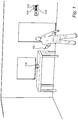
- Fig. 1 schematically illustrates a wireless communication system in an indoor environment.
- the communication system comprises a wireless mobile communication device, here represented by a portable phone 102, comprising an accelerometer.
- the phone 102 may for example be a DECT-phone, or a phone for use in a Wi-Fi-network.
- the system further comprises a first type of docking station 104, for simplicity referred to as type A, and a second type of docking station 106, referred to as type B.
- the docking station 104 of type A may for example be a docking station configured to hold a single phone 102, whereas the docking station 106 of type B is here shown as a wall mounted docking station configured to hold a plurality of devices.
- the wall mounted docking station 106 may for example be used for overnight storage and charging of phones meaning that the phone will not be monitored while in the docking station 106.
- the docking station 104 of type A is configured to hold the phone at a tilt angle A°.
- the tilt angle is here illustrated as the angle between the phone 102 and the vertical plane.
- the angle A may for example be approximately 36° ⁇ 5°.
- a docking station 106 of type B is illustrated, being configured to hold the phone at a tilt angle B°.
- the angle B may for example be approximately 13° ⁇ 5°.
- the given angles are merely examples, and essentially any angle may be used, as long as there is a detectable difference in angle between the two types of docking stations.
- the system described herein comprises two types of docking stations. The general concept of the invention is naturally applicable to a system comprising a larger number of docking stations, provided that the respective types of docking stations are configured to hold a mobile device at different angles.
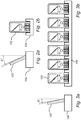
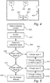
- FIG. 4 shows an example system 400 comprising a first type of docking station 402 (type A) and a second type of docking station 404 (type B), and with reference to the flow chart of Fig. 5 .
- a processing circuitry detects an electrical connection to a docking station, for example in the form of a charging current provided by the docking station.
- the accelerometer of the mobile device 102 is enabled in step 504.
- the accelerometer may for example be a capacitive micro machined accelerometer.
- Such an accelerometer is typically has an angle resolution as small as 0.1 ° ⁇ 0.002°.
- many different types of accelerometers may be used in the present context.
- the tilt angle of the mobile device may be determined 506.
- the tilt angle may also be referred to as an orientation angle an angle of inclination or the like, and the angle may be described with reference to the vertical plane, the horizontal plane or any other predetermined reference plane.
- This angular measurement is compared against pre-configured angular ranges which in turn correspond to the specific angles of the mobile device 102 when in docking stations of type "A" or "B" plus or minus a tolerance range allowing certain variations in the position of the charger itself.
- the tilt angle is 36° in a docking station of type A and 13° in a docking station of type B.
- the tolerance range may for example be ⁇ 5°. If more different types of docking stations are used, the tolerance range may have to be reduced, whereas if only two types of docking stations are used, the tolerance range may be higher.
- a tilt angle is determined by the accelerometer, the angle is compared to stored angles corresponding to known types of docking stations. If the angle is within an angle range corresponding to a docking station of type A, it is determined 508, 510 that the mobile device is arranged in a docking station of type A and the settings of the mobile device 102 are changed 512 to a predetermined set of settings specific for a docking station of type A.
- the angle is within an angle range corresponding to a docking station of type B, it is determined 514, 516 that the mobile device is arranged in a docking station of type B and the settings of the mobile device 102 are changed 518 to a predetermined set of settings specific for a docking station of type B.
- the settings of the mobile device 102 are maintained 520.
- the charging current for different docking stations may for example be set according to the following examples.
- Example 1 Docking station Type A provides a charging current of 500 mA.
- the charging current supplied to the battery by the charging IC will be set to 500 mA, to suit the power supply connected to the charger.
- Example 2 Docking station Type B provides a charging current of 1000 mA.
- the charging current supplied to the battery by the charging IC will be set to 1000 mA, to suit the power supply connected to the charger.
- a range of settings may be adjusted in the mobile device based on the detected docking station.
- parameters which can be set, and possible parameter values include:
- settings of the above set of parameters, and/or other parameter settings are preferably combined to form profiles, which may be stored in the mobile device 102 either as pre-programmed profiles or as user defined profiles. Based on the above a large number of combinations are possible and the profiles may be formed to suit any particular circumstance.
Landscapes
- Engineering & Computer Science (AREA)
- Signal Processing (AREA)
- Computer Networks & Wireless Communication (AREA)
- Human Computer Interaction (AREA)
- Power Engineering (AREA)
- Environmental & Geological Engineering (AREA)
- Telephone Function (AREA)
Claims (15)
- Andocksystem zum Laden einer drahtlosen Kommunikationsvorrichtung, umfassend:- eine drahtlose Kommunikationsvorrichtung (102), die einen Beschleunigungssensor umfasst;- eine erste Andockstation (104), die konfiguriert ist, um die drahtlose Kommunikationsvorrichtung in einem ersten Neigungswinkel zu halten und zu laden; und- eine zweite Andockstation (106), die konfiguriert ist, um die drahtlose Kommunikationsvorrichtung in einem zweiten Neigungswinkel zu halten und zu laden, wobei sich der zweite Winkel von dem ersten Winkel unterscheidet,- wobei die drahtlose Kommunikationsvorrichtung (102) ferner eine Verarbeitungsschaltung umfasst, die konfiguriert ist, um, wenn die drahtlose Kommunikationsvorrichtung in der ersten oder zweiten Andockstation platziert ist, zu funktionieren als:- eine Erfassungseinheit (102, 502) für elektrische Verbindungen, die konfiguriert ist, um eine elektrische Verbindung zwischen der drahtlosen Kommunikationsvorrichtung und der ersten oder zweiten Andockstation zu erfassen;- eine Aktivierungseinheit (102, 504), die konfiguriert ist, um den Beschleunigungssensor zu aktivieren, wenn die Erfassungseinheit für elektrische Verbindungen erfasst, dass die drahtlose Kommunikationsvorrichtung elektrisch mit der ersten oder zweiten Andockstation verbunden ist,- eine Orientierungserfassungseinheit (102, 506), die konfiguriert ist, um einen Neigungswinkel der drahtlosen Kommunikationsvorrichtung zu erfassen, wobei der Neigungswinkel durch den Beschleunigungssensor erfasst wird;- eine Identifikationseinheit (102, 508, 514), die konfiguriert ist, um basierend auf dem von der Orientierungserfassungseinheit erfassten Neigungswinkel zu identifizieren, ob die drahtlose Kommunikationsvorrichtung elektrisch entweder mit der ersten oder der zweiten Andockstation verbunden ist; und- eine Einstelleinheit (102, 512, 518, 520), die konfiguriert ist, um, wenn die Identifikationseinheit identifiziert, dass die drahtlose Kommunikationsvorrichtung elektrisch entweder mit der ersten oder zweiten Andockstation verbunden ist, die Ladeeigenschaften der drahtlosen Kommunikationsvorrichtung speziell für die identifizierte Andockstation einzustellen.
- System nach Anspruch 1, wobei die Einstelleinheit der Verarbeitungsschaltung konfiguriert ist, um einen Ladestrom basierend auf dem erfassten Winkel einzustellen.
- System nach Anspruch 2, wobei die Einstelleinheit der Verarbeitungsschaltung konfiguriert ist, um den Ladestrom auf einen Wert einzustellen, der durch einen maximalen Stromwert der identifizierten Andockstation und durch einen maximalen Stromwert einer Batterie der drahtlosen Kommunikationsvorrichtung begrenzt ist.
- System nach einem der vorhergehenden Ansprüche,- wobei die Identifikationseinheit konfiguriert ist, um die erste und zweite Andockstation zu identifizieren, wenn der erfasste Winkel innerhalb von ± 5° des ersten beziehungsweise zweiten Neigungswinkels liegt.
- System nach einem der vorhergehenden Ansprüche, wobei die Einstelleinheit der Verarbeitungsschaltung ferner konfiguriert ist, um basierend auf dem erfassten Winkel ein Konfigurationsprofil der drahtlosen Kommunikationsvorrichtung einzustellen.
- System nach Anspruch 5, wobei das Einstellen des Konfigurationsprofils ein Einstellen eines Ruftons, einer Ruflautstärke, einer Vibration, eines Anzeigeverhaltens und/oder eines Anrufempfangsstatus der drahtlosen Kommunikationsvorrichtung umfasst.
- System nach einem der vorhergehenden Ansprüche, wobei die erste Andockstation konfiguriert ist, um die drahtlose Kommunikationsvorrichtung in einem Neigungswinkel von etwa 13° zu halten und zu laden, und wobei die zweite Andockstation konfiguriert ist, um die drahtlose Kommunikationsvorrichtung in einem Neigungswinkel von etwa 36° zu halten und zu laden.
- Verfahren zum Einstellen der Ladeeigenschaften einer drahtlosen Kommunikationsvorrichtung in einem Andocksystem, das eine drahtlose Kommunikationsvorrichtung (102) umfassend einen Beschleunigungssensor, eine erste Andockstation (104), die konfiguriert ist, um die drahtlose Kommunikationsvorrichtung in einem ersten Neigungswinkel zu halten, und eine zweite Andockstation (106), die konfiguriert ist, um die drahtlose Kommunikationsvorrichtung in einem zweiten Neigungswinkel zu halten, umfasst, wobei der zweite Winkel von dem ersten Winkel unterschiedlich ist,- wobei das Verfahren die folgenden Schritte in der drahtlosen Kommunikationsvorrichtung umfasst:- Erfassen (502) einer elektrischen Verbindung zwischen der drahtlosen Kommunikationsvorrichtung und einer ersten oder zweiten Andockstation;- Aktivieren (504) des Beschleunigungssensors, wenn die drahtlose Kommunikationsvorrichtung eine elektrische Verbindung mit der ersten oder zweiten Andockstation erfasst hat;- Messen (506) eines Neigungswinkels der drahtlosen Kommunikationsvorrichtung unter Verwendung des Beschleunigungssensors;- Identifizieren (508, 514), basierend auf dem gemessenen Neigungswinkel, ob die drahtlose Kommunikationsvorrichtung elektrisch entweder mit der ersten oder der zweiten Andockstation verbunden ist; und- Einstellen (512, 518) eines Ladeprofils der drahtlosen Kommunikationsvorrichtung, das für die identifizierte Andockstation spezifisch ist.
- Verfahren nach Anspruch 8, wobei der Schritt des Identifizierens ferner ein Vergleichen des Neigungswinkels mit einem Satz von vorbestimmten Winkeln umfasst, wobei jeder vorbestimmte Winkel einem einzigartigen Typ von Andockstation entspricht.
- Verfahren nach Anspruch 8 oder 9, wobei der Schritt des Erfassens einer elektrischen Verbindung ein Bestimmen einer Spannung aus der ersten oder zweiten Andockstation umfasst.
- Verfahren nach einem der Ansprüche 8 bis 10, wobei der Schritt des Identifizierens ferner ein Anpassen des gemessenen Neigungswinkels an einen von einem vorbestimmten Satz von Winkelbereichen umfasst.
- Verfahren nach Anspruch 11, wobei jeder der Winkelbereiche einem einzigartigen Typ von Andockstation entspricht.
- Verfahren nach Anspruch 11, wobei, wenn der gemessene Neigungswinkel nicht einem der vorbestimmten Winkelbereiche entspricht, die Einstellungen der drahtlosen Kommunikationsvorrichtung beibehalten werden.
- Verfahren nach einem der Ansprüche 8 bis 13, wobei der Schritt des Einstellens eines Ladeprofils ferner ein Einstellen eines Ruftons, einer Ruflautstärke, einer Vibration, eines Anzeigeverhaltens und/oder eines Anrufempfangsstatus der drahtlosen Kommunikationsvorrichtung umfasst.
- Verfahren nach Anspruch 14, wobei Einstellen des Anrufempfangsstatus ein Einstellen einer automatisierten Antwort, Weiterleitung oder Ablehnung eines eingehenden Anrufs umfasst.
Priority Applications (2)
| Application Number | Priority Date | Filing Date | Title |
|---|---|---|---|
| EP13196642.6A EP2884725B1 (de) | 2013-12-11 | 2013-12-11 | Andocksystem für eine drahtlose Kommunikationsvorrichtung |
| US14/566,230 US9432072B2 (en) | 2013-12-11 | 2014-12-10 | Docking system for a wireless communication device |
Applications Claiming Priority (1)
| Application Number | Priority Date | Filing Date | Title |
|---|---|---|---|
| EP13196642.6A EP2884725B1 (de) | 2013-12-11 | 2013-12-11 | Andocksystem für eine drahtlose Kommunikationsvorrichtung |
Publications (2)
| Publication Number | Publication Date |
|---|---|
| EP2884725A1 EP2884725A1 (de) | 2015-06-17 |
| EP2884725B1 true EP2884725B1 (de) | 2019-07-03 |
Family
ID=49765353
Family Applications (1)
| Application Number | Title | Priority Date | Filing Date |
|---|---|---|---|
| EP13196642.6A Active EP2884725B1 (de) | 2013-12-11 | 2013-12-11 | Andocksystem für eine drahtlose Kommunikationsvorrichtung |
Country Status (2)
| Country | Link |
|---|---|
| US (1) | US9432072B2 (de) |
| EP (1) | EP2884725B1 (de) |
Families Citing this family (3)
| Publication number | Priority date | Publication date | Assignee | Title |
|---|---|---|---|---|
| KR102504308B1 (ko) * | 2016-03-02 | 2023-02-28 | 삼성전자주식회사 | 디스플레이의 밝기를 제어하는 방법, 전자 장치 및 컴퓨터 판독가능 기록매체 |
| US10122184B2 (en) * | 2016-09-15 | 2018-11-06 | Blackberry Limited | Application of modulated vibrations in docking scenarios |
| US10957445B2 (en) | 2017-10-05 | 2021-03-23 | Hill-Rom Services, Inc. | Caregiver and staff information system |
Citations (1)
| Publication number | Priority date | Publication date | Assignee | Title |
|---|---|---|---|---|
| US20100167794A1 (en) * | 2008-12-25 | 2010-07-01 | Inventec Appliances Corp. | Mobile phone and method for automatically switching between incoming call alert modes of mobile phone |
Family Cites Families (9)
| Publication number | Priority date | Publication date | Assignee | Title |
|---|---|---|---|---|
| US6888338B1 (en) * | 2003-01-27 | 2005-05-03 | O2Micro International Limited | Portable computer and docking station having charging circuits with remote power sensing capabilities |
| CN101919273B (zh) | 2007-11-09 | 2013-07-10 | 谷歌公司 | 基于加速度计数据激活应用 |
| US8676224B2 (en) | 2008-02-19 | 2014-03-18 | Apple Inc. | Speakerphone control for mobile device |
| US20110099507A1 (en) | 2009-10-28 | 2011-04-28 | Google Inc. | Displaying a collection of interactive elements that trigger actions directed to an item |
| US8682399B2 (en) | 2009-12-15 | 2014-03-25 | Apple Inc. | Detecting docking status of a portable device using motion sensor data |
| US20110230209A1 (en) * | 2010-03-22 | 2011-09-22 | Dsp Group Ltd. | Method and Mobile Device for Automatic Activation of Applications |
| US9241064B2 (en) * | 2010-05-28 | 2016-01-19 | Google Technology Holdings LLC | Smart method and device for adaptive user interface experiences |
| US8847545B2 (en) * | 2011-03-28 | 2014-09-30 | Htc Corporation | Systems and methods for automatically invoking certain operations in mobile phones |
| US9653938B2 (en) | 2011-12-14 | 2017-05-16 | Nokia Technologies Oy | Method and apparatus for improving electronics devices wireless charging using inertial sensors |
-
2013
- 2013-12-11 EP EP13196642.6A patent/EP2884725B1/de active Active
-
2014
- 2014-12-10 US US14/566,230 patent/US9432072B2/en active Active
Patent Citations (1)
| Publication number | Priority date | Publication date | Assignee | Title |
|---|---|---|---|---|
| US20100167794A1 (en) * | 2008-12-25 | 2010-07-01 | Inventec Appliances Corp. | Mobile phone and method for automatically switching between incoming call alert modes of mobile phone |
Also Published As
| Publication number | Publication date |
|---|---|
| EP2884725A1 (de) | 2015-06-17 |
| US20150162945A1 (en) | 2015-06-11 |
| US9432072B2 (en) | 2016-08-30 |
Similar Documents
| Publication | Publication Date | Title |
|---|---|---|
| HK1210553A1 (en) | Docking system for a wireless communication device | |
| KR101493581B1 (ko) | 적응적 사용자 인터페이스 경험을 위한 스마트한 방법 및 장치 | |
| US11201359B2 (en) | Charging control method and apparatus, and computer readable storage medium | |
| US20220393498A1 (en) | Portable wireless charging apparatus and system | |
| CN113475051B (zh) | 用于根据无线电力共享提供用户界面的装置和方法 | |
| JP5902867B2 (ja) | オーディオインターフェイスの自己適応方法、装置およびオーディオ情報受信装置 | |
| KR102810012B1 (ko) | 무선 충전 장치 및 방법 | |
| KR102688106B1 (ko) | 무선 전송 전력을 제어하는 방법 및 이를 구현한 전자 장치 | |
| KR20080056525A (ko) | 휴대용 단말기의 블루투스 연결 장치 및 방법 | |
| TW201724690A (zh) | 控制充電的方法、裝置、電源轉接器和移動終端 | |
| CN106340925A (zh) | 一种充电控制方法、装置及终端 | |
| KR20200101035A (ko) | 전자 장치 및 전자 장치에서 외부 객체 검출 기반의 무선 전력 전송 방법 | |
| EP2884725B1 (de) | Andocksystem für eine drahtlose Kommunikationsvorrichtung | |
| US9857846B2 (en) | Portable computing device cover including a keyboard | |
| CN103929696B (zh) | 一种耳机检测处理方法、装置及移动终端 | |
| CN103872732A (zh) | 移动终端及其充电控制方法 | |
| KR102813607B1 (ko) | 무선 충전 방법 및 이를 지원하는 전자 장치 | |
| KR20200042376A (ko) | 전자 장치 및 전자 장치에서 유무선 충전 방법 | |
| CN104219729B (zh) | 一种连接处理方法及电子设备 | |
| KR20210089906A (ko) | 무선 전력 공유 기능을 빠르게 실행하는 전자 장치 및 그 방법 | |
| KR20210101705A (ko) | 무선 충전 방법 및 이를 지원하는 전자 장치 | |
| US10141995B2 (en) | Method for selecting antenna and electronic device | |
| KR102811972B1 (ko) | 전자 장치 및 전자 장치에서 무선 충전 가이드 정보 제공 방법 | |
| KR20210128607A (ko) | 전자 장치 및 상기 전자 장치의 충전 상태 정보를 제공하는 방법 | |
| KR20210146123A (ko) | 충전을 제어하는 방법 및 장치 |
Legal Events
| Date | Code | Title | Description |
|---|---|---|---|
| PUAI | Public reference made under article 153(3) epc to a published international application that has entered the european phase |
Free format text: ORIGINAL CODE: 0009012 |
|
| 17P | Request for examination filed |
Effective date: 20131211 |
|
| AK | Designated contracting states |
Kind code of ref document: A1 Designated state(s): AL AT BE BG CH CY CZ DE DK EE ES FI FR GB GR HR HU IE IS IT LI LT LU LV MC MK MT NL NO PL PT RO RS SE SI SK SM TR |
|
| AX | Request for extension of the european patent |
Extension state: BA ME |
|
| R17P | Request for examination filed (corrected) |
Effective date: 20151111 |
|
| RBV | Designated contracting states (corrected) |
Designated state(s): AL AT BE BG CH CY CZ DE DK EE ES FI FR GB GR HR HU IE IS IT LI LT LU LV MC MK MT NL NO PL PT RO RS SE SI SK SM TR |
|
| REG | Reference to a national code |
Ref country code: HK Ref legal event code: DE Ref document number: 1210553 Country of ref document: HK |
|
| STAA | Information on the status of an ep patent application or granted ep patent |
Free format text: STATUS: EXAMINATION IS IN PROGRESS |
|
| 17Q | First examination report despatched |
Effective date: 20180605 |
|
| GRAP | Despatch of communication of intention to grant a patent |
Free format text: ORIGINAL CODE: EPIDOSNIGR1 |
|
| STAA | Information on the status of an ep patent application or granted ep patent |
Free format text: STATUS: GRANT OF PATENT IS INTENDED |
|
| INTG | Intention to grant announced |
Effective date: 20190111 |
|
| GRAS | Grant fee paid |
Free format text: ORIGINAL CODE: EPIDOSNIGR3 |
|
| GRAA | (expected) grant |
Free format text: ORIGINAL CODE: 0009210 |
|
| STAA | Information on the status of an ep patent application or granted ep patent |
Free format text: STATUS: THE PATENT HAS BEEN GRANTED |
|
| AK | Designated contracting states |
Kind code of ref document: B1 Designated state(s): AL AT BE BG CH CY CZ DE DK EE ES FI FR GB GR HR HU IE IS IT LI LT LU LV MC MK MT NL NO PL PT RO RS SE SI SK SM TR |
|
| REG | Reference to a national code |
Ref country code: GB Ref legal event code: FG4D |
|
| REG | Reference to a national code |
Ref country code: CH Ref legal event code: EP Ref country code: AT Ref legal event code: REF Ref document number: 1152387 Country of ref document: AT Kind code of ref document: T Effective date: 20190715 |
|
| REG | Reference to a national code |
Ref country code: IE Ref legal event code: FG4D |
|
| REG | Reference to a national code |
Ref country code: DE Ref legal event code: R096 Ref document number: 602013057337 Country of ref document: DE |
|
| REG | Reference to a national code |
Ref country code: NL Ref legal event code: FP |
|
| REG | Reference to a national code |
Ref country code: SE Ref legal event code: TRGR |
|
| REG | Reference to a national code |
Ref country code: LT Ref legal event code: MG4D |
|
| REG | Reference to a national code |
Ref country code: AT Ref legal event code: MK05 Ref document number: 1152387 Country of ref document: AT Kind code of ref document: T Effective date: 20190703 |
|
| PG25 | Lapsed in a contracting state [announced via postgrant information from national office to epo] |
Ref country code: BG Free format text: LAPSE BECAUSE OF FAILURE TO SUBMIT A TRANSLATION OF THE DESCRIPTION OR TO PAY THE FEE WITHIN THE PRESCRIBED TIME-LIMIT Effective date: 20191003 Ref country code: CZ Free format text: LAPSE BECAUSE OF FAILURE TO SUBMIT A TRANSLATION OF THE DESCRIPTION OR TO PAY THE FEE WITHIN THE PRESCRIBED TIME-LIMIT Effective date: 20190703 Ref country code: LT Free format text: LAPSE BECAUSE OF FAILURE TO SUBMIT A TRANSLATION OF THE DESCRIPTION OR TO PAY THE FEE WITHIN THE PRESCRIBED TIME-LIMIT Effective date: 20190703 Ref country code: HR Free format text: LAPSE BECAUSE OF FAILURE TO SUBMIT A TRANSLATION OF THE DESCRIPTION OR TO PAY THE FEE WITHIN THE PRESCRIBED TIME-LIMIT Effective date: 20190703 Ref country code: FI Free format text: LAPSE BECAUSE OF FAILURE TO SUBMIT A TRANSLATION OF THE DESCRIPTION OR TO PAY THE FEE WITHIN THE PRESCRIBED TIME-LIMIT Effective date: 20190703 Ref country code: PT Free format text: LAPSE BECAUSE OF FAILURE TO SUBMIT A TRANSLATION OF THE DESCRIPTION OR TO PAY THE FEE WITHIN THE PRESCRIBED TIME-LIMIT Effective date: 20191104 Ref country code: AT Free format text: LAPSE BECAUSE OF FAILURE TO SUBMIT A TRANSLATION OF THE DESCRIPTION OR TO PAY THE FEE WITHIN THE PRESCRIBED TIME-LIMIT Effective date: 20190703 Ref country code: NO Free format text: LAPSE BECAUSE OF FAILURE TO SUBMIT A TRANSLATION OF THE DESCRIPTION OR TO PAY THE FEE WITHIN THE PRESCRIBED TIME-LIMIT Effective date: 20191003 |
|
| PG25 | Lapsed in a contracting state [announced via postgrant information from national office to epo] |
Ref country code: AL Free format text: LAPSE BECAUSE OF FAILURE TO SUBMIT A TRANSLATION OF THE DESCRIPTION OR TO PAY THE FEE WITHIN THE PRESCRIBED TIME-LIMIT Effective date: 20190703 Ref country code: ES Free format text: LAPSE BECAUSE OF FAILURE TO SUBMIT A TRANSLATION OF THE DESCRIPTION OR TO PAY THE FEE WITHIN THE PRESCRIBED TIME-LIMIT Effective date: 20190703 Ref country code: IS Free format text: LAPSE BECAUSE OF FAILURE TO SUBMIT A TRANSLATION OF THE DESCRIPTION OR TO PAY THE FEE WITHIN THE PRESCRIBED TIME-LIMIT Effective date: 20191103 Ref country code: GR Free format text: LAPSE BECAUSE OF FAILURE TO SUBMIT A TRANSLATION OF THE DESCRIPTION OR TO PAY THE FEE WITHIN THE PRESCRIBED TIME-LIMIT Effective date: 20191004 Ref country code: LV Free format text: LAPSE BECAUSE OF FAILURE TO SUBMIT A TRANSLATION OF THE DESCRIPTION OR TO PAY THE FEE WITHIN THE PRESCRIBED TIME-LIMIT Effective date: 20190703 Ref country code: RS Free format text: LAPSE BECAUSE OF FAILURE TO SUBMIT A TRANSLATION OF THE DESCRIPTION OR TO PAY THE FEE WITHIN THE PRESCRIBED TIME-LIMIT Effective date: 20190703 |
|
| PG25 | Lapsed in a contracting state [announced via postgrant information from national office to epo] |
Ref country code: TR Free format text: LAPSE BECAUSE OF FAILURE TO SUBMIT A TRANSLATION OF THE DESCRIPTION OR TO PAY THE FEE WITHIN THE PRESCRIBED TIME-LIMIT Effective date: 20190703 |
|
| PG25 | Lapsed in a contracting state [announced via postgrant information from national office to epo] |
Ref country code: IT Free format text: LAPSE BECAUSE OF FAILURE TO SUBMIT A TRANSLATION OF THE DESCRIPTION OR TO PAY THE FEE WITHIN THE PRESCRIBED TIME-LIMIT Effective date: 20190703 Ref country code: RO Free format text: LAPSE BECAUSE OF FAILURE TO SUBMIT A TRANSLATION OF THE DESCRIPTION OR TO PAY THE FEE WITHIN THE PRESCRIBED TIME-LIMIT Effective date: 20190703 Ref country code: PL Free format text: LAPSE BECAUSE OF FAILURE TO SUBMIT A TRANSLATION OF THE DESCRIPTION OR TO PAY THE FEE WITHIN THE PRESCRIBED TIME-LIMIT Effective date: 20190703 Ref country code: EE Free format text: LAPSE BECAUSE OF FAILURE TO SUBMIT A TRANSLATION OF THE DESCRIPTION OR TO PAY THE FEE WITHIN THE PRESCRIBED TIME-LIMIT Effective date: 20190703 Ref country code: DK Free format text: LAPSE BECAUSE OF FAILURE TO SUBMIT A TRANSLATION OF THE DESCRIPTION OR TO PAY THE FEE WITHIN THE PRESCRIBED TIME-LIMIT Effective date: 20190703 |
|
| PG25 | Lapsed in a contracting state [announced via postgrant information from national office to epo] |
Ref country code: SK Free format text: LAPSE BECAUSE OF FAILURE TO SUBMIT A TRANSLATION OF THE DESCRIPTION OR TO PAY THE FEE WITHIN THE PRESCRIBED TIME-LIMIT Effective date: 20190703 Ref country code: IS Free format text: LAPSE BECAUSE OF FAILURE TO SUBMIT A TRANSLATION OF THE DESCRIPTION OR TO PAY THE FEE WITHIN THE PRESCRIBED TIME-LIMIT Effective date: 20200224 Ref country code: SM Free format text: LAPSE BECAUSE OF FAILURE TO SUBMIT A TRANSLATION OF THE DESCRIPTION OR TO PAY THE FEE WITHIN THE PRESCRIBED TIME-LIMIT Effective date: 20190703 |
|
| REG | Reference to a national code |
Ref country code: DE Ref legal event code: R097 Ref document number: 602013057337 Country of ref document: DE |
|
| PLBE | No opposition filed within time limit |
Free format text: ORIGINAL CODE: 0009261 |
|
| STAA | Information on the status of an ep patent application or granted ep patent |
Free format text: STATUS: NO OPPOSITION FILED WITHIN TIME LIMIT |
|
| PG2D | Information on lapse in contracting state deleted |
Ref country code: IS |
|
| REG | Reference to a national code |
Ref country code: CH Ref legal event code: PL |
|
| 26N | No opposition filed |
Effective date: 20200603 |
|
| REG | Reference to a national code |
Ref country code: BE Ref legal event code: MM Effective date: 20191231 |
|
| PG25 | Lapsed in a contracting state [announced via postgrant information from national office to epo] |
Ref country code: MC Free format text: LAPSE BECAUSE OF FAILURE TO SUBMIT A TRANSLATION OF THE DESCRIPTION OR TO PAY THE FEE WITHIN THE PRESCRIBED TIME-LIMIT Effective date: 20190703 Ref country code: SI Free format text: LAPSE BECAUSE OF FAILURE TO SUBMIT A TRANSLATION OF THE DESCRIPTION OR TO PAY THE FEE WITHIN THE PRESCRIBED TIME-LIMIT Effective date: 20190703 |
|
| GBPC | Gb: european patent ceased through non-payment of renewal fee |
Effective date: 20191211 |
|
| PG25 | Lapsed in a contracting state [announced via postgrant information from national office to epo] |
Ref country code: IE Free format text: LAPSE BECAUSE OF NON-PAYMENT OF DUE FEES Effective date: 20191211 Ref country code: LU Free format text: LAPSE BECAUSE OF NON-PAYMENT OF DUE FEES Effective date: 20191211 Ref country code: FR Free format text: LAPSE BECAUSE OF NON-PAYMENT OF DUE FEES Effective date: 20191231 Ref country code: GB Free format text: LAPSE BECAUSE OF NON-PAYMENT OF DUE FEES Effective date: 20191211 |
|
| PG25 | Lapsed in a contracting state [announced via postgrant information from national office to epo] |
Ref country code: BE Free format text: LAPSE BECAUSE OF NON-PAYMENT OF DUE FEES Effective date: 20191231 Ref country code: CH Free format text: LAPSE BECAUSE OF NON-PAYMENT OF DUE FEES Effective date: 20191231 Ref country code: LI Free format text: LAPSE BECAUSE OF NON-PAYMENT OF DUE FEES Effective date: 20191231 |
|
| PG25 | Lapsed in a contracting state [announced via postgrant information from national office to epo] |
Ref country code: CY Free format text: LAPSE BECAUSE OF FAILURE TO SUBMIT A TRANSLATION OF THE DESCRIPTION OR TO PAY THE FEE WITHIN THE PRESCRIBED TIME-LIMIT Effective date: 20190703 |
|
| PG25 | Lapsed in a contracting state [announced via postgrant information from national office to epo] |
Ref country code: MT Free format text: LAPSE BECAUSE OF FAILURE TO SUBMIT A TRANSLATION OF THE DESCRIPTION OR TO PAY THE FEE WITHIN THE PRESCRIBED TIME-LIMIT Effective date: 20190703 Ref country code: HU Free format text: LAPSE BECAUSE OF FAILURE TO SUBMIT A TRANSLATION OF THE DESCRIPTION OR TO PAY THE FEE WITHIN THE PRESCRIBED TIME-LIMIT; INVALID AB INITIO Effective date: 20131211 |
|
| PG25 | Lapsed in a contracting state [announced via postgrant information from national office to epo] |
Ref country code: MK Free format text: LAPSE BECAUSE OF FAILURE TO SUBMIT A TRANSLATION OF THE DESCRIPTION OR TO PAY THE FEE WITHIN THE PRESCRIBED TIME-LIMIT Effective date: 20190703 |
|
| PGFP | Annual fee paid to national office [announced via postgrant information from national office to epo] |
Ref country code: DE Payment date: 20241210 Year of fee payment: 12 |
|
| PGFP | Annual fee paid to national office [announced via postgrant information from national office to epo] |
Ref country code: NL Payment date: 20241219 Year of fee payment: 12 |
|
| PGFP | Annual fee paid to national office [announced via postgrant information from national office to epo] |
Ref country code: SE Payment date: 20241219 Year of fee payment: 12 |