EP2884657A1 - Atténuation d'harmoniques dans des systèmes générateur-conversion à multiphase - Google Patents
Atténuation d'harmoniques dans des systèmes générateur-conversion à multiphase Download PDFInfo
- Publication number
- EP2884657A1 EP2884657A1 EP13382510.9A EP13382510A EP2884657A1 EP 2884657 A1 EP2884657 A1 EP 2884657A1 EP 13382510 A EP13382510 A EP 13382510A EP 2884657 A1 EP2884657 A1 EP 2884657A1
- Authority
- EP
- European Patent Office
- Prior art keywords
- stators
- generator
- active filtering
- converter
- conversion system
- Prior art date
- Legal status (The legal status is an assumption and is not a legal conclusion. Google has not performed a legal analysis and makes no representation as to the accuracy of the status listed.)
- Granted
Links
- 238000006243 chemical reaction Methods 0.000 title claims abstract description 85
- 230000000116 mitigating effect Effects 0.000 title claims abstract description 18
- 238000001914 filtration Methods 0.000 claims abstract description 71
- 230000004907 flux Effects 0.000 claims abstract description 19
- 230000008878 coupling Effects 0.000 claims abstract description 18
- 238000010168 coupling process Methods 0.000 claims abstract description 18
- 238000005859 coupling reaction Methods 0.000 claims abstract description 18
- 238000000034 method Methods 0.000 claims abstract description 8
- 238000004804 winding Methods 0.000 claims description 18
- 238000005259 measurement Methods 0.000 description 5
- 230000008901 benefit Effects 0.000 description 4
- 230000001276 controlling effect Effects 0.000 description 4
- 238000013461 design Methods 0.000 description 4
- 238000010586 diagram Methods 0.000 description 4
- 238000000605 extraction Methods 0.000 description 4
- 239000011159 matrix material Substances 0.000 description 4
- 230000001105 regulatory effect Effects 0.000 description 4
- 238000004513 sizing Methods 0.000 description 3
- 230000001010 compromised effect Effects 0.000 description 2
- 230000009466 transformation Effects 0.000 description 2
- 238000004891 communication Methods 0.000 description 1
- 238000011156 evaluation Methods 0.000 description 1
- 230000010354 integration Effects 0.000 description 1
- 238000012423 maintenance Methods 0.000 description 1
- 230000007257 malfunction Effects 0.000 description 1
- 238000012986 modification Methods 0.000 description 1
- 230000004048 modification Effects 0.000 description 1
- 230000003449 preventive effect Effects 0.000 description 1
- 238000013441 quality evaluation Methods 0.000 description 1
- 239000004065 semiconductor Substances 0.000 description 1
Images


Classifications
-
- H—ELECTRICITY
- H02—GENERATION; CONVERSION OR DISTRIBUTION OF ELECTRIC POWER
- H02P—CONTROL OR REGULATION OF ELECTRIC MOTORS, ELECTRIC GENERATORS OR DYNAMO-ELECTRIC CONVERTERS; CONTROLLING TRANSFORMERS, REACTORS OR CHOKE COILS
- H02P9/00—Arrangements for controlling electric generators for the purpose of obtaining a desired output
- H02P9/40—Arrangements for controlling electric generators for the purpose of obtaining a desired output by variation of reluctance of magnetic circuit of generator
-
- H—ELECTRICITY
- H02—GENERATION; CONVERSION OR DISTRIBUTION OF ELECTRIC POWER
- H02P—CONTROL OR REGULATION OF ELECTRIC MOTORS, ELECTRIC GENERATORS OR DYNAMO-ELECTRIC CONVERTERS; CONTROLLING TRANSFORMERS, REACTORS OR CHOKE COILS
- H02P9/00—Arrangements for controlling electric generators for the purpose of obtaining a desired output
- H02P9/10—Control effected upon generator excitation circuit to reduce harmful effects of overloads or transients, e.g. sudden application of load, sudden removal of load, sudden change of load
- H02P9/105—Control effected upon generator excitation circuit to reduce harmful effects of overloads or transients, e.g. sudden application of load, sudden removal of load, sudden change of load for increasing the stability
-
- H—ELECTRICITY
- H02—GENERATION; CONVERSION OR DISTRIBUTION OF ELECTRIC POWER
- H02P—CONTROL OR REGULATION OF ELECTRIC MOTORS, ELECTRIC GENERATORS OR DYNAMO-ELECTRIC CONVERTERS; CONTROLLING TRANSFORMERS, REACTORS OR CHOKE COILS
- H02P21/00—Arrangements or methods for the control of electric machines by vector control, e.g. by control of field orientation
- H02P21/24—Vector control not involving the use of rotor position or rotor speed sensors
-
- H—ELECTRICITY
- H02—GENERATION; CONVERSION OR DISTRIBUTION OF ELECTRIC POWER
- H02P—CONTROL OR REGULATION OF ELECTRIC MOTORS, ELECTRIC GENERATORS OR DYNAMO-ELECTRIC CONVERTERS; CONTROLLING TRANSFORMERS, REACTORS OR CHOKE COILS
- H02P9/00—Arrangements for controlling electric generators for the purpose of obtaining a desired output
- H02P9/02—Details of the control
-
- H—ELECTRICITY
- H02—GENERATION; CONVERSION OR DISTRIBUTION OF ELECTRIC POWER
- H02P—CONTROL OR REGULATION OF ELECTRIC MOTORS, ELECTRIC GENERATORS OR DYNAMO-ELECTRIC CONVERTERS; CONTROLLING TRANSFORMERS, REACTORS OR CHOKE COILS
- H02P9/00—Arrangements for controlling electric generators for the purpose of obtaining a desired output
- H02P9/14—Arrangements for controlling electric generators for the purpose of obtaining a desired output by variation of field
- H02P9/26—Arrangements for controlling electric generators for the purpose of obtaining a desired output by variation of field using discharge tubes or semiconductor devices
- H02P9/30—Arrangements for controlling electric generators for the purpose of obtaining a desired output by variation of field using discharge tubes or semiconductor devices using semiconductor devices
-
- H—ELECTRICITY
- H02—GENERATION; CONVERSION OR DISTRIBUTION OF ELECTRIC POWER
- H02P—CONTROL OR REGULATION OF ELECTRIC MOTORS, ELECTRIC GENERATORS OR DYNAMO-ELECTRIC CONVERTERS; CONTROLLING TRANSFORMERS, REACTORS OR CHOKE COILS
- H02P2101/00—Special adaptation of control arrangements for generators
- H02P2101/15—Special adaptation of control arrangements for generators for wind-driven turbines
Definitions
- the present disclosure relates to multiphase generators and more specifically to multiphase generator-conversion systems and methods of mitigating harmonics in such systems.
- Wind turbines have to comply with certain standards regarding the quality of the power they generate. These standards are typically adopted by the electrical network operators in their respective grid codes, in which they determine the technical requirements for wind facilities for their grid integration.
- the power quality evaluation comprises, among other aspects, the evaluation of the harmonic components in current and voltage waveforms at the connection point of the wind facility with the electrical network. Harmonic components may be provoked by generator imperfections or may be generated by the converters at the conversion lines.
- the study of harmonics on the generator side is relevant for wind turbine facilities because, among other aspects, harmonic currents flowing through the windings of the generators may provoke mechanical vibrations, which can diminish the life of their mechanical parts. Furthermore, they can increase the electrical power losses affecting the efficiency of the machine. Moreover, from the point of view of the management and control of the wind turbine, they can provoke measurement errors and interferences in communication systems.
- the harmonic emission in wind turbines can be affected, among others, by the following aspects: i) the use of electronic power devices; and ii) the electromechanical design of the generators.
- the desired voltage waveforms at the stator terminals of the generators, and also at the grid connection point of variable speed wind turbines are obtained by the switching of electronic power converters.
- the obtained waveforms are not purely sinusoidal but contain harmonic components.
- the electromechanical design of the generator it is worth highlighting that the design of the windings, the stator and the rotor of the generator may affect the magnetic flux within the generator and thus the circulation of harmonic currents through it, and from it to the power converters which connect the system with the external grid.
- DC wind turbine power plants are wind turbine power plants with a DC collection grid, instead of a conventional AC collection grid.
- the output of the wind turbines power conversion systems must be in DC.
- Power converters typically affect both the harmonic emission from the wind turbine to the DC collection grid of the DC wind power plant, as well as the harmonic currents flowing through the electrical generator of the wind turbines.
- the present disclosure relates to various methods and devices for avoiding or at least partly reducing this problem.
- a multiphase generator-conversion system comprises a multiphase generator having one rotor and m+1 number of electromagnetically coupled stators, m being a natural number.
- Each stator comprises a plurality of phase legs.
- the multiphase generator-conversion system further comprises a converter having m+1 conversion lines. Each conversion line is connected to the plurality of phase legs of one of said m+1 stators.
- Each conversion line comprises a rectification module. At most m of the m+1 rectification modules comprise an active filtering converter, respectively. At least one of the m+1 rectification modules comprises a passive rectifier, such as a diode rectifier.
- At least one of the active filtering converters is arranged to directly control its current to vary or affect the magnetic flux of the stator to which it is connected and to indirectly modify or affect the magnetic flux of the rest of the stators through the electromagnetic coupling between them to mitigate the harmonic content. This way, mitigation of the harmonic content both of the stator to which it is connected and also of the other machine stators is achieved.
- the m+1 stators may be in phase with each other. Therefore, each phase line of each stator may be in phase with a corresponding phase of the other stators. For example, in a 3-stator, and 3-phase/stator configuration, all stators may carry 3 phases 120° apart (e.g. at 0°, 120°, 240°). In other implementations, the m+1 stators may be completely out of phase meaning that no single phase line may carry the same phase as another phase line of another stator.
- each stator may carry 3 phases 120° apart, but, e.g., the first stator may have 3 phases at 0°, 120°, 240°, the second stator at 40°, 160°, 280° and the third stator at 80°, 200°, 320°.
- phase leg and “winding” may be used indiscriminately and denote a coil carrying one phase of a stator.
- the L s inductance matrix (Eq. 3) is the equation which represents the magnetic coupling between all the generator phases.
- L s L 1 , 1 M 1 , 2 M 1 , 3 M 1 , n - 2 M 1 , n - 1 M 1 , n M 2 , 1 L 2 , 2 M 2 , 3 ⁇ M 2 , n - 2 M 2 , n - 1 M 2 , n M 3 , 1 M 3 , 2 L 3 , 3 M 3 , n - 2 M 3 , n - 1 M 3 , n ⁇ ⁇ ⁇ M n - 2 , 1 M n - 2 , 2 M n - 2 , 3 M n - 2 , n - 2 M n - 2 , n - 1 M n - 2 , 1 M n - 1 , 2 M n - 2 , 3 M n - 2 , n - 2 M
- a multiphase generator 110 is shown with i three-phase stators connected to diode rectifiers 122-1 to 122-i, respectively.
- the AC currents of this machine are rectified and injected to three different DC bus voltages (which may or may not be connected to the same DC bus). Due to the machine space harmonics and the current rectification using diode rectifiers, the currents may be polluted with several orders of harmonics.
- these current harmonics are not producing any torque, thus the system should eliminate them.
- these harmonics may be compensated connecting an active filtering converter.
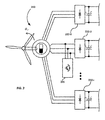
- the active filtering converter may be connected in parallel with the AC machine stators, as it is shown in Fig. 2 .
- Generator 210 is similarly shown with i three-phase stators connected to diode rectifiers 222-1 to 222-i, respectively.
- An active filtering converter 235 is connected at the input of diode rectifier 222-2 in a shunt configuration.
- this configuration is merely an example and it is referred here to explain the principle of the invention.
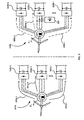
- FIG. 3 shows a conceptual diagram of the multiple three-phase stator generators with diode rectifier converter with and without active filtering.
- Left picture shows generator 310a connected to diode rectifiers 322a-1 to 322a-i and does not include any active filtering stage. Therefore the currents, indicated with black lines 305a-1 to 305a-i, flowing through the circuit may be polluted.
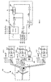
- a generator-conversion system 410 comprises generator 415 connected to diode rectifiers 422-1 to 422-i.
- An active filtering converter 435 is connected at the input of diode rectifier 422-2 in a shunt configuration. All the currents i s ⁇ 1 abc to i si abc of the AC systems are measured. They are introduced into controller 436.
- Controller 436 may form part of active filtering converter 435 or it may be external to active filtering converter 435. Furthermore, it may control one or more active filtering converters.
- Controller 436 calculates a current vector i s,T ( ⁇ e ) for the n phases. This vector results from the application of the transformation T ( ⁇ e ) to the measured current vector i si abc containing the instantaneous current measurements of the phases of the generator.
- the reference torque ⁇ *, the voltages V DC 1 to V DCi and the electrical machine angle ⁇ e are introduced in Reference Calculation module 437 to generate the current vector reference i s , T ⁇ e * for the controller.
- the i s,T ( ⁇ e ) and i s , T ⁇ e * vector corresponding components are compared at an adding module and the result is introduced in the Controller and Harmonic compensation block 438.
- Controller & Harmonic compensation block 438 further receives the electrical machine angle ⁇ e value to generate a filtering current vector i c * .
- the current reference vector i c * is then used to generate the individual current references i c abc * through the transformation T c - 1 ⁇ e to be introduced in the current control module 439 that is in charge of regulating the current flowing through the active filter 435 circuit, connected at the input of diode rectifier 422-2, to the defined reference values i c abc * .
- the active filtering converter is able to control a current (denoted as i c abc * ) to reduce the harmonic content flowing through the machine circuits.
- each active filtering converter may be arranged to receive the values of the currents of the phase legs of all stators and calculate a current that reduces the amount of harmonic content from all stators when applied to the stator to which it is connected.
- the active filtering converter would, thus, comprise a controller such as controller 436 described with reference to Fig. 4 .
- the currents may be received by one controlling module that calculates the mentioned current.
- each may contain a controlling module or share a common controlling module arranged with one active filtering converter for calculating the required currents of each active filtering converter.
- each rectification module may comprise a diode rectifier and each rectifier may be connected to one of the m+1 stators and the active filtering converters may each be connected to the conversion line between one of the m+1 stators and its respective diode rectifier in a shunt configuration.
- the active filtering converter may simply be added for reducing the harmonic emission, but it may not be in charge of the power extraction from one of the stators of the generator. Consequently, its size may be reduced in comparison with the size of the active filtering converter of the previous embodiments.
- the active filtering converter gets broken, the power extraction from the stator of the wind turbine to the diode rectifier that it is connected to may not be compromised.
- each of the m+1 conversion lines may comprise either one of the active filtering converters or the at least one diode rectifier and each of said active filtering converters or diode rectifiers may be connected to a different one of the m+1 stators. Therefore, the active filtering converters may also act as rectifiers for their respective stators of the multiphase generator. The active filtering converters may rectify the AC output of one of the stators of the AC multiphase generator. The effective replacement of a diode rectifier by a controlled active filtering converter may enable a more precise control of the currents flowing through one of the stators of the generator.
- each rectification module may comprise a diode rectifier and each diode rectifier may be connected to one of the m+1 stators and the converter may further comprise at least one active filtering converter.
- a switching circuit may be arranged between said at least one active filtering converter and a plurality of the m+1 stators. The switching circuit may be arranged to selectively connect the at least one active filtering converter to the conversion line between one of the plurality of m+1 stators and its respective diode rectifier, in a shunt configuration. Therefore, at any given moment in time only one of the rectification modules connected to the plurality of the m+1 stators may comprise the at least one active filtering converter and the respective diode rectifier.
- the active filtering converter may be preferable to be connected to. For instance, in case one of the stators of the generator becomes unavailable, the active filtering converter may be connected to another stator and keep providing the harmonic emission mitigation service.
- the switching circuit may comprise a plurality of branched lines.
- Each branched line may correspond to one of the phase legs of the plurality of m+1 stators and may be connected at the root to one of the at least one active filtering converters.
- Each branched line may comprise at most m+1 number of branches.
- the switching circuit may further comprise at most m+1 switches each receiving one branch of each of the plurality of branched lines.
- Each switch may be arranged between the active filtering converter and one of the plurality of m+1 stators. This has the advantage that each branched line may be used to also measure the currents of the phase lines.
- the multiphase generator may be a permanent magnet generator.
- the multiphase generator may be a nine-phase generator and m equals 2. Therefore, there are 3 stators and each stator may comprise 3 phase legs or windings.
- the rectification module may comprise exactly one active filtering converter. This configuration may minimise the use of active filtering components thus reducing the cost of the generator-conversion system.
- the number of active filtering converters required for mitigating the harmonic content within a generator may depend on the active filtering converter sizing and the current limitation of the phase leg or winding cables and the generator design.
- the active filtering converter may be a voltage source converter (VSC).
- VSC voltage source converter
- each conversion line may further comprise a dc/ac inverter, a transformer and an output diode rectifier.
- the dc/ac inverter may be connected to an output of the respective rectification module of the conversion line.
- the transformer may be connected to an output of the respective dc/ac inverter.
- the output diode rectifier may be connected to an output of the respective transformer.
- each phase leg may comprise a single winding. However, in other embodiments each phase leg may comprise a plurality of windings assuming the windings of each phase leg are in-phase.
- a wind turbine system in another aspect, may comprise a multiphase generator conversion system according to the previous aspects described herein.
- a method of mitigating harmonics in a multi-phase generator-conversion system comprises measuring the currents of the phase legs of the m+1 stators of the multi-phase generator, identifying a plurality of harmonic contents present in the phases of the m+1 stators of the multi-phase generator, calculating a current based on said current values and applying the calculated current by the corresponding active filter of the stator where the active filter is connected to directly control its current to vary the magnetic flux of said stator and indirectly affect the magnetic flux of the rest of the stators through the electromagnetic coupling between them, to mitigate the harmonic content.
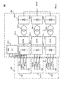
- Multiphase generator conversion system 500 comprises a multiphase generator 510 and a conversion system 520.
- Multiphase generator 510 comprises i number of stators (512-1, 512-2,..., 512-i).
- Each stator includes 3 phase legs [(512-1a, 512-1b, 512-1c), (512-2a, 512-2b, 512-2c),...,(512-ia, 512-ib, 512-ic)].
- Each phase leg may correspond to a winding of the stator and carry a single distinct phase.
- the generator 510 carries 3xi phases. However, in other implementations some or all corresponding phase legs of different stators may be in phase.
- the overall number of phases may be anywhere between 3 and 3xi.
- the phase legs of each stator are connected to a rectification module of a conversion line of the conversion system 520.
- Each conversion line comprises a rectification module, a dc/ac converter, a Low Voltage/Medium Voltage transformer and a diode rectifier.
- the three phase legs of the first stator 512-1 are connected to a rectification module 522-1 of the conversion system 520. Accordingly, the three phase legs of the other stators (512-2 to 512-(i-1)) are connected to rectification modules (522-2 to 522-(i-1)).
- the rectification module 522-1 comprises an active filtering component 522v and a diode rectifier 522d in a shunt configuration.
- Stator 512-1 of Generator 510 comprises 3 phase legs 512-1 a to 512-1 c.
- Rectification module 522-1 comprises VSC 522v and diode rectifier 522d connected in parallel to the phase legs of stator 512-1.
- the VSC of Fig. 5 receives all current measurements from all phase legs of generator 510.
- VSC 522v calculates currents that may be regulated at the input of the diode rectifier 522d of the 1 st conversion line of conversion system 520. This current is calculated so as to mitigate the harmonic emissions of all conversion lines.
- the VSC 522v is not in charge of the power extraction from one of the stators of the generator, as the rectification function is performed by the diode rectifier 522d. Instead, the VSC 522v is in charge of quickly exchanging currents with the conversion line of the stator in which it is connected so as to reduce the harmonic components. Since the VSC 522v is not in charge of any rectification function its size may be limited. Moreover, its function is simply to reduce the harmonic emissions. Therefore, in case the VSC does not work properly, the power extraction from the stator of the wind turbine to the diode rectifier that it is connected to may not be compromised.
- Multiphase generator conversion system 600 comprises a multiphase generator 610 and a conversion system 620.
- Multiphase generator 610 comprises i number of stators (612-1, 612-2,..., 612-i).
- Each stator includes 3 phase legs [(612-1a, 612-1b, 612-1c), (612-2a, 612-2b, 612-2c),...,(612-ia, 612-ib, 612-ic)].
- Each phase leg may correspond to a winding of the stator and carries a single distinct phase.
- the generator 610 carries 3xi phases.
- phase legs of different stators may be in phase. Therefore, in examples according to the invention, the overall number of phases may be anywhere between 3 and 3xi.
- the phase legs of each stator are connected to a rectification module of a conversion line of the conversion system 620.
- Each conversion line comprises a rectification module, a dc/ac converter, a Low Voltage/Medium Voltage transformer and a diode rectifier.
- the three phase legs of the first stator 612-1 are connected to a diode rectifier 622-1 of the conversion system 620.
- the three phase legs of the other stators (612-2 to 612-(i-1)), except the stator 612-i are connected to diode rectifiers (622-2 to 622-(i-1)).
- the phase legs of stator 612-i are connected to active filtering converter 622-i.
- Active filtering converter 622-i is depicted as a VSC. However any type of active filtering converter may be used in place.
- Each of the rectification modules 622-1 to 622-i is connected to a dc/ac converter 624-1 to 624-i, respectively.
- each of the dc/ac converters 624-1 to 624-i is connected to a LV/MV transformer 626-1 to 626-i, respectively.
- each of the LV/MV transformers 626-1 to 626-i is connected to a diode rectifier 628-1 to 628-i, respectively.
- the DC outputs of the diode rectifiers 628-1 to 628-i may be connected to the grid.
- the VSC 622-i comprises a control unit (not shown) that receives current measurements from all the phase legs of all stators. It calculates a current reference, to reduce the machine harmonic content of the machine, to be regulated in its corresponding circuit considering not only the currents that are sensed directly by the VSC (the currents of phase legs 612-ia to 612-ic) but also the currents of the other phase legs,. Therefore, it has the ability to regulate the current flowing its stator e 622-i to mitigate not only the harmonics emitted by the conversion line i, but also the harmonic emissions of all conversion lines. Although only one VSC is shown in Fig. 6 , one skilled in the art may appreciate that more than one VSCs may be used as part of the invention.
- VSC another active filtering converter, or VSC
- a multi-phase generator such as, e.g. a permanent magnet generator of a wind turbine
- VSC another active filtering converter
- the required current to be injected to the windings to affect the flux of the permanent magnet generator may be divided between various active filtering converters, thus avoiding the requirement of oversize additional elements.
- the sizing of the active filtering converters may depend not only on the amount of current required to mitigate the harmonic content but also on the strength of the coupling field of the generator among stators.
- the active filtering converter is used as a full power converter, its sizing may as well be determined by the nominal power of the stator to which it is connected, as the main function of the active filtering converter will be the rectification of the current of the stator.
- FIG. 7 illustrates a generator-conversion system according to yet another example.
- Generator conversion system 700 comprises generator 710, conversion system 720 and switching circuit 730.
- Generator 710 is similar to generators 510 and 610.
- Conversion system 720 comprises i conversion lines. Each conversion line comprises a diode rectifier, a DC/AC converter, a Low to Medium Voltage (LV/MV) transformer and another diode converter.
- the switching circuit comprises a VSC 735, a plurality of switches 732-1 to 732-i and 3 branched lines 733-a to 733-c. Each branched line corresponds to one of the phase legs of the i stators and is connected at the root to the VSC. Each branched line has i number of branches.
- Each branch is connected to a single phase leg.
- Each switch receives a branch of each branched line.
- switch 732-1 receives branches 733-a1, 733-b1 and 733-c1. These branches are each connected to one of the phase legs 712-1a to 712-1c, respectively.
- switch 732-1 When switch 732-1 is closed, then the generator-conversion system 700 functions exactly in the same way as the generator-conversion system 600. However, when switch 732-1 is closed all other switches need to be open.
- the VSC 735 cannot be connected to two different stators at the same time, since it may provoke a short-circuit to the system.
- the VSC may be connected to the stator that is expected to emit the most harmonics. For example, it may connect to the stator where the measured currents are higher. However, not all the time the same stator may generate the highest currents. Therefore, the switching circuit may monitor the current intensity and switch the VSC 735 from stator to stator based on such measurements. Therefore, direct harmonic mitigation may take place at the more harmonic prone stator at any given time. Furthermore, if one stator becomes unavailable, e.g.
- the harmonic mitigation may still be performed from another stator
- Other possible reasons for switching between stators may be differences in the windings of the stators, potential faults that may appear in different phases during the course of life of the generator, or potential differences in the each of the conversion lines due to divergences in the properties of the semiconductors or of the transformers.
- Fig. 8 is a flow diagram of a method of mitigating harmonics in a multi-phase generator-conversion system.
- a first step 810 the values of the currents of the phase legs of all stators are received.
- step 815 the harmonic content present in the phase currents of the m+1 stators of the multi-phase generator are identified.
- a mitigation current based on said current values is calculated. to be applied by the corresponding active filters to mitigate all identified harmonic contents of the stator where the active filter is connected and also of the other stators through the magnetic coupling.
- step 825 the calculated current is applied by the corresponding active filter of the stator where the active filter is connected to directly control its current to vary the magnetic flux of the respective stator. Since the stators are electromagnetic coupled this same current indirectly affects or varies the magnetic flux of the rest of the stators. Thus, it is possible to mitigate the harmonic content from all stators.
Landscapes
- Engineering & Computer Science (AREA)
- Power Engineering (AREA)
- Control Of Eletrric Generators (AREA)
Priority Applications (3)
| Application Number | Priority Date | Filing Date | Title |
|---|---|---|---|
| EP13382510.9A EP2884657B1 (fr) | 2013-12-13 | 2013-12-13 | Atténuation d'harmoniques dans des systèmes générateur-conversion à multiphase |
| PCT/EP2014/077516 WO2015086800A1 (fr) | 2013-12-13 | 2014-12-12 | Atténuation d'harmoniques dans des systèmes de conversion à générateur polyphasé |
| US15/103,882 US9837943B2 (en) | 2013-12-13 | 2014-12-12 | Harmonics mitigation in multiphase generator-conversion systems |
Applications Claiming Priority (1)
| Application Number | Priority Date | Filing Date | Title |
|---|---|---|---|
| EP13382510.9A EP2884657B1 (fr) | 2013-12-13 | 2013-12-13 | Atténuation d'harmoniques dans des systèmes générateur-conversion à multiphase |
Publications (2)
| Publication Number | Publication Date |
|---|---|
| EP2884657A1 true EP2884657A1 (fr) | 2015-06-17 |
| EP2884657B1 EP2884657B1 (fr) | 2016-11-30 |
Family
ID=49916952
Family Applications (1)
| Application Number | Title | Priority Date | Filing Date |
|---|---|---|---|
| EP13382510.9A Active EP2884657B1 (fr) | 2013-12-13 | 2013-12-13 | Atténuation d'harmoniques dans des systèmes générateur-conversion à multiphase |
Country Status (3)
| Country | Link |
|---|---|
| US (1) | US9837943B2 (fr) |
| EP (1) | EP2884657B1 (fr) |
| WO (1) | WO2015086800A1 (fr) |
Cited By (4)
| Publication number | Priority date | Publication date | Assignee | Title |
|---|---|---|---|---|
| EP3223422A1 (fr) * | 2016-03-24 | 2017-09-27 | Siemens Aktiengesellschaft | Agencement de commande d'une machine multi-stators |
| RU2641314C1 (ru) * | 2016-11-08 | 2018-01-17 | федеральное государственное бюджетное образовательное учреждение высшего образования "Национальный исследовательский университет "МЭИ" (ФГБОУ ВО "НИУ "МЭИ") | Устройство генерирования напряжения переменного тока постоянной частоты при переменной частоте вращения привода генератора |
| WO2018115403A1 (fr) * | 2016-12-22 | 2018-06-28 | Abb Schweiz Ag | Système d'entraînement hybride pour véhicule de traction |
| WO2018115404A1 (fr) * | 2016-12-22 | 2018-06-28 | Abb Schweiz Ag | Système d'entraînement hybride pour véhicule de traction |
Families Citing this family (8)
| Publication number | Priority date | Publication date | Assignee | Title |
|---|---|---|---|---|
| WO2014131456A1 (fr) * | 2013-02-28 | 2014-09-04 | Siemens Aktiengesellschaft | Poste de conversion équipé d'un redresseur à diodes |
| GB201521408D0 (en) * | 2015-12-04 | 2016-01-20 | Rolls Royce Plc | Electrical machine component failure detection apparatus and method |
| EP3258594B1 (fr) * | 2016-06-17 | 2022-05-18 | Siemens Gamesa Renewable Energy A/S | Commande d'une machine électrique à réglage multiple |
| DE102017112958A1 (de) * | 2017-06-13 | 2018-12-13 | Wobben Properties Gmbh | Windenergieanlage mit getriebelosem Generator und Generatorfilter |
| US10727769B2 (en) | 2017-09-22 | 2020-07-28 | Hamilton Sundstrand Corporation | Voltage regulation of permanent magnet generator with extended speed range |
| US10601338B2 (en) | 2017-09-25 | 2020-03-24 | Hamilton Sundstrand Corporation | Electric system architecture for a vehicle with multiple load characteristics |
| WO2019157626A1 (fr) * | 2018-02-13 | 2019-08-22 | Envision Energy (Jiangsu) Co., Ltd. | Protection contre la désaimantation d'un générateur à aimants permanents |
| US11231014B2 (en) | 2020-06-22 | 2022-01-25 | General Electric Company | System and method for reducing voltage distortion from an inverter-based resource |
Citations (2)
| Publication number | Priority date | Publication date | Assignee | Title |
|---|---|---|---|---|
| US20100133816A1 (en) * | 2009-06-30 | 2010-06-03 | Mehdi Abolhassani | Power Converter For Use With Wind Generator |
| EP2479882A2 (fr) * | 2011-01-19 | 2012-07-25 | Vacon Oyj | Appareil de transfert d'une puissance électrique entre un réseau à tension alternative et une machine électrique tournante polyphasée |
Family Cites Families (8)
| Publication number | Priority date | Publication date | Assignee | Title |
|---|---|---|---|---|
| US6272025B1 (en) * | 1999-10-01 | 2001-08-07 | Online Power Supply, Inc. | Individual for distributed non-saturated magnetic element(s) (referenced herein as NSME) power converters |
| US6952355B2 (en) * | 2002-07-22 | 2005-10-04 | Ops Power Llc | Two-stage converter using low permeability magnetics |
| US7417875B2 (en) * | 2005-02-08 | 2008-08-26 | Coldwatt, Inc. | Power converter employing integrated magnetics with a current multiplier rectifier and method of operating the same |
| US8363439B2 (en) * | 2008-04-22 | 2013-01-29 | Flextronics Ap, Llc | Efficiency improvement in power factor correction |
| RU2519636C2 (ru) * | 2008-09-22 | 2014-06-20 | Сименс Индастри, Инк. | Системы, устройства и способы для управления реактивной мощностью |
| US9628016B2 (en) * | 2011-04-14 | 2017-04-18 | Craig Lamascus | Electrical apparatus and control system |
| EP2629386B1 (fr) * | 2012-02-16 | 2018-01-10 | GE Renewable Technologies | Procédé permettant d'éviter l'instabilité de tension dans un réseau électrique d'un parc éolien en mer |
| US9401634B2 (en) * | 2012-10-04 | 2016-07-26 | Power Integrations, Inc. | Saturation prevention in an energy transfer element of a power converter |
-
2013
- 2013-12-13 EP EP13382510.9A patent/EP2884657B1/fr active Active
-
2014
- 2014-12-12 WO PCT/EP2014/077516 patent/WO2015086800A1/fr active Application Filing
- 2014-12-12 US US15/103,882 patent/US9837943B2/en active Active
Patent Citations (2)
| Publication number | Priority date | Publication date | Assignee | Title |
|---|---|---|---|---|
| US20100133816A1 (en) * | 2009-06-30 | 2010-06-03 | Mehdi Abolhassani | Power Converter For Use With Wind Generator |
| EP2479882A2 (fr) * | 2011-01-19 | 2012-07-25 | Vacon Oyj | Appareil de transfert d'une puissance électrique entre un réseau à tension alternative et une machine électrique tournante polyphasée |
Cited By (6)
| Publication number | Priority date | Publication date | Assignee | Title |
|---|---|---|---|---|
| EP3223422A1 (fr) * | 2016-03-24 | 2017-09-27 | Siemens Aktiengesellschaft | Agencement de commande d'une machine multi-stators |
| CN107231105A (zh) * | 2016-03-24 | 2017-10-03 | 西门子公司 | 多定子机器的控制布置 |
| US10389284B2 (en) | 2016-03-24 | 2019-08-20 | Siemens Gamesa Renewable Energy A/S | Control arrangement of a multi-stator machine |
| RU2641314C1 (ru) * | 2016-11-08 | 2018-01-17 | федеральное государственное бюджетное образовательное учреждение высшего образования "Национальный исследовательский университет "МЭИ" (ФГБОУ ВО "НИУ "МЭИ") | Устройство генерирования напряжения переменного тока постоянной частоты при переменной частоте вращения привода генератора |
| WO2018115403A1 (fr) * | 2016-12-22 | 2018-06-28 | Abb Schweiz Ag | Système d'entraînement hybride pour véhicule de traction |
| WO2018115404A1 (fr) * | 2016-12-22 | 2018-06-28 | Abb Schweiz Ag | Système d'entraînement hybride pour véhicule de traction |
Also Published As
| Publication number | Publication date |
|---|---|
| WO2015086800A1 (fr) | 2015-06-18 |
| US20160322924A1 (en) | 2016-11-03 |
| US9837943B2 (en) | 2017-12-05 |
| EP2884657B1 (fr) | 2016-11-30 |
Similar Documents
| Publication | Publication Date | Title |
|---|---|---|
| EP2884657B1 (fr) | Atténuation d'harmoniques dans des systèmes générateur-conversion à multiphase | |
| CN103181052B (zh) | 用于稳定供电网的方法 | |
| US9853574B2 (en) | Voltage source converter | |
| EP2429073B1 (fr) | Convertisseurs électriques | |
| US9515565B2 (en) | Hybrid high voltage direct current converter systems | |
| EP2760123A2 (fr) | Convertisseur multi-cellules pont complet en cascade avec equilibrage transformateur de puissance entre les cellules dans chaque niveau de tension | |
| US9831759B2 (en) | Voltage source converter | |
| EP2566030A2 (fr) | Système et procédé de conversion dýénergie | |
| EP3435531A1 (fr) | Dispositif de conversion de puissance électrique | |
| KR20180134329A (ko) | 전력 분배망 및 전력 분배 방법 | |
| WO2015030922A1 (fr) | Procédés et systèmes pour génération cc électrique | |
| EP2953228A1 (fr) | Dispositif et procédé de raccordement d'un générateur de puissance électrique pour un système de transmission HVDC | |
| EP3361619B1 (fr) | Convertisseur de source de tension | |
| KR101465372B1 (ko) | 3상 교류 전력망에 전기 에너지를 공급하는 방법 | |
| Li et al. | Distributed generation grid-connected converter testing device based on cascaded H-bridge topology | |
| US7327134B1 (en) | Method and system for transformer control | |
| Prasai et al. | Compact dynamic phase angle regulator for power flow control | |
| Grainger et al. | Analysis of an offshore medium voltage DC microgrid environment—Part I: Power sharing controller design | |
| Modi et al. | F-lms adaptive filter based control algorithm with power management strategy for grid integrated rooftop spv-bes system | |
| Plummer | Assymmetry in distribution systems: causes, harmful effects and remedies | |
| EP3301775A1 (fr) | Système de convertisseur pour compensation et équilibrage de charge connecté à un réseau de distribution d'énergie électrique | |
| CN115296310A (zh) | 用于三相电力系统的具有有功功率注入器的零序电流平衡器 | |
| Andrews et al. | Decarbonizing turbine powered oil and gas processes with electrical adjustable speed drive systems | |
| Rahman et al. | Stability improvement of simultaneous AC-DC power transmission system | |
| Hoevenaars et al. | Rightsizing generators through harmonic mitigation realizes energy, emissions and infrastructure reductions |
Legal Events
| Date | Code | Title | Description |
|---|---|---|---|
| PUAI | Public reference made under article 153(3) epc to a published international application that has entered the european phase |
Free format text: ORIGINAL CODE: 0009012 |
|
| 17P | Request for examination filed |
Effective date: 20131213 |
|
| AK | Designated contracting states |
Kind code of ref document: A1 Designated state(s): AL AT BE BG CH CY CZ DE DK EE ES FI FR GB GR HR HU IE IS IT LI LT LU LV MC MK MT NL NO PL PT RO RS SE SI SK SM TR |
|
| AX | Request for extension of the european patent |
Extension state: BA ME |
|
| R17P | Request for examination filed (corrected) |
Effective date: 20151217 |
|
| RBV | Designated contracting states (corrected) |
Designated state(s): AL AT BE BG CH CY CZ DE DK EE ES FI FR GB GR HR HU IE IS IT LI LT LU LV MC MK MT NL NO PL PT RO RS SE SI SK SM TR |
|
| REG | Reference to a national code |
Ref country code: DE Ref legal event code: R079 Ref document number: 602013014674 Country of ref document: DE Free format text: PREVIOUS MAIN CLASS: H02P0009100000 Ipc: H02P0021240000 |
|
| GRAP | Despatch of communication of intention to grant a patent |
Free format text: ORIGINAL CODE: EPIDOSNIGR1 |
|
| RIC1 | Information provided on ipc code assigned before grant |
Ipc: H02P 9/10 20060101ALI20160510BHEP Ipc: H02P 21/24 20160101AFI20160510BHEP Ipc: H02P 9/30 20060101ALI20160510BHEP |
|
| INTG | Intention to grant announced |
Effective date: 20160610 |
|
| GRAS | Grant fee paid |
Free format text: ORIGINAL CODE: EPIDOSNIGR3 |
|
| GRAA | (expected) grant |
Free format text: ORIGINAL CODE: 0009210 |
|
| AK | Designated contracting states |
Kind code of ref document: B1 Designated state(s): AL AT BE BG CH CY CZ DE DK EE ES FI FR GB GR HR HU IE IS IT LI LT LU LV MC MK MT NL NO PL PT RO RS SE SI SK SM TR |
|
| REG | Reference to a national code |
Ref country code: CH Ref legal event code: EP Ref country code: GB Ref legal event code: FG4D |
|
| REG | Reference to a national code |
Ref country code: AT Ref legal event code: REF Ref document number: 850663 Country of ref document: AT Kind code of ref document: T Effective date: 20161215 |
|
| REG | Reference to a national code |
Ref country code: FR Ref legal event code: PLFP Year of fee payment: 4 |
|
| REG | Reference to a national code |
Ref country code: IE Ref legal event code: FG4D |
|
| REG | Reference to a national code |
Ref country code: DE Ref legal event code: R096 Ref document number: 602013014674 Country of ref document: DE |
|
| PG25 | Lapsed in a contracting state [announced via postgrant information from national office to epo] |
Ref country code: LV Free format text: LAPSE BECAUSE OF FAILURE TO SUBMIT A TRANSLATION OF THE DESCRIPTION OR TO PAY THE FEE WITHIN THE PRESCRIBED TIME-LIMIT Effective date: 20161130 |
|
| REG | Reference to a national code |
Ref country code: LT Ref legal event code: MG4D |
|
| REG | Reference to a national code |
Ref country code: NL Ref legal event code: MP Effective date: 20161130 |
|
| REG | Reference to a national code |
Ref country code: AT Ref legal event code: MK05 Ref document number: 850663 Country of ref document: AT Kind code of ref document: T Effective date: 20161130 |
|
| PG25 | Lapsed in a contracting state [announced via postgrant information from national office to epo] |
Ref country code: SE Free format text: LAPSE BECAUSE OF FAILURE TO SUBMIT A TRANSLATION OF THE DESCRIPTION OR TO PAY THE FEE WITHIN THE PRESCRIBED TIME-LIMIT Effective date: 20161130 Ref country code: LT Free format text: LAPSE BECAUSE OF FAILURE TO SUBMIT A TRANSLATION OF THE DESCRIPTION OR TO PAY THE FEE WITHIN THE PRESCRIBED TIME-LIMIT Effective date: 20161130 Ref country code: GR Free format text: LAPSE BECAUSE OF FAILURE TO SUBMIT A TRANSLATION OF THE DESCRIPTION OR TO PAY THE FEE WITHIN THE PRESCRIBED TIME-LIMIT Effective date: 20170301 Ref country code: NO Free format text: LAPSE BECAUSE OF FAILURE TO SUBMIT A TRANSLATION OF THE DESCRIPTION OR TO PAY THE FEE WITHIN THE PRESCRIBED TIME-LIMIT Effective date: 20170228 |
|
| PG25 | Lapsed in a contracting state [announced via postgrant information from national office to epo] |
Ref country code: PL Free format text: LAPSE BECAUSE OF FAILURE TO SUBMIT A TRANSLATION OF THE DESCRIPTION OR TO PAY THE FEE WITHIN THE PRESCRIBED TIME-LIMIT Effective date: 20161130 Ref country code: RS Free format text: LAPSE BECAUSE OF FAILURE TO SUBMIT A TRANSLATION OF THE DESCRIPTION OR TO PAY THE FEE WITHIN THE PRESCRIBED TIME-LIMIT Effective date: 20161130 Ref country code: AT Free format text: LAPSE BECAUSE OF FAILURE TO SUBMIT A TRANSLATION OF THE DESCRIPTION OR TO PAY THE FEE WITHIN THE PRESCRIBED TIME-LIMIT Effective date: 20161130 Ref country code: ES Free format text: LAPSE BECAUSE OF FAILURE TO SUBMIT A TRANSLATION OF THE DESCRIPTION OR TO PAY THE FEE WITHIN THE PRESCRIBED TIME-LIMIT Effective date: 20161130 Ref country code: PT Free format text: LAPSE BECAUSE OF FAILURE TO SUBMIT A TRANSLATION OF THE DESCRIPTION OR TO PAY THE FEE WITHIN THE PRESCRIBED TIME-LIMIT Effective date: 20170330 Ref country code: HR Free format text: LAPSE BECAUSE OF FAILURE TO SUBMIT A TRANSLATION OF THE DESCRIPTION OR TO PAY THE FEE WITHIN THE PRESCRIBED TIME-LIMIT Effective date: 20161130 Ref country code: BE Free format text: LAPSE BECAUSE OF NON-PAYMENT OF DUE FEES Effective date: 20161231 Ref country code: FI Free format text: LAPSE BECAUSE OF FAILURE TO SUBMIT A TRANSLATION OF THE DESCRIPTION OR TO PAY THE FEE WITHIN THE PRESCRIBED TIME-LIMIT Effective date: 20161130 |
|
| PG25 | Lapsed in a contracting state [announced via postgrant information from national office to epo] |
Ref country code: NL Free format text: LAPSE BECAUSE OF FAILURE TO SUBMIT A TRANSLATION OF THE DESCRIPTION OR TO PAY THE FEE WITHIN THE PRESCRIBED TIME-LIMIT Effective date: 20161130 |
|
| PG25 | Lapsed in a contracting state [announced via postgrant information from national office to epo] |
Ref country code: CZ Free format text: LAPSE BECAUSE OF FAILURE TO SUBMIT A TRANSLATION OF THE DESCRIPTION OR TO PAY THE FEE WITHIN THE PRESCRIBED TIME-LIMIT Effective date: 20161130 Ref country code: RO Free format text: LAPSE BECAUSE OF FAILURE TO SUBMIT A TRANSLATION OF THE DESCRIPTION OR TO PAY THE FEE WITHIN THE PRESCRIBED TIME-LIMIT Effective date: 20161130 Ref country code: SK Free format text: LAPSE BECAUSE OF FAILURE TO SUBMIT A TRANSLATION OF THE DESCRIPTION OR TO PAY THE FEE WITHIN THE PRESCRIBED TIME-LIMIT Effective date: 20161130 Ref country code: EE Free format text: LAPSE BECAUSE OF FAILURE TO SUBMIT A TRANSLATION OF THE DESCRIPTION OR TO PAY THE FEE WITHIN THE PRESCRIBED TIME-LIMIT Effective date: 20161130 Ref country code: DK Free format text: LAPSE BECAUSE OF FAILURE TO SUBMIT A TRANSLATION OF THE DESCRIPTION OR TO PAY THE FEE WITHIN THE PRESCRIBED TIME-LIMIT Effective date: 20161130 |
|
| REG | Reference to a national code |
Ref country code: CH Ref legal event code: PL |
|
| PG25 | Lapsed in a contracting state [announced via postgrant information from national office to epo] |
Ref country code: SM Free format text: LAPSE BECAUSE OF FAILURE TO SUBMIT A TRANSLATION OF THE DESCRIPTION OR TO PAY THE FEE WITHIN THE PRESCRIBED TIME-LIMIT Effective date: 20161130 Ref country code: BE Free format text: LAPSE BECAUSE OF FAILURE TO SUBMIT A TRANSLATION OF THE DESCRIPTION OR TO PAY THE FEE WITHIN THE PRESCRIBED TIME-LIMIT Effective date: 20161130 Ref country code: IT Free format text: LAPSE BECAUSE OF FAILURE TO SUBMIT A TRANSLATION OF THE DESCRIPTION OR TO PAY THE FEE WITHIN THE PRESCRIBED TIME-LIMIT Effective date: 20161130 Ref country code: BG Free format text: LAPSE BECAUSE OF FAILURE TO SUBMIT A TRANSLATION OF THE DESCRIPTION OR TO PAY THE FEE WITHIN THE PRESCRIBED TIME-LIMIT Effective date: 20170228 |
|
| REG | Reference to a national code |
Ref country code: DE Ref legal event code: R097 Ref document number: 602013014674 Country of ref document: DE |
|
| PG25 | Lapsed in a contracting state [announced via postgrant information from national office to epo] |
Ref country code: MC Free format text: LAPSE BECAUSE OF FAILURE TO SUBMIT A TRANSLATION OF THE DESCRIPTION OR TO PAY THE FEE WITHIN THE PRESCRIBED TIME-LIMIT Effective date: 20161130 |
|
| REG | Reference to a national code |
Ref country code: IE Ref legal event code: MM4A |
|
| PLBE | No opposition filed within time limit |
Free format text: ORIGINAL CODE: 0009261 |
|
| STAA | Information on the status of an ep patent application or granted ep patent |
Free format text: STATUS: NO OPPOSITION FILED WITHIN TIME LIMIT |
|
| PG25 | Lapsed in a contracting state [announced via postgrant information from national office to epo] |
Ref country code: LU Free format text: LAPSE BECAUSE OF NON-PAYMENT OF DUE FEES Effective date: 20161213 Ref country code: CH Free format text: LAPSE BECAUSE OF NON-PAYMENT OF DUE FEES Effective date: 20161231 Ref country code: LI Free format text: LAPSE BECAUSE OF NON-PAYMENT OF DUE FEES Effective date: 20161231 |
|
| 26N | No opposition filed |
Effective date: 20170831 |
|
| PG25 | Lapsed in a contracting state [announced via postgrant information from national office to epo] |
Ref country code: SI Free format text: LAPSE BECAUSE OF FAILURE TO SUBMIT A TRANSLATION OF THE DESCRIPTION OR TO PAY THE FEE WITHIN THE PRESCRIBED TIME-LIMIT Effective date: 20161130 Ref country code: IE Free format text: LAPSE BECAUSE OF NON-PAYMENT OF DUE FEES Effective date: 20161213 |
|
| REG | Reference to a national code |
Ref country code: DE Ref legal event code: R081 Ref document number: 602013014674 Country of ref document: DE Owner name: GE RENEWABLE TECHNOLOGIES WIND B.V., NL Free format text: FORMER OWNER: ALSTOM RENOVABLES ESPANA, S.L., BARCELONA, ES |
|
| REG | Reference to a national code |
Ref country code: FR Ref legal event code: PLFP Year of fee payment: 5 |
|
| REG | Reference to a national code |
Ref country code: FR Ref legal event code: CD Owner name: GE RENEWABLE TECHNOLOGIES WIND B.V., NL Effective date: 20180219 Ref country code: FR Ref legal event code: TP Owner name: GE RENEWABLE TECHNOLOGIES WIND B.V., NL Effective date: 20180219 |
|
| PG25 | Lapsed in a contracting state [announced via postgrant information from national office to epo] |
Ref country code: HU Free format text: LAPSE BECAUSE OF FAILURE TO SUBMIT A TRANSLATION OF THE DESCRIPTION OR TO PAY THE FEE WITHIN THE PRESCRIBED TIME-LIMIT; INVALID AB INITIO Effective date: 20131213 |
|
| PG25 | Lapsed in a contracting state [announced via postgrant information from national office to epo] |
Ref country code: CY Free format text: LAPSE BECAUSE OF FAILURE TO SUBMIT A TRANSLATION OF THE DESCRIPTION OR TO PAY THE FEE WITHIN THE PRESCRIBED TIME-LIMIT Effective date: 20161130 Ref country code: MK Free format text: LAPSE BECAUSE OF FAILURE TO SUBMIT A TRANSLATION OF THE DESCRIPTION OR TO PAY THE FEE WITHIN THE PRESCRIBED TIME-LIMIT Effective date: 20161130 Ref country code: IS Free format text: LAPSE BECAUSE OF FAILURE TO SUBMIT A TRANSLATION OF THE DESCRIPTION OR TO PAY THE FEE WITHIN THE PRESCRIBED TIME-LIMIT Effective date: 20161130 |
|
| GBPC | Gb: european patent ceased through non-payment of renewal fee |
Effective date: 20171213 |
|
| PG25 | Lapsed in a contracting state [announced via postgrant information from national office to epo] |
Ref country code: MT Free format text: LAPSE BECAUSE OF NON-PAYMENT OF DUE FEES Effective date: 20161213 |
|
| PG25 | Lapsed in a contracting state [announced via postgrant information from national office to epo] |
Ref country code: TR Free format text: LAPSE BECAUSE OF FAILURE TO SUBMIT A TRANSLATION OF THE DESCRIPTION OR TO PAY THE FEE WITHIN THE PRESCRIBED TIME-LIMIT Effective date: 20161130 |
|
| PG25 | Lapsed in a contracting state [announced via postgrant information from national office to epo] |
Ref country code: GB Free format text: LAPSE BECAUSE OF NON-PAYMENT OF DUE FEES Effective date: 20171213 |
|
| PG25 | Lapsed in a contracting state [announced via postgrant information from national office to epo] |
Ref country code: AL Free format text: LAPSE BECAUSE OF FAILURE TO SUBMIT A TRANSLATION OF THE DESCRIPTION OR TO PAY THE FEE WITHIN THE PRESCRIBED TIME-LIMIT Effective date: 20161130 |
|
| P01 | Opt-out of the competence of the unified patent court (upc) registered |
Effective date: 20230529 |
|
| PGFP | Annual fee paid to national office [announced via postgrant information from national office to epo] |
Ref country code: FR Payment date: 20231122 Year of fee payment: 11 Ref country code: DE Payment date: 20231121 Year of fee payment: 11 |