EP2884559A1 - Rechargeable battery and manufacturing method of the same - Google Patents
Rechargeable battery and manufacturing method of the same Download PDFInfo
- Publication number
- EP2884559A1 EP2884559A1 EP14197013.7A EP14197013A EP2884559A1 EP 2884559 A1 EP2884559 A1 EP 2884559A1 EP 14197013 A EP14197013 A EP 14197013A EP 2884559 A1 EP2884559 A1 EP 2884559A1
- Authority
- EP
- European Patent Office
- Prior art keywords
- electrodes
- electrode
- rechargeable battery
- separator
- pouch
- Prior art date
- Legal status (The legal status is an assumption and is not a legal conclusion. Google has not performed a legal analysis and makes no representation as to the accuracy of the status listed.)
- Ceased
Links
Images



Classifications
-
- H—ELECTRICITY
- H01—ELECTRIC ELEMENTS
- H01M—PROCESSES OR MEANS, e.g. BATTERIES, FOR THE DIRECT CONVERSION OF CHEMICAL ENERGY INTO ELECTRICAL ENERGY
- H01M10/00—Secondary cells; Manufacture thereof
- H01M10/04—Construction or manufacture in general
- H01M10/045—Cells or batteries with folded plate-like electrodes
-
- H—ELECTRICITY
- H01—ELECTRIC ELEMENTS
- H01M—PROCESSES OR MEANS, e.g. BATTERIES, FOR THE DIRECT CONVERSION OF CHEMICAL ENERGY INTO ELECTRICAL ENERGY
- H01M4/00—Electrodes
- H01M4/02—Electrodes composed of, or comprising, active material
- H01M4/04—Processes of manufacture in general
- H01M4/043—Processes of manufacture in general involving compressing or compaction
- H01M4/0433—Molding
-
- H—ELECTRICITY
- H01—ELECTRIC ELEMENTS
- H01M—PROCESSES OR MEANS, e.g. BATTERIES, FOR THE DIRECT CONVERSION OF CHEMICAL ENERGY INTO ELECTRICAL ENERGY
- H01M10/00—Secondary cells; Manufacture thereof
- H01M10/04—Construction or manufacture in general
-
- H—ELECTRICITY
- H01—ELECTRIC ELEMENTS
- H01M—PROCESSES OR MEANS, e.g. BATTERIES, FOR THE DIRECT CONVERSION OF CHEMICAL ENERGY INTO ELECTRICAL ENERGY
- H01M10/00—Secondary cells; Manufacture thereof
- H01M10/04—Construction or manufacture in general
- H01M10/0436—Small-sized flat cells or batteries for portable equipment
-
- H—ELECTRICITY
- H01—ELECTRIC ELEMENTS
- H01M—PROCESSES OR MEANS, e.g. BATTERIES, FOR THE DIRECT CONVERSION OF CHEMICAL ENERGY INTO ELECTRICAL ENERGY
- H01M10/00—Secondary cells; Manufacture thereof
- H01M10/05—Accumulators with non-aqueous electrolyte
- H01M10/058—Construction or manufacture
- H01M10/0583—Construction or manufacture of accumulators with folded construction elements except wound ones, i.e. folded positive or negative electrodes or separators, e.g. with "Z"-shaped electrodes or separators
-
- H—ELECTRICITY
- H01—ELECTRIC ELEMENTS
- H01M—PROCESSES OR MEANS, e.g. BATTERIES, FOR THE DIRECT CONVERSION OF CHEMICAL ENERGY INTO ELECTRICAL ENERGY
- H01M4/00—Electrodes
- H01M4/02—Electrodes composed of, or comprising, active material
- H01M4/04—Processes of manufacture in general
-
- H—ELECTRICITY
- H01—ELECTRIC ELEMENTS
- H01M—PROCESSES OR MEANS, e.g. BATTERIES, FOR THE DIRECT CONVERSION OF CHEMICAL ENERGY INTO ELECTRICAL ENERGY
- H01M4/00—Electrodes
- H01M4/02—Electrodes composed of, or comprising, active material
- H01M4/64—Carriers or collectors
- H01M4/70—Carriers or collectors characterised by shape or form
- H01M4/78—Shapes other than plane or cylindrical, e.g. helical
-
- H—ELECTRICITY
- H01—ELECTRIC ELEMENTS
- H01M—PROCESSES OR MEANS, e.g. BATTERIES, FOR THE DIRECT CONVERSION OF CHEMICAL ENERGY INTO ELECTRICAL ENERGY
- H01M4/00—Electrodes
- H01M4/02—Electrodes composed of, or comprising, active material
- H01M4/64—Carriers or collectors
- H01M4/70—Carriers or collectors characterised by shape or form
- H01M4/80—Porous plates, e.g. sintered carriers
- H01M4/806—Nonwoven fibrous fabric containing only fibres
-
- H—ELECTRICITY
- H01—ELECTRIC ELEMENTS
- H01M—PROCESSES OR MEANS, e.g. BATTERIES, FOR THE DIRECT CONVERSION OF CHEMICAL ENERGY INTO ELECTRICAL ENERGY
- H01M50/00—Constructional details or processes of manufacture of the non-active parts of electrochemical cells other than fuel cells, e.g. hybrid cells
- H01M50/10—Primary casings; Jackets or wrappings
- H01M50/102—Primary casings; Jackets or wrappings characterised by their shape or physical structure
- H01M50/105—Pouches or flexible bags
-
- H—ELECTRICITY
- H01—ELECTRIC ELEMENTS
- H01M—PROCESSES OR MEANS, e.g. BATTERIES, FOR THE DIRECT CONVERSION OF CHEMICAL ENERGY INTO ELECTRICAL ENERGY
- H01M50/00—Constructional details or processes of manufacture of the non-active parts of electrochemical cells other than fuel cells, e.g. hybrid cells
- H01M50/10—Primary casings; Jackets or wrappings
- H01M50/116—Primary casings; Jackets or wrappings characterised by the material
- H01M50/124—Primary casings; Jackets or wrappings characterised by the material having a layered structure
-
- H—ELECTRICITY
- H01—ELECTRIC ELEMENTS
- H01M—PROCESSES OR MEANS, e.g. BATTERIES, FOR THE DIRECT CONVERSION OF CHEMICAL ENERGY INTO ELECTRICAL ENERGY
- H01M50/00—Constructional details or processes of manufacture of the non-active parts of electrochemical cells other than fuel cells, e.g. hybrid cells
- H01M50/10—Primary casings; Jackets or wrappings
- H01M50/131—Primary casings; Jackets or wrappings characterised by physical properties, e.g. gas permeability, size or heat resistance
- H01M50/136—Flexibility or foldability
-
- H—ELECTRICITY
- H01—ELECTRIC ELEMENTS
- H01M—PROCESSES OR MEANS, e.g. BATTERIES, FOR THE DIRECT CONVERSION OF CHEMICAL ENERGY INTO ELECTRICAL ENERGY
- H01M50/00—Constructional details or processes of manufacture of the non-active parts of electrochemical cells other than fuel cells, e.g. hybrid cells
- H01M50/40—Separators; Membranes; Diaphragms; Spacing elements inside cells
- H01M50/46—Separators, membranes or diaphragms characterised by their combination with electrodes
-
- H—ELECTRICITY
- H01—ELECTRIC ELEMENTS
- H01M—PROCESSES OR MEANS, e.g. BATTERIES, FOR THE DIRECT CONVERSION OF CHEMICAL ENERGY INTO ELECTRICAL ENERGY
- H01M50/00—Constructional details or processes of manufacture of the non-active parts of electrochemical cells other than fuel cells, e.g. hybrid cells
- H01M50/50—Current conducting connections for cells or batteries
- H01M50/543—Terminals
- H01M50/547—Terminals characterised by the disposition of the terminals on the cells
- H01M50/55—Terminals characterised by the disposition of the terminals on the cells on the same side of the cell
-
- H—ELECTRICITY
- H01—ELECTRIC ELEMENTS
- H01M—PROCESSES OR MEANS, e.g. BATTERIES, FOR THE DIRECT CONVERSION OF CHEMICAL ENERGY INTO ELECTRICAL ENERGY
- H01M50/00—Constructional details or processes of manufacture of the non-active parts of electrochemical cells other than fuel cells, e.g. hybrid cells
- H01M50/50—Current conducting connections for cells or batteries
- H01M50/543—Terminals
- H01M50/552—Terminals characterised by their shape
- H01M50/553—Terminals adapted for prismatic, pouch or rectangular cells
- H01M50/557—Plate-shaped terminals
-
- H—ELECTRICITY
- H01—ELECTRIC ELEMENTS
- H01M—PROCESSES OR MEANS, e.g. BATTERIES, FOR THE DIRECT CONVERSION OF CHEMICAL ENERGY INTO ELECTRICAL ENERGY
- H01M4/00—Electrodes
- H01M4/02—Electrodes composed of, or comprising, active material
- H01M2004/025—Electrodes composed of, or comprising, active material with shapes other than plane or cylindrical
-
- H—ELECTRICITY
- H01—ELECTRIC ELEMENTS
- H01M—PROCESSES OR MEANS, e.g. BATTERIES, FOR THE DIRECT CONVERSION OF CHEMICAL ENERGY INTO ELECTRICAL ENERGY
- H01M4/00—Electrodes
- H01M4/02—Electrodes composed of, or comprising, active material
- H01M4/64—Carriers or collectors
- H01M4/66—Selection of materials
- H01M4/661—Metal or alloys, e.g. alloy coatings
-
- H—ELECTRICITY
- H01—ELECTRIC ELEMENTS
- H01M—PROCESSES OR MEANS, e.g. BATTERIES, FOR THE DIRECT CONVERSION OF CHEMICAL ENERGY INTO ELECTRICAL ENERGY
- H01M50/00—Constructional details or processes of manufacture of the non-active parts of electrochemical cells other than fuel cells, e.g. hybrid cells
- H01M50/10—Primary casings; Jackets or wrappings
- H01M50/116—Primary casings; Jackets or wrappings characterised by the material
- H01M50/117—Inorganic material
- H01M50/119—Metals
-
- H—ELECTRICITY
- H01—ELECTRIC ELEMENTS
- H01M—PROCESSES OR MEANS, e.g. BATTERIES, FOR THE DIRECT CONVERSION OF CHEMICAL ENERGY INTO ELECTRICAL ENERGY
- H01M50/00—Constructional details or processes of manufacture of the non-active parts of electrochemical cells other than fuel cells, e.g. hybrid cells
- H01M50/10—Primary casings; Jackets or wrappings
- H01M50/116—Primary casings; Jackets or wrappings characterised by the material
- H01M50/121—Organic material
-
- H—ELECTRICITY
- H01—ELECTRIC ELEMENTS
- H01M—PROCESSES OR MEANS, e.g. BATTERIES, FOR THE DIRECT CONVERSION OF CHEMICAL ENERGY INTO ELECTRICAL ENERGY
- H01M50/00—Constructional details or processes of manufacture of the non-active parts of electrochemical cells other than fuel cells, e.g. hybrid cells
- H01M50/10—Primary casings; Jackets or wrappings
- H01M50/116—Primary casings; Jackets or wrappings characterised by the material
- H01M50/124—Primary casings; Jackets or wrappings characterised by the material having a layered structure
- H01M50/126—Primary casings; Jackets or wrappings characterised by the material having a layered structure comprising three or more layers
- H01M50/129—Primary casings; Jackets or wrappings characterised by the material having a layered structure comprising three or more layers with two or more layers of only organic material
-
- Y—GENERAL TAGGING OF NEW TECHNOLOGICAL DEVELOPMENTS; GENERAL TAGGING OF CROSS-SECTIONAL TECHNOLOGIES SPANNING OVER SEVERAL SECTIONS OF THE IPC; TECHNICAL SUBJECTS COVERED BY FORMER USPC CROSS-REFERENCE ART COLLECTIONS [XRACs] AND DIGESTS
- Y02—TECHNOLOGIES OR APPLICATIONS FOR MITIGATION OR ADAPTATION AGAINST CLIMATE CHANGE
- Y02E—REDUCTION OF GREENHOUSE GAS [GHG] EMISSIONS, RELATED TO ENERGY GENERATION, TRANSMISSION OR DISTRIBUTION
- Y02E60/00—Enabling technologies; Technologies with a potential or indirect contribution to GHG emissions mitigation
- Y02E60/10—Energy storage using batteries
-
- Y—GENERAL TAGGING OF NEW TECHNOLOGICAL DEVELOPMENTS; GENERAL TAGGING OF CROSS-SECTIONAL TECHNOLOGIES SPANNING OVER SEVERAL SECTIONS OF THE IPC; TECHNICAL SUBJECTS COVERED BY FORMER USPC CROSS-REFERENCE ART COLLECTIONS [XRACs] AND DIGESTS
- Y02—TECHNOLOGIES OR APPLICATIONS FOR MITIGATION OR ADAPTATION AGAINST CLIMATE CHANGE
- Y02P—CLIMATE CHANGE MITIGATION TECHNOLOGIES IN THE PRODUCTION OR PROCESSING OF GOODS
- Y02P70/00—Climate change mitigation technologies in the production process for final industrial or consumer products
- Y02P70/50—Manufacturing or production processes characterised by the final manufactured product
-
- Y—GENERAL TAGGING OF NEW TECHNOLOGICAL DEVELOPMENTS; GENERAL TAGGING OF CROSS-SECTIONAL TECHNOLOGIES SPANNING OVER SEVERAL SECTIONS OF THE IPC; TECHNICAL SUBJECTS COVERED BY FORMER USPC CROSS-REFERENCE ART COLLECTIONS [XRACs] AND DIGESTS
- Y10—TECHNICAL SUBJECTS COVERED BY FORMER USPC
- Y10T—TECHNICAL SUBJECTS COVERED BY FORMER US CLASSIFICATION
- Y10T29/00—Metal working
- Y10T29/49—Method of mechanical manufacture
- Y10T29/49002—Electrical device making
- Y10T29/49108—Electric battery cell making
-
- Y—GENERAL TAGGING OF NEW TECHNOLOGICAL DEVELOPMENTS; GENERAL TAGGING OF CROSS-SECTIONAL TECHNOLOGIES SPANNING OVER SEVERAL SECTIONS OF THE IPC; TECHNICAL SUBJECTS COVERED BY FORMER USPC CROSS-REFERENCE ART COLLECTIONS [XRACs] AND DIGESTS
- Y10—TECHNICAL SUBJECTS COVERED BY FORMER USPC
- Y10T—TECHNICAL SUBJECTS COVERED BY FORMER US CLASSIFICATION
- Y10T29/00—Metal working
- Y10T29/49—Method of mechanical manufacture
- Y10T29/49002—Electrical device making
- Y10T29/49108—Electric battery cell making
- Y10T29/49114—Electric battery cell making including adhesively bonding
Definitions
- aspects of embodiments according to the present disclosure relate generally to a rechargeable battery that may be manufactured and used in various three-dimensional shapes, and a manufacturing method of the same.
- a rechargeable battery is a battery that is configured to repeatedly perform charging and discharging, unlike a primary battery, which is not designed to be repeatedly charged and discharged.
- a small-capacity rechargeable battery is used in small portable electronic devices, such as a mobile phone, a tablet computer, a laptop computer, and a camcorder.
- a large-capacity rechargeable battery is used as a power supply for driving a motor, for an electric bicycle, a scooter, an electric vehicle, a fork lift, and the like.
- aspects of embodiments of the described technology are directed toward a rechargeable battery that may be manufactured and used in various three-dimensional shapes. Further, aspects of embodiments of the present invention are directed toward a method for manufacturing the rechargeable battery.
- An embodiment of a rechargeable battery includes: an electrode assembly including a pair of electrodes on respective surfaces of a separator, and a pair of lead tabs extending from the pair of electrodes; and a pouch receiving the electrode assembly and having the lead tabs protruding out to one side.
- Each of the electrodes includes a first bending part including a molded plate including a mixture of active material particles and a metal fiber yarn of a current collector.
- the pouch includes a second bending part superimposed on the electrode in parallel and includes a molded sheet having a shape corresponding to that of the first bending part.
- the separator may be adhesive.
- the pair of electrodes and the separator may be stacked together. A thickness of each of the pair of electrodes may be the same.
- the pouch may include: a concave member having a concave part receiving the electrode assembly to at least partially surround an outside of the electrode assembly; and a plane member at least partially covering the electrode assembly and heat-fused to an edge of the concave member.
- the first bending part may include: a first bend at a right angle at each of two sides of respective first plane parts of the pair of electrodes; and a second bend at a right angle at a side part connected to the first bend, the second bend being connected to second plane parts parallel to respective extending directions of the first plane parts.
- the second bending part may include: a third bend at the concave member and the plane member and having a shape corresponding to that of the first bend of the first bending part; and a fourth bend at the concave member and the plane member and having a shape corresponding to that of the second bend of the first bending part.
- the pair of electrodes may include a positive electrode and a negative electrode, the positive electrode may include one sheet, and the negative electrode may include two sheets, each of the sheets of the negative electrode being on a respective surface of the sheet of the positive electrode and having the separator therebetween.
- a thickness of each sheet of the negative electrode may be equal to 1/2 of a thickness of the sheet of the positive electrode.
- the electrode assembly may include alternately stacked n positive electrodes and n + 1 negative electrodes, n being an integer.
- the negative electrode may include: an outer negative electrode at an outermost side of the electrode assembly and having a thickness equal to 1/2 of a thickness of one of the n positive electrodes; and an inner negative electrode in the electrode assembly and having a thickness that is the same thickness as that of one of the n positive electrodes.
- Another embodiment provides a method for manufacturing a rechargeable battery including: manufacturing a plate by mixing active material particles and a metal fiber yarn of a current collector and compressing the resultant mixed product; molding an electrode having a set shape by pressing the plate utilizing an electrode mold; molding a pouch utilizing a pouch mold having a shape corresponding to the set shape of the electrode; and assembling an electrode with the pouch by locating the electrode on two surfaces of a separator and extending a lead tab from the electrode.
- the surfaces of the separator may be adhesive and the electrode may be stacked and attached on the surfaces of the separator.
- the electrode may include two or more electrodes, thicknesses of the electrodes may be the same and stacked and attached on the surfaces of the separator.
- the electrode may include a positive electrode including one sheet and a negative electrode including two sheets, the separator includes two separators, and in the assembling of the electrode assembly, the sheets of the negative electrode may be respectively attached to the separators by stacking the separators on respective surfaces of the positive electrode.
- the sheets of the negative electrode may each have a thickness that is 1/2 of a thickness of the sheet of the positive electrode.
- the rechargeable battery in various three-dimensional shapes by forming the plate with the resultant mixed product of the active material particles and the metal fiber yarn of the current collector, forming the electrode by molding the plate, forming the pouch to have a shape corresponding to that of the electrode to assemble the electrode assembly and the pouch.
- a rechargeable battery e.g., more efficiently than a rechargeable battery having a shape according to the related art
- a rechargeable battery is formed in a circular shape or a quadrangular shape (e.g., a square shape) in which an electrode assembly is received in a metal case, or a pouchshape. Because the rechargeable battery has the circular shape, the quadrangular shape, or the pouch shape, the rechargeable battery is limited in its ability to appropriately correspond to a shape of the device in which the battery is used.
- embodiments according to the present disclosure will be described, which relate to a rechargeable battery that may be manufactured in a shape corresponding to a space and shape which may be allowed (or accommodated) in various devices, and a method for manufacturing the same.
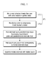
- FIG. 1 is a flow chart of a method for manufacturing a rechargeable battery according to an embodiment of the present invention
- FIG. 2 is a cross-sectional view of an embodiment of a plate for molding including an active material and a current collector
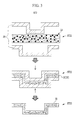
- FIG. 3 is a series of cross-sectional views illustrating an embodiment of a process for molding an electrode using an embodiment of the plate.
- a method for manufacturing a rechargeable battery includes manufacturing a plate 10 (ST1), manufacturing an electrode 30 (ST2), molding a pouch (ST3), and assembling an electrode assembly with the pouch (ST4).
- the plate 10 is manufactured by mixing an active material 11, the active material including active material particles (e.g., the active material being in a particle state), and a current collector 12 including a metal fiber yarn (ST11).
- the manufacturing of the plate ST1 can include mixing the active material particles and the metal fiber yarn (e.g., it can include embedding the active material particles in the current collector).
- the manufacturing of the plate ST1 further includes compressing the resultant mixed product (ST12).
- the plate 10 may be manufactured by being compressed and then undergoing a sintering process.
- the metal fiber yarn in the plate acts as a current collector for the active material particles.
- the active material 11 is bound with a strong fastening force by the current collector 12 (e.g., the active material 11 is supported by or embedded in the current collector 12).
- the current collector 12 includes (e.g., is formed of) the metal fiber yarn and, thus, the current collector 12 (or the metal fiber yarn) is formed to be longer than a maximum diameter of the active material 11, such that a current smoothly flows between particles of the active material 11.
- the plate 10 is an intermediate product of an embodiment of the process for manufacturing the electrode 30.
- the plate 10 is between electrode molds 20 having a predetermined (or set) shape (ST21), the plate 10 is pressed (ST22) (e.g., the pressing is performed), and then the pressed plate 10 is drawn out from the electrode molds 20 as the electrode 30 having a shape corresponding to that of the electrode molds 20 (ST23).
- the electrode 30 has a three-dimensional shape.
- FIG. 3 illustrates the electrode mold 20 having a bent shape, but the electrode mold 20 may have (e.g., be formed in) any suitable shape, such as various three-dimensional shapes having a concave and/or convex structure.
- the plate 10 includes (e.g., is formed of) the active material 11 in the particle state and the metal fiber yarn of the current collector 12 and, thus, the plate is molded (or deformed) to have a shape corresponding to the shape of the electrode mold 20, thereby molding the electrode 30.
- the active material 11 and the current collector 12 flow (e.g., flow together) when the plate 10 is molded (or deformed) into the electrode 30.
- the molded electrode 30 may keep a conducting structure (e.g., an electrically conductive structure) between the active material particles due to the presence of the current collector 12, and the electrode 30 may have high energy density.
- one or more positive electrodes and one or more negative electrodes can be formed from plates in the above described way, and that the electrode assembly of the battery can comprise these positive and negative electrodes in a stack along with a separator.
- the one or more positive electrodes may be formed using positive active material and metal fiber yarn as a current collector, and the one or more negatice electrodes may be formed using negative active material and metal fiber yarn as a current collector.
- the one or more positive electrodes and the one or more negative electrodes may be formed to have corresponding shapes.
- a pouch 40 is molded using a pouch mold corresponding to the three-dimensional shape of the electrode 30.
- a sheet is between the pouch molds, the sheet is pressed, and then the pressed sheet is drawn out, thereby obtaining the pouch 40 (shown in FIGS. 4-6 ) having a shape corresponding to that of the pouch mold.
- the pouch 40 has a three-dimensional shape.
- the pouch 40 is configured (or formed) to receive (i.e. to accommodate) an electrode assembly 50 (shown in FIG. 5 ) including the electrode 30, along with an electrolytic solution.
- the pouch mold has a shape corresponding to that of the molded electrode 30 and the electrode mold, and may have any suitable shape, such as various three-dimensional shapes having the concave and/or convex structure.
- the molded electrodes 30 are located on both surfaces of a separator 33, and the electrode assembly 50, which includes a lead tab 60 extending from the electrode 30, is assembled with the pouch 40 (shown in FIG. 5 ).
- the assembling of the electrode assembly ST4 includes inserting the electrode assembly 50 into the pouch 40, and heat-fusing and sealing an edge of the pouch 40. Further, in the assembling of the electrode assembly ST4, the electrolytic solution may be injected into the pouch 40 prior to sealing the pouch 40 and/or after sealing the pouch 40 by any suitable method generally used in the art.
- FIG. 4 is a perspective view of a rechargeable battery according to an embodiment of the present invention and FIG. 5 is an exploded perspective view of the rechargeable battery of FIG. 4 .
- the rechargeable battery 100 includes the electrode assembly 50 which is capable of charging and discharging, and the pouch 40 for receiving the electrode assembly 50.
- the electrode assembly 50 includes a separator 33, a pair of (e.g., two or more) electrodes 30 (for example, a negative electrode 31 and a positive electrode 32) respectively on two (e.g., both) surfaces of the separator 33, and a pair of (e.g., two or more) lead tabs 60 (for example, a negative electrode lead tab 61 and a positive electrode lead tab 62, which extend from the negative electrode 31 and the positive electrode 32, respectively).
- the negative electrode 31 and a positive electrode 32 may be formed from plates as discussed above.
- the electrode assembly 50 has (e.g., is formed in) a three-dimensional structure corresponding to the shape of the molded electrode 30 (e.g., the negative and positive electrodes 31 and 32) and draws out the negative and positive electrode lead tabs 61 and 62 to one side thereof.
- the separator 33 may include (e.g., be formed of) a polymer film through which a lithium ion may pass.
- the negative and positive electrodes 31 and 32 have a first bending part C1 formed by molding (or deforming) a plate 10, which is formed by mixing the active material 11 in the particle state (e.g., the active material particles) and the metal fiber yarn of the current collector 12 (or by embedding the active material particles in the current collector) and pressing the resultant mixed product.
- the negative and positive electrode lead tabs 61 and 62 are attached to one side of the negative and positive electrodes 31 and 32 and, thus, are electrically connected to the current collector 12.
- the negative and positive electrodes 31 and 32 are formed of a thicker film than are comparable electrodes formed of an aluminum or copper thin film according to the related art, thereby embodiments of the present disclosure implement the high-capacity and high-efficiency of the rechargeable battery 100.
- the first bending part C1 is a part that sets a difference in height between the negative and positive electrodes 31 and 32 based on a plane.
- a portion of the negative electrode 31 and/or the positive electrode 32 lies within a plane and an other portion of the negative electrode 31 and/or the positive electrode 32 lies outside of the plane.
- the first bending part C1 allows the negative and positive electrodes 31 and 32 to have any suitable shape, such as various three-dimensional shapes deviating from a plane state.
- the first bending part may include a plurality of (e.g., two or more) bends, in which the plurality of bends are connected to each other and, thus, may be formed concavely and/or convexly (e.g., may have a concave and/or convex shape) like a human face shape.
- the first bending part C1 of the negative and positive electrodes 31 and 32 includes a first bend C11 and a second bend C12.
- the first bending part C1 has a first bend C11 at two (e.g., both) sides of the first plane part 311 and 321 of the negative and positive electrodes 31 and 32.
- the first bend C11 has (e.g., is bent at) an angle (e.g., a right angle) with respect to the first plane parts 311 and 321 of the negative and positive electrodes 31 and 32.
- the first bending part C1 also has a second bend C12 having (e.g., bent at) an angle (e.g., a right angle) from side portions 313 and 323, which are connected to the first bend C11, to connect second plane parts 312 and 322, which are parallel (e.g., substantially parallel) with an extending direction of the first plane parts 311 and 321, to the side parts 313 and 323.
- a second bend C12 having (e.g., bent at) an angle (e.g., a right angle) from side portions 313 and 323, which are connected to the first bend C11, to connect second plane parts 312 and 322, which are parallel (e.g., substantially parallel) with an extending direction of the first plane parts 311 and 321, to the side parts 313 and 323.
- the negative and positive electrodes 31 and 32 are formed to have the first and second bends C11 and C12, the side portions 313 and 323 at two (e.g., both) sides of the first plane parts 311 and 321, and the second plane parts 312 and 322 connected to the side parts 313 and 323, respectively.
- the negative and positive electrodes 31 and 32 may be formed to have different shapes to those described above.
- the pouch 40 receives the electrode assembly 50 including the negative and positive electrodes 31 and 32 and is configured (or formed) to draw out the negative and positive electrode lead tabs 61 and 62 to one side. Further, the pouch 40 receives the electrode assembly 50 in the state in which the pouch 40 is superimposed with the electrode assembly 50 and the negative and positive electrodes 31 and 32 configuring the electrode assembly 50 in parallel (e.g., substantially in parallel) with each other. For example, the pouch 40 receives the electrode assembly 50 in such a way that the shape of the pouch 40 is superimposed with shape of the electrode assembly 50 and the negative and positive electrodes 31 and 32, and the shapes are parallel (e.g., substantially parallel) with one another.
- the pouch 40 is superimposed with the negative and positive electrodes 31 and 32 in parallel (e.g., substantially in parallel) with each other and has a second bending part C2 formed by molding (or deforming) the sheet used to form the pouch to have a shape corresponding to that of the first bending part C1. Therefore, the rechargeable battery 100 has a shape in which the first and second bending parts C1 and C2 are superimposed with each other, and have shapes corresponding to each other.
- the pouch 40 includes a concave member 41 and a plane member 42, which receive the electrode assembly 50.
- the concave member 41 has a concave part 411, which receives the electrode assembly 50 to surround (e.g., at least partially surround) an outside of the electrode assembly 50.
- the plane member 42 covers (e.g., at least partially covers) the electrode assembly 50 and is heat-fused to an edge 412 of the concave member 41 to form the sealed pouch 40.
- the pouch 40 has (e.g., is formed to have) a multilayered sheet structure and includes, for example, a polymer sheet 121, which forms an inner surface of the pouch 40 for insulating and heat fusion action, and a polyethyleneterephthalate (PET) sheet, a nylon sheet, or a PET-nylon composite sheet 122, which forms an outer surface for protection.
- a polymer sheet 121 which forms an inner surface of the pouch 40 for insulating and heat fusion action
- PET polyethyleneterephthalate
- nylon sheet e.g., polyethyleneterephthalate
- PET-nylon composite sheet 122 which forms an outer surface for protection.
- the pouch 40 further includes a metal sheet 123 which is between the polymer sheet 121 and the polyethyleneterephthalate (PET) sheet, nylon sheet, or PET-nylon composite sheet 122 to provide mechanical strength.
- the metal sheet 123 may include (e.g., be formed of) an aluminum sheet.
- the negative and positive electrode lead tabs 61 and 62 are drawn out (e.g., protrude) to the same side of the electrode assembly 50, but the present disclosure is not limited thereto.
- the negative and positive electrode lead tabs may be drawn out (e.g., protrude) to opposite sides of the electrode assembly.
- the electrode assembly 50 may be electrically connected to the outside of the pouch 40.
- insulating members 161 and 162 may coat the negative and positive electrode lead tabs 61 and 62, respectively, on the pouch 40 to electrically insulate the negative and positive electrode lead tabs 61 and 62 from the pouch 40 and to improve the insulation between the negative and positive electrode lead tabs 61 and 62.
- the second bending part C2 is a part that sets a height difference at the concave member 41 and the plane member 42 based on the plane so that the second bending part C2 is superimposed with the first bending part C1, and has a shape corresponding to that of the first bending part C1.
- a portion of the concave member 41 and the plane member 42 lies within a plane and an other portion of the concave member 41 and the plane member 42 lies outside of the plane.
- the second bending part C2 allows the concave member 41 and the plane member 42 to have any suitable shape, such as various three-dimensional shapes deviating from a planar shape.
- the second bending part may also be formed concavely and/or convexly like a human face shape, and have a shape corresponding to that of the first bending part.
- the second bending part C2 of the concave member 41 and the plane member 42 includes a third bend C21 and a fourth bend C22.
- the third bend C21 occurs (e.g., is bent) at the concave member 41 and the plane member 42 to have a shape corresponding to that of the first bend C11
- the fourth bend C22 occurs (e.g., is bent) at the concave member 41 and the plane member 42 to have a shape corresponding to that of the second bend C12.
- reference numerals for the second bending part C2, the third bend C21, and the fourth bend C22 are illustrated only at the concave member 41 and are not illustrated at the plane member 42.
- FIG. 6 is a cross-sectional view of the rechargeable battery of FIG. 4 taken along line VI-VI
- FIG. 7 is a cross-sectional view of a portion of the electrode assembly of FIG. 6
- the separator 33 may have adhesion (e.g., the separator may be adhesive or include an adhesive).
- the negative and positive electrodes 31 and 32 are respectively stacked and attached on two (e.g., both) surfaces of the separator 33 having adhesion.
- the negative electrode 31 may be adhered to a surface of the separator 33
- the positive electrode 32 may be adhered to an other surface of the separator 33.
- the negative and positive electrodes 31 and 32 and the separator 33 are stacked with each other.
- the adhesion of the separator 33 may fix the negative and positive electrodes 31 and 32 to the two (e.g., both) surfaces of the separator 33. Therefore, the stacking process of the negative and positive electrodes 31 and 32 and the separator 33 is readily performed.
- the negative and positive electrodes 31 and 32 may be formed with the same (e.g., substantially the same) thickness. Therefore, the negative and positive electrodes 31 and 32 may be manufactured by the same (e.g., substantially the same) process, thereby simplifying the manufacturing process. In this case, in the assembling of the electrode assembly ST4, the negative and positive electrodes 31 and 32 are formed with the same (e.g., substantially the same) thickness and may be stacked and attached on the two (e.g., both) surfaces of the separator 33.
- FIG. 8 is a cross-sectional view of a portion of an electrode assembly of another embodiment of the present invention.
- a positive electrode 72 includes (e.g., is formed of) one sheet and a negative electrode 71 includes (e.g., is formed of) two sheets.
- the electrode assembly 250 is formed by locating separators 73 on two (e.g., both) surfaces of a sheet of the positive electrode 72, respectively, and locating one of the negative electrodes 71 on each separator 73.
- the separators 73 are stacked on the two (e.g., both) surfaces of the positive electrode 72, respectively, and the negative electrodes 71 are attached to the separators 73, respectively.
- the negative and positive electrodes 71 and 72 are formed to be a thick film to implement (or provide) high capacity, but that may degrade performance due to the constraints of current and ion conductive characteristics as a thickness of the electrode is increased.
- the thin negative electrodes 71 are on the two (e.g., both) surfaces of the thick positive electrode 72, thereby overcoming the constraints of the current and ion conductive characteristics. Further, waste of the active material and the current collector resulting from having a portion of the active material and current collector in the negative electrode 71 that does not function (or does not provide a substantial function) due to an excessive thickness of the negative electrode 71 may be prevented (or mitigated).
- the electrode assembly 250 includes one positive electrode 72 and two negative electrodes 71, but the present disclosure is not limited thereto.
- the electrode assembly may include n positive electrodes 72 and n+1 stacked negative electrodes 71 and obtain the same (e.g., substantially the same) effect as the present embodiment of the present invention at the outermost.
- n may be any suitable integer.
- FIG. 9 is a cross-sectional view of a portion of an electrode assembly according to yet another embodiment of the present invention.
- an electrode assembly 350 is formed by alternately stacking the negative electrode 81 and the positive electrode 82, while having a separator 83 therebetween.
- n positive electrodes 82 are present and n + 1 negative electrodes 81 are present.
- n may be any suitable integer.
- the negative electrode 81 includes an outer negative electrode 811 and an inner negative electrode 812.
- a 1/2 portion e.g., T11/2, T2/2
- embodiments of the invention can provide a rechargeable battery, comprising: an electrode assembly comprising a pair of electrodes on respective surfaces of a separator, and a lead tab extending from each electrode; and a pouch accommodating the electrode assembly, wherein the lead tabs protrude from a side of the pouch, wherein each of the electrodes comprises a mixture of active material particles and metal fiber yarn (e.g. acting as a current collector), and the pouch having a shape corresponding to that of the electrodes.
- the pair of electrodes (which are formed to have corresponding shapes) can be formed in various different shapes, and the pouch is formed to have a shape corresponding to that of the electrodes.
- each of the electrodes comprises a first bending part comprising a molded plate and the pouch comprises a second bending part superimposed on the electrodes in parallel and comprising a molded sheet having a shape corresponding to that of the first bending part.
- Embodiments of the invention can also provide a method for manufacturing a rechargeable battery, the method comprising: manufacturing two plates, each plate being manufactured by mixing an active material comprising active material particles and a metal fiber yarn and compressing the resultant mixed product; molding two electrodes each having a set shape by respectively pressing the plates utilizing an electrode mold; molding a pouch utilizing a pouch mold having a shape corresponding to the set shape of the electrodes; and assembling an electrode assembly with the pouch by locating the electrodes on respective surfaces of a separator and extending a lead tab from each electrode.
Landscapes
- Chemical & Material Sciences (AREA)
- Chemical Kinetics & Catalysis (AREA)
- Electrochemistry (AREA)
- General Chemical & Material Sciences (AREA)
- Engineering & Computer Science (AREA)
- Manufacturing & Machinery (AREA)
- Secondary Cells (AREA)
- Battery Electrode And Active Subsutance (AREA)
Abstract
Description
- Aspects of embodiments according to the present disclosure relate generally to a rechargeable battery that may be manufactured and used in various three-dimensional shapes, and a manufacturing method of the same.
- A rechargeable battery is a battery that is configured to repeatedly perform charging and discharging, unlike a primary battery, which is not designed to be repeatedly charged and discharged. A small-capacity rechargeable battery is used in small portable electronic devices, such as a mobile phone, a tablet computer, a laptop computer, and a camcorder. A large-capacity rechargeable battery is used as a power supply for driving a motor, for an electric bicycle, a scooter, an electric vehicle, a fork lift, and the like.
- The above information disclosed in this Background section is only for enhancing the understanding of the background of the described technology and therefore it may contain information that does not form the prior art that is already known in this country to a person of ordinary skill in the art.
- Aspects of embodiments of the described technology are directed toward a rechargeable battery that may be manufactured and used in various three-dimensional shapes. Further, aspects of embodiments of the present invention are directed toward a method for manufacturing the rechargeable battery.
- An embodiment of a rechargeable battery includes: an electrode assembly including a pair of electrodes on respective surfaces of a separator, and a pair of lead tabs extending from the pair of electrodes; and a pouch receiving the electrode assembly and having the lead tabs protruding out to one side. Each of the electrodes includes a first bending part including a molded plate including a mixture of active material particles and a metal fiber yarn of a current collector. The pouch includes a second bending part superimposed on the electrode in parallel and includes a molded sheet having a shape corresponding to that of the first bending part.
- The separator may be adhesive. The pair of electrodes and the separator may be stacked together. A thickness of each of the pair of electrodes may be the same.
- The pouch may include: a concave member having a concave part receiving the electrode assembly to at least partially surround an outside of the electrode assembly; and a plane member at least partially covering the electrode assembly and heat-fused to an edge of the concave member.
- The first bending part may include: a first bend at a right angle at each of two sides of respective first plane parts of the pair of electrodes; and a second bend at a right angle at a side part connected to the first bend, the second bend being connected to second plane parts parallel to respective extending directions of the first plane parts.
- The second bending part may include: a third bend at the concave member and the plane member and having a shape corresponding to that of the first bend of the first bending part; and a fourth bend at the concave member and the plane member and having a shape corresponding to that of the second bend of the first bending part.
- The pair of electrodes may include a positive electrode and a negative electrode, the positive electrode may include one sheet, and the negative electrode may include two sheets, each of the sheets of the negative electrode being on a respective surface of the sheet of the positive electrode and having the separator therebetween.
- A thickness of each sheet of the negative electrode may be equal to 1/2 of a thickness of the sheet of the positive electrode.
- The electrode assembly may include alternately stacked n positive electrodes and n + 1 negative electrodes, n being an integer.
- The negative electrode may include: an outer negative electrode at an outermost side of the electrode assembly and having a thickness equal to 1/2 of a thickness of one of the n positive electrodes; and an inner negative electrode in the electrode assembly and having a thickness that is the same thickness as that of one of the n positive electrodes.
- Another embodiment provides a method for manufacturing a rechargeable battery including: manufacturing a plate by mixing active material particles and a metal fiber yarn of a current collector and compressing the resultant mixed product; molding an electrode having a set shape by pressing the plate utilizing an electrode mold; molding a pouch utilizing a pouch mold having a shape corresponding to the set shape of the electrode; and assembling an electrode with the pouch by locating the electrode on two surfaces of a separator and extending a lead tab from the electrode.
- The surfaces of the separator may be adhesive and the electrode may be stacked and attached on the surfaces of the separator.
- The electrode may include two or more electrodes, thicknesses of the electrodes may be the same and stacked and attached on the surfaces of the separator.
- The electrode may include a positive electrode including one sheet and a negative electrode including two sheets, the separator includes two separators, and in the assembling of the electrode assembly, the sheets of the negative electrode may be respectively attached to the separators by stacking the separators on respective surfaces of the positive electrode.
- The sheets of the negative electrode may each have a thickness that is 1/2 of a thickness of the sheet of the positive electrode.
- According to an aspect of the invention, there is provided a rechargeable battery as set out in claim 1. Preferred features are set out in claims 2 to 10.
- According to an aspect of the invention, there is provided a method for manufacturing a rechargeable battery as set out in
claim 11. Preferred features are set out inclaims 12 to 15. - As set forth above, according to aspects of embodiments of the disclosure, it is possible to manufacture the rechargeable battery in various three-dimensional shapes by forming the plate with the resultant mixed product of the active material particles and the metal fiber yarn of the current collector, forming the electrode by molding the plate, forming the pouch to have a shape corresponding to that of the electrode to assemble the electrode assembly and the pouch.
- For example, according to embodiments of the disclosure, it is possible to more efficiently use a rechargeable battery (e.g., more efficiently than a rechargeable battery having a shape according to the related art) by manufacturing the rechargeable battery in a shape corresponding to a space and shape which may be allowed (or accommodated) in various devices.
- The accompanying drawings, together with the specification, illustrate embodiments of the present disclosure, and, together with the description, serve to explain the principles of the present disclosure.
-
FIG. 1 is a flow chart illustrating a method for manufacturing a rechargeable battery according to an embodiment. -
FIG. 2 is a cross-sectional view of an embodiment of a plate for molding including an active material and a current collector. -
FIG. 3 is a series of cross-sectional views illustrating an embodiment of a process for molding an electrode using an embodiment of the plate. -
FIG. 4 is a perspective view of a rechargeable battery according to an embodiment. -
FIG. 5 is an exploded perspective view of the rechargeable battery ofFIG. 4 . -
FIG. 6 is a cross-sectional view of the rechargeable battery ofFIG. 4 taken along line VI-VI. -
FIG. 7 is a cross-sectional view of a portion of an electrode assembly of the rechargeable battery ofFIG. 6 . -
FIG. 8 is a cross-sectional view of a portion of an electrode assembly according to another embodiment. -
FIG. 9 is a cross-sectional view of a portion of an electrode assembly according to yet another embodiment. - Hereinafter, the present invention will be described more fully with reference to the accompanying drawings, in which certain embodiments of the invention are shown, by way of illustration. As those skilled in the art would realize, the described embodiments may be modified in many different ways, all without departing from the scope of the present invention. The drawings and description are to be regarded as illustrative in nature and not restrictive. Like reference numerals designate like elements throughout the specification. Also, in the context of the present application, when a first element is referred to as being "on" a second element, it can be directly on the second element or be indirectly on the second element with one or more intervening elements therebetween.
- Generally, a rechargeable battery is formed in a circular shape or a quadrangular shape (e.g., a square shape) in which an electrode assembly is received in a metal case, or a pouchshape. Because the rechargeable battery has the circular shape, the quadrangular shape, or the pouch shape, the rechargeable battery is limited in its ability to appropriately correspond to a shape of the device in which the battery is used. Hereinafter, embodiments according to the present disclosure will be described, which relate to a rechargeable battery that may be manufactured in a shape corresponding to a space and shape which may be allowed (or accommodated) in various devices, and a method for manufacturing the same.
-
FIG. 1 is a flow chart of a method for manufacturing a rechargeable battery according to an embodiment of the present invention,FIG. 2 is a cross-sectional view of an embodiment of a plate for molding including an active material and a current collector, andFIG. 3 is a series of cross-sectional views illustrating an embodiment of a process for molding an electrode using an embodiment of the plate. - Referring to
FIGS. 1 to 3 , a method for manufacturing a rechargeable battery according to an embodiment of the present invention includes manufacturing a plate 10 (ST1), manufacturing an electrode 30 (ST2), molding a pouch (ST3), and assembling an electrode assembly with the pouch (ST4). - In the manufacturing of the plate ST1, the
plate 10 is manufactured by mixing anactive material 11, the active material including active material particles (e.g., the active material being in a particle state), and acurrent collector 12 including a metal fiber yarn (ST11). For example, the manufacturing of the plate ST1 can include mixing the active material particles and the metal fiber yarn (e.g., it can include embedding the active material particles in the current collector). Then, the manufacturing of the plate ST1 further includes compressing the resultant mixed product (ST12). In the manufacturing of the plate (ST1), theplate 10 may be manufactured by being compressed and then undergoing a sintering process. In other words, the metal fiber yarn in the plate acts as a current collector for the active material particles. - In the
plate 10, theactive material 11 is bound with a strong fastening force by the current collector 12 (e.g., theactive material 11 is supported by or embedded in the current collector 12). Thecurrent collector 12 includes (e.g., is formed of) the metal fiber yarn and, thus, the current collector 12 (or the metal fiber yarn) is formed to be longer than a maximum diameter of theactive material 11, such that a current smoothly flows between particles of theactive material 11. Theplate 10 is an intermediate product of an embodiment of the process for manufacturing theelectrode 30. - In the manufacturing of the
electrode 30 ST2, theplate 10 is betweenelectrode molds 20 having a predetermined (or set) shape (ST21), theplate 10 is pressed (ST22) (e.g., the pressing is performed), and then the pressedplate 10 is drawn out from theelectrode molds 20 as theelectrode 30 having a shape corresponding to that of the electrode molds 20 (ST23). For example, theelectrode 30 has a three-dimensional shape. - For convenience, according to the present embodiment of the present invention,
FIG. 3 illustrates theelectrode mold 20 having a bent shape, but theelectrode mold 20 may have (e.g., be formed in) any suitable shape, such as various three-dimensional shapes having a concave and/or convex structure. - The
plate 10 includes (e.g., is formed of) theactive material 11 in the particle state and the metal fiber yarn of thecurrent collector 12 and, thus, the plate is molded (or deformed) to have a shape corresponding to the shape of theelectrode mold 20, thereby molding theelectrode 30. Theactive material 11 and thecurrent collector 12 flow (e.g., flow together) when theplate 10 is molded (or deformed) into theelectrode 30. Nevertheless, because the current collector 12 (or the metal fiber yarn) has a length still longer than the diameter of theactive material 11, the moldedelectrode 30 may keep a conducting structure (e.g., an electrically conductive structure) between the active material particles due to the presence of thecurrent collector 12, and theelectrode 30 may have high energy density. - It will be appreciated that one or more positive electrodes and one or more negative electrodes can be formed from plates in the above described way, and that the electrode assembly of the battery can comprise these positive and negative electrodes in a stack along with a separator.
- The one or more positive electrodes may be formed using positive active material and metal fiber yarn as a current collector, and the one or more negatice electrodes may be formed using negative active material and metal fiber yarn as a current collector.
- The one or more positive electrodes and the one or more negative electrodes may be formed to have corresponding shapes.
- In the molding of the pouch ST3, a
pouch 40 is molded using a pouch mold corresponding to the three-dimensional shape of theelectrode 30. As in the molding of theelectrode 30, in the molding of the pouch ST3, a sheet is between the pouch molds, the sheet is pressed, and then the pressed sheet is drawn out, thereby obtaining the pouch 40 (shown inFIGS. 4-6 ) having a shape corresponding to that of the pouch mold. For example, thepouch 40 has a three-dimensional shape. - The
pouch 40 is configured (or formed) to receive (i.e. to accommodate) an electrode assembly 50 (shown inFIG. 5 ) including theelectrode 30, along with an electrolytic solution. Further, the pouch mold has a shape corresponding to that of the moldedelectrode 30 and the electrode mold, and may have any suitable shape, such as various three-dimensional shapes having the concave and/or convex structure. - In the assembling of the electrode assembly ST4, the molded
electrodes 30 are located on both surfaces of aseparator 33, and theelectrode assembly 50, which includes alead tab 60 extending from theelectrode 30, is assembled with the pouch 40 (shown inFIG. 5 ). - The assembling of the electrode assembly ST4 includes inserting the
electrode assembly 50 into thepouch 40, and heat-fusing and sealing an edge of thepouch 40. Further, in the assembling of the electrode assembly ST4, the electrolytic solution may be injected into thepouch 40 prior to sealing thepouch 40 and/or after sealing thepouch 40 by any suitable method generally used in the art. - Hereinafter, a configuration of the
electrode 30, thepouch 40, and theelectrode assembly 50 will be described in more detail, while describing a configuration of therechargeable battery 100. -
FIG. 4 is a perspective view of a rechargeable battery according to an embodiment of the present invention andFIG. 5 is an exploded perspective view of the rechargeable battery ofFIG. 4 . Referring toFIGS. 4 and5 , therechargeable battery 100 includes theelectrode assembly 50 which is capable of charging and discharging, and thepouch 40 for receiving theelectrode assembly 50. - The
electrode assembly 50 includes aseparator 33, a pair of (e.g., two or more) electrodes 30 (for example, anegative electrode 31 and a positive electrode 32) respectively on two (e.g., both) surfaces of theseparator 33, and a pair of (e.g., two or more) lead tabs 60 (for example, a negativeelectrode lead tab 61 and a positiveelectrode lead tab 62, which extend from thenegative electrode 31 and thepositive electrode 32, respectively). As discussed, thenegative electrode 31 and apositive electrode 32 may be formed from plates as discussed above. - For example, the
electrode assembly 50 has (e.g., is formed in) a three-dimensional structure corresponding to the shape of the molded electrode 30 (e.g., the negative andpositive electrodes 31 and 32) and draws out the negative and positiveelectrode lead tabs separator 33 may include (e.g., be formed of) a polymer film through which a lithium ion may pass. - In this embodiment, the negative and
positive electrodes plate 10, which is formed by mixing theactive material 11 in the particle state (e.g., the active material particles) and the metal fiber yarn of the current collector 12 (or by embedding the active material particles in the current collector) and pressing the resultant mixed product. The negative and positiveelectrode lead tabs positive electrodes current collector 12. - As described above, the negative and
positive electrodes rechargeable battery 100. - In this embodiment, the first bending part C1 is a part that sets a difference in height between the negative and
positive electrodes negative electrode 31 and/or thepositive electrode 32 lies within a plane and an other portion of thenegative electrode 31 and/or thepositive electrode 32 lies outside of the plane. For example, the first bending part C1 allows the negative andpositive electrodes - For example, the first bending part C1 of the negative and
positive electrodes first plane part positive electrodes first plane parts positive electrodes side portions second plane parts first plane parts side parts - For example, the negative and
positive electrodes side portions first plane parts second plane parts side parts - In other embodiments, the negative and
positive electrodes - The
pouch 40 receives theelectrode assembly 50 including the negative andpositive electrodes electrode lead tabs pouch 40 receives theelectrode assembly 50 in the state in which thepouch 40 is superimposed with theelectrode assembly 50 and the negative andpositive electrodes electrode assembly 50 in parallel (e.g., substantially in parallel) with each other. For example, thepouch 40 receives theelectrode assembly 50 in such a way that the shape of thepouch 40 is superimposed with shape of theelectrode assembly 50 and the negative andpositive electrodes - For example, the
pouch 40 is superimposed with the negative andpositive electrodes rechargeable battery 100 has a shape in which the first and second bending parts C1 and C2 are superimposed with each other, and have shapes corresponding to each other. - For example, the
pouch 40 includes aconcave member 41 and aplane member 42, which receive theelectrode assembly 50. Theconcave member 41 has aconcave part 411, which receives theelectrode assembly 50 to surround (e.g., at least partially surround) an outside of theelectrode assembly 50. Theplane member 42 covers (e.g., at least partially covers) theelectrode assembly 50 and is heat-fused to anedge 412 of theconcave member 41 to form the sealedpouch 40. - The
pouch 40 has (e.g., is formed to have) a multilayered sheet structure and includes, for example, a polymer sheet 121, which forms an inner surface of thepouch 40 for insulating and heat fusion action, and a polyethyleneterephthalate (PET) sheet, a nylon sheet, or a PET-nylon composite sheet 122, which forms an outer surface for protection. - For example, the
pouch 40 further includes a metal sheet 123 which is between the polymer sheet 121 and the polyethyleneterephthalate (PET) sheet, nylon sheet, or PET-nylon composite sheet 122 to provide mechanical strength. For example, the metal sheet 123 may include (e.g., be formed of) an aluminum sheet. - The negative and positive
electrode lead tabs electrode assembly 50, but the present disclosure is not limited thereto. For example, the negative and positive electrode lead tabs may be drawn out (e.g., protrude) to opposite sides of the electrode assembly. - Because the negative and positive
electrode lead tabs pouch 40, theelectrode assembly 50 may be electrically connected to the outside of thepouch 40. In this case, insulatingmembers electrode lead tabs pouch 40 to electrically insulate the negative and positiveelectrode lead tabs pouch 40 and to improve the insulation between the negative and positiveelectrode lead tabs - The second bending part C2 is a part that sets a height difference at the
concave member 41 and theplane member 42 based on the plane so that the second bending part C2 is superimposed with the first bending part C1, and has a shape corresponding to that of the first bending part C1. As a result of the presence of the second bending part C2, a portion of theconcave member 41 and theplane member 42 lies within a plane and an other portion of theconcave member 41 and theplane member 42 lies outside of the plane. For example, the second bending part C2 allows theconcave member 41 and theplane member 42 to have any suitable shape, such as various three-dimensional shapes deviating from a planar shape. The second bending part may also be formed concavely and/or convexly like a human face shape, and have a shape corresponding to that of the first bending part. - For example, the second bending part C2 of the
concave member 41 and theplane member 42 includes a third bend C21 and a fourth bend C22. The third bend C21 occurs (e.g., is bent) at theconcave member 41 and theplane member 42 to have a shape corresponding to that of the first bend C11, and the fourth bend C22 occurs (e.g., is bent) at theconcave member 41 and theplane member 42 to have a shape corresponding to that of the second bend C12. For convenience, inFIG. 5 , reference numerals for the second bending part C2, the third bend C21, and the fourth bend C22 are illustrated only at theconcave member 41 and are not illustrated at theplane member 42. -
FIG. 6 is a cross-sectional view of the rechargeable battery ofFIG. 4 taken along line VI-VI, andFIG. 7 is a cross-sectional view of a portion of the electrode assembly ofFIG. 6 . Referring toFIGS. 6 and7 , in theelectrode assembly 50, theseparator 33 may have adhesion (e.g., the separator may be adhesive or include an adhesive). In this case, according to the method for manufacturing a rechargeable battery, in the assembling of the electrode assembly ST4, the negative andpositive electrodes separator 33 having adhesion. For example, thenegative electrode 31 may be adhered to a surface of theseparator 33, and thepositive electrode 32 may be adhered to an other surface of theseparator 33. - The negative and
positive electrodes separator 33 are stacked with each other. In this case, the adhesion of theseparator 33 may fix the negative andpositive electrodes separator 33. Therefore, the stacking process of the negative andpositive electrodes separator 33 is readily performed. - The negative and
positive electrodes positive electrodes positive electrodes separator 33. - Hereinafter, another embodiment of the present invention will be described. Components of the present embodiment that are the same (e.g., substantially the same) as those described above will not be described further here, and different components will be described instead.
-
FIG. 8 is a cross-sectional view of a portion of an electrode assembly of another embodiment of the present invention. Referring toFIG. 8 , in anelectrode assembly 250, apositive electrode 72 includes (e.g., is formed of) one sheet and anegative electrode 71 includes (e.g., is formed of) two sheets. - For example, the
electrode assembly 250 is formed by locatingseparators 73 on two (e.g., both) surfaces of a sheet of thepositive electrode 72, respectively, and locating one of thenegative electrodes 71 on eachseparator 73. In this case, according to the present embodiment of the method for manufacturing a rechargeable battery, in the assembling of the electrode assembly ST4, theseparators 73 are stacked on the two (e.g., both) surfaces of thepositive electrode 72, respectively, and thenegative electrodes 71 are attached to theseparators 73, respectively. - For example, a thickness T1 of the
negative electrode 71 is formed to be 1/2 a thickness T2 of the positive electrode 72 (e.g., T1 = T2/2). In this case, in the assembling of the electrode assembly ST4, the thickness T1 of thenegative electrode 71 is formed to be 1/2 the thickness T2 of the positive electrode 72 (e.g., T1 = T2/2) and thenegative electrode 71 is attached to theseparator 73. - The negative and
positive electrodes negative electrodes 71 are on the two (e.g., both) surfaces of the thickpositive electrode 72, thereby overcoming the constraints of the current and ion conductive characteristics. Further, waste of the active material and the current collector resulting from having a portion of the active material and current collector in thenegative electrode 71 that does not function (or does not provide a substantial function) due to an excessive thickness of thenegative electrode 71 may be prevented (or mitigated). - The
electrode assembly 250 according to the present embodiment of the present invention includes onepositive electrode 72 and twonegative electrodes 71, but the present disclosure is not limited thereto. For example, the electrode assembly may include npositive electrodes 72 and n+1 stackednegative electrodes 71 and obtain the same (e.g., substantially the same) effect as the present embodiment of the present invention at the outermost. According to embodiments of the present disclosure, n may be any suitable integer. -
FIG. 9 is a cross-sectional view of a portion of an electrode assembly according to yet another embodiment of the present invention. Referring toFIG. 9 , anelectrode assembly 350 is formed by alternately stacking thenegative electrode 81 and thepositive electrode 82, while having aseparator 83 therebetween. - For example, n
positive electrodes 82 are present and n + 1negative electrodes 81 are present. According to embodiments of the present disclosure, n may be any suitable integer. In this case, thenegative electrode 81 includes an outernegative electrode 811 and an innernegative electrode 812. The outernegative electrode 811 is at two (e.g., both) outermost sides of theelectrode assembly 350 and has (e.g., is formed with) a thickness T1 that is 1/2 a thickness T2 of the positive electrode 82 (e.g., T1 = T2/2). The innernegative electrode 812 is in the electrode assembly 350 (e.g., at an interior of the electrode assembly 350) and has (e.g., is formed with) a thickness T11 that is the same (e.g., substantially the same) as the thickness T2 of the positive electrode 82 (e.g., T11 = T2). - The inner
negative electrode 812 and thepositive electrode 82, which are stacked in theelectrode assembly 350 and face each other, are each (e.g., are formed with) a thick film having the same (e.g., substantially the same) thickness (T11 = T2), but the electric current and ions are conducted at a 1/2 portion (e.g., T11/2, T2/2) at two (e.g., both) sides having the thicknesses T11 and T2 to overcome the constraints of the current and ion conductive characteristics. - Further, the outer
negative electrodes 811, which are stacked at the outermost sides of theelectrode assembly 350 and face each other, have (e.g., are formed with) the thickness T1 that is 1/2 the thickness of the positive electrode 82 (e.g., T1 = T2/2), such that the outernegative electrode 811 and thepositive electrode 82 may overcome the constraints of the current and ion conductive characteristics therebetween. Further, waste of the active material and the current collector resulting from having a portion of the active material and current collector in the outernegative electrode 811 that does not function (or does not provide a substantial function) due to an excessive thickness of the outernegative electrode 811 may be prevented (or mitigated). - As discussed, embodiments of the invention can provide a rechargeable battery, comprising: an electrode assembly comprising a pair of electrodes on respective surfaces of a separator, and a lead tab extending from each electrode; and a pouch accommodating the electrode assembly, wherein the lead tabs protrude from a side of the pouch, wherein each of the electrodes comprises a mixture of active material particles and metal fiber yarn (e.g. acting as a current collector), and the pouch having a shape corresponding to that of the electrodes.
- In such embodiments, the pair of electrodes (which are formed to have corresponding shapes) can be formed in various different shapes, and the pouch is formed to have a shape corresponding to that of the electrodes.
- In some embodiments, each of the electrodes comprises a first bending part comprising a molded plate and the pouch comprises a second bending part superimposed on the electrodes in parallel and comprising a molded sheet having a shape corresponding to that of the first bending part.
- Embodiments of the invention can also provide a method for manufacturing a rechargeable battery, the method comprising: manufacturing two plates, each plate being manufactured by mixing an active material comprising active material particles and a metal fiber yarn and compressing the resultant mixed product; molding two electrodes each having a set shape by respectively pressing the plates utilizing an electrode mold; molding a pouch utilizing a pouch mold having a shape corresponding to the set shape of the electrodes; and assembling an electrode assembly with the pouch by locating the electrodes on respective surfaces of a separator and extending a lead tab from each electrode.
- While this invention has been described in connection with what is presently considered to be practical embodiments, it is to be understood that the invention is not limited to the disclosed embodiments, but, on the contrary, is intended to cover various modifications and equivalent arrangements included within the scope of the appended claims, and equivalents thereof.
Claims (15)
- A rechargeable battery, comprising
an electrode assembly comprising a pair of electrodes on respective surfaces of a separator, and a lead tab extending from each electrode; and
a pouch accommodating the electrode assembly, wherein the lead tabs protrude from a side of the pouch,
wherein each of the electrodes comprises a mixture of active material particles and metal fiber yarn, and
the pouch having a shape corresponding to that of the electrodes. - The rechargeable battery of claim 1, wherein the separator is adhesive, and wherein the pair of electrodes and the separator are stacked together.
- The rechargeable battery of claim 2, wherein a thickness of each of the pair of electrodes is the same.
- The rechargeable battery of any one of claims 1 to 3, wherein each of the electrodes comprises a first bending part comprising a molded plate and the pouch comprises a second bending part superimposed on the electrodes in parallel and comprising a molded sheet having a shape corresponding to that of the first bending part.
- The rechargeable battery of claim 4, wherein the pouch comprises:a concave member having a concave part receiving the electrode assembly so as to at least partially surround an outside of the electrode assembly; anda plane member at least partially covering the electrode assembly and heat-fused to an edge of the concave member.
- The rechargeable battery of claim 5, wherein the first bending part comprises:a first bend at a right angle at each of two sides of respective first plane parts of the pair of electrodes; anda second bend at a right angle at a side part connected to the first bend, the second bend being connected to second plane parts parallel to respective extending directions of the first plane parts.
- The rechargeable battery of claim 6, wherein the second bending part comprises:a third bend at the concave member and the plane member and having a shape corresponding to that of the first bend of the first bending part; anda fourth bend at the concave member and the plane member and having a shape corresponding to that of the second bend of the first bending part.
- The rechargeable battery of any one of claims 1 to 7, wherein:the pair of electrodes comprises a positive electrode and a negative electrode,the positive electrode comprises one sheet, andthe negative electrode comprises two sheets, each of the sheets of the negative electrode being on a respective surface of the sheet of the positive electrode and having the separator therebetween;optionally wherein a thickness of each sheet of the negative electrode is equal to 1/2 of a thickness of the sheet of the positive electrode.
- The rechargeable battery of any one of claims 1 to 7, wherein the electrode assembly comprises alternately stacked n positive electrodes and n + 1 negative electrodes, n being an integer.
- The rechargeable battery of claim 9, wherein the negative electrode comprises:an outer negative electrode at an outermost side of the electrode assembly and having a thickness equal to 1/2 of a thickness of one of the n positive electrodes; andan inner negative electrode in the electrode assembly and having a thickness that is the same as that of the one of the n positive electrodes.
- A method for manufacturing a rechargeable battery, the method comprising:manufacturing two plates, each plate being manufactured by mixing an active material comprising active material particles and a metal fiber yarn and compressing the resultant mixed product;molding two electrodes each having a set shape by respectively pressing a said plate utilizing an electrode mold;molding a pouch utilizing a pouch mold having a shape corresponding to the set shape of the electrodes; andassembling an electrode assembly with the pouch by locating the electrodes on respective surfaces of a separator and extending a lead tab from each electrode.
- The method of claim 11, wherein the surfaces of the separator are adhesive and the electrodes are stacked and attached on the surfaces of the separator.
- The method of claim 12, wherein thicknesses of the two electrodes are the same, and the electrodes are stacked and attached on the surfaces of the separator.
- The method of claim 11 or 12, wherein:the electrodes comprise a positive electrode comprising one molded sheet and a negative electrode comprising two molded sheets,the separator comprises two separator sheets, andin the assembling of the electrode assembly, the sheets of the negative electrode are respectively attached to the separator sheets and the separator sheets are stacked on respective surfaces of the positive electrode.
- The method of claim 14, wherein the sheets of the negative electrode each have a thickness that is 1/2 of a thickness of the sheet of the positive electrode.
Applications Claiming Priority (1)
| Application Number | Priority Date | Filing Date | Title |
|---|---|---|---|
| KR1020130153222A KR101784739B1 (en) | 2013-12-10 | 2013-12-10 | Rechargeable battery and manufacturing method of the same |
Publications (1)
| Publication Number | Publication Date |
|---|---|
| EP2884559A1 true EP2884559A1 (en) | 2015-06-17 |
Family
ID=52146078
Family Applications (1)
| Application Number | Title | Priority Date | Filing Date |
|---|---|---|---|
| EP14197013.7A Ceased EP2884559A1 (en) | 2013-12-10 | 2014-12-09 | Rechargeable battery and manufacturing method of the same |
Country Status (4)
| Country | Link |
|---|---|
| US (1) | US9905816B2 (en) |
| EP (1) | EP2884559A1 (en) |
| KR (1) | KR101784739B1 (en) |
| CN (2) | CN104701567A (en) |
Families Citing this family (13)
| Publication number | Priority date | Publication date | Assignee | Title |
|---|---|---|---|---|
| KR20240055130A (en) * | 2012-08-16 | 2024-04-26 | 에노빅스 코오퍼레이션 | Electrode structures for three-dimensional batteries |
| CN105308772B (en) | 2013-03-15 | 2018-11-16 | 艾诺维克斯公司 | Separator for three-dimensional battery |
| TWI793480B (en) | 2015-05-14 | 2023-02-21 | 美商易諾維公司 | Longitudinal constraints for energy storage devices |
| KR101927262B1 (en) * | 2015-11-03 | 2018-12-10 | 주식회사 엘지화학 | A pouch case for a secondary battery |
| TWI739830B (en) | 2016-05-13 | 2021-09-21 | 美商易諾維公司 | Dimensional constraints for three-dimensional batteries |
| TWI819481B (en) | 2016-11-16 | 2023-10-21 | 美商易諾維公司 | Three-dimensional batteries with compressible cathodes |
| KR102859540B1 (en) | 2017-11-15 | 2025-09-17 | 에노빅스 코오퍼레이션 | Electrode assembly and secondary battery |
| US10256507B1 (en) | 2017-11-15 | 2019-04-09 | Enovix Corporation | Constrained electrode assembly |
| US11211639B2 (en) | 2018-08-06 | 2021-12-28 | Enovix Corporation | Electrode assembly manufacture and device |
| KR102158737B1 (en) * | 2019-02-14 | 2020-09-22 | 주식회사 유앤에스에너지 | Current collector for electrodes |
| KR102578784B1 (en) | 2019-12-17 | 2023-09-15 | 주식회사 엘지에너지솔루션 | Case for secondary battery and secondary battery |
| JP7844451B2 (en) | 2020-09-18 | 2026-04-13 | エノビクス・コーポレイション | Manufacturing of electrodes used in batteries |
| CN116783744A (en) | 2020-12-09 | 2023-09-19 | 艾诺维克斯公司 | Method and device for manufacturing electrode assembly of secondary battery |
Citations (8)
| Publication number | Priority date | Publication date | Assignee | Title |
|---|---|---|---|---|
| US6040078A (en) * | 1997-03-06 | 2000-03-21 | Mitsubishi Chemical Corporation | Free form battery apparatus |
| EP0991132A2 (en) * | 1998-09-17 | 2000-04-05 | Kabushiki Kaisha Toshiba | Nonaqueous electrolyte secondary battery and method of manufacturing nonaqueous electrolyte secondary battery |
| EP1104941A1 (en) * | 1998-07-27 | 2001-06-06 | Kanebo Limited | Organic electrolytic cell |
| WO2007118281A1 (en) * | 2006-04-18 | 2007-10-25 | Commonwealth Scientific And Industrial Research Organisation | Flexible energy storage devices |
| EP2251921A2 (en) * | 2008-03-12 | 2010-11-17 | LG Chem, Ltd. | Curved battery cell, and a battery pack comprising the same |
| US20120015236A1 (en) * | 2010-07-16 | 2012-01-19 | Apple Inc. | Design and construction of non-rectangular batteries |
| WO2012138115A2 (en) * | 2011-04-06 | 2012-10-11 | 주식회사 샤인 | Battery having electrode structure including metal fiber and preparation method of electrode structure |
| US20130280580A1 (en) * | 2012-04-10 | 2013-10-24 | Research Foundation Of The City University Of New York | Method for providing a stretchable power source and device |
Family Cites Families (7)
| Publication number | Priority date | Publication date | Assignee | Title |
|---|---|---|---|---|
| JP3591523B2 (en) * | 2002-04-11 | 2004-11-24 | 日産自動車株式会社 | Battery pack |
| JP2007273249A (en) | 2006-03-31 | 2007-10-18 | Arisawa Mfg Co Ltd | Method for producing lithium ion secondary battery |
| JP4380728B2 (en) * | 2007-05-16 | 2009-12-09 | ソニー株式会社 | Laminated packaging material, battery exterior member and battery |
| KR101199125B1 (en) * | 2010-09-02 | 2012-11-09 | 삼성에스디아이 주식회사 | Electrode assembly including bending portions and secondary battery having the same |
| KR101088073B1 (en) * | 2010-10-16 | 2011-12-01 | 주식회사 샤인 | Battery having an electrode structure including metal long fibers and method for manufacturing same |
| CN102166057B (en) * | 2011-01-30 | 2013-11-06 | 鲍翠玲 | Bracelet structure for communication or tracking |
| KR101161136B1 (en) | 2011-05-17 | 2012-06-29 | 주식회사 엘지화학 | Battery Cell of Curved Shape and Battery Pack Employed with the Same |
-
2013
- 2013-12-10 KR KR1020130153222A patent/KR101784739B1/en active Active
-
2014
- 2014-11-10 US US14/537,797 patent/US9905816B2/en active Active
- 2014-12-09 CN CN201410749067.5A patent/CN104701567A/en active Pending
- 2014-12-09 CN CN202110717691.7A patent/CN113571755B/en active Active
- 2014-12-09 EP EP14197013.7A patent/EP2884559A1/en not_active Ceased
Patent Citations (9)
| Publication number | Priority date | Publication date | Assignee | Title |
|---|---|---|---|---|
| US6040078A (en) * | 1997-03-06 | 2000-03-21 | Mitsubishi Chemical Corporation | Free form battery apparatus |
| EP1104941A1 (en) * | 1998-07-27 | 2001-06-06 | Kanebo Limited | Organic electrolytic cell |
| EP0991132A2 (en) * | 1998-09-17 | 2000-04-05 | Kabushiki Kaisha Toshiba | Nonaqueous electrolyte secondary battery and method of manufacturing nonaqueous electrolyte secondary battery |
| WO2007118281A1 (en) * | 2006-04-18 | 2007-10-25 | Commonwealth Scientific And Industrial Research Organisation | Flexible energy storage devices |
| EP2251921A2 (en) * | 2008-03-12 | 2010-11-17 | LG Chem, Ltd. | Curved battery cell, and a battery pack comprising the same |
| US20120015236A1 (en) * | 2010-07-16 | 2012-01-19 | Apple Inc. | Design and construction of non-rectangular batteries |
| WO2012138115A2 (en) * | 2011-04-06 | 2012-10-11 | 주식회사 샤인 | Battery having electrode structure including metal fiber and preparation method of electrode structure |
| EP2696399A2 (en) * | 2011-04-06 | 2014-02-12 | Shine Co., Ltd | Battery having electrode structure including metal fiber and preparation method of electrode structure |
| US20130280580A1 (en) * | 2012-04-10 | 2013-10-24 | Research Foundation Of The City University Of New York | Method for providing a stretchable power source and device |
Non-Patent Citations (2)
| Title |
|---|
| ANONYMOUS: "Pouch Cell Case/Cup Forming Machine for Aluminum-Laminated Film - MSK-120", 20 August 2013 (2013-08-20), XP055345415, Retrieved from the Internet <URL:http://web.archive.org/web/20130820092458/http://www.mtixtl.com/PouchCellCase/CupFormingMachine-MSK-120.aspx> [retrieved on 20170214] * |
| NANSI XUE ET AL: "Optimization of a Single Lithium-Ion Battery Cell with a Gradient-Based Algorithm", JOURNAL OF THE ELECTROCHEMICAL SOCIETY, 7 May 2013 (2013-05-07), pages 1071 - 1078, XP055179817, Retrieved from the Internet <URL:http://jes.ecsdl.org/content/160/8/A1071.full.pdf> [retrieved on 20150327], DOI: 10.1149/2.036308jes] * |
Also Published As
| Publication number | Publication date |
|---|---|
| US20150162575A1 (en) | 2015-06-11 |
| CN113571755B (en) | 2024-12-06 |
| US9905816B2 (en) | 2018-02-27 |
| CN113571755A (en) | 2021-10-29 |
| KR20150067591A (en) | 2015-06-18 |
| CN104701567A (en) | 2015-06-10 |
| KR101784739B1 (en) | 2017-10-12 |
Similar Documents
| Publication | Publication Date | Title |
|---|---|---|
| US9905816B2 (en) | Rechargeable battery and manufacturing method of the same | |
| EP2500972B1 (en) | Lithium secondary battery having multi-directional lead-tab structure | |
| JP6563589B2 (en) | Secondary battery pouch exterior | |
| US9660296B2 (en) | Electrode assembly having step, battery cell, battery pack and device including the same | |
| KR102382525B1 (en) | Secondary battery and secondary battery array | |
| CN209515763U (en) | Battery unit and battery module including the same | |
| EP2337106A2 (en) | Rechargeable battery | |
| CN114759246B (en) | Rechargeable battery | |
| CN105428691B (en) | Electrode assembly and secondary battery including the same | |
| EP2328199A2 (en) | Rechargeable battery | |
| JP7134543B2 (en) | Electrode assembly including plastic member applied to electrode tab lead connection and secondary battery including the same | |
| CN101640282B (en) | Stacked secondary battery | |
| CN102931374A (en) | Rechargeable battery and method for fabricating the same | |
| CN106486701B (en) | Electrode assembly, method for manufacturing the same, and rechargeable battery | |
| EP2323202A1 (en) | Electrode assembly | |
| CN105702999A (en) | Manufacturing method for secondary battery and secondary battery | |
| CN105938881A (en) | Rechargeable battery with cover | |
| KR20140110136A (en) | Battery Cell Having Lead-Tap Joint of Improved Coupling Force | |
| US20140255757A1 (en) | Rechargeable battery | |
| CN109716574B (en) | Rechargeable battery | |
| CN104347844A (en) | Electrode assembly, and rechargeable battery | |
| US9515343B2 (en) | Rechargeable battery | |
| CN109923724B (en) | rechargeable battery | |
| JP2017199651A (en) | Energy storage element | |
| JP7146386B2 (en) | Method for manufacturing electric storage element |
Legal Events
| Date | Code | Title | Description |
|---|---|---|---|
| PUAI | Public reference made under article 153(3) epc to a published international application that has entered the european phase |
Free format text: ORIGINAL CODE: 0009012 |
|
| 17P | Request for examination filed |
Effective date: 20141209 |
|
| AK | Designated contracting states |
Kind code of ref document: A1 Designated state(s): AL AT BE BG CH CY CZ DE DK EE ES FI FR GB GR HR HU IE IS IT LI LT LU LV MC MK MT NL NO PL PT RO RS SE SI SK SM TR |
|
| AX | Request for extension of the european patent |
Extension state: BA ME |
|
| R17P | Request for examination filed (corrected) |
Effective date: 20151217 |
|
| RBV | Designated contracting states (corrected) |
Designated state(s): AL AT BE BG CH CY CZ DE DK EE ES FI FR GB GR HR HU IE IS IT LI LT LU LV MC MK MT NL NO PL PT RO RS SE SI SK SM TR |
|
| STAA | Information on the status of an ep patent application or granted ep patent |
Free format text: STATUS: EXAMINATION IS IN PROGRESS |
|
| 17Q | First examination report despatched |
Effective date: 20170223 |
|
| STAA | Information on the status of an ep patent application or granted ep patent |
Free format text: STATUS: THE APPLICATION HAS BEEN REFUSED |
|
| 18R | Application refused |
Effective date: 20200416 |