EP2696399A2 - Battery having electrode structure including metal fiber and preparation method of electrode structure - Google Patents
Battery having electrode structure including metal fiber and preparation method of electrode structure Download PDFInfo
- Publication number
- EP2696399A2 EP2696399A2 EP12768144.3A EP12768144A EP2696399A2 EP 2696399 A2 EP2696399 A2 EP 2696399A2 EP 12768144 A EP12768144 A EP 12768144A EP 2696399 A2 EP2696399 A2 EP 2696399A2
- Authority
- EP
- European Patent Office
- Prior art keywords
- metal fibers
- electrically active
- active materials
- battery
- particle composition
- Prior art date
- Legal status (The legal status is an assumption and is not a legal conclusion. Google has not performed a legal analysis and makes no representation as to the accuracy of the status listed.)
- Granted
Links
Images


Classifications
-
- B—PERFORMING OPERATIONS; TRANSPORTING
- B05—SPRAYING OR ATOMISING IN GENERAL; APPLYING FLUENT MATERIALS TO SURFACES, IN GENERAL
- B05D—PROCESSES FOR APPLYING FLUENT MATERIALS TO SURFACES, IN GENERAL
- B05D1/00—Processes for applying liquids or other fluent materials
- B05D1/02—Processes for applying liquids or other fluent materials performed by spraying
-
- D—TEXTILES; PAPER
- D04—BRAIDING; LACE-MAKING; KNITTING; TRIMMINGS; NON-WOVEN FABRICS
- D04H—MAKING TEXTILE FABRICS, e.g. FROM FIBRES OR FILAMENTARY MATERIAL; FABRICS MADE BY SUCH PROCESSES OR APPARATUS, e.g. FELTS, NON-WOVEN FABRICS; COTTON-WOOL; WADDING ; NON-WOVEN FABRICS FROM STAPLE FIBRES, FILAMENTS OR YARNS, BONDED WITH AT LEAST ONE WEB-LIKE MATERIAL DURING THEIR CONSOLIDATION
- D04H1/00—Non-woven fabrics formed wholly or mainly of staple fibres or like relatively short fibres
- D04H1/40—Non-woven fabrics formed wholly or mainly of staple fibres or like relatively short fibres from fleeces or layers composed of fibres without existing or potential cohesive properties
- D04H1/42—Non-woven fabrics formed wholly or mainly of staple fibres or like relatively short fibres from fleeces or layers composed of fibres without existing or potential cohesive properties characterised by the use of certain kinds of fibres insofar as this use has no preponderant influence on the consolidation of the fleece
- D04H1/4209—Inorganic fibres
- D04H1/4234—Metal fibres
-
- H—ELECTRICITY
- H01—ELECTRIC ELEMENTS
- H01M—PROCESSES OR MEANS, e.g. BATTERIES, FOR THE DIRECT CONVERSION OF CHEMICAL ENERGY INTO ELECTRICAL ENERGY
- H01M10/00—Secondary cells; Manufacture thereof
- H01M10/05—Accumulators with non-aqueous electrolyte
- H01M10/052—Li-accumulators
- H01M10/0525—Rocking-chair batteries, i.e. batteries with lithium insertion or intercalation in both electrodes; Lithium-ion batteries
-
- H—ELECTRICITY
- H01—ELECTRIC ELEMENTS
- H01M—PROCESSES OR MEANS, e.g. BATTERIES, FOR THE DIRECT CONVERSION OF CHEMICAL ENERGY INTO ELECTRICAL ENERGY
- H01M4/00—Electrodes
- H01M4/02—Electrodes composed of, or comprising, active material
- H01M4/04—Processes of manufacture in general
- H01M4/043—Processes of manufacture in general involving compressing or compaction
-
- H—ELECTRICITY
- H01—ELECTRIC ELEMENTS
- H01M—PROCESSES OR MEANS, e.g. BATTERIES, FOR THE DIRECT CONVERSION OF CHEMICAL ENERGY INTO ELECTRICAL ENERGY
- H01M4/00—Electrodes
- H01M4/02—Electrodes composed of, or comprising, active material
- H01M4/13—Electrodes for accumulators with non-aqueous electrolyte, e.g. for lithium-accumulators; Processes of manufacture thereof
- H01M4/139—Processes of manufacture
-
- H—ELECTRICITY
- H01—ELECTRIC ELEMENTS
- H01M—PROCESSES OR MEANS, e.g. BATTERIES, FOR THE DIRECT CONVERSION OF CHEMICAL ENERGY INTO ELECTRICAL ENERGY
- H01M4/00—Electrodes
- H01M4/02—Electrodes composed of, or comprising, active material
- H01M4/62—Selection of inactive substances as ingredients for active masses, e.g. binders, fillers
- H01M4/624—Electric conductive fillers
- H01M4/626—Metals
-
- H—ELECTRICITY
- H01—ELECTRIC ELEMENTS
- H01M—PROCESSES OR MEANS, e.g. BATTERIES, FOR THE DIRECT CONVERSION OF CHEMICAL ENERGY INTO ELECTRICAL ENERGY
- H01M4/00—Electrodes
- H01M4/02—Electrodes composed of, or comprising, active material
- H01M4/64—Carriers or collectors
- H01M4/66—Selection of materials
- H01M4/661—Metal or alloys, e.g. alloy coatings
-
- H—ELECTRICITY
- H01—ELECTRIC ELEMENTS
- H01M—PROCESSES OR MEANS, e.g. BATTERIES, FOR THE DIRECT CONVERSION OF CHEMICAL ENERGY INTO ELECTRICAL ENERGY
- H01M4/00—Electrodes
- H01M4/02—Electrodes composed of, or comprising, active material
- H01M4/64—Carriers or collectors
- H01M4/70—Carriers or collectors characterised by shape or form
- H01M4/80—Porous plates, e.g. sintered carriers
- H01M4/806—Nonwoven fibrous fabric containing only fibres
-
- H—ELECTRICITY
- H01—ELECTRIC ELEMENTS
- H01M—PROCESSES OR MEANS, e.g. BATTERIES, FOR THE DIRECT CONVERSION OF CHEMICAL ENERGY INTO ELECTRICAL ENERGY
- H01M10/00—Secondary cells; Manufacture thereof
- H01M10/05—Accumulators with non-aqueous electrolyte
- H01M10/052—Li-accumulators
-
- H—ELECTRICITY
- H01—ELECTRIC ELEMENTS
- H01M—PROCESSES OR MEANS, e.g. BATTERIES, FOR THE DIRECT CONVERSION OF CHEMICAL ENERGY INTO ELECTRICAL ENERGY
- H01M4/00—Electrodes
- H01M4/02—Electrodes composed of, or comprising, active material
- H01M2004/021—Physical characteristics, e.g. porosity, surface area
-
- H—ELECTRICITY
- H01—ELECTRIC ELEMENTS
- H01M—PROCESSES OR MEANS, e.g. BATTERIES, FOR THE DIRECT CONVERSION OF CHEMICAL ENERGY INTO ELECTRICAL ENERGY
- H01M4/00—Electrodes
- H01M4/02—Electrodes composed of, or comprising, active material
- H01M4/04—Processes of manufacture in general
- H01M4/0402—Methods of deposition of the material
- H01M4/0416—Methods of deposition of the material involving impregnation with a solution, dispersion, paste or dry powder
-
- H—ELECTRICITY
- H01—ELECTRIC ELEMENTS
- H01M—PROCESSES OR MEANS, e.g. BATTERIES, FOR THE DIRECT CONVERSION OF CHEMICAL ENERGY INTO ELECTRICAL ENERGY
- H01M4/00—Electrodes
- H01M4/02—Electrodes composed of, or comprising, active material
- H01M4/04—Processes of manufacture in general
- H01M4/0402—Methods of deposition of the material
- H01M4/0419—Methods of deposition of the material involving spraying
-
- Y—GENERAL TAGGING OF NEW TECHNOLOGICAL DEVELOPMENTS; GENERAL TAGGING OF CROSS-SECTIONAL TECHNOLOGIES SPANNING OVER SEVERAL SECTIONS OF THE IPC; TECHNICAL SUBJECTS COVERED BY FORMER USPC CROSS-REFERENCE ART COLLECTIONS [XRACs] AND DIGESTS
- Y02—TECHNOLOGIES OR APPLICATIONS FOR MITIGATION OR ADAPTATION AGAINST CLIMATE CHANGE
- Y02E—REDUCTION OF GREENHOUSE GAS [GHG] EMISSIONS, RELATED TO ENERGY GENERATION, TRANSMISSION OR DISTRIBUTION
- Y02E60/00—Enabling technologies; Technologies with a potential or indirect contribution to GHG emissions mitigation
- Y02E60/10—Energy storage using batteries
-
- Y—GENERAL TAGGING OF NEW TECHNOLOGICAL DEVELOPMENTS; GENERAL TAGGING OF CROSS-SECTIONAL TECHNOLOGIES SPANNING OVER SEVERAL SECTIONS OF THE IPC; TECHNICAL SUBJECTS COVERED BY FORMER USPC CROSS-REFERENCE ART COLLECTIONS [XRACs] AND DIGESTS
- Y02—TECHNOLOGIES OR APPLICATIONS FOR MITIGATION OR ADAPTATION AGAINST CLIMATE CHANGE
- Y02T—CLIMATE CHANGE MITIGATION TECHNOLOGIES RELATED TO TRANSPORTATION
- Y02T10/00—Road transport of goods or passengers
- Y02T10/60—Other road transportation technologies with climate change mitigation effect
- Y02T10/70—Energy storage systems for electromobility, e.g. batteries
-
- Y—GENERAL TAGGING OF NEW TECHNOLOGICAL DEVELOPMENTS; GENERAL TAGGING OF CROSS-SECTIONAL TECHNOLOGIES SPANNING OVER SEVERAL SECTIONS OF THE IPC; TECHNICAL SUBJECTS COVERED BY FORMER USPC CROSS-REFERENCE ART COLLECTIONS [XRACs] AND DIGESTS
- Y10—TECHNICAL SUBJECTS COVERED BY FORMER USPC
- Y10T—TECHNICAL SUBJECTS COVERED BY FORMER US CLASSIFICATION
- Y10T29/00—Metal working
- Y10T29/49—Method of mechanical manufacture
- Y10T29/49002—Electrical device making
- Y10T29/49108—Electric battery cell making
Definitions
- the present invention relates to a battery technology, and more particularly, to a battery having an electrode structure including metallic fibers and a method of fabricating the electrode structure.
- Batteries are classified into primary batteries that may be used only once for a predetermined period of time and secondary batteries that may be repeatedly used by being recharged.
- Lithium which is used as a material of a battery has advantages in that it is the lightest metal from among metals known in the nature system, has the lowest standard reduction potential, has high energy density when the battery is manufactured, and has a high voltage. Accordingly, studies of primary batteries and secondary batteries using lithium have been greatly spotlighted.
- Lithium primary batteries are often used as main power supply sources of portable electronic devices or backup power supply sources.
- Devices to which lithium secondary batteries are applied have been diversified from small devices such as mobile phones, notebooks, and mobile displays to medium and large devices for electric vehicles and hybrid vehicles.
- batteries are required to have high stability and cost effectiveness as well as lightweight and small design, high energy density, high charge/discharge speed, high charge/discharge efficiency, and excellent cycle characteristics.
- the present invention provides a battery including an electrode structure which has high energy density, charge/discharge speed, high charge/discharge efficiency, and excellent cycle characteristics and whose shape and capacity may be easily adjusted.
- the present invention also provides a method of fabricating the battery.
- a battery including an electrode structure, the battery including: a conductive network that is formed by using one or metal fibers; and a particle composition including electrically active materials that are provided as particles and are bound to the conductive network.
- the one or more metal fibers may be bonded to one another by randomly only physically contacting one another, and the conductive network has a nonwoven structure.
- the particle composition may further include any one or all of a conductor, a binder, and porous ceramic particles.
- the binder may be provided as a point binder between the one or more metal fibers and the electrically active materials, and between the electrically active materials.
- Each of the one or more metal fibers may have a thickness ranging from 1 ⁇ m to 200 ⁇ m. Each of the one or more metal fibers may have a thickness ranging from 2 ⁇ m to 20 ⁇ m.
- the one or more metal fibers may include any one of stainless steel, aluminum, nickel, titanium, copper, an alloy thereof, or a combination thereof.
- a ratio of an average size of the electrically active materials to an average thickness of the one or more metal fibers may range from 0.01 to 10.
- a method of manufacturing an electrode structure including: providing one or more metal fibers that constitute a conductive network; providing a particle composition that includes electrically active materials which are particles; mixing the one or more metal fibers with the particle composition to obtain a mixture; and compressing the mixture of the one or more metal fibers and the particle composition.
- the one or more metal fibers may be provided as a fiber layer having a nonwoven structure by being randomly arranged.
- the mixing may include disposing the particle composition as non-solvent dry powder on the fiber layer.
- the mixing may include mixing the one or more metal fibers with the particle composition by spraying the particle composition into the conductive network.
- the particle composition may include external additives selected from any one of binder particles, conductor particles, porous ceramic particles which are mixed along with the electrically active materials, and a combination thereof, wherein the external additives are mixed with the electrically active materials by using a dry mixing process.
- the providing of the one or more metal fibers may include pre-coating a binder on surfaces of the one or more metal fibers.
- the particle composition may include external additives selected from any one of conductor particles and porous ceramic particles which are mixed along with the electrically active materials, and a combination thereof, wherein the external additives are mixed with the electrically active materials by using a dry mixing process.
- the particle composition may include external additives selected from any one of conductor particles and porous ceramic particles which are mixed along with the electrically active materials, and a combination thereof, and a binder is pre-coated on surfaces of any one or both of the conductor particles and the porous ceramic particles, wherein the external additives are mixed with the electrically active materials by using a dry mixing process.
- the method may further include performing heating or emitting ultraviolet rays at the same time as the compressing.
- first, second, third etc. may be used herein to describe various elements, components, regions, layers, and/or sections, these elements, components, regions, layers, and/or sections should not be limited by these terms. These terms are only used to distinguish one element, component, region, layer, or section from another region, layer, or section. Thus, a first element, component, region, layer, or section discussed below could be termed a second element, component, region, layer, or section without departing from the teachings of exemplary embodiments.
- a long metal fiber used herein which is obtained by fiberizing a metal such as stainless steel, aluminum, nickel, titanium, copper, or an alloy thereof refers to a metal thread having a diameter ranging from several micrometers ( ⁇ m) to tens of ⁇ m and a length equal to or greater than tens of ⁇ m.
- the long metal fiber has heat resistance, plasticity, and electrical conductivity like a metal, and also may be woven or nonwoven like a fiber.
- the present invention relates to an electrode structure of a battery using the advantages of the long metal fiber.
- Such long metal fibers may be manufactured by maintaining a molten metal or alloy in a container and rapidly solidifying the molten metal or alloy by spraying the molten metal or alloy into the air through discharge holes in the container by using a pressure means such as a piston or a compressed gas.
- the long metal fibers may be manufactured by using a well-known bundle drawing method. Thicknesses, uniformity, a structure such as a nonwoven structure, and an aspect ratio of the long metal fibers may be controlled by controlling the number of the discharge holes, sizes of the discharge holes, and/or the flight of the molten metal.
- the long metal fibers constituting the battery may be manufactured as described above or may be manufactured by using any of other well-known methods without departing from the scope of the present invention.
- the separator includes a separator that is generally used in a liquid electrolyte battery using a liquid electrolyte having low affinity with the separator. Furthermore, when the separator used herein includes an intrinsic solid polymer electrolyte and/or a gel solid polymer electrolyte which is so strongly bound to the separator that the electrolyte and the separator are recognized as the same. Accordingly, the meaning of the separator has to be defined as described herein.
- FIGS. 1A to 1C are views illustrating electrode structures 100, 200, and 300 according to embodiments of the present invention.
- each of the electrode structures 100, 200, and 300 includes one or more metal fibers 10 and electrically active materials 20.
- the metal fibers 10 may have plasticity due to ductility and malleability of a metal. Also, a plurality of the metal fibers 10 each having an appropriate length may be provided by being segmented. The number of the metal fibers 10 may be appropriately determined according to a size and a capacity of a battery.
- Each of the metal fibers 10 may have a thickness ranging from 1 ⁇ m to 200 ⁇ m.
- a thickness of each of the metal fibers 10 is equal to or less than 1 ⁇ m, it may be difficult to shape the metal fibers 10 to have uniform properties, and may be difficult to arbitrarily arrange the metal fibers 10 to form a conductive network as will be described below.
- a thickness of each of the metal fibers 10 is equal to or greater than 200 ⁇ m, since a surface area per volume of the metal fibers 10 is reduced, it may be difficult to improve the performance of the battery by increasing surface area.
- each of the metal fibers 10 may have a thickness ranging from 2 ⁇ m to 20 ⁇ m.
- a ratio of a surface area to a volume per unit length (for example, 4/diameter when the battery has a circular cross-sectional shape) may be 4x10 5 (1/m) to 2x10 6 (1/m).
- a conventional current collector using a foil has a thickness of about 20 ⁇ m.
- a surface area may be increased by about 4 times to 40 times. Accordingly, a surface area when a current collector having metal fibers is used may be greater than a surface area when a conventional collector having a foil is used, assuming that the conventional collect and the current collect have the same weight.
- a surface area of a current collector may be easily adjusted by adjusting a thickness of each of the metal fibers 10.
- a surface area of a current collector refers to a surface area of a conductive network per volume of the metal fibers 10 that form reaction interfaces with each of the electrically active materials 20 and an electrolytic solution 30.
- the battery having very high energy density may be formed by maximizing the surface area.
- an average length of the metal fibers 10 may range from 5 mm to 1000 mm. In this case, an average aspect ratio of the metal fibers 10 may range from 25 to 10 6 . If necessary, the metal fibers 10 are used for each of the electrode structures 100, 200, and 300 by being segmented to have a length ranging from about 5 cm to about 8 cm. In reality, it is difficult to obtain fibers having flexibility and excellent conductivity and having an aspect ratio equal to or greater than 10 3 from a material other than a metal material. For example, there may be attempts to obtain fibers having conductivity by fiberizing process using a conductive polymer material. Since the conductive polymer material obtained in these attempts has higher resistance than metal fibers, however, it is difficult to improve electrical conductivity of electrically active materials and mechanical and thermal stability of a battery may be deteriorated during use.
- the electrically active materials 20 bound to the conductive network may be sintered by using thermal treatment.
- the electrically active materials 20 may be further strongly bonded to the metal fibers 10. It is impossible to perform such a sintering process on a conventional electrode structure using conductive polymer fibers.
- the metal fibers 10 may physically contact one another without being chemically bonded to one another through sintering.
- the present inventors have found that the conductive network in which the metal fibers 10 physically contact one another without being chemically bonded to one another suffers less performance degradation during often charging/discharging. This is because when the metal fibers 10 simply physically contact one another without being chemically bonded to one another, the conductive network may more flexibly respond to a volume change during charging/discharging.
- the metal fibers 10 illustrated in FIGS. 1A to 1C have substantially linear and curved shapes, the present embodiment is not limited thereto.
- the metal fibers 10 may have other regular or irregular shapes such as curled shapes or spiral shapes.
- the metal fibers 10 having linear shapes, curved shapes, or other regular/irregular shapes are electrically connected to one another in each of the electrode structures 100, 200, and 300 by physical contacting or being chemically bonded to one another to form one conductive network. Since the conductive network is formed such that the metal fibers 10 are curved, bent, tangled, contact, or bonded to one another, pores may be formed therein, high mechanical strength may be ensured, and flexibility due to fiber characteristics may be obtained.
- the metal fibers 10 may include any one of stainless steel, aluminum, nickel, titanium, copper, an alloy thereof, or a combination thereof.
- the metal fibers 10 may include aluminum or an alloy thereof which is not oxidized in a high potential area.
- the metal thin films 10 may include copper, stainless steel, nickel, or an alloy thereof which is electrochemically inactive at a low operational potential.
- the metals are exemplary, and other appropriate metal materials which are stable and are not oxidized and reduced for each electrode may be used.
- the metal fibers 10 may include two or more different types of metals, and may be chemically bonded to one another by forming an intermetallic compound therebetween by using an additional process such as thermal treatment or sintering.
- the electrically active materials 20 are bound in the conductive network including the metal fibers 10.
- sizes of pores in the conductive network including the metal fibers 10 and porosity may be appropriately adjusted.
- the sizes of the pores and the porosity may be adjusted by adjusting a mixture ratio by weight between the electrically active materials 20 and the metal fibers 10 in the electrode structure 100.
- the mixture ratio by weight of the metal fibers 10 in the electrode structure 100 may be adjusted by increasing the number or length of the metal fibers 10.
- the sizes of the pores and the porosity in the electrode structure 100 may be appropriately adjusted by mechanically compressing a mixture of the metal fibers 10 and the electrically active materials 20 by using a pressure device such as a roll press. Due to the compression, the conductive network having a nonwoven structure may be mechanically further strengthened, and the electrically active materials 20 are strongly bound to the conductive network, thereby improving energy density of a battery.
- the electrically active materials 20 may be particles having an average size ranging from 0.1 ⁇ m to 100 ⁇ m.
- the electrically active materials 20 may have a particle-size distribution of a predetermined range, and if necessary, the particle-size distribution of the electrically active materials 20 may be controlled by using a classification process.
- the electrically active materials 20 may have an average size ranging from 0.1 ⁇ m to 15 ⁇ m.
- the conductive network includes the metal fibers 10 each having a thickness ranging from 1 ⁇ m to 200 ⁇ m, it is desirable that a size s of each of the electrically active materials 20 which are bound to the conductive network corresponds to a thickness d of each of the metal fibers 10.
- the electrically active materials 20 may be well bound in the conductive network.
- a ratio s/d of the average size s of each of the electrically active materials 20 which are particles to the thickness d of each of the metal fibers 10 may range from 0.1 to 10.
- the electrically active materials 20 may drop into the electrolytic solution 30, and when the ratio s/d is equal to or greater than 10, a reduction in a volume change and improvement in electrical conductivity due to the conductive network may be reduced.
- the electrically active materials 20 are provided as particles by being segmented, battery deterioration due to a change in a stress applied to electrically active materials 20 during an oxidation/reduction cycle, especially, the electrically active materials 20 for an anode, may be suppressed or reduced. Also, since the metal fibers 20 pass through between the electrically active materials 20 which are provided as particles, each of the electrode structures 100, 200, and 300 may absorb a mechanical stress due to oxidation/reduction, reduce irreversibility between charge and discharge due to the mechanical stress, and may suppress a reduction in a capacity as the battery is used. Also, since heat generated during charging/discharging is well distributed, even when the number of times charging/discharging occurs is increased, a reduction in a capacity due to deterioration may be suppressed.
- a volume of the electrically active materials 20 for a high-capacity anode may be increased 100% or more during lithiation.
- an anode is repeatedly expanded and contracted, and thus may be cracked.
- electrical conductivity between the electrically active materials 20 may be reduced, a capacity may be drastically reduced, irreversibility may be increased, and the risk of instability may be increased.
- the conductive network may function as a current collector. Also, since the pores formed by the metal fibers 10 and the electrically active materials 20 reduce a change in volumes of the electrically active materials 20 during charging/discharging, cracks may not occur in the electrically active materials 20. Since the electrically active materials 20 which are particles are still bonded to the metal fibers 10, a reduction in electrical conductivity which may occur when the electrically active materials 20 are separated from one another may be prevented, thereby improving reversibility between charge/discharge.
- a nanoscale electrode structure which is less vulnerable to a change in volume or cracks, for example, nanowires, nanotubes, or nanorods, have recently been suggested.
- the nanoscale electrode structure may be for a small battery and may not be applied to a high-capacity large battery, and requires a complex fabricating process such as catalytic reaction.
- a complex process such as vacuum deposition needs to be performed.
- the battery since a size and a shape of the electrode structure may be more easily changed than the conventional nanoscale electrode structure, the battery may be used as a small battery or a medium or large battery having high capacity. Also, the battery having any of various shapes and functions may be manufactured at low costs by using a stacking or mixing process as will be described below.
- the electrically active materials 20 which are particles and bound in the conductive network may be appropriately determined according to a polarity of the electrode structure and whether the battery is a primary battery or a secondary battery.
- the electrically active materials 20 for a cathode may be selected from the group consisting of oxide, phosphate, sulfide, fluoride, each of which includes two or more components selected from lithium, nickel, cobalt, chromium, magnesium, strontium, vanadium, lanthanum, cerium, iron, cadmium, lead, titanium, molybdenum, and/or manganese, and a combination thereof.
- the electrically active materials 20 for a cathode may be formed of another chalcogen compound.
- the electrically active materials 20 for a cathode may be a lithium compound including three or more components, that is, a lithium compound including at least two of cobalt, copper, nickel, manganese, titanium, and molybdenum which are suitable for a lithium secondary battery and including at least one nonmetal element selected from the group consisting of oxygen (O), fluorine (F), sulfur (S), phosphorus (P), and a combination thereof.
- the electrically active materials 20 for an anode may be a carbon-based material, for example, a low-crystallized carbon-based material or a high-crystallized carbon-based material.
- the low-crystallized carbon may be, for example, soft carbon or hard carbon.
- the high-crystallized carbon may be high temperature baked carbon such as natural graphite, Kish graphite, pyrolytic carbon, mesophase pitch-based carbon fiber, meso-carbon microbeads, mesophase pitches, or petroleum or coal tar pitch-derived cokes.
- the materials are exemplary, and other carbon-based materials such as diamond-based materials and carbyne-based materials may also be used.
- the electrically active materials 20 for an anode may include at least one of sodium or another oxide, carbide, nitride, sulfide, phosphide, selenium, and tellurium which are suitable for a NaS battery, instead or or along with the above carbon-based materials.
- the electrically active materials 20 for an anode may include a single atom-based material such as silicon, geranium, tin, lead, antimony, bismuth, zinc, aluminum, iron, or cadmium which may absorb and emit high-capacity lithium ions for a high-capacity cathode, an intermetallic compound thereof, or a non-carbon-based active material such as an oxide-based material.
- the electrically active materials 20 may include a metal-based compound or an intermetallic compound whose capacity is high and whose volume change is large such as silicon (Si), bismuth (Bi), tin (Sn), aluminum (Al), or an alloy thereof which is considered as a next-generation high efficiency Li intercalation material.
- a binder 40 may be added such that the electrically active materials 20 which are particles may be strongly bound to the conductive network.
- the binder may be a polymer-based material such as vinylidene fluoride-hexfluoropropylene copolymer (PVDF-co-HFP), polyvinylidenefluoride (PVDF), polyacrylonitrile, polymethylmethacrylate, polytetrafluoroethylene (PTFE), styrenebutadiene rubber (SBR), polyimide, polyurethane-based polymer, polyester-based polymer, or ethylene-propylene-diene copolymer (EPDM).
- PVDF-co-HFP vinylidene fluoride-hexfluoropropylene copolymer
- PVDF polyvinylidenefluoride
- SBR styrenebutadiene rubber
- EPDM ethylene-propylene-diene copolymer
- the binder may be, but is not limited to, another polymer-based material having conductivity such as petroleum pitch or coal tar.
- the present embodiment is not limited to the materials, and the binder may be formed of any material that has stability and a predetermined binding force under an electrochemical environment and may not be dissolved in an electrolyte.
- Binders 40a and 40b may be added such that a weight of the binders 40a and 40b is about 0.5 to 5% with respect to a total weight of a mixture of the electrically active materials 20 and the binders 40a and 40b. Since the binders 40a and 40b use an organic solvent or water as a dispersion medium in a general fabricating process, it takes a time to dry the dispersion medium and battery cycle characteristics may be degraded because the dispersion medium remains even after the drying. Also, since the binders 40a and 40b are non-conductors, it is preferable to restrain the use of the binders 40a and 40b.
- the use of the binder 40 may be minimized. Also, when the binders 40a and 40b are used, due to a mechanical fixing force of the conductive network, the use of the binders 40a and 40b may be minimized.
- the binder 40 may exist as a point binder between the electrically active materials 20 which are particles, and between the electrically active materials 20 and the metal fibers 10.
- the point binder may minimize an increase in internal resistance of the electrode structure 200.
- a conductor 50 may be further added along with the electrically active materials 20 and the binders 40a and 40b to the electrode structure 300 as shown in FIG. 1C .
- the conductor 50 may be uniformly mixed with the electrically active materials 20 and may be provided into the electrode structure 300.
- the conductor 50 may be added such that a weight of the conductor 50 ranges from about 1% to about 15% with respect to a total weight of a mixture of the electrically active materials 20 and the conductor 50.
- the conductor 50 may be a nanostructure having a high specific surface area and low resistance such as , a nano metal particle paste, an indium tin oxide (ITO) paste, carbon nanotubes, or fine carbon such as carbon black, acetylene black, ketjen black, or ultrafine graphite particles. Since the metal fibers 10 having a micro size corresponding to the active materials 20 may function as the conductor 50 in the electrode structure 300, an increase in fabricating costs due to the addition of the conductor 50 may be prevented.
- ITO indium tin oxide
- porous ceramic particles may be further added into the electrode structure 100, 200, or 300.
- the porous ceramic particles may include, for example, porous silica.
- the porous ceramic particles help the electrolytic solution 30 to be impregnated into each of the electrode structures 100, 200, and 300.
- an electrode structure including the metal fibers 10 may improve capacity, energy density, and charge/discharge efficiency. It would be understood by one of ordinary skill in the art that the present invention may be more efficiently applied to a battery which requires high capacity and high charge/discharge speed such as a battery for starting, lighting, and igniting (SLI) a vehicle, a battery for driving an electric vehicle and a hybrid vehicle, or a fixed battery for storing green energy.
- a battery for starting, lighting, and igniting (SLI) a vehicle a battery for driving an electric vehicle and a hybrid vehicle, or a fixed battery for storing green energy.
- the battery using the electrode structure may be flexible.
- the battery including the electrode structure may be integrated with a flexible product such as clothes or bags.
- the battery including the electrode structure may be disposed on a rear surface of a flexible display substrate, the degree of freedom of a place and a space where the battery is disposed may be increased.
- FIG. 2 is a flowchart illustrating a method of fabricating any of the electrode structures 100, 200, and 300 of FIGS. 1A to 1C , according to an embodiment of the present invention.
- FIGS. 3A to 3D are views sequentially illustrating resultant structures of the method of FIG. 2 .
- the metal fibers 10 are prepared.
- a plurality of the metal fibers 10 each having a predetermined length may be provided by being segmented.
- the metal fibers 10 may be segmented to have a length ranging from about 5 cm to about 8 cm.
- the metal fibers 10 may be randomly arranged on an appropriate support plane. In this case, the metal fibers 10 may be stacked to a thickness of a single layer or several to hundreds of layers, thereby providing a first fiber layer 10L 1 .
- the metal fibers 10 may be deformed by tapping the meal fibers 10 with a bar, and due to the deformation, the metal fibers 10 may be tangled with one another to form a nonwoven structure.
- the metal fibers 10 in the first fiber layer 10L 1 physically contact one another to form a conductive network which is somewhat sparse.
- the metal fibers 10 may be chemically bonded to one another.
- the thermal treatment may be performed at a temperature ranging from, for example, 100°C to 1200°C.
- electrically active materials may be uniformly pre-coated on the metal fibers 10 by using a binder.
- the metal fibers 10 on which the electrically active materials are pre-coated may be obtained by dispersing a mixed composition of electrically active material particles and a binder in an appropriate solvent to obtain a resultant structure, dipping the metal fibers 10 in the resultant structure, removing the solvent by using a dry process.
- the electrically active materials to be pre-coated may be the same as the electrically active materials 20 to be infiltrated in the conductive network or a different type of active materials having chemical affinity with the electrically active materials 20.
- the electrically active materials to be pre-coated may include another metal or metal oxide coated body having corrosion resistance.
- a particle composition including the electrically active materials 20 to be subjected to battery reaction is prepared.
- the electrically active materials 20 may be particles each having a size ranging from 0.1 ⁇ m to 100 ⁇ m as described above.
- the particle composition may include an external additive selected from any one of a binder, a conductor, and porous ceramic particles or a combination thereof, in addition to the electrically active materials 20.
- the particle composition may be provided by using a dry mixing process.
- an intermediate mixed particle composition is formed by rotating the electrically active materials 20 which are particles and a predetermined quantity of conductor particles at a high speed by using mixer.
- solid binder particles are added to the dried intermediate mixed composition and are rotated at a high speed by using the mixer, thereby completing the particle composition.
- the intermediate mixed particle composition and the particle composition obtained by using the mixing process are non-solvent dry powder which is mixed without using a solvent.
- an intermediate mixed particle composition may be formed by introducing binder particles into a mixer along with electrically active materials 20, and rotating the same at a high speed. Next, a conductor may be added to the intermediate mixed particle composition and mixed again, thereby completing the particle composition.
- the particle composition may be formed by simultaneously adding binder particles and conductor particles to the electrically active materials 20, and rotating the same at a high speed by using a mixer. Even in this case, the intermediate mixed particle composition and the particle composition are non-solvent dry powder.
- the porous ceramic particles When the porous ceramic particles are added to the particle composition, the porous ceramic particles may be mixed with other materials, that is, any one of binder particles and a conductor, or electrically active material particles.
- an intermediate mixed particle composition may be formed by mixing the electrically active material particles, the binder particles, and conductor particles to obtain a resultant structure, and a particle composition may be formed by adding the porous ceramic particles to the resultant structure and mixing the same. Even in this case, the particle composition is non-solvent dry powder.
- a binder is provided as particles.
- the binder may be provided by being pre-coated on surfaces of any one of metal fibers, conductor particles, and porous ceramic particles.
- metal fibers on which a binder is pre-coated may be obtained by dipping the metal fibers in a solution in which the binder is dissolved or dispersed, taking out the metal fibers after a predetermined period of time, drying the solvent by using a drier or the like.
- metal fibers on which a binder is pre-coated may be obtained by dipping the metal fibers in a solvent in which the binder is dissolved or dispersed, and stirring the solution to dry the solvent.
- conductor particles and/or porous ceramic particles on surfaces of which a binder is pre-coated may be obtained by putting any one or all of the conductor particles and the porous ceramic particles in a solvent in which the binder is dissolved or dispersed, and stirring the solution to dry the solvent.
- an environmental load may be lower than that in a conventional fabricating process which forms a slurry by mixing a large quantity of active materials and a binder in a solvent.
- a process of adding binder particles when a particle composition is formed may be omitted.
- a binder when a binder is provided by being pre-coated on metal fibers or additives such as conductor particles or porous ceramic particles, a distribution and a content of the binder in an overall electrode composition may be reasonably controlled.
- attempts to pre-coat a binder on electrically active material particles may be made, a point binder may not be induced when heating is performed at a temperature at which the binder is melted in a compression process, and a battery's electrical characteristics may be deteriorated due to an increase in the amount of the binder added.
- a binder may be pre-coated only on surfaces of metal fibers, conductor particles, or porous ceramic particles, and may not be pre-coated on electrically active material particles.
- the binder since a process of forming an electrode is performed at a relatively low temperature at which a binder may be melted, for example, at a temperature ranging from 50°C to 400°C, and preferably, at a temperature ranging from 150°C to 300°C, the binder may be maintained at its pre-coated position, and the binders 40a and 40b which are point binders may be induced between the metal fibers 10 and the electrically active materials 20 and between the electrically active materials 20 and the conductors 50, and further between the electrically active materials 20 as shown in FIG. 1B by being expanded and contracted due to some heat supplied while the electrode is fabricated. Since the binder does not contribute to electrical characteristics except that it has lithium ion conductivity, it is preferable that the use of the binder in the electrode structure is minimized as described above.
- the method proceeds to operation S300.
- the metal fibers 10 and the particle composition are mixed.
- the particle composition may be sprayed onto the first fiber layer 10L 1 such that the metal fibers 10 and the particle composition are mixed with each other.
- a particle composition 20L is infiltrated into the first fiber layer 10L 1 and part of the particle composition remains on the first fiber layer 10L 1 .
- the resultant structure of FIG. 3B is exemplary, and the present embodiment is not limited thereto.
- an appropriate amount of particle composition may be mixed such that the particle composition may be completely infiltrated into the first fiber layer 10L 1 .
- uniformity of the particle composition infiltrated into the first fiber layer 10L 1 may be improved by spraying the particle composition onto a top surface of the first fiber layer 10L 1 , turning over a resultant structure, and also spraying the particle composition onto a bottom surface of the first fiber layer 10L 1 which is exposed. If necessary, during operation S300, in order to promote to uniformly infiltrate the particle composition into pores between the metal fibers 10, an oscillation may be applied at an appropriate frequency with an appropriate strength.
- a second fiber layer 10L 2 may be further disposed on the resultant structure as shown in FIG. 3C .
- the second fiber layer 10L 2 may be formed in a similar manner to that used to form the first fiber layer 10L 1 .
- the second fiber layer 10L 2 may have a thickness of a single layer or several to hundreds of layers.
- the metal fibers 10 may be deformed by patting the metal fibers 10 by using a bar, and thus the metal fibers 10 may be tangled with one another to form a nonwoven structure.
- the operations described with reference to FIGS. 3A to 3C may be repeatedly performed.
- a process of forming a plurality of fiber layers 10L 1 , 1OL 2 , and 10L 3 and a process of forming electrically active material layers 20L 1 and 20L 2 by mixing the fiber layers 10L 1 , 10L 2 , and 10L 3 with the electrically active materials 20 may be alternately performed several times.
- three fiber layers 10L 1 , 10L 2 , and 10L 3 and two electrically active material layers 20L 1 and 20L 2 are alternately stacked in FIG. 3D
- the present embodiment is not limited thereto.
- two fiber layers 10L 1 and 10L 2 and one electrically active material layer 20L may be alternately stacked as shown in FIG. 3C , or four or more fiber layers and three or more electrically active material layers may be alternately stacked.
- operation S400 a structure 400 obtained by mixing the metal fibers 10 and the particle composition is compressed. Due to operation S400, the structure 400 may have a planar shape having a predetermined thickness. Operation S400 may be performed by using a roll press, and may improve capacity density of the electrode and adhesion between the conductive network and the electrically active materials 20.
- energy for melting the binder may be applied to the resultant structure.
- the energy may be heat and/or ultraviolet rays.
- the energy may be appropriately determined according to a type of the binder, and generally heating may be performed at a relatively low temperature, for example, a temperature ranging from 50°C to 400°C, and preferably, from 150°C to 300°C.
- a surface of the structure 400 may be compressed in directions marked by arrows. Accordingly, the metal fibers 10 in adjacent fiber layers, for example, in the first fiber layer 10L 1 and the second fiber layer 10L 2 , and in the second fiber layer 10L 2 and the third fiber layer 10L 3 may be tangled with each other to physically contact each other, thereby forming a conductive network over the entire structure 400.
- the method of fabricating the electrode structure described with reference to FIGS. 2 to 3D provides a particle composition as non-solvent dry powder, instead of a slurry. That is, in the above embodiments, the electrically active materials 20 are infiltrated as dry particles without a solvent into the conductive network of the metal fibers 10.
- a solvent such as water or an organic solvent is not used except in a process of pre-coating a binder, an environmental load may be reduced. Also, after a particle composition is infiltrated into a conductive network, since a dry process of removing a slurry in the solvent is not required, a process may be facilitated, productivity may be improved, and equipment may be simplified. Also, when a solvent for a binder used in a slurry remains on the electrically active materials 20, the electrically active materials 20 may be deteriorated. Accordingly, a mixing process using non-solvent dry powder may improve yield.
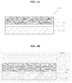
- FIGS. 4A and 4B are cross-sectional views illustrating electrode structures 400A and 400B according to other embodiments of the present invention.
- conductive layers CL may be disposed on surfaces of the electrode structures 100 and 200 having nonwoven structures obtained by using the afore-described method. Since the metal fibers 10 in the electrode structures 100 and 200 having the nonwoven structures function as current collectors, the conductive layers CL may be applied to a tap for assembling the battery.
- the conductive layer CL may be attached to the electrode structure 100 having the nonwoven structure by using a conductive adhesive layer AL, for example, a metal paste, as shown in FIG. 4A .
- a conductive adhesive layer AL for example, a metal paste
- the conductive layer CL as shown in FIG. 4B , may be bonded to the electrode structure 200 by using a bonding layer BL or a reaction layer through chemical bonding between the electrode structure 200 having the nonwoven structure and the conductive layer CL.
- the conductive layer CL may be a thin metal foil such as stainless steel, aluminum, or copper.
- FIG. 5A is an exploded perspective view illustrating a battery 1000 using electrode structures 100a and 100b, according to an embodiment of the present invention.
- FIG. 5B is a cross-sectional view for explaining a method of stacking the electrode structures 100a and 100b, according to an embodiment of the present invention.
- the battery 1000 may be a general cylindrical battery.
- the electrode structures 100a and 100b having different polarities which act for a cathode and an anode may be alternately wound around each other.
- Conductive taps 100T such as the conductive layers CL of FIGS. 4A and 4B may be respectively coupled to end portions of the electrode structures 100a and 100b.
- a separator 500 may be disposed between the electrode structures 100a and 100b.
- a current collector such as a conventional metal foil is not coated on at least one or all of the electrode structures 100a and 100b having different polarities
- ion exchange may occur in both directions between the electrode structures 100a and 100b during charging/discharging.
- the electrode structure 100b may be shared between one pair of adjacent electrode structures 100a.
- lithium ions of the electrode structure 100a move to both surfaces of the electrode structure 100b in directions marked by arrows A1 and A2 to emit energy. Even when the battery 1000 is charged, lithium ions move in both directions, thereby contributing to chemical reaction of the battery 1000.
- a thickness of an anode current collector is great, for example, when a thickness of the anode current collector is two times greater than a thickness of the electrically active material layer of the conventional electrode structure, the battery 1000 may have an equal or greater electrical capacity. Also, since the number of separators 500 used is less than that used when the conventional electrode is used, the battery 1000 having higher energy density may be provided.
- the separator 500 may be, for example, a polymer-based microporous film, a woven fabric, a non-woven fabric, ceramic, an intrinsic solid polymer electrolyte film, a gel solid polymer electrolyte film, or a combination thereof.
- the intrinsic solid polymer electrolyte film may include, for example, a straight chain polymer material or a crosslinked polymer material.
- the gel polymer electrolyte film may be any one of a plasticizer-containing polymer, a filler-containing polymer, or a pure polymer including salt or a combination thereof.
- the solid electrolyte layer may include, for example, a polymer matrix composed of any one of polyethylene, polypropylene, polyimide, polysulfone, polyurethane, polyvinyl chloride, polystyrene, polyethylene oxide, polypropylene oxide, polybutadiene, cellulose, carboxymethyl cellulose, nylon, polyacrylonitrile, polyvinylidene fluoride, polytetrafluoroethylene, a copolymer of vinylidene fluoride and hexafluoropropylene, a copolymer of vinylidene fluoride and trifluoroethylene, a copolymer of vinylidene fluoride and tetrafluoroethylene, polymethylacrylate, polyethylacrylate, polymethylmethacrylate, polyethylmethacrylate, polybutylacrylate, polybutylmethacrylate, polyvinyl acetate, polyvinyl alcohol, and a combination thereof, an additive, and an
- the materials of the separator 500 are exemplary, and any material that has an easily changeable shape, has a high mechanical strength, may not be broken or cracked even when the electrode structures 100a and 100b are deformed, has an arbitrary appropriate electron insulation, and excellent ion conductivity may be used.
- the separator 500 may be a single or multi-layered film, and the multi-layered film may be a stack of single-layered films formed of the same material or a stack of single-layered films formed of different materials.
- the stack may have a structure including a ceramic coating film on a surface of a polymer electrolyte film such as polyurefin.
- a thickness of the separator 500 may range from 10 ⁇ m to 300 ⁇ m, preferably, from 10 ⁇ m to 40 ⁇ m, and more preferably, from 10 ⁇ m to 25 ⁇ m.
- the battery 1000 is electrically connected to external electrode terminals 600 and 700 through the conductive taps 100T coupled to the electrode structures 100a and 100b.
- An aqueous electrolytic solution including salt such as potassium hydroxide (KOH), potassium bromide (KBr), potassium chloride (KCL), zinc chloride (ZnCl 2 ), or sulfuric acid (H 2 SO 4 ) in a housing 900 may be infiltrated into the electrode structures 100a and 100b and/or the separator 500, thereby completing the battery 1000.
- an appropriate battery management system for controlling stability and/or power supply characteristics while the battery 1000 is used may be additionally coupled.
- shapes of the electrode structures 100a and 100b including the metal fibers 10 are easily changed due to their characteristics as a fiber and an active material layer and a conductive network are substantially uniformly mixed in each of the overall electrode structures 100a and 100b, even when a thickness is increased in order to adjust a capacity of the battery 1000, performance of the battery 1000 may not be deteriorated unlike in the conventional electrode structure obtained by coating an active material layer on a metal foil, and thus any of various volumes may determine for the battery 1000.
- the electrode structures 100a and 100b including the metal fibers 100 may be easily changed, the electrode structures 100a and 100b may be three-dimensionally deformed, for example, being stacked, bent, and wrapped as well as being wound as shown in FIG. 5A , and the battery 1000 having any of various volumes and shapes, instead of a cylindrical shape, may be integrated with a an angular or pouch-like fibrous product such as clothes or bags Also, the electrode structures 100a and 100b may be applied to any one or all of a cathode and an anode of one battery.
- metal fibers that have excellent electrical, mechanical, and thermal characteristics which a metal has and flexibility and a structure which a fiber has, contact resistance between a current collector and electrically active materials may be reduced and a contact area may be increased, thereby improving energy density, charge/discharge speed, charge/discharge efficiency, and cycle characteristics of a battery.
- the battery may have excellent energy density per unit volume.
- a contact resistance between a current collector and electrically active materials may be reduced and a contact area may be increased, thereby improving energy density battery, charge/discharge speed, charge/discharge efficiency, and cycle characteristics of a battery.
- a conductive network including the metal fibers may reduce a change in volumes of the electrically active materials during charging/discharging, next-generation high efficiency Li intercalation materials may be used as the electrically active materials.
- the battery may have high energy density per unit volume.
- a method of manufacturing an electrode structure does not use a solvent such as water or an organic solvent in a process of forming a particle composition and a mixing process except in a process of pre-coating a binder, an environmental load may be reduced. Also, after the particle composition is infiltrated into a conductive network, since an additional dry process for removing the solvent in a slurry is not required, a process may be facilitated, productivity may be improved, and equipment may be simplified. When the solvent for the binder applied to the slurry remains on electrically active materials, the electrically active materials may be deteriorated. Accordingly, the mixing process using non-solvent dry powder may improve yield.
Abstract
Description
- This application claims the benefit of Korean Patent Application No.
10-2011-0031917, filed on April 6, 2011 - The present invention relates to a battery technology, and more particularly, to a battery having an electrode structure including metallic fibers and a method of fabricating the electrode structure.
- As a semiconductor fabricating technology and a communication technology have recently been developed, the mobile electronic device industry has expanded, and demands for environmental preservation and development of alternative energy due to resource depletion have increased, batteries have been actively studied. Batteries are classified into primary batteries that may be used only once for a predetermined period of time and secondary batteries that may be repeatedly used by being recharged. Lithium which is used as a material of a battery has advantages in that it is the lightest metal from among metals known in the nature system, has the lowest standard reduction potential, has high energy density when the battery is manufactured, and has a high voltage. Accordingly, studies of primary batteries and secondary batteries using lithium have been greatly spotlighted.
- Lithium primary batteries are often used as main power supply sources of portable electronic devices or backup power supply sources. Devices to which lithium secondary batteries are applied have been diversified from small devices such as mobile phones, notebooks, and mobile displays to medium and large devices for electric vehicles and hybrid vehicles.
- Accordingly, batteries are required to have high stability and cost effectiveness as well as lightweight and small design, high energy density, high charge/discharge speed, high charge/discharge efficiency, and excellent cycle characteristics.
- The present invention provides a battery including an electrode structure which has high energy density, charge/discharge speed, high charge/discharge efficiency, and excellent cycle characteristics and whose shape and capacity may be easily adjusted.
- The present invention also provides a method of fabricating the battery. According to an aspect of the present invention, there is provided a battery including an electrode structure, the battery including: a conductive network that is formed by using one or metal fibers; and a particle composition including electrically active materials that are provided as particles and are bound to the conductive network.
- The one or more metal fibers may be bonded to one another by randomly only physically contacting one another, and the conductive network has a nonwoven structure. The particle composition may further include any one or all of a conductor, a binder, and porous ceramic particles. The binder may be provided as a point binder between the one or more metal fibers and the electrically active materials, and between the electrically active materials.
- Each of the one or more metal fibers may have a thickness ranging from 1 µm to 200 µm. Each of the one or more metal fibers may have a thickness ranging from 2 µm to 20 µm. The one or more metal fibers may include any one of stainless steel, aluminum, nickel, titanium, copper, an alloy thereof, or a combination thereof. A ratio of an average size of the electrically active materials to an average thickness of the one or more metal fibers may range from 0.01 to 10.
- According to another aspect of the present invention, there is provided a method of manufacturing an electrode structure, the method including: providing one or more metal fibers that constitute a conductive network; providing a particle composition that includes electrically active materials which are particles; mixing the one or more metal fibers with the particle composition to obtain a mixture; and compressing the mixture of the one or more metal fibers and the particle composition.
- The one or more metal fibers may be provided as a fiber layer having a nonwoven structure by being randomly arranged. The mixing may include disposing the particle composition as non-solvent dry powder on the fiber layer. The mixing may include mixing the one or more metal fibers with the particle composition by spraying the particle composition into the conductive network.
- The particle composition may include external additives selected from any one of binder particles, conductor particles, porous ceramic particles which are mixed along with the electrically active materials, and a combination thereof, wherein the external additives are mixed with the electrically active materials by using a dry mixing process.
- The providing of the one or more metal fibers may include pre-coating a binder on surfaces of the one or more metal fibers. The particle composition may include external additives selected from any one of conductor particles and porous ceramic particles which are mixed along with the electrically active materials, and a combination thereof, wherein the external additives are mixed with the electrically active materials by using a dry mixing process.
- The particle composition may include external additives selected from any one of conductor particles and porous ceramic particles which are mixed along with the electrically active materials, and a combination thereof, and a binder is pre-coated on surfaces of any one or both of the conductor particles and the porous ceramic particles, wherein the external additives are mixed with the electrically active materials by using a dry mixing process.
- The method may further include performing heating or emitting ultraviolet rays at the same time as the compressing.
- The above and other features and advantages of the present invention will become more apparent by describing in detail exemplary embodiments thereof with reference to the attached drawings in which:
-
FIGS. 1A to 1C are views illustrating electrode structures according to embodiments of the present invention; -
FIG. 2 is a flowchart illustrating a method of fabricating any of the electrode structures ofFIGS. 1A to 1C , according to an embodiment of the present invention; -
FIGS. 3A to 3D are views sequentially illustrating resultant structures of the method ofFIG. 2 ; -
FIGS. 4A and 4B are cross-sectional views illustrating electrode structures according to other embodiments of the present invention; -
FIG. 5A is an exploded perspective view illustrating a battery using electrode structures, according to an embodiment of the present invention; and -
FIG. 5B is a cross-sectional view for explaining a method of stacking the electrode structures, according to an embodiment of the present invention. - The present invention will now be described more fully with reference to the accompanying drawings, in which exemplary embodiments of the invention are shown.
- The present invention now will be described more fully hereinafter with reference to the accompanying drawings, in which elements of the invention are shown. The present invention may, however, be embodied in many different forms and should not be construed as limited to the exemplary embodiments set forth herein. Rather, these embodiments are provided so that this disclosure will be thorough and complete, and will fully convey the scope of the present invention to one of ordinary skill in the art.
- Also, in the drawings, thicknesses or sizes of layers are exaggerated for convenience of explanation and clarity, and the same reference numerals denote the same elements. As used herein, the term "and/or" includes any and all combinations of one or more of the associated listed items.
- The terminology used herein is for the purpose of describing particular embodiments only and is not intended to be limiting of exemplary embodiments of the present invention. As used herein, the singular forms "a", "an" and "the" are intended to include the plural forms as well, unless the context clearly indicates otherwise. It will be further understood that the terms "comprises", "comprising,", "includes" and/or "including", when used herein, specify the presence of stated features, integers, steps, operations, elements, and/or components, but do not preclude the presence or addition of one or more other features, integers, steps, operations, elements, components, and/or groups thereof.
- It will be understood that, although the terms first, second, third etc. may be used herein to describe various elements, components, regions, layers, and/or sections, these elements, components, regions, layers, and/or sections should not be limited by these terms. These terms are only used to distinguish one element, component, region, layer, or section from another region, layer, or section. Thus, a first element, component, region, layer, or section discussed below could be termed a second element, component, region, layer, or section without departing from the teachings of exemplary embodiments.
- A long metal fiber used herein which is obtained by fiberizing a metal such as stainless steel, aluminum, nickel, titanium, copper, or an alloy thereof refers to a metal thread having a diameter ranging from several micrometers (µm) to tens of µm and a length equal to or greater than tens of µm. The long metal fiber has heat resistance, plasticity, and electrical conductivity like a metal, and also may be woven or nonwoven like a fiber. The present invention relates to an electrode structure of a battery using the advantages of the long metal fiber.
- Such long metal fibers may be manufactured by maintaining a molten metal or alloy in a container and rapidly solidifying the molten metal or alloy by spraying the molten metal or alloy into the air through discharge holes in the container by using a pressure means such as a piston or a compressed gas. Alternatively, the long metal fibers may be manufactured by using a well-known bundle drawing method. Thicknesses, uniformity, a structure such as a nonwoven structure, and an aspect ratio of the long metal fibers may be controlled by controlling the number of the discharge holes, sizes of the discharge holes, and/or the flight of the molten metal. The long metal fibers constituting the battery may be manufactured as described above or may be manufactured by using any of other well-known methods without departing from the scope of the present invention.
- When the term 'separator' is used herein, the separator includes a separator that is generally used in a liquid electrolyte battery using a liquid electrolyte having low affinity with the separator. Furthermore, when the separator used herein includes an intrinsic solid polymer electrolyte and/or a gel solid polymer electrolyte which is so strongly bound to the separator that the electrolyte and the separator are recognized as the same. Accordingly, the meaning of the separator has to be defined as described herein.
-
FIGS. 1A to 1C are views illustratingelectrode structures - Referring to
FIGS. 1A to 1C , each of theelectrode structures more metal fibers 10 and electricallyactive materials 20. Themetal fibers 10 may have plasticity due to ductility and malleability of a metal. Also, a plurality of themetal fibers 10 each having an appropriate length may be provided by being segmented. The number of themetal fibers 10 may be appropriately determined according to a size and a capacity of a battery. - Each of the
metal fibers 10 may have a thickness ranging from 1 µm to 200 µm. When a thickness of each of themetal fibers 10 is equal to or less than 1 µm, it may be difficult to shape themetal fibers 10 to have uniform properties, and may be difficult to arbitrarily arrange themetal fibers 10 to form a conductive network as will be described below. Also, when a thickness of each of themetal fibers 10 is equal to or greater than 200 µm, since a surface area per volume of themetal fibers 10 is reduced, it may be difficult to improve the performance of the battery by increasing surface area. Since a binding force of the electricallyactive materials 20 is reduced, the electricallyactive materials 20 may be separated from each of theelectrode structures metal fibers 10 may have a thickness ranging from 2 µm to 20 µm. In this case, a ratio of a surface area to a volume per unit length (for example, 4/diameter when the battery has a circular cross-sectional shape) may be 4x10⁵ (1/m) to 2x10⁶ (1/m). - In general, a conventional current collector using a foil has a thickness of about 20 µm. When the
metal fibers 10 each having a thickness ranging from 2 µm to 20 µm instead of the conventional current collector using a foil having a thickness of 20 µm is used, a surface area may be increased by about 4 times to 40 times. Accordingly, a surface area when a current collector having metal fibers is used may be greater than a surface area when a conventional collector having a foil is used, assuming that the conventional collect and the current collect have the same weight. As such, according to the present embodiment, a surface area of a current collector may be easily adjusted by adjusting a thickness of each of themetal fibers 10. A surface area of a current collector refers to a surface area of a conductive network per volume of themetal fibers 10 that form reaction interfaces with each of the electricallyactive materials 20 and anelectrolytic solution 30. The battery having very high energy density may be formed by maximizing the surface area. - In some embodiments, an average length of the
metal fibers 10 may range from 5 mm to 1000 mm. In this case, an average aspect ratio of themetal fibers 10 may range from 25 to 106. If necessary, themetal fibers 10 are used for each of theelectrode structures - As to the thermal characteristics, the electrically
active materials 20 bound to the conductive network may be sintered by using thermal treatment. In this case, the electricallyactive materials 20 may be further strongly bonded to themetal fibers 10. It is impossible to perform such a sintering process on a conventional electrode structure using conductive polymer fibers. - Alternatively, in the conductive network including the
metal fibers 10, themetal fibers 10 may physically contact one another without being chemically bonded to one another through sintering. The present inventors have found that the conductive network in which themetal fibers 10 physically contact one another without being chemically bonded to one another suffers less performance degradation during often charging/discharging. This is because when themetal fibers 10 simply physically contact one another without being chemically bonded to one another, the conductive network may more flexibly respond to a volume change during charging/discharging. - Although the
metal fibers 10 illustrated inFIGS. 1A to 1C have substantially linear and curved shapes, the present embodiment is not limited thereto. Themetal fibers 10 may have other regular or irregular shapes such as curled shapes or spiral shapes. Themetal fibers 10 having linear shapes, curved shapes, or other regular/irregular shapes are electrically connected to one another in each of theelectrode structures metal fibers 10 are curved, bent, tangled, contact, or bonded to one another, pores may be formed therein, high mechanical strength may be ensured, and flexibility due to fiber characteristics may be obtained. - The
metal fibers 10 may include any one of stainless steel, aluminum, nickel, titanium, copper, an alloy thereof, or a combination thereof. For example, in the case of a cathode, themetal fibers 10 may include aluminum or an alloy thereof which is not oxidized in a high potential area. In the case of an anode, the metalthin films 10 may include copper, stainless steel, nickel, or an alloy thereof which is electrochemically inactive at a low operational potential. - The metals are exemplary, and other appropriate metal materials which are stable and are not oxidized and reduced for each electrode may be used. Also, if necessary, the
metal fibers 10 may include two or more different types of metals, and may be chemically bonded to one another by forming an intermetallic compound therebetween by using an additional process such as thermal treatment or sintering. - The electrically
active materials 20 are bound in the conductive network including themetal fibers 10. In order for the electricallyactive materials 20 to be strongly bound to the conductive network, sizes of pores in the conductive network including themetal fibers 10 and porosity may be appropriately adjusted. The sizes of the pores and the porosity may be adjusted by adjusting a mixture ratio by weight between the electricallyactive materials 20 and themetal fibers 10 in theelectrode structure 100. - In some embodiments, the mixture ratio by weight of the
metal fibers 10 in theelectrode structure 100 may be adjusted by increasing the number or length of themetal fibers 10. Alternatively, the sizes of the pores and the porosity in theelectrode structure 100 may be appropriately adjusted by mechanically compressing a mixture of themetal fibers 10 and the electricallyactive materials 20 by using a pressure device such as a roll press. Due to the compression, the conductive network having a nonwoven structure may be mechanically further strengthened, and the electricallyactive materials 20 are strongly bound to the conductive network, thereby improving energy density of a battery. - The electrically
active materials 20 may be particles having an average size ranging from 0.1 µm to 100 µm. The electricallyactive materials 20 may have a particle-size distribution of a predetermined range, and if necessary, the particle-size distribution of the electricallyactive materials 20 may be controlled by using a classification process. In some embodiments, the electricallyactive materials 20 may have an average size ranging from 0.1 µm to 15 µm. As described above, assuming that the conductive network includes themetal fibers 10 each having a thickness ranging from 1 µm to 200 µm, it is desirable that a size s of each of the electricallyactive materials 20 which are bound to the conductive network corresponds to a thickness d of each of themetal fibers 10. In this case, the electricallyactive materials 20 may be well bound in the conductive network. In some embodiments, a ratio s/d of the average size s of each of the electricallyactive materials 20 which are particles to the thickness d of each of themetal fibers 10 may range from 0.1 to 10. When the ratio s/d is less than 0.01, the electricallyactive materials 20 may drop into theelectrolytic solution 30, and when the ratio s/d is equal to or greater than 10, a reduction in a volume change and improvement in electrical conductivity due to the conductive network may be reduced. - Since the electrically
active materials 20 are provided as particles by being segmented, battery deterioration due to a change in a stress applied to electricallyactive materials 20 during an oxidation/reduction cycle, especially, the electricallyactive materials 20 for an anode, may be suppressed or reduced. Also, since themetal fibers 20 pass through between the electricallyactive materials 20 which are provided as particles, each of theelectrode structures - In detail, when the battery is a Li ion battery which is a representative secondary battery, a volume of the electrically
active materials 20 for a high-capacity anode may be increased 100% or more during lithiation. In this case, during an electrochemical charge/discharge cycle, an anode is repeatedly expanded and contracted, and thus may be cracked. In a conventional structure in which the electricallyactive materials 20 are coated on a current collector, due to the cracks, when the electricallyactive materials 20 no longer electrically contact the current collector, electrical conductivity between the electricallyactive materials 20 may be reduced, a capacity may be drastically reduced, irreversibility may be increased, and the risk of instability may be increased. - However, in each of the
electrode structures metal fibers 10 and the electricallyactive materials 20 reduce a change in volumes of the electricallyactive materials 20 during charging/discharging, cracks may not occur in the electricallyactive materials 20. Since the electricallyactive materials 20 which are particles are still bonded to themetal fibers 10, a reduction in electrical conductivity which may occur when the electricallyactive materials 20 are separated from one another may be prevented, thereby improving reversibility between charge/discharge. - In order to address cracks in an electrode due to a change in a volume of an anode during charging/discharging, a nanoscale electrode structure which is less vulnerable to a change in volume or cracks, for example, nanowires, nanotubes, or nanorods, have recently been suggested. However, the nanoscale electrode structure may be for a small battery and may not be applied to a high-capacity large battery, and requires a complex fabricating process such as catalytic reaction. Also, in order to coat electrically active materials on the nanoscale electrode structure, a complex process such as vacuum deposition needs to be performed. However, according to the present embodiment, since a size and a shape of the electrode structure may be more easily changed than the conventional nanoscale electrode structure, the battery may be used as a small battery or a medium or large battery having high capacity. Also, the battery having any of various shapes and functions may be manufactured at low costs by using a stacking or mixing process as will be described below.
- The electrically
active materials 20 which are particles and bound in the conductive network may be appropriately determined according to a polarity of the electrode structure and whether the battery is a primary battery or a secondary battery. For example, the electricallyactive materials 20 for a cathode may be selected from the group consisting of oxide, phosphate, sulfide, fluoride, each of which includes two or more components selected from lithium, nickel, cobalt, chromium, magnesium, strontium, vanadium, lanthanum, cerium, iron, cadmium, lead, titanium, molybdenum, and/or manganese, and a combination thereof. However, the present embodiment is not limited thereto, and the electricallyactive materials 20 for a cathode may be formed of another chalcogen compound. Preferably, the electricallyactive materials 20 for a cathode may be a lithium compound including three or more components, that is, a lithium compound including at least two of cobalt, copper, nickel, manganese, titanium, and molybdenum which are suitable for a lithium secondary battery and including at least one nonmetal element selected from the group consisting of oxygen (O), fluorine (F), sulfur (S), phosphorus (P), and a combination thereof. - The electrically
active materials 20 for an anode may be a carbon-based material, for example, a low-crystallized carbon-based material or a high-crystallized carbon-based material. The low-crystallized carbon may be, for example, soft carbon or hard carbon. The high-crystallized carbon may be high temperature baked carbon such as natural graphite, Kish graphite, pyrolytic carbon, mesophase pitch-based carbon fiber, meso-carbon microbeads, mesophase pitches, or petroleum or coal tar pitch-derived cokes. The materials are exemplary, and other carbon-based materials such as diamond-based materials and carbyne-based materials may also be used. - In other embodiments, the electrically
active materials 20 for an anode may include at least one of sodium or another oxide, carbide, nitride, sulfide, phosphide, selenium, and tellurium which are suitable for a NaS battery, instead or or along with the above carbon-based materials. Alternatively, the electricallyactive materials 20 for an anode may include a single atom-based material such as silicon, geranium, tin, lead, antimony, bismuth, zinc, aluminum, iron, or cadmium which may absorb and emit high-capacity lithium ions for a high-capacity cathode, an intermetallic compound thereof, or a non-carbon-based active material such as an oxide-based material. - In other embodiments, since the conductive network provides buffering action to a change in a volume of the electrically
active materials 20, the electricallyactive materials 20 may include a metal-based compound or an intermetallic compound whose capacity is high and whose volume change is large such as silicon (Si), bismuth (Bi), tin (Sn), aluminum (Al), or an alloy thereof which is considered as a next-generation high efficiency Li intercalation material. - In some embodiments, as shown in the
electrode structure 200 ofFIG. 1B , a binder 40 may be added such that the electricallyactive materials 20 which are particles may be strongly bound to the conductive network. The binder may be a polymer-based material such as vinylidene fluoride-hexfluoropropylene copolymer (PVDF-co-HFP), polyvinylidenefluoride (PVDF), polyacrylonitrile, polymethylmethacrylate, polytetrafluoroethylene (PTFE), styrenebutadiene rubber (SBR), polyimide, polyurethane-based polymer, polyester-based polymer, or ethylene-propylene-diene copolymer (EPDM). If necessary, the binder may be, but is not limited to, another polymer-based material having conductivity such as petroleum pitch or coal tar. The present embodiment is not limited to the materials, and the binder may be formed of any material that has stability and a predetermined binding force under an electrochemical environment and may not be dissolved in an electrolyte. -
Binders binders active materials 20 and thebinders binders binders binders active materials 20 which are particles are strongly bound in the conductive network in theelectrode structure 200, the use of the binder 40 may be minimized. Also, when thebinders binders - When the use of the
binders active materials 20 which are particles, and between the electricallyactive materials 20 and themetal fibers 10. The point binder may minimize an increase in internal resistance of theelectrode structure 200. A method of fabricating various electrode structures for inducing the point binder will be described below. - When the electrically
active materials 20 are electrically active materials for a cathode, aconductor 50 may be further added along with the electricallyactive materials 20 and thebinders electrode structure 300 as shown inFIG. 1C . Theconductor 50 may be uniformly mixed with the electricallyactive materials 20 and may be provided into theelectrode structure 300. Theconductor 50 may be added such that a weight of theconductor 50 ranges from about 1% to about 15% with respect to a total weight of a mixture of the electricallyactive materials 20 and theconductor 50. - The
conductor 50 may be a nanostructure having a high specific surface area and low resistance such as , a nano metal particle paste, an indium tin oxide (ITO) paste, carbon nanotubes, or fine carbon such as carbon black, acetylene black, ketjen black, or ultrafine graphite particles. Since themetal fibers 10 having a micro size corresponding to theactive materials 20 may function as theconductor 50 in theelectrode structure 300, an increase in fabricating costs due to the addition of theconductor 50 may be prevented. - In other embodiments, although not shown in
FIGS. 1 to 3 , porous ceramic particles may be further added into theelectrode structure electrolytic solution 30 to be impregnated into each of theelectrode structures - As described above, since the
metal fibers 10 have shapability which a fiber has and a mechanical strength, high conductivity, and thermal stability which a metal has, an electrode structure including themetal fibers 10 may improve capacity, energy density, and charge/discharge efficiency. It would be understood by one of ordinary skill in the art that the present invention may be more efficiently applied to a battery which requires high capacity and high charge/discharge speed such as a battery for starting, lighting, and igniting (SLI) a vehicle, a battery for driving an electric vehicle and a hybrid vehicle, or a fixed battery for storing green energy. - Also, due to characteristics of a fiber, that is, flexibility, of each of the
electrode structures -
FIG. 2 is a flowchart illustrating a method of fabricating any of theelectrode structures FIGS. 1A to 1C , according to an embodiment of the present invention.FIGS. 3A to 3D are views sequentially illustrating resultant structures of the method ofFIG. 2 . - Referring to
FIG. 2 , in operation S100, themetal fibers 10 are prepared. A plurality of themetal fibers 10 each having a predetermined length may be provided by being segmented. In order to form an electrode structure having a nonwoven structure, themetal fibers 10 may be segmented to have a length ranging from about 5 cm to about 8 cm. As shown inFIG. 3A , themetal fibers 10 may be randomly arranged on an appropriate support plane. In this case, themetal fibers 10 may be stacked to a thickness of a single layer or several to hundreds of layers, thereby providing afirst fiber layer 10L1. - In some embodiments, the
metal fibers 10 may be deformed by tapping themeal fibers 10 with a bar, and due to the deformation, themetal fibers 10 may be tangled with one another to form a nonwoven structure. Themetal fibers 10 in thefirst fiber layer 10L1 physically contact one another to form a conductive network which is somewhat sparse. Selectively, through appropriate thermal treatment, themetal fibers 10 may be chemically bonded to one another. In this case, the thermal treatment may be performed at a temperature ranging from, for example, 100°C to 1200°C. - In some embodiments, electrically active materials may be uniformly pre-coated on the
metal fibers 10 by using a binder. To this end, themetal fibers 10 on which the electrically active materials are pre-coated may be obtained by dispersing a mixed composition of electrically active material particles and a binder in an appropriate solvent to obtain a resultant structure, dipping themetal fibers 10 in the resultant structure, removing the solvent by using a dry process. The electrically active materials to be pre-coated may be the same as the electricallyactive materials 20 to be infiltrated in the conductive network or a different type of active materials having chemical affinity with the electricallyactive materials 20. Alternatively, in order to prevent corrosion of themetal fibers 10 due to an electrolytic solution, the electrically active materials to be pre-coated may include another metal or metal oxide coated body having corrosion resistance. - Next, in operation S200, a particle composition including the electrically
active materials 20 to be subjected to battery reaction is prepared. The electricallyactive materials 20 may be particles each having a size ranging from 0.1 µm to 100 µm as described above. The particle composition may include an external additive selected from any one of a binder, a conductor, and porous ceramic particles or a combination thereof, in addition to the electricallyactive materials 20. - When at least one of a binder, a conductor, and porous ceramic particles is further included as an additive in the particle composition, the particle composition may be provided by using a dry mixing process. For example, an intermediate mixed particle composition is formed by rotating the electrically
active materials 20 which are particles and a predetermined quantity of conductor particles at a high speed by using mixer. Next, solid binder particles are added to the dried intermediate mixed composition and are rotated at a high speed by using the mixer, thereby completing the particle composition. The intermediate mixed particle composition and the particle composition obtained by using the mixing process are non-solvent dry powder which is mixed without using a solvent. - Alternatively, an intermediate mixed particle composition may be formed by introducing binder particles into a mixer along with electrically
active materials 20, and rotating the same at a high speed. Next, a conductor may be added to the intermediate mixed particle composition and mixed again, thereby completing the particle composition. Alternatively, the particle composition may be formed by simultaneously adding binder particles and conductor particles to the electricallyactive materials 20, and rotating the same at a high speed by using a mixer. Even in this case, the intermediate mixed particle composition and the particle composition are non-solvent dry powder. - When the porous ceramic particles are added to the particle composition, the porous ceramic particles may be mixed with other materials, that is, any one of binder particles and a conductor, or electrically active material particles. For example, an intermediate mixed particle composition may be formed by mixing the electrically active material particles, the binder particles, and conductor particles to obtain a resultant structure, and a particle composition may be formed by adding the porous ceramic particles to the resultant structure and mixing the same. Even in this case, the particle composition is non-solvent dry powder.
- In the above embodiments, a binder is provided as particles. However, in other embodiments, selectively, the binder may be provided by being pre-coated on surfaces of any one of metal fibers, conductor particles, and porous ceramic particles. To this end, metal fibers on which a binder is pre-coated may be obtained by dipping the metal fibers in a solution in which the binder is dissolved or dispersed, taking out the metal fibers after a predetermined period of time, drying the solvent by using a drier or the like. Alternatively, metal fibers on which a binder is pre-coated may be obtained by dipping the metal fibers in a solvent in which the binder is dissolved or dispersed, and stirring the solution to dry the solvent.
- Likewise, conductor particles and/or porous ceramic particles on surfaces of which a binder is pre-coated may be obtained by putting any one or all of the conductor particles and the porous ceramic particles in a solvent in which the binder is dissolved or dispersed, and stirring the solution to dry the solvent. In the above embodiments, since the binder is used by being pre-coated, an environmental load may be lower than that in a conventional fabricating process which forms a slurry by mixing a large quantity of active materials and a binder in a solvent.
- As described above, when a binder is pre-coated on surfaces of metal fibers, conductor particles, or porous ceramic particles, a process of adding binder particles when a particle composition is formed may be omitted. As such, when a binder is provided by being pre-coated on metal fibers or additives such as conductor particles or porous ceramic particles, a distribution and a content of the binder in an overall electrode composition may be reasonably controlled. Although attempts to pre-coat a binder on electrically active material particles may be made, a point binder may not be induced when heating is performed at a temperature at which the binder is melted in a compression process, and a battery's electrical characteristics may be deteriorated due to an increase in the amount of the binder added. Accordingly, a binder may be pre-coated only on surfaces of metal fibers, conductor particles, or porous ceramic particles, and may not be pre-coated on electrically active material particles.
- As will be described below, since a process of forming an electrode is performed at a relatively low temperature at which a binder may be melted, for example, at a temperature ranging from 50°C to 400°C, and preferably, at a temperature ranging from 150°C to 300°C, the binder may be maintained at its pre-coated position, and the
binders metal fibers 10 and the electricallyactive materials 20 and between the electricallyactive materials 20 and theconductors 50, and further between the electricallyactive materials 20 as shown inFIG. 1B by being expanded and contracted due to some heat supplied while the electrode is fabricated. Since the binder does not contribute to electrical characteristics except that it has lithium ion conductivity, it is preferable that the use of the binder in the electrode structure is minimized as described above. - After the particle composition is formed in operation S200, the method proceeds to operation S300. In
operation 300, themetal fibers 10 and the particle composition are mixed. When themetal fibers 10 are provided as the first fiber layer 10L1, preferably, as a layer having a metal nonwoven structure, as shown inFIG. 3B , the particle composition may be sprayed onto thefirst fiber layer 10L1 such that themetal fibers 10 and the particle composition are mixed with each other. Referring toFIG. 3B , aparticle composition 20L is infiltrated into thefirst fiber layer 10L1 and part of the particle composition remains on thefirst fiber layer 10L1. The resultant structure ofFIG. 3B is exemplary, and the present embodiment is not limited thereto. For example, an appropriate amount of particle composition may be mixed such that the particle composition may be completely infiltrated into thefirst fiber layer 10L1. - In some embodiments, uniformity of the particle composition infiltrated into the
first fiber layer 10L1 may be improved by spraying the particle composition onto a top surface of thefirst fiber layer 10L1, turning over a resultant structure, and also spraying the particle composition onto a bottom surface of thefirst fiber layer 10L1 which is exposed. If necessary, during operation S300, in order to promote to uniformly infiltrate the particle composition into pores between themetal fibers 10, an oscillation may be applied at an appropriate frequency with an appropriate strength. - In some embodiments, a
second fiber layer 10L2 may be further disposed on the resultant structure as shown inFIG. 3C . Thesecond fiber layer 10L2 may be formed in a similar manner to that used to form thefirst fiber layer 10L1. Thesecond fiber layer 10L2 may have a thickness of a single layer or several to hundreds of layers. Themetal fibers 10 may be deformed by patting themetal fibers 10 by using a bar, and thus themetal fibers 10 may be tangled with one another to form a nonwoven structure. - In some embodiments, the operations described with reference to
FIGS. 3A to 3C may be repeatedly performed. For example, as shown inFIG. 3D , a process of forming a plurality offiber layers 10L1, 1OL2, and 10L3 and a process of forming electricallyactive material layers active materials 20 may be alternately performed several times. Although threefiber layers active material layers FIG. 3D , the present embodiment is not limited thereto. For example, twofiber layers active material layer 20L may be alternately stacked as shown inFIG. 3C , or four or more fiber layers and three or more electrically active material layers may be alternately stacked. - Referring back to
FIG. 3D , when operation S300 ends, the method proceeds to operation S400. In operation S400, astructure 400 obtained by mixing themetal fibers 10 and the particle composition is compressed. Due to operation S400, thestructure 400 may have a planar shape having a predetermined thickness. Operation S400 may be performed by using a roll press, and may improve capacity density of the electrode and adhesion between the conductive network and the electricallyactive materials 20. - If necessary, for example, when binder particles or a pre-coated binder is included in the resultant structure, during operation S400, energy for melting the binder may be applied to the resultant structure. The energy may be heat and/or ultraviolet rays. The energy may be appropriately determined according to a type of the binder, and generally heating may be performed at a relatively low temperature, for example, a temperature ranging from 50°C to 400°C, and preferably, from 150°C to 300°C.
- In operation S400, a surface of the
structure 400 may be compressed in directions marked by arrows. Accordingly, themetal fibers 10 in adjacent fiber layers, for example, in thefirst fiber layer 10L1 and thesecond fiber layer 10L2, and in thesecond fiber layer 10L2 and thethird fiber layer 10L3 may be tangled with each other to physically contact each other, thereby forming a conductive network over theentire structure 400. - Unlike a conventional method of fabricating an electrode using a metal foil, the method of fabricating the electrode structure described with reference to
FIGS. 2 to 3D provides a particle composition as non-solvent dry powder, instead of a slurry. That is, in the above embodiments, the electricallyactive materials 20 are infiltrated as dry particles without a solvent into the conductive network of themetal fibers 10. - Accordingly, according to the embodiments of the present invention, since a solvent such as water or an organic solvent is not used except in a process of pre-coating a binder, an environmental load may be reduced. Also, after a particle composition is infiltrated into a conductive network, since a dry process of removing a slurry in the solvent is not required, a process may be facilitated, productivity may be improved, and equipment may be simplified. Also, when a solvent for a binder used in a slurry remains on the electrically
active materials 20, the electricallyactive materials 20 may be deteriorated. Accordingly, a mixing process using non-solvent dry powder may improve yield. -
FIGS. 4A and 4B are cross-sectional views illustratingelectrode structures - Referring to
FIGS. 4A and 4B , conductive layers CL may be disposed on surfaces of theelectrode structures metal fibers 10 in theelectrode structures - The conductive layer CL may be attached to the
electrode structure 100 having the nonwoven structure by using a conductive adhesive layer AL, for example, a metal paste, as shown inFIG. 4A . Alternatively, the conductive layer CL, as shown inFIG. 4B , may be bonded to theelectrode structure 200 by using a bonding layer BL or a reaction layer through chemical bonding between theelectrode structure 200 having the nonwoven structure and the conductive layer CL. The conductive layer CL may be a thin metal foil such as stainless steel, aluminum, or copper. -
FIG. 5A is an exploded perspective view illustrating abattery 1000 usingelectrode structures FIG. 5B is a cross-sectional view for explaining a method of stacking theelectrode structures - Referring to
FIG. 5A , thebattery 1000 may be a general cylindrical battery. In order to increase a reaction area, theelectrode structures FIGS. 4A and 4B may be respectively coupled to end portions of theelectrode structures - Referring to
FIGS. 5A and 5B , in order to insulate theelectrode structures separator 500 may be disposed between theelectrode structures electrode structures electrode structures first electrode structure 100a is for a cathode and thesecond electrode structure 100b is for an anode and a conventional current collector is not applied to theelectrode structure 100b for an anode, theelectrode structure 100b may be shared between one pair ofadjacent electrode structures 100a. Accordingly, while thebattery 1000 is discharged, lithium ions of theelectrode structure 100a move to both surfaces of theelectrode structure 100b in directions marked by arrows A1 and A2 to emit energy. Even when thebattery 1000 is charged, lithium ions move in both directions, thereby contributing to chemical reaction of thebattery 1000. - An electrical capacity decreases as a thickness of an electrically active material layer in a conventional electrode structure including a metal foil-type current collector and electrically active materials that are coated on the metal foil-type current collector increases. However, in
FIG. 5B , even when a thickness of an anode current collector is great, for example, when a thickness of the anode current collector is two times greater than a thickness of the electrically active material layer of the conventional electrode structure, thebattery 1000 may have an equal or greater electrical capacity. Also, since the number ofseparators 500 used is less than that used when the conventional electrode is used, thebattery 1000 having higher energy density may be provided. - The
separator 500 may be, for example, a polymer-based microporous film, a woven fabric, a non-woven fabric, ceramic, an intrinsic solid polymer electrolyte film, a gel solid polymer electrolyte film, or a combination thereof. The intrinsic solid polymer electrolyte film may include, for example, a straight chain polymer material or a crosslinked polymer material. The gel polymer electrolyte film may be any one of a plasticizer-containing polymer, a filler-containing polymer, or a pure polymer including salt or a combination thereof. The solid electrolyte layer may include, for example, a polymer matrix composed of any one of polyethylene, polypropylene, polyimide, polysulfone, polyurethane, polyvinyl chloride, polystyrene, polyethylene oxide, polypropylene oxide, polybutadiene, cellulose, carboxymethyl cellulose, nylon, polyacrylonitrile, polyvinylidene fluoride, polytetrafluoroethylene, a copolymer of vinylidene fluoride and hexafluoropropylene, a copolymer of vinylidene fluoride and trifluoroethylene, a copolymer of vinylidene fluoride and tetrafluoroethylene, polymethylacrylate, polyethylacrylate, polymethylmethacrylate, polyethylmethacrylate, polybutylacrylate, polybutylmethacrylate, polyvinyl acetate, polyvinyl alcohol, and a combination thereof, an additive, and an electrolytic solution. The materials of theseparator 500 are exemplary, and any material that has an easily changeable shape, has a high mechanical strength, may not be broken or cracked even when theelectrode structures - The
separator 500 may be a single or multi-layered film, and the multi-layered film may be a stack of single-layered films formed of the same material or a stack of single-layered films formed of different materials. For example, the stack may have a structure including a ceramic coating film on a surface of a polymer electrolyte film such as polyurefin. Considering durability, shut-down function, and stability of thebattery 1000, a thickness of theseparator 500 may range from 10 µm to 300 µm, preferably, from 10 µm to 40 µm, and more preferably, from 10 µm to 25 µm. - The
battery 1000 is electrically connected toexternal electrode terminals conductive taps 100T coupled to theelectrode structures electrode structures separator 500, thereby completing thebattery 1000. Although not shown inFIGS. 5A and 5B , an appropriate battery management system for controlling stability and/or power supply characteristics while thebattery 1000 is used may be additionally coupled. - Since shapes of the
electrode structures metal fibers 10 are easily changed due to their characteristics as a fiber and an active material layer and a conductive network are substantially uniformly mixed in each of theoverall electrode structures battery 1000, performance of thebattery 1000 may not be deteriorated unlike in the conventional electrode structure obtained by coating an active material layer on a metal foil, and thus any of various volumes may determine for thebattery 1000. - Also, since shapes of the
electrode structures metal fibers 100 may be easily changed, theelectrode structures FIG. 5A , and thebattery 1000 having any of various volumes and shapes, instead of a cylindrical shape, may be integrated with a an angular or pouch-like fibrous product such as clothes or bags Also, theelectrode structures - According to the embodiments, since metal fibers that have excellent electrical, mechanical, and thermal characteristics which a metal has and flexibility and a structure which a fiber has, contact resistance between a current collector and electrically active materials may be reduced and a contact area may be increased, thereby improving energy density, charge/discharge speed, charge/discharge efficiency, and cycle characteristics of a battery.
- Also, since a current collector using fibers having a nonwoven structure instead of a current collector using an existing foil is used, the number of separators used to manufacture a battery by stacking electrodes may be reduced. As a result, since an electrode may be manufactured to have a great thickness in the same volume, the battery may have excellent energy density per unit volume.
- According to the one or more embodiments of the present invention, since metal fibers which have excellent electrical, mechanical, and thermal characteristics which a metal has and flexibility and a structure which a fiber has, a contact resistance between a current collector and electrically active materials may be reduced and a contact area may be increased, thereby improving energy density battery, charge/discharge speed, charge/discharge efficiency, and cycle characteristics of a battery. Also, since a conductive network including the metal fibers may reduce a change in volumes of the electrically active materials during charging/discharging, next-generation high efficiency Li intercalation materials may be used as the electrically active materials. Also, since a current collector using fibers having a nonwoven fabric instead of a current collector using an existing foil is used, the number of separators used to form a battery by stacking electrodes may be reduced. As a result, since an electrode may be manufactured to have a great thickness in the same battery volume, the battery may have high energy density per unit volume.
- Also, since a method of manufacturing an electrode structure does not use a solvent such as water or an organic solvent in a process of forming a particle composition and a mixing process except in a process of pre-coating a binder, an environmental load may be reduced. Also, after the particle composition is infiltrated into a conductive network, since an additional dry process for removing the solvent in a slurry is not required, a process may be facilitated, productivity may be improved, and equipment may be simplified. When the solvent for the binder applied to the slurry remains on electrically active materials, the electrically active materials may be deteriorated. Accordingly, the mixing process using non-solvent dry powder may improve yield.
- While the present invention has been particularly shown and described with reference to exemplary embodiments thereof, it will be understood by those of ordinary skill in the art that various changes in form and details may be made therein without departing from the spirit and scope of the present invention as defined by the following claims.
Claims (18)
- A battery comprising an electrode structure, the battery comprising:a conductive network that is formed by using one or metal fibers; anda particle composition comprising electrically active materials that are provided as particles and are bound to the conductive network.
- The battery of claim 1, wherein the one or more metal fibers are bonded to one another by randomly only physically contacting one another, and the conductive network has a nonwoven structure.
- The battery of claim 1, wherein the particle composition further comprises any one or all of a conductor, a binder, and porous ceramic particles.
- The battery of claim 3, wherein the binder is provided as a point binder between the one or more metal fibers and the electrically active materials, and between the electrically active materials.
- The battery of claim 1, wherein each of the one or more metal fibers has a thickness ranging from 1 µm to 200 µm.
- The battery of claim 1, wherein each of the one or more metal fibers has a thickness ranging from 2 µm to 20 µm.
- The battery of claim 1, wherein the one or more metal fibers comprise any one of stainless steel, aluminum, nickel, titanium, copper, an alloy thereof, or a combination thereof.
- The battery of claim 1, wherein a ratio of an average size of the electrically active materials to an average thickness of the one or more metal fibers ranges from 0.01 to 10.
- A method of manufacturing an electrode structure, the method comprising:providing one or more metal fibers that constitute a conductive network;providing a particle composition that comprises electrically active materials which are particles;mixing the one or more metal fibers with the particle composition to obtain a mixture; andcompressing the mixture of the one or more metal fibers and the particle composition.
- The method of claim 9, wherein the one or more metal fibers are provided as a fiber layer having a nonwoven structure by being randomly arranged.
- The method of claim 10, wherein the mixing comprises disposing the particle composition as non-solvent dry powder on the fiber layer.
- The method of claim 9, wherein the mixing comprises mixing the one or more metal fibers with the particle composition by spraying the particle composition into the conductive network.
- The method of claim 9, wherein the particle composition comprises external additives selected from any one of binder particles, conductor particles, porous ceramic particles which are mixed along with the electrically active materials, and a combination thereof,
wherein the external additives are mixed with the electrically active materials by using a dry mixing process. - The method of claim 9, wherein the providing of the one or more metal fibers comprises pre-coating a binder on surfaces of the one or more metal fibers.
- The method of claim 9, wherein the particle composition comprises external additives selected from any one of conductor particles and porous ceramic particles which are mixed along with the electrically active materials, and a combination thereof,
wherein the external additives are mixed with the electrically active materials by using a dry mixing process. - The method of claim 9, wherein the particle composition comprises external additives selected from any one of conductor particles and porous ceramic particles which are mixed along with the electrically active materials, and a combination thereof, and a binder is pre-coated on surfaces of any one or both of the conductor particles and the porous ceramic particles,
wherein the external additives are mixed with the electrically active materials by using a dry mixing process. - The method of claim 9, further comprising performing heating or emitting ultraviolet rays at the same time as the compressing.
- The method of claim 9, wherein the performing of the heating comprises performing the heating at a temperature ranging from 50°C to 400°C.
Applications Claiming Priority (2)
| Application Number | Priority Date | Filing Date | Title |
|---|---|---|---|
| KR1020110031917A KR101806547B1 (en) | 2011-04-06 | 2011-04-06 | Battery having electrode structure with metallic fibers and method of fabricating the electrode structure |
| PCT/KR2012/002517 WO2012138115A2 (en) | 2011-04-06 | 2012-04-04 | Battery having electrode structure including metal fiber and preparation method of electrode structure |
Publications (3)
| Publication Number | Publication Date |
|---|---|
| EP2696399A2 true EP2696399A2 (en) | 2014-02-12 |
| EP2696399A4 EP2696399A4 (en) | 2014-10-01 |
| EP2696399B1 EP2696399B1 (en) | 2019-01-16 |
Family
ID=46969669
Family Applications (1)
| Application Number | Title | Priority Date | Filing Date |
|---|---|---|---|
| EP12768144.3A Not-in-force EP2696399B1 (en) | 2011-04-06 | 2012-04-04 | Battery having electrode structure including metal fiber and preparation method of electrode structure |
Country Status (7)
| Country | Link |
|---|---|
| US (1) | US9929409B2 (en) |
| EP (1) | EP2696399B1 (en) |
| JP (1) | JP6053751B2 (en) |
| KR (1) | KR101806547B1 (en) |
| CN (1) | CN103620828B (en) |
| ES (1) | ES2719268T3 (en) |
| WO (1) | WO2012138115A2 (en) |
Cited By (3)
| Publication number | Priority date | Publication date | Assignee | Title |
|---|---|---|---|---|
| EP2884559A1 (en) * | 2013-12-10 | 2015-06-17 | Samsung SDI Co., Ltd. | Rechargeable battery and manufacturing method of the same |
| EP3719878A4 (en) * | 2018-10-18 | 2021-03-17 | Lg Chem, Ltd. | Three-dimensional structure electrode and electrochemical element including same |
| WO2022237967A1 (en) * | 2021-05-11 | 2022-11-17 | MAX-PLANCK-Gesellschaft zur Förderung der Wissenschaften e.V. | Electrode and battery |
Families Citing this family (25)
| Publication number | Priority date | Publication date | Assignee | Title |
|---|---|---|---|---|
| CN104241597A (en) * | 2013-06-14 | 2014-12-24 | 上海绿孚新能源科技有限公司 | Secondary cell and electrode used for secondary cell |
| KR101586251B1 (en) * | 2013-06-24 | 2016-01-18 | 주식회사 제낙스 | Current collector for rechargeable battery and electrode using the same |
| KR101666699B1 (en) * | 2013-06-24 | 2016-10-14 | 주식회사 제낙스 | Current collector for rechargeable battery and electrode using the same |
| JP2015011776A (en) * | 2013-06-26 | 2015-01-19 | 株式会社東芝 | Secondary battery electrode and lithium ion secondary battery |
| KR101592355B1 (en) * | 2013-08-05 | 2016-02-11 | 주식회사 아모그린텍 | Secondary battery using the flexible current collector and manufacturing method of flexible current collector |
| WO2015088007A1 (en) * | 2013-12-13 | 2015-06-18 | 株式会社三徳 | Positive-electrode active material powder, positive electrode containing positive-electrode active material powder, and secondary battery |
| KR101603134B1 (en) * | 2014-05-16 | 2016-03-14 | 한국교통대학교 산학협력단 | Cathode active material based on the blend of nanofiber and spherical powder, fabricating method of the same |
| CN104096833B (en) * | 2014-07-09 | 2017-01-04 | 徐梓辰 | Soluble metal material for underground construction |
| CN104057081B (en) * | 2014-07-09 | 2017-02-15 | 徐梓辰 | Dissoluble metal material for underground construction |
| KR102290853B1 (en) * | 2014-11-05 | 2021-08-19 | 삼성에스디아이 주식회사 | Electrode for rechargeable lithium battery and rechargeable lithium battery including the same |
| WO2016104679A1 (en) * | 2014-12-26 | 2016-06-30 | 日産自動車株式会社 | Nonaqueous electrolyte rechargeable battery and manufacturing method therefor |
| KR20160139617A (en) * | 2015-05-28 | 2016-12-07 | 주식회사 엘지화학 | Metal form filter, lithium slurry redox flow battery comprising the same and method for manufacturing the same |
| JP6209706B2 (en) * | 2015-10-20 | 2017-10-04 | 蓮尾 俊治 | Aluminum nonwoven fiber material for current collector of power storage device, method for producing the same, electrode using the aluminum nonwoven fiber material, and method for producing the same |
| US11005087B2 (en) | 2016-01-15 | 2021-05-11 | 24M Technologies, Inc. | Systems and methods for infusion mixing a slurry based electrode |
| KR101774683B1 (en) | 2016-01-26 | 2017-09-19 | 현대자동차주식회사 | Electorde active material slurry, preparation method thereof, and all solid secondary battery comprising the same |
| KR101860996B1 (en) * | 2016-04-07 | 2018-05-25 | 주식회사 제낙스 | Electrode assembly, and method of fabricating the electrode assembly and battery having the electrode assembly |
| CN109562950B (en) | 2016-09-01 | 2020-05-19 | 复合材料技术公司 | Nanoscale/nanostructured Si coatings on valve metal substrates for LIB anodes |
| KR102098154B1 (en) * | 2016-09-09 | 2020-04-08 | 주식회사 엘지화학 | Electrode Comprising Current Collector Having a 3Dimension Network Structure |
| CN110050369A (en) * | 2016-12-06 | 2019-07-23 | 大韩民国(山林厅国立山林科学院长) | Papery collector, its manufacturing method and the electrochemical appliance comprising papery collector |
| JP6927012B2 (en) * | 2017-12-15 | 2021-08-25 | トヨタ自動車株式会社 | Manufacturing method of electrodes for power storage devices, electrodes for power storage devices and power storage devices |
| KR101954134B1 (en) * | 2017-12-19 | 2019-03-05 | 주식회사 제낙스 | Seperator and method of fabricating the same |
| DE102018112641A1 (en) * | 2018-05-25 | 2019-11-28 | Volkswagen Aktiengesellschaft | Lithium anode and process for its preparation |
| CN109713215B (en) * | 2018-12-25 | 2022-03-11 | 深圳市倍特力电池有限公司 | Lithium-supplement negative plate, preparation method thereof and lithium ion battery |
| CN110544761B (en) * | 2019-09-09 | 2021-03-09 | 广州鹏辉能源科技股份有限公司 | Preparation and evaluation methods of electrode slice and preparation method of flexible porous positive plate |
| KR20230018802A (en) * | 2021-07-30 | 2023-02-07 | 주식회사 엘지에너지솔루션 | Electrode for secondary battery, method for manufacturing the same, and secondary battery comprising the same |
Citations (4)
| Publication number | Priority date | Publication date | Assignee | Title |
|---|---|---|---|---|
| US20020168569A1 (en) * | 2001-03-19 | 2002-11-14 | Atofina | Lithium-ion battery elements manufactured from a microcomposite powder based on a filler and on a fluoropolymer |
| JP2006120437A (en) * | 2004-10-21 | 2006-05-11 | Matsushita Electric Ind Co Ltd | Solid electrolyte battery |
| US20060148112A1 (en) * | 2004-04-02 | 2006-07-06 | Maxwell Technologies, Inc. | Electrode design |
| US20090305135A1 (en) * | 2008-06-04 | 2009-12-10 | Jinjun Shi | Conductive nanocomposite-based electrodes for lithium batteries |
Family Cites Families (15)
| Publication number | Priority date | Publication date | Assignee | Title |
|---|---|---|---|---|
| JPS61110966A (en) | 1984-11-05 | 1986-05-29 | Sanyo Electric Co Ltd | Electrode for cell |
| JPH10321216A (en) | 1997-05-15 | 1998-12-04 | Nippon Glass Fiber Co Ltd | Lithium secondary battery positive electrode body and secondary battery using the same |
| JP3863689B2 (en) | 1999-09-17 | 2006-12-27 | 三洋電機株式会社 | Hydrogen storage alloy electrode for alkaline storage battery and alkaline storage battery |
| JP4630432B2 (en) | 2000-08-09 | 2011-02-09 | キヤノン株式会社 | Photoelectric conversion device |
| JP3992529B2 (en) * | 2002-04-12 | 2007-10-17 | 日立マクセル株式会社 | Nonaqueous electrolyte secondary battery |
| JP4182060B2 (en) | 2005-01-17 | 2008-11-19 | シャープ株式会社 | Lithium secondary battery |
| JP4877475B2 (en) | 2005-11-17 | 2012-02-15 | ソニー株式会社 | Negative electrode and battery |
| JP5200339B2 (en) * | 2006-06-16 | 2013-06-05 | パナソニック株式会社 | Nonaqueous electrolyte secondary battery |
| JP5398962B2 (en) * | 2006-06-30 | 2014-01-29 | 三洋電機株式会社 | Lithium secondary battery and manufacturing method thereof |
| JP4778034B2 (en) | 2008-01-30 | 2011-09-21 | パナソニック株式会社 | Method for producing non-aqueous secondary battery |
| JP2009212113A (en) * | 2008-02-29 | 2009-09-17 | Nippon Zeon Co Ltd | Method of manufacturing sheet for electrochemical device electrode |
| JP4844849B2 (en) * | 2008-04-23 | 2011-12-28 | ソニー株式会社 | Negative electrode for lithium ion secondary battery and lithium ion secondary battery |
| JP5258499B2 (en) | 2008-10-15 | 2013-08-07 | 日立マクセル株式会社 | Non-aqueous secondary battery |
| JP5499532B2 (en) | 2009-07-02 | 2014-05-21 | 日本ゼオン株式会社 | Method for producing electrode for lithium ion secondary battery and composite particle |
| KR101088073B1 (en) * | 2010-10-16 | 2011-12-01 | 주식회사 샤인 | Battery having electrode structure with metal long fibers and method of fabricating the same |
-
2011
- 2011-04-06 KR KR1020110031917A patent/KR101806547B1/en active IP Right Grant
-
2012
- 2012-04-04 JP JP2014503593A patent/JP6053751B2/en not_active Expired - Fee Related
- 2012-04-04 US US14/110,180 patent/US9929409B2/en not_active Expired - Fee Related
- 2012-04-04 EP EP12768144.3A patent/EP2696399B1/en not_active Not-in-force
- 2012-04-04 CN CN201280017338.7A patent/CN103620828B/en not_active Expired - Fee Related
- 2012-04-04 ES ES12768144T patent/ES2719268T3/en active Active
- 2012-04-04 WO PCT/KR2012/002517 patent/WO2012138115A2/en active Application Filing
Patent Citations (4)
| Publication number | Priority date | Publication date | Assignee | Title |
|---|---|---|---|---|
| US20020168569A1 (en) * | 2001-03-19 | 2002-11-14 | Atofina | Lithium-ion battery elements manufactured from a microcomposite powder based on a filler and on a fluoropolymer |
| US20060148112A1 (en) * | 2004-04-02 | 2006-07-06 | Maxwell Technologies, Inc. | Electrode design |
| JP2006120437A (en) * | 2004-10-21 | 2006-05-11 | Matsushita Electric Ind Co Ltd | Solid electrolyte battery |
| US20090305135A1 (en) * | 2008-06-04 | 2009-12-10 | Jinjun Shi | Conductive nanocomposite-based electrodes for lithium batteries |
Non-Patent Citations (1)
| Title |
|---|
| See also references of WO2012138115A2 * |
Cited By (5)
| Publication number | Priority date | Publication date | Assignee | Title |
|---|---|---|---|---|
| EP2884559A1 (en) * | 2013-12-10 | 2015-06-17 | Samsung SDI Co., Ltd. | Rechargeable battery and manufacturing method of the same |
| US9905816B2 (en) | 2013-12-10 | 2018-02-27 | Samsung Sdi Co., Ltd. | Rechargeable battery and manufacturing method of the same |
| EP3719878A4 (en) * | 2018-10-18 | 2021-03-17 | Lg Chem, Ltd. | Three-dimensional structure electrode and electrochemical element including same |
| US11495802B2 (en) | 2018-10-18 | 2022-11-08 | Unist (Ulsan National Institute Of Science And Technology) | Three-dimensional structure electrode and electrochemical element including same |
| WO2022237967A1 (en) * | 2021-05-11 | 2022-11-17 | MAX-PLANCK-Gesellschaft zur Förderung der Wissenschaften e.V. | Electrode and battery |
Also Published As
| Publication number | Publication date |
|---|---|
| ES2719268T3 (en) | 2019-07-09 |
| WO2012138115A2 (en) | 2012-10-11 |
| CN103620828B (en) | 2017-01-25 |
| KR101806547B1 (en) | 2018-01-10 |
| EP2696399B1 (en) | 2019-01-16 |
| JP6053751B2 (en) | 2016-12-27 |
| US9929409B2 (en) | 2018-03-27 |
| WO2012138115A3 (en) | 2013-01-10 |
| US20140030605A1 (en) | 2014-01-30 |
| CN103620828A (en) | 2014-03-05 |
| EP2696399A4 (en) | 2014-10-01 |
| JP2014510386A (en) | 2014-04-24 |
| KR20120114117A (en) | 2012-10-16 |
Similar Documents
| Publication | Publication Date | Title |
|---|---|---|
| EP2696399B1 (en) | Battery having electrode structure including metal fiber and preparation method of electrode structure | |
| US9680147B2 (en) | Battery having an electrode structure comprising long metal fibers and a production method therefor | |
| EP3016187B1 (en) | Current collector for secondary battery and electrode using same | |
| JP5923178B2 (en) | Negative electrode for cable type secondary battery and cable type secondary battery including the same | |
| JP6022584B2 (en) | Cable type secondary battery | |
| JP2016510941A (en) | Multi-layer battery electrode design to enable thicker electrode manufacturing | |
| KR101375158B1 (en) | Electrode assembly, manufacturing the samem, and method of charging and discharging a battery | |
| JP2013539174A (en) | Cable type secondary battery | |
| CN104067417A (en) | Electrode for secondary battery, secondary battery comprising same, and cable-type secondary battery | |
| KR20130045219A (en) | Cable-type secondary battery | |
| CN105742559A (en) | Cathode Of All-Solid Lithium Battery And Secondary Battery Using The Same | |
| JP2015507829A (en) | Secondary battery electrode, secondary battery including the same, and cable type secondary battery | |
| KR20130116420A (en) | Anode assembly for li secondary battery and method of fabricating the same | |
| KR101787637B1 (en) | Multi-layered Cable-type secondary battery | |
| KR101950096B1 (en) | Lithium secondary battery comprising solid electrolyte interphase layer | |
| US10490872B2 (en) | Magnesium-based methods, systems, and devices | |
| JP2019067619A (en) | Secondary battery | |
| CN113782821A (en) | All-solid-state battery with high energy density and stable operation capability | |
| KR20230032159A (en) | Anode for lithium secondary battery comprising composite material | |
| KR20130040759A (en) | Cable-type secondary battery | |
| KR20130124257A (en) | Electrode assembly, manufacturing the same, and method of charging and discharging a battery |
Legal Events
| Date | Code | Title | Description |
|---|---|---|---|
| PUAI | Public reference made under article 153(3) epc to a published international application that has entered the european phase |
Free format text: ORIGINAL CODE: 0009012 |
|
| 17P | Request for examination filed |
Effective date: 20131104 |
|
| AK | Designated contracting states |
Kind code of ref document: A2 Designated state(s): AL AT BE BG CH CY CZ DE DK EE ES FI FR GB GR HR HU IE IS IT LI LT LU LV MC MK MT NL NO PL PT RO RS SE SI SK SM TR |
|
| DAX | Request for extension of the european patent (deleted) | ||
| A4 | Supplementary search report drawn up and despatched |
Effective date: 20140903 |
|
| RIC1 | Information provided on ipc code assigned before grant |
Ipc: H01M 4/80 20060101ALI20140828BHEP Ipc: H01M 4/66 20060101ALI20140828BHEP Ipc: H01M 10/052 20100101ALI20140828BHEP Ipc: H01M 6/14 20060101ALI20140828BHEP Ipc: H01M 4/62 20060101ALI20140828BHEP Ipc: H01M 4/02 20060101AFI20140828BHEP Ipc: H01M 4/04 20060101ALI20140828BHEP Ipc: H01M 4/64 20060101ALI20140828BHEP |
|
| 17Q | First examination report despatched |
Effective date: 20140923 |
|
| RIN1 | Information on inventor provided before grant (corrected) |
Inventor name: KIM, CHUL HWAN Inventor name: SHIN, LEE HYUN Inventor name: KIM, CHANG HYEON |
|
| RAP1 | Party data changed (applicant data changed or rights of an application transferred) |
Owner name: JENAX INC. |
|
| GRAP | Despatch of communication of intention to grant a patent |
Free format text: ORIGINAL CODE: EPIDOSNIGR1 |
|
| STAA | Information on the status of an ep patent application or granted ep patent |
Free format text: STATUS: GRANT OF PATENT IS INTENDED |
|
| INTG | Intention to grant announced |
Effective date: 20180809 |
|
| GRAS | Grant fee paid |
Free format text: ORIGINAL CODE: EPIDOSNIGR3 |
|
| GRAA | (expected) grant |
Free format text: ORIGINAL CODE: 0009210 |
|
| STAA | Information on the status of an ep patent application or granted ep patent |
Free format text: STATUS: THE PATENT HAS BEEN GRANTED |
|
| AK | Designated contracting states |
Kind code of ref document: B1 Designated state(s): AL AT BE BG CH CY CZ DE DK EE ES FI FR GB GR HR HU IE IS IT LI LT LU LV MC MK MT NL NO PL PT RO RS SE SI SK SM TR |
|
| REG | Reference to a national code |
Ref country code: GB Ref legal event code: FG4D |
|
| REG | Reference to a national code |
Ref country code: CH Ref legal event code: EP |
|
| REG | Reference to a national code |
Ref country code: IE Ref legal event code: FG4D |
|
| REG | Reference to a national code |
Ref country code: DE Ref legal event code: R096 Ref document number: 602012056027 Country of ref document: DE |
|
| REG | Reference to a national code |
Ref country code: AT Ref legal event code: REF Ref document number: 1090386 Country of ref document: AT Kind code of ref document: T Effective date: 20190215 |
|
| REG | Reference to a national code |
Ref country code: NL Ref legal event code: MP Effective date: 20190116 |
|
| REG | Reference to a national code |
Ref country code: LT Ref legal event code: MG4D |
|
| PG25 | Lapsed in a contracting state [announced via postgrant information from national office to epo] |
Ref country code: NL Free format text: LAPSE BECAUSE OF FAILURE TO SUBMIT A TRANSLATION OF THE DESCRIPTION OR TO PAY THE FEE WITHIN THE PRESCRIBED TIME-LIMIT Effective date: 20190116 |
|
| REG | Reference to a national code |
Ref country code: ES Ref legal event code: FG2A Ref document number: 2719268 Country of ref document: ES Kind code of ref document: T3 Effective date: 20190709 |
|
| REG | Reference to a national code |
Ref country code: AT Ref legal event code: MK05 Ref document number: 1090386 Country of ref document: AT Kind code of ref document: T Effective date: 20190116 |
|
| PG25 | Lapsed in a contracting state [announced via postgrant information from national office to epo] |
Ref country code: LT Free format text: LAPSE BECAUSE OF FAILURE TO SUBMIT A TRANSLATION OF THE DESCRIPTION OR TO PAY THE FEE WITHIN THE PRESCRIBED TIME-LIMIT Effective date: 20190116 Ref country code: PL Free format text: LAPSE BECAUSE OF FAILURE TO SUBMIT A TRANSLATION OF THE DESCRIPTION OR TO PAY THE FEE WITHIN THE PRESCRIBED TIME-LIMIT Effective date: 20190116 Ref country code: SE Free format text: LAPSE BECAUSE OF FAILURE TO SUBMIT A TRANSLATION OF THE DESCRIPTION OR TO PAY THE FEE WITHIN THE PRESCRIBED TIME-LIMIT Effective date: 20190116 Ref country code: NO Free format text: LAPSE BECAUSE OF FAILURE TO SUBMIT A TRANSLATION OF THE DESCRIPTION OR TO PAY THE FEE WITHIN THE PRESCRIBED TIME-LIMIT Effective date: 20190416 Ref country code: PT Free format text: LAPSE BECAUSE OF FAILURE TO SUBMIT A TRANSLATION OF THE DESCRIPTION OR TO PAY THE FEE WITHIN THE PRESCRIBED TIME-LIMIT Effective date: 20190516 Ref country code: FI Free format text: LAPSE BECAUSE OF FAILURE TO SUBMIT A TRANSLATION OF THE DESCRIPTION OR TO PAY THE FEE WITHIN THE PRESCRIBED TIME-LIMIT Effective date: 20190116 |
|
| PG25 | Lapsed in a contracting state [announced via postgrant information from national office to epo] |
Ref country code: HR Free format text: LAPSE BECAUSE OF FAILURE TO SUBMIT A TRANSLATION OF THE DESCRIPTION OR TO PAY THE FEE WITHIN THE PRESCRIBED TIME-LIMIT Effective date: 20190116 Ref country code: GR Free format text: LAPSE BECAUSE OF FAILURE TO SUBMIT A TRANSLATION OF THE DESCRIPTION OR TO PAY THE FEE WITHIN THE PRESCRIBED TIME-LIMIT Effective date: 20190417 Ref country code: LV Free format text: LAPSE BECAUSE OF FAILURE TO SUBMIT A TRANSLATION OF THE DESCRIPTION OR TO PAY THE FEE WITHIN THE PRESCRIBED TIME-LIMIT Effective date: 20190116 Ref country code: RS Free format text: LAPSE BECAUSE OF FAILURE TO SUBMIT A TRANSLATION OF THE DESCRIPTION OR TO PAY THE FEE WITHIN THE PRESCRIBED TIME-LIMIT Effective date: 20190116 Ref country code: BG Free format text: LAPSE BECAUSE OF FAILURE TO SUBMIT A TRANSLATION OF THE DESCRIPTION OR TO PAY THE FEE WITHIN THE PRESCRIBED TIME-LIMIT Effective date: 20190416 Ref country code: IS Free format text: LAPSE BECAUSE OF FAILURE TO SUBMIT A TRANSLATION OF THE DESCRIPTION OR TO PAY THE FEE WITHIN THE PRESCRIBED TIME-LIMIT Effective date: 20190516 |
|
| REG | Reference to a national code |
Ref country code: DE Ref legal event code: R097 Ref document number: 602012056027 Country of ref document: DE |
|
| PG25 | Lapsed in a contracting state [announced via postgrant information from national office to epo] |
Ref country code: SK Free format text: LAPSE BECAUSE OF FAILURE TO SUBMIT A TRANSLATION OF THE DESCRIPTION OR TO PAY THE FEE WITHIN THE PRESCRIBED TIME-LIMIT Effective date: 20190116 Ref country code: AL Free format text: LAPSE BECAUSE OF FAILURE TO SUBMIT A TRANSLATION OF THE DESCRIPTION OR TO PAY THE FEE WITHIN THE PRESCRIBED TIME-LIMIT Effective date: 20190116 Ref country code: CZ Free format text: LAPSE BECAUSE OF FAILURE TO SUBMIT A TRANSLATION OF THE DESCRIPTION OR TO PAY THE FEE WITHIN THE PRESCRIBED TIME-LIMIT Effective date: 20190116 Ref country code: DK Free format text: LAPSE BECAUSE OF FAILURE TO SUBMIT A TRANSLATION OF THE DESCRIPTION OR TO PAY THE FEE WITHIN THE PRESCRIBED TIME-LIMIT Effective date: 20190116 Ref country code: AT Free format text: LAPSE BECAUSE OF FAILURE TO SUBMIT A TRANSLATION OF THE DESCRIPTION OR TO PAY THE FEE WITHIN THE PRESCRIBED TIME-LIMIT Effective date: 20190116 Ref country code: RO Free format text: LAPSE BECAUSE OF FAILURE TO SUBMIT A TRANSLATION OF THE DESCRIPTION OR TO PAY THE FEE WITHIN THE PRESCRIBED TIME-LIMIT Effective date: 20190116 Ref country code: EE Free format text: LAPSE BECAUSE OF FAILURE TO SUBMIT A TRANSLATION OF THE DESCRIPTION OR TO PAY THE FEE WITHIN THE PRESCRIBED TIME-LIMIT Effective date: 20190116 |
|
| PLBE | No opposition filed within time limit |
Free format text: ORIGINAL CODE: 0009261 |
|
| STAA | Information on the status of an ep patent application or granted ep patent |
Free format text: STATUS: NO OPPOSITION FILED WITHIN TIME LIMIT |
|
| PG25 | Lapsed in a contracting state [announced via postgrant information from national office to epo] |
Ref country code: SM Free format text: LAPSE BECAUSE OF FAILURE TO SUBMIT A TRANSLATION OF THE DESCRIPTION OR TO PAY THE FEE WITHIN THE PRESCRIBED TIME-LIMIT Effective date: 20190116 |
|
| REG | Reference to a national code |
Ref country code: CH Ref legal event code: PL |
|
| REG | Reference to a national code |
Ref country code: BE Ref legal event code: MM Effective date: 20190430 |
|
| 26N | No opposition filed |
Effective date: 20191017 |
|
| PG25 | Lapsed in a contracting state [announced via postgrant information from national office to epo] |
Ref country code: MC Free format text: LAPSE BECAUSE OF FAILURE TO SUBMIT A TRANSLATION OF THE DESCRIPTION OR TO PAY THE FEE WITHIN THE PRESCRIBED TIME-LIMIT Effective date: 20190116 Ref country code: LU Free format text: LAPSE BECAUSE OF NON-PAYMENT OF DUE FEES Effective date: 20190404 |
|
| PG25 | Lapsed in a contracting state [announced via postgrant information from national office to epo] |
Ref country code: CH Free format text: LAPSE BECAUSE OF NON-PAYMENT OF DUE FEES Effective date: 20190430 Ref country code: LI Free format text: LAPSE BECAUSE OF NON-PAYMENT OF DUE FEES Effective date: 20190430 |
|
| PG25 | Lapsed in a contracting state [announced via postgrant information from national office to epo] |
Ref country code: BE Free format text: LAPSE BECAUSE OF NON-PAYMENT OF DUE FEES Effective date: 20190430 Ref country code: SI Free format text: LAPSE BECAUSE OF FAILURE TO SUBMIT A TRANSLATION OF THE DESCRIPTION OR TO PAY THE FEE WITHIN THE PRESCRIBED TIME-LIMIT Effective date: 20190116 |
|
| PG25 | Lapsed in a contracting state [announced via postgrant information from national office to epo] |
Ref country code: TR Free format text: LAPSE BECAUSE OF FAILURE TO SUBMIT A TRANSLATION OF THE DESCRIPTION OR TO PAY THE FEE WITHIN THE PRESCRIBED TIME-LIMIT Effective date: 20190116 |
|
| PG25 | Lapsed in a contracting state [announced via postgrant information from national office to epo] |
Ref country code: IE Free format text: LAPSE BECAUSE OF NON-PAYMENT OF DUE FEES Effective date: 20190404 |
|
| PGFP | Annual fee paid to national office [announced via postgrant information from national office to epo] |
Ref country code: ES Payment date: 20200522 Year of fee payment: 9 Ref country code: FR Payment date: 20200420 Year of fee payment: 9 Ref country code: DE Payment date: 20200429 Year of fee payment: 9 |
|
| PGFP | Annual fee paid to national office [announced via postgrant information from national office to epo] |
Ref country code: IT Payment date: 20200430 Year of fee payment: 9 Ref country code: GB Payment date: 20200423 Year of fee payment: 9 |
|
| PG25 | Lapsed in a contracting state [announced via postgrant information from national office to epo] |
Ref country code: CY Free format text: LAPSE BECAUSE OF FAILURE TO SUBMIT A TRANSLATION OF THE DESCRIPTION OR TO PAY THE FEE WITHIN THE PRESCRIBED TIME-LIMIT Effective date: 20190116 |
|
| PG25 | Lapsed in a contracting state [announced via postgrant information from national office to epo] |
Ref country code: HU Free format text: LAPSE BECAUSE OF FAILURE TO SUBMIT A TRANSLATION OF THE DESCRIPTION OR TO PAY THE FEE WITHIN THE PRESCRIBED TIME-LIMIT; INVALID AB INITIO Effective date: 20120404 Ref country code: MT Free format text: LAPSE BECAUSE OF FAILURE TO SUBMIT A TRANSLATION OF THE DESCRIPTION OR TO PAY THE FEE WITHIN THE PRESCRIBED TIME-LIMIT Effective date: 20190116 |
|
| REG | Reference to a national code |
Ref country code: DE Ref legal event code: R119 Ref document number: 602012056027 Country of ref document: DE |
|
| GBPC | Gb: european patent ceased through non-payment of renewal fee |
Effective date: 20210404 |
|
| PG25 | Lapsed in a contracting state [announced via postgrant information from national office to epo] |
Ref country code: GB Free format text: LAPSE BECAUSE OF NON-PAYMENT OF DUE FEES Effective date: 20210404 Ref country code: FR Free format text: LAPSE BECAUSE OF NON-PAYMENT OF DUE FEES Effective date: 20210430 Ref country code: DE Free format text: LAPSE BECAUSE OF NON-PAYMENT OF DUE FEES Effective date: 20211103 |
|
| PG25 | Lapsed in a contracting state [announced via postgrant information from national office to epo] |
Ref country code: MK Free format text: LAPSE BECAUSE OF FAILURE TO SUBMIT A TRANSLATION OF THE DESCRIPTION OR TO PAY THE FEE WITHIN THE PRESCRIBED TIME-LIMIT Effective date: 20190116 |
|
| REG | Reference to a national code |
Ref country code: ES Ref legal event code: FD2A Effective date: 20220630 |
|
| PG25 | Lapsed in a contracting state [announced via postgrant information from national office to epo] |
Ref country code: ES Free format text: LAPSE BECAUSE OF NON-PAYMENT OF DUE FEES Effective date: 20210405 |
|
| PG25 | Lapsed in a contracting state [announced via postgrant information from national office to epo] |
Ref country code: IT Free format text: LAPSE BECAUSE OF NON-PAYMENT OF DUE FEES Effective date: 20200404 |