EP2884303B1 - Active object detection sensor - Google Patents
Active object detection sensor Download PDFInfo
- Publication number
- EP2884303B1 EP2884303B1 EP14195518.7A EP14195518A EP2884303B1 EP 2884303 B1 EP2884303 B1 EP 2884303B1 EP 14195518 A EP14195518 A EP 14195518A EP 2884303 B1 EP2884303 B1 EP 2884303B1
- Authority
- EP
- European Patent Office
- Prior art keywords
- area
- deflection surface
- optical deflection
- division
- detection
- Prior art date
- Legal status (The legal status is an assumption and is not a legal conclusion. Google has not performed a legal analysis and makes no representation as to the accuracy of the status listed.)
- Active
Links
- 238000001514 detection method Methods 0.000 title claims description 132
- 230000003287 optical effect Effects 0.000 claims description 146
- 230000005540 biological transmission Effects 0.000 claims description 57
- 101100032842 Oryza sativa subsp. japonica RA16 gene Proteins 0.000 claims description 11
- 230000035945 sensitivity Effects 0.000 description 27
- 230000007257 malfunction Effects 0.000 description 2
- 101100193637 Oryza sativa subsp. japonica RAG2 gene Proteins 0.000 description 1
- 238000010276 construction Methods 0.000 description 1
- 238000010586 diagram Methods 0.000 description 1
Images


Classifications
-
- G—PHYSICS
- G01—MEASURING; TESTING
- G01S—RADIO DIRECTION-FINDING; RADIO NAVIGATION; DETERMINING DISTANCE OR VELOCITY BY USE OF RADIO WAVES; LOCATING OR PRESENCE-DETECTING BY USE OF THE REFLECTION OR RERADIATION OF RADIO WAVES; ANALOGOUS ARRANGEMENTS USING OTHER WAVES
- G01S17/00—Systems using the reflection or reradiation of electromagnetic waves other than radio waves, e.g. lidar systems
- G01S17/02—Systems using the reflection of electromagnetic waves other than radio waves
- G01S17/06—Systems determining position data of a target
- G01S17/46—Indirect determination of position data
-
- G—PHYSICS
- G01—MEASURING; TESTING
- G01J—MEASUREMENT OF INTENSITY, VELOCITY, SPECTRAL CONTENT, POLARISATION, PHASE OR PULSE CHARACTERISTICS OF INFRARED, VISIBLE OR ULTRAVIOLET LIGHT; COLORIMETRY; RADIATION PYROMETRY
- G01J5/00—Radiation pyrometry, e.g. infrared or optical thermometry
- G01J5/0022—Radiation pyrometry, e.g. infrared or optical thermometry for sensing the radiation of moving bodies
- G01J5/0025—Living bodies
-
- G—PHYSICS
- G01—MEASURING; TESTING
- G01S—RADIO DIRECTION-FINDING; RADIO NAVIGATION; DETERMINING DISTANCE OR VELOCITY BY USE OF RADIO WAVES; LOCATING OR PRESENCE-DETECTING BY USE OF THE REFLECTION OR RERADIATION OF RADIO WAVES; ANALOGOUS ARRANGEMENTS USING OTHER WAVES
- G01S17/00—Systems using the reflection or reradiation of electromagnetic waves other than radio waves, e.g. lidar systems
- G01S17/02—Systems using the reflection of electromagnetic waves other than radio waves
- G01S17/04—Systems determining the presence of a target
-
- G—PHYSICS
- G01—MEASURING; TESTING
- G01S—RADIO DIRECTION-FINDING; RADIO NAVIGATION; DETERMINING DISTANCE OR VELOCITY BY USE OF RADIO WAVES; LOCATING OR PRESENCE-DETECTING BY USE OF THE REFLECTION OR RERADIATION OF RADIO WAVES; ANALOGOUS ARRANGEMENTS USING OTHER WAVES
- G01S7/00—Details of systems according to groups G01S13/00, G01S15/00, G01S17/00
- G01S7/48—Details of systems according to groups G01S13/00, G01S15/00, G01S17/00 of systems according to group G01S17/00
- G01S7/481—Constructional features, e.g. arrangements of optical elements
- G01S7/4814—Constructional features, e.g. arrangements of optical elements of transmitters alone
- G01S7/4815—Constructional features, e.g. arrangements of optical elements of transmitters alone using multiple transmitters
-
- G—PHYSICS
- G01—MEASURING; TESTING
- G01S—RADIO DIRECTION-FINDING; RADIO NAVIGATION; DETERMINING DISTANCE OR VELOCITY BY USE OF RADIO WAVES; LOCATING OR PRESENCE-DETECTING BY USE OF THE REFLECTION OR RERADIATION OF RADIO WAVES; ANALOGOUS ARRANGEMENTS USING OTHER WAVES
- G01S7/00—Details of systems according to groups G01S13/00, G01S15/00, G01S17/00
- G01S7/48—Details of systems according to groups G01S13/00, G01S15/00, G01S17/00 of systems according to group G01S17/00
- G01S7/481—Constructional features, e.g. arrangements of optical elements
- G01S7/4816—Constructional features, e.g. arrangements of optical elements of receivers alone
Definitions
- the present invention relates to an active object detection sensor that transmits detection rays for object detection toward a detection area, and detects an object based on a reception signal generated when receiving detection rays reflected by the object.
- an active object detection sensor which transmits detection rays, such as infrared rays or near infrared rays, for object detection, from a transmitter toward a detection area, causes a receiver to receive detection rays reflected by an object and to generate a reception signal, and detects an object such as a human body when the reception signal is determined as having a level that exceeds a setting level.
- detection rays such as infrared rays or near infrared rays
- the use is made of a sensor that forms a detection area divided into a plurality of division areas, to arrange plural columns of the division areas in the lateral direction, and arrange plural rows of the division areas in the longitudinal direction from a position close to the sensor toward a position distant from the sensor (for example, Japanese Laid-Open Patent Publication No. 2009-115792 , JP 2013-72863 and JP 2009-122044 ).
- the active object detection sensor is, for example, used for an automatic door sensor so as to detect an object for the automatic door.
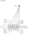
- Fig. 3A shows an example of a sensor.
- the sensor includes three phototransmitter (transmitter) elements 3 (elements EA to EC) and three photodetector (receiver) elements 4 (elements Ea to Ec) that are paired, respectively, so as to form three pairs.
- a light transmission area (transmission area) TA having six division areas is formed by the three phototransmitter elements 3, a lens body 5, and a phototransmitter-side prism 7.
- a light reception area (reception area) RA having six division areas is formed by the three photodetector elements 4, a lens body 6, and a photodetector-side prism 8.
- the light transmission area TA and the light reception area RA are overlaid or overlapped on each other to form a detection area AA.
- the prisms 7 and 8 each have, for example, a plurality of triangular portions each having two prism surfaces.
- a detection ray from an element EA of the phototransmitter element 3 is diffused by the two prism surfaces of the prism 7 in two directions, to form an area A of a division area TA11 and an area A' of a division area TA14 of the light transmission area TA, and detection rays are received by an element Ea of the photodetector element 4 via the two prism surfaces of the prism 8 from two directions, that is, from an area a of a division area RA11 and an area a' of a division area RA14 of the light reception area RA.
- a division area A1 of a first row or line is formed by the light transmission area TA11 and the light reception area RA11
- a division area A2 of a second row or line is formed by the light transmission area TA12 and the light reception area RA12.
- division areas A1 to A6 in which the light transmission areas TA11 to TA16 and the light reception areas RA11 to RA16 of six lines are overlaid or overlapped on each other in the longitudinal direction, are aligned from a position close to a sensor 100 toward a position distant from the sensor 110, to form the detection area AA.
- a plurality of division areas are formed in the lateral direction for each of the six rows or lines of the division areas A1 to A6, which lateral division areas are not shown.
- Fig. 6A illustrates an example of a conventional sensor.
- areas of two prism surfaces of a prism P are set such that a ratio between an area of a prism surface Pb by which a ray is applied to a rear portion corresponding to a short distance portion (closer to the sensor), and an area of a prism surface Pa by which a ray is applied to a front portion corresponding to a long distance portion (farther from the sensor) is 50:50 on each of the phototransmitter side and the photodetector side respectively. Therefore, as shown in Fig. 6B and Fig.
- the division areas RA11 and RA16, on the photodetector side, which are positioned at a position close to the sensor 110 having the prism P and a position distant from the sensor 110 having the prism P, respectively, are formed by prism surfaces having the same area
- the division areas TA11 and TA16, on the phototransmitter side, which are positioned at a position close to the sensor 110 having the prism P and a position distant from the sensor 110 having the prism P, respectively, are formed by prism surfaces having the same area.
- this sensor When this sensor is used as an automatic door sensor, the longer a distance between the sensor and a division area of the detection area is, that is, the farther the division area of the detection area is from the automatic door toward the external region, the lower the detection sensitivity is likely to become. Therefore, in a case where a door is to be immediately opened for a person approaching the automatic door from the external region, a detection sensitivity for the distant division area is low and detection becomes difficult, to reduce a response speed. In this case, it can be considered that a detection sensitivity is enhanced. However, enhancement of detection sensitivity leads to increase of an influence of a noise, and an S/N ratio cannot be improved, to make improvement of detection performance difficult.
- the present invention has been made to solve the above problems and has an object to provide an active object detection sensor that is capable of improving detection performance even in a detection area that is distant from a sensor, to advantageously obtain balance in sensitivity and an S/N ratio over the entirety of the detection area with ease.
- an active object detection sensor of the present invention operates to form a detection area by a transmission area and a reception area each having a plurality of division areas, and detect an object in the detection area.
- the active object detection sensor includes: a plurality of transmitter elements each configured to transmit a detection ray for object detection, to the transmission area; a plurality of receiver elements each configured to receive the detection ray reflected by the object in the reception area; and a transmission-side optical divider and a reception-side optical divider, disposed in front of the transmitter elements and the receiver elements, respectively, wherein each optical divider includes a plurality of optical dividing pieces having a plurality of optical deflection surfaces on which an angle of traveling direction of the detection ray is varied to a plurality of angles so as to correspond to the plurality of the division areas.
- each of the optical dividing pieces has a first optical deflection surface and a second optical deflection surface.
- a ratio of an area of the second optical deflection surface forming a division area that is closer to the sensor, relative to an area of the first optical deflection surface forming a division area that is farther from the sensor, is set so as to be different between a transmission side and a reception side.
- the phototransmitter-side optical divider varies an angle of a traveling direction of a detection ray, to a plurality of angles, for dividing toward the plurality of division areas, and the photodetector-side optical divider varies each traveling direction angle of the plurality of detection rays mentioned above, to equal in order to collect the detection rays from the plurality of division areas.
- the ratio of the area of the second optical deflection surface that forms the division area that is closer to the sensor, relative to the area of the first optical deflection surface that forms the division area that is farther from the sensor is set so as to be different between the transmission side and the reception side.
- a transmission power on the transmission side and a detection sensitivity on the reception side can be adjusted in a given manner. Therefore, a predetermined detection sensitivity for the division area can be set according to a mounting environment without adjusting a transmission power of the transmitter itself. Even in the division area that is farther from the sensor, an S/N ratio can be enhanced and an object detection performance can be improved, and a balance in sensitivity and an S/N ratio can be advantageously adjusted over the entirety of the detection area with ease.
- the ratio of the area of the second optical deflection surface to the area of the first optical deflection surface is set such that the area of the first optical deflection surface that forms a division area that is farther from the sensor is greater than the area of the second optical deflection surface that forms a division area that is closer to the sensor.
- the ratio of the area of the second optical deflection surface to the area of the first optical deflection surface is set such that the area of the first optical deflection surface is less than the area of the second optical deflection surface.
- the ratio of the area of the second optical deflection surface to the area of the first optical deflection surface on the reception side is set so as to be greater than the ratio of the area of the second optical deflection surface to the area of the first optical deflection surface on the transmission side.
- an area of the first optical deflection surface that forms the division area that is farther from the sensor on the transmission side is made greater than an area of the second optical deflection surface that forms the division area that is closer to the sensor on the transmission side, and thus a transmission power can be increased in the division area.
- An area of the first optical deflection surface is made less than an area of the second optical deflection surface on the reception side, and thus a detection sensitivity can be reduced to reduce an influence of ambient light.
- the ratio of the area of the second optical deflection surface to the area of the first optical deflection surface on the reception side is set so as to be greater than the ratio of the area of the second optical deflection surface to the area of the first optical deflection surface on the transmission side. Therefore, object detection performance for the division area that is farther from the sensor can be improved with ease. Thus, a balance in detection sensitivity and an S/N ratio can be advantageously adjusted over the entirety of the detection area.
- the ratio of the area of the second optical deflection surface to the area of the first optical deflection surface on the transmission side, and the ratio of the area of the second optical deflection surface to the area of the first optical deflection surface on the reception side are set so as to get close to each ratio in opposite directions, respectively, in magnitude relationship.
- a ratio of the area of the second optical deflection surface to the area of the first optical deflection surface is set so as to be less than 1 on the transmission side, and is set so as to be greater than 1 on the reception side. In this case, a balance in detection sensitivity and an S/N ratio can be more advantageously adjusted over the entirety of the detection area.
- each of the optical divider is a prism having a plurality of prism surface that varies an angle of traveling direction of the detection ray, to a plurality of angles. Therefore, the division areas can be easily formed.
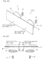
- Fig. 1 illustrates a detection area AA, as viewed from a sliding direction of an automatic door 60, in the case of an active object detection sensor 100 for use in an automatic door being used for starting an opening/closing controller of the automatic door, according to one embodiment of the present invention.
- the active object detection sensor 100 is provided in a transom 50, and the detection area AA is formed by six lines of division areas A1 to A6 in the longitudinal direction, from a position close to the sensor 100 toward a position distant from the sensor 100.
- an object such as a human body H is detected.
- a plurality of division areas are formed also in the lateral direction for each of the division areas A1 to A6 of the six lines, which lateral division areas are not shown. The plurality of areas in the lateral direction may not be formed.
- the active object detection sensor 100 is, for example, an AIR (Active InfraRed detection) sensor, and includes: a phototransmitter (transmitter) 1 that transmits near infrared ray, as one kind of detection rays for object detection, toward the detection area AA described above; and a photodetector (receiver) 2 that receives detection ray reflected by an object to generate a light reception signal.
- Fig. 2B is a plan view of the sensor shown in Fig. 2A as viewed from above the sensor.
- the phototransmitter 1 includes: for example, three transmitter elements (hereinafter, also referred to as phototransmitter elements) 3 including infrared emitting diodes for transmitting near infrared rays as detection rays; a lens body 5 disposed in front of the phototransmitter elements 3; and a phototransmitter-side optical divider 7, such as a prism, disposed in front of the lens body 5.
- phototransmitter elements including infrared emitting diodes for transmitting near infrared rays as detection rays
- a lens body 5 disposed in front of the phototransmitter elements 3
- a phototransmitter-side optical divider 7, such as a prism disposed in front of the lens body 5.
- the photodetector 2 includes: three receiver elements (hereinafter, also referred to as photodetector elements) 4; a lens body 6, disposed in front of the photodetector elements 4, for collecting near infrared rays reflected from the detection area AA such that the reflected near infrared rays are incident on each photodetector element 4; and a photodetector-side optical divider 8, such as a prism, disposed in front of the lens body 6.
- the optical divider 7 and the optical divider 8 are integrated with each other. However, the optical divider 7 and the optical divider 8 may be separately provided.
- the lens bodies 5 and 6 operate to define or constrain the detection area AA.
- Each of the optical dividers 7 and 8 has peaks and troughs extending in a lateral or horizontal direction.
- a light transmission area TA having six division areas TA11 to TA16 is formed by the three phototransmitter elements 3, the lens body 5, and the phototransmitter-side prism 7.
- a light reception area RA having six division areas RA11 to RA16 is formed by the three photodetector elements 4, the lens body 6, and the photodetector-side prism 8.
- the light transmission area TA and the light reception area RA each having six division areas are overlaid or overlapped on each other, to form the detection area AA having the division areas A1 to A6.
- a division area A1 of a first row or line is formed by RA11 and TA11, and division areas are similarly formed up to a division area A6 of a sixth row or line formed by RA16 and TA16.
- Fig. 4A and Fig. 4B are a cross-sectional view taken along a line IVA-IVA in Fig. 2B , and a cross-sectional view taken along a line IVB-IVB in Fig. 2B , respectively.
- the phototransmitter-side prism 7 has a plurality of optical dividing pieces (prism pieces) 7S having first and second optical deflection surfaces (prism surfaces) 7a, 7b that vary an angle of a traveling direction of a detection ray, to a plurality of angles, for example, two angles, for dividing toward the plurality of division areas, and the plurality of optical dividing pieces 7S are integrally formed.
- the first optical deflection surface 7a forms a division area that is farther from the sensor 100 (forms a front portion of the detection area).
- the second optical deflection surface 7b forms a division area that is closer to the sensor 100 (forms a rear portion of the detection area).
- an area of the first optical deflection surface 7a that forms a division area that is farther from the sensor 100 (in the light transmission area TA) is set so as to be greater than an area of the second optical deflection surface 7b that forms a division area that is closer to the sensor 100 (in the light transmission area TA). That is, on the phototransmitter side, a ratio of an area of the second optical deflection surface 7b to an area of the first optical deflection surface 7a is set so as to be less than 1.
- the photodetector-side prism 8 has a plurality of optical dividing pieces (prism pieces) 8S having first and second optical deflection surfaces (prism surfaces) 8a, 8b that vary each angle of traveling directions (such as angles of incidence) of two aforementioned detection rays, to a single identical angle (such as a refracted output angle) so as to collect the detection rays from the plurality of division areas, and the plurality of optical dividing pieces 8S are integrally formed.
- the first optical deflection surface 8a forms a division area that is farther from the sensor 100 (forms a front portion of the detection area).
- the second optical deflection surface 8b forms a division area that is closer to the sensor 100 (forms a rear portion of the detection area).
- an area of the first optical deflection surface 8a that forms a division area that is farther from the sensor 100 (in the light transmission area RA) is set so as to be less than an area of the second optical deflection surface 8b that forms a division area that is closer to the sensor 100 (in the light transmission area RA). That is, on the photodetector side, a ratio of an area of the second optical deflection surface 8b to an area of the first optical deflection surface 8a is set so as to be greater than 1.
- an angle of a traveling direction (such as the angle of incidence for the prism 7) of the detection ray is changed based on an angle of a given optical deflection surface, to enable the detection ray to be varied and assigned to any given division area.
- a ratio of an area of the second optical deflection surface that forms the division area that is closer to the sensor, relative to an area of the first optical deflection surface that forms the division area that is farther from the sensor is set so as to be different between the transmission side and the reception side, and the ratio has a value different from 1 on both sides.
- an area of the first optical deflection surface 7a that forms the division area TA16 farthest from the sensor 100 (forms the forefront of the detection area) is set to 80 that is greater than 50 in conventional art ( Fig. 6C )
- an area of the second optical deflection surface 7b that forms the division area TA11 closest to the sensor 100 (forms the rearmost portion of the detection area) is set to 20 that is much less than 50 in conventional art ( Fig. 6C ).
- the ratio of the area of the second optical deflection surface 7b to the area of the first optical deflection surface 7a is set to 1/4 that is less than 1.
- an area of the first optical deflection surface 8a that forms the division area RA16 farthest from the sensor 100 (forms the forefront portion of the detection area) is set to 40 that is slightly less than 50 in conventional art ( Fig. 6B ), and an area of the second optical deflection surface 8b that forms the division area RA11 closest to the sensor 100 (forms the rearmost portion of the detection area) is set to 60 that is slightly greater than 50 in conventional art ( Fig. 6B ).
- the ratio of the area of the second optical deflection surface 8b to the area of the first optical deflection surface 8a is set to 1.5 that is greater than 1.
- the ratio of area on the transmission side and the ratio of area on the reception side are set so as to get close to each ratio in opposite directions, respectively, in magnitude relationship. Further, the ratio of area has a value different from 1 on each of the transmission side and the reception side.
- each detection sensitivity for the division areas A1 to A6 of the detection area AA are in proportion to values obtained by multiplying values of the areas of the optical deflection surfaces for the division areas TA11 to TA16 of the light transmission area TA, by values of the areas of the optical deflection surfaces for the division areas RA11 to RA16 of the light reception area RA, respectively, since the detection area AA is formed by the division areas TA11 to TA16 of the light transmission area TA and the division areas RA11 to RA16 of the light reception area RA.
- a detection sensitivity of the division area A1 that is closest to the sensor 100 is in proportion to a value obtained by multiplying the value, 20, of the area of the second optical deflection surface 7b that forms the division area TA11 of the light transmission area TA, by the value, 60, of the area of the second optical deflection surface 8b that forms the division area RA11 of the light reception area RA. Therefore, the detection sensitivity of the division area A1 represents a value, 1200, that is less than 2500 in conventional art.
- a detection sensitivity of the division area that is farther from the sensor 100 is increased as compared to a detection sensitivity of conventional art, and a detection sensitivity of the division area that is closer to the sensor 100 is reduced as compared to a detection sensitivity of conventional art.
- an amount of noise in the division area A6 that is farthest from the sensor 100 is in proportion to a value, 40, of an area of the first optical deflection surface 8a that forms the division area RA16 of the light reception area RA, and the amount of noise represents a value, 40, that is less than 50 in conventional art.
- an amount of noise in the division area A1 that is closest to the sensor 100 is in proportion to a value, 60, of an area of the second optical deflection surface 8b that forms the division area RA11 of the light reception area RA, and the amount of noise represents a value, 60, that is higher than 50 in conventional art.
- an influence of a noise in the division area that is farther from the sensor 100 is reduced as compared to conventional art, and an influence of a noise in the division area that is closer to the sensor 100 is increased as compared to conventional art.
- a ratio between an S/N ratio for the division area A6 that is farther from the sensor 100 and an S/N ratio for the division area A1 that is close to the sensor 100 is compared between the present embodiment and a conventional art, and the results are as follows.
- a balance in the present embodiment is reduced or is worse than the conventional art since the S/N ratio is different depending on whether the division area is closer to the sensor 100 or farther from the sensor 100.
- the balance is not reduced.
- the same object enters the division area A6 and the division area A1 in general, and a signal value detected in the division area A1 is greater than a signal value detected in the division area A6 even for the same object since the division area A1 is closer to the sensor 100 than the division area A6 is. If the signal value of the division area A1 is four times greater than the signal value of the division area A6, the balance based on the above ratio is very advantageous.
- an influence of a nose in the division area that is closer to the sensor can be also considered while object detection performance for the division area that is farther from the sensor can be improved.
- a ratio of an area of the second optical deflection surface 7b to an area of the first optical deflection surface 7a on the phototransmitter side is set so as to be less than a ratio of an area of the second optical deflection surface 8b to an area of the first optical deflection surface 8a on the photodetector side. Further, a ratio of an area of the second optical deflection surface 7b to an area of the first optical deflection surface 7a on the phototransmitter side and a ratio of an area of the second optical deflection surface 8b to an area of the first optical deflection surface 8a on the photodetector side are set so as to get close to each ratio in opposite directions, respectively, in magnitude relationship.
- a ratio of an area of the second optical deflection surface to an area of the first optical deflection surface is set so as to be less than 1 on the phototransmitter side, and is set so as to be greater than 1 on the photodetector side. In this case, a balance in sensitivity and an S/N ratio can be advantageously adjusted over the entirety of the detection area.
- the automatic door apparatus shown in Fig. 1 determines whether or not a light reception signal that is individually inputted from the photodetector elements 4 for each line has a level that exceeds a setting level.
- the automatic door apparatus determines that the light reception signal has a level that exceeds the setting level, it outputs an object detection signal to a not-illustrated opening/closing controller of the automatic door 60. According to the object detection signal, the automatic door 60 is opened or closed.
- the ratio of the area of the second optical deflection surface that forms the division area that is closer to the sensor, relative to the area of the first optical deflection surface that forms the division area that is farther from the sensor is set so as to be different between the transmission side and the reception side.
- a transmission power on the phototransmitter (transmission) side and a detection sensitivity on the photodetector (reception) side can be adjusted in a given manner. Therefore, a predetermined detection sensitivity for the division area can be set according to a mounting environment without adjusting a transmission power of the transmitter itself. Even in the division area that is farther from the sensor, an object detection performance can be improved, and a balance in sensitivity and an S/N ratio can be advantageously adjusted over the entirety of the detection area with ease.
- a main axis, such as an optical axis, of the lens body on the phototransmitter side is adjusted to the phototransmitter element that forms the division area that is farther from the sensor, and a main axis, such as an optical axis, of the lens body on the photodetector side is adjusted to the photodetector element that forms the division area that is closer to the sensor, to enable adjustment of an S/N ratio.
- a division area that is formed by a detection ray of an element deviated from the main axis is likely to be unfocused.
- the S/N ratio can be adjusted.
- different size lenses are necessary, which causes increase in cost.
- near infrared rays are used as detection rays.
- detection rays are not limited to near infrared rays.
- visible light, infrared rays, microwaves, or laser light may be used.
- a prism is used as an optical divider.
- the optical divider is not limited to a prism.
- a mirror having a plurality of optical deflection surfaces may be used.
- an optical divider for division into three or more may be used instead of the aforementioned optical divider for division into two.
Landscapes
- Physics & Mathematics (AREA)
- Engineering & Computer Science (AREA)
- General Physics & Mathematics (AREA)
- Computer Networks & Wireless Communication (AREA)
- Radar, Positioning & Navigation (AREA)
- Remote Sensing (AREA)
- Electromagnetism (AREA)
- Spectroscopy & Molecular Physics (AREA)
- Geophysics And Detection Of Objects (AREA)
- Power-Operated Mechanisms For Wings (AREA)
- Optical Radar Systems And Details Thereof (AREA)
Description
- The present invention relates to an active object detection sensor that transmits detection rays for object detection toward a detection area, and detects an object based on a reception signal generated when receiving detection rays reflected by the object.
- To date, an active object detection sensor has been known which transmits detection rays, such as infrared rays or near infrared rays, for object detection, from a transmitter toward a detection area, causes a receiver to receive detection rays reflected by an object and to generate a reception signal, and detects an object such as a human body when the reception signal is determined as having a level that exceeds a setting level.
- As an example of the active object detection sensor, the use is made of a sensor that forms a detection area divided into a plurality of division areas, to arrange plural columns of the division areas in the lateral direction, and arrange plural rows of the division areas in the longitudinal direction from a position close to the sensor toward a position distant from the sensor (for example, Japanese Laid-Open Patent Publication No.
2009-115792 JP 2013-72863 JP 2009-122044 -
Fig. 3A shows an example of a sensor. The sensor includes three phototransmitter (transmitter) elements 3 (elements EA to EC) and three photodetector (receiver) elements 4 (elements Ea to Ec) that are paired, respectively, so as to form three pairs. On the phototransmitter (transmission) side, a light transmission area (transmission area) TA having six division areas is formed by the threephototransmitter elements 3, alens body 5, and a phototransmitter-side prism 7. On the photodetector (reception) side, a light reception area (reception area) RA having six division areas is formed by the threephotodetector elements 4, alens body 6, and a photodetector-side prism 8. The light transmission area TA and the light reception area RA are overlaid or overlapped on each other to form a detection area AA. Theprisms - For example, a detection ray from an element EA of the
phototransmitter element 3 is diffused by the two prism surfaces of theprism 7 in two directions, to form an area A of a division area TA11 and an area A' of a division area TA14 of the light transmission area TA, and detection rays are received by an element Ea of thephotodetector element 4 via the two prism surfaces of theprism 8 from two directions, that is, from an area a of a division area RA11 and an area a' of a division area RA14 of the light reception area RA. A division area A1 of a first row or line is formed by the light transmission area TA11 and the light reception area RA11, and a division area A2 of a second row or line is formed by the light transmission area TA12 and the light reception area RA12. As shown inFig. 3B , division areas A1 to A6 in which the light transmission areas TA11 to TA16 and the light reception areas RA11 to RA16 of six lines are overlaid or overlapped on each other in the longitudinal direction, are aligned from a position close to asensor 100 toward a position distant from thesensor 110, to form the detection area AA. It is to be noted that a plurality of division areas are formed in the lateral direction for each of the six rows or lines of the division areas A1 to A6, which lateral division areas are not shown. -
Fig. 6A illustrates an example of a conventional sensor. In general, areas of two prism surfaces of a prism P are set such that a ratio between an area of a prism surface Pb by which a ray is applied to a rear portion corresponding to a short distance portion (closer to the sensor), and an area of a prism surface Pa by which a ray is applied to a front portion corresponding to a long distance portion (farther from the sensor) is 50:50 on each of the phototransmitter side and the photodetector side respectively. Therefore, as shown inFig. 6B and Fig. 6C , the division areas RA11 and RA16, on the photodetector side, which are positioned at a position close to thesensor 110 having the prism P and a position distant from thesensor 110 having the prism P, respectively, are formed by prism surfaces having the same area, and the division areas TA11 and TA16, on the phototransmitter side, which are positioned at a position close to thesensor 110 having the prism P and a position distant from thesensor 110 having the prism P, respectively, are formed by prism surfaces having the same area. - When this sensor is used as an automatic door sensor, the longer a distance between the sensor and a division area of the detection area is, that is, the farther the division area of the detection area is from the automatic door toward the external region, the lower the detection sensitivity is likely to become. Therefore, in a case where a door is to be immediately opened for a person approaching the automatic door from the external region, a detection sensitivity for the distant division area is low and detection becomes difficult, to reduce a response speed. In this case, it can be considered that a detection sensitivity is enhanced. However, enhancement of detection sensitivity leads to increase of an influence of a noise, and an S/N ratio cannot be improved, to make improvement of detection performance difficult.
- On the one hand, in a division area close to the automatic door, detection sensitivity is unnecessarily enhanced due to a short distance from the sensor, so that malfunction is likely to occur. Thus, in the case as described above, in the distant division area, detection performance cannot be improved, whereas, in the close division area, detection sensitivity is unnecessarily enhanced to increase the number of times of malfunction, and the sensor is impractical.
- On the other hand, it is known that, in order to make the detection sensitivity uniform over the entirety of the detection area, an angle of the prism surface is varied (for example, Japanese Laid-Open Patent Publication No.
2004-170128 - The present invention has been made to solve the above problems and has an object to provide an active object detection sensor that is capable of improving detection performance even in a detection area that is distant from a sensor, to advantageously obtain balance in sensitivity and an S/N ratio over the entirety of the detection area with ease.
- In order to attain the aforementioned object, an active object detection sensor of the present invention operates to form a detection area by a transmission area and a reception area each having a plurality of division areas, and detect an object in the detection area. The active object detection sensor includes: a plurality of transmitter elements each configured to transmit a detection ray for object detection, to the transmission area; a plurality of receiver elements each configured to receive the detection ray reflected by the object in the reception area; and a transmission-side optical divider and a reception-side optical divider, disposed in front of the transmitter elements and the receiver elements, respectively, wherein each optical divider includes a plurality of optical dividing pieces having a plurality of optical deflection surfaces on which an angle of traveling direction of the detection ray is varied to a plurality of angles so as to correspond to the plurality of the division areas. And each of the optical dividing pieces has a first optical deflection surface and a second optical deflection surface. In the optical dividers, a ratio of an area of the second optical deflection surface forming a division area that is closer to the sensor, relative to an area of the first optical deflection surface forming a division area that is farther from the sensor, is set so as to be different between a transmission side and a reception side.
- With the plurality of optical deflection surfaces mentioned above on which a traveling direction angle of the detection ray is varied to a plurality of angles so as to correspond to the plurality of division areas, the phototransmitter-side optical divider varies an angle of a traveling direction of a detection ray, to a plurality of angles, for dividing toward the plurality of division areas, and the photodetector-side optical divider varies each traveling direction angle of the plurality of detection rays mentioned above, to equal in order to collect the detection rays from the plurality of division areas. So, in this configuration, the ratio of the area of the second optical deflection surface that forms the division area that is closer to the sensor, relative to the area of the first optical deflection surface that forms the division area that is farther from the sensor is set so as to be different between the transmission side and the reception side. Thus, by selecting the ratio of area, in each the division area, a transmission power on the transmission side and a detection sensitivity on the reception side can be adjusted in a given manner. Therefore, a predetermined detection sensitivity for the division area can be set according to a mounting environment without adjusting a transmission power of the transmitter itself. Even in the division area that is farther from the sensor, an S/N ratio can be enhanced and an object detection performance can be improved, and a balance in sensitivity and an S/N ratio can be advantageously adjusted over the entirety of the detection area with ease.
- Preferably, on the transmission side, the ratio of the area of the second optical deflection surface to the area of the first optical deflection surface is set such that the area of the first optical deflection surface that forms a division area that is farther from the sensor is greater than the area of the second optical deflection surface that forms a division area that is closer to the sensor. Preferably, on the reception side, the ratio of the area of the second optical deflection surface to the area of the first optical deflection surface is set such that the area of the first optical deflection surface is less than the area of the second optical deflection surface. Then, the ratio of the area of the second optical deflection surface to the area of the first optical deflection surface on the reception side is set so as to be greater than the ratio of the area of the second optical deflection surface to the area of the first optical deflection surface on the transmission side.
- In this case, an area of the first optical deflection surface that forms the division area that is farther from the sensor on the transmission side is made greater than an area of the second optical deflection surface that forms the division area that is closer to the sensor on the transmission side, and thus a transmission power can be increased in the division area. An area of the first optical deflection surface is made less than an area of the second optical deflection surface on the reception side, and thus a detection sensitivity can be reduced to reduce an influence of ambient light. Further, the ratio of the area of the second optical deflection surface to the area of the first optical deflection surface on the reception side is set so as to be greater than the ratio of the area of the second optical deflection surface to the area of the first optical deflection surface on the transmission side. Therefore, object detection performance for the division area that is farther from the sensor can be improved with ease. Thus, a balance in detection sensitivity and an S/N ratio can be advantageously adjusted over the entirety of the detection area.
- Preferably, the ratio of the area of the second optical deflection surface to the area of the first optical deflection surface on the transmission side, and the ratio of the area of the second optical deflection surface to the area of the first optical deflection surface on the reception side are set so as to get close to each ratio in opposite directions, respectively, in magnitude relationship. Further, preferably, a ratio of the area of the second optical deflection surface to the area of the first optical deflection surface is set so as to be less than 1 on the transmission side, and is set so as to be greater than 1 on the reception side. In this case, a balance in detection sensitivity and an S/N ratio can be more advantageously adjusted over the entirety of the detection area.
- Preferably, each of the optical divider is a prism having a plurality of prism surface that varies an angle of traveling direction of the detection ray, to a plurality of angles. Therefore, the division areas can be easily formed.
- Any combination of at least two constructions, disclosed in the appended claims and/or the specification and/or the accompanying drawings should be construed as included within the scope of the present invention. In particular, any combination of two or more of the appended claims should be equally construed as included within the scope of the present invention.
- In any event, the present invention will become more clearly understood from the following description of preferred embodiments thereof, when taken in conjunction with the accompanying drawings. However, the embodiments and the drawings are given only for the purpose of illustration and explanation, and are not to be taken as limiting the scope of the present invention in any way whatsoever, which scope is to be determined by the appended claims. In the accompanying drawings, like reference numerals are used to denote like parts throughout the several views, and:
-
Fig. 1 illustrates a detection area as viewed from a sliding direction of an automatic door using an active object detection sensor for use in the automatic door according to one embodiment of the present invention; -
Fig. 2A is a schematic perspective view of the active object detection sensor; -
Fig. 2B is a plan view of the active object detection sensor; -
Fig. 3A is a schematic diagram illustrating a detection area in which a light transmission area by a phototransmitter element and a light reception area by a photodetector element are overlaid or overlapped on each other; -
Fig. 3B is a side view of the detection area in which the light transmission area and the light reception areas are overlaid or overlapped on each other; -
Fig. 4A is an enlarged cross-sectional view, taken along a line IVA-IVA inFig. 2B , illustrating a prism on a photodetector side; -
Fig. 4B is an enlarged cross-sectional view, taken along a line IVB-IVB inFig. 2B , illustrating a prism on a phototransmitter side; -
Fig. 5A is a side view of a light reception area on a photodetector side according to one example; -
Fig. 5B is a side view of a light transmission area on a phototransmitter side according to one example; -
Fig. 6A is an enlarged cross-sectional view of a conventional prism; -
Fig. 6B is a side view of a light reception area on a photodetector side; and -
Fig. 6C is a side view of a light transmission area on a phototransmitter side. - Hereinafter, one embodiment of the present invention will be described with reference to the drawings.
Fig. 1 illustrates a detection area AA, as viewed from a sliding direction of anautomatic door 60, in the case of an activeobject detection sensor 100 for use in an automatic door being used for starting an opening/closing controller of the automatic door, according to one embodiment of the present invention. As shown inFIG. 1 , the activeobject detection sensor 100 is provided in atransom 50, and the detection area AA is formed by six lines of division areas A1 to A6 in the longitudinal direction, from a position close to thesensor 100 toward a position distant from thesensor 100. In the detection area AA, an object such as a human body H is detected. It is to be noted that a plurality of division areas are formed also in the lateral direction for each of the division areas A1 to A6 of the six lines, which lateral division areas are not shown. The plurality of areas in the lateral direction may not be formed. - As shown in
Fig. 2A , the activeobject detection sensor 100 is, for example, an AIR (Active InfraRed detection) sensor, and includes: a phototransmitter (transmitter) 1 that transmits near infrared ray, as one kind of detection rays for object detection, toward the detection area AA described above; and a photodetector (receiver) 2 that receives detection ray reflected by an object to generate a light reception signal.Fig. 2B is a plan view of the sensor shown inFig. 2A as viewed from above the sensor. - The phototransmitter 1 includes: for example, three transmitter elements (hereinafter, also referred to as phototransmitter elements) 3 including infrared emitting diodes for transmitting near infrared rays as detection rays; a
lens body 5 disposed in front of thephototransmitter elements 3; and a phototransmitter-sideoptical divider 7, such as a prism, disposed in front of thelens body 5. Thephotodetector 2 includes: three receiver elements (hereinafter, also referred to as photodetector elements) 4; alens body 6, disposed in front of thephotodetector elements 4, for collecting near infrared rays reflected from the detection area AA such that the reflected near infrared rays are incident on eachphotodetector element 4; and a photodetector-sideoptical divider 8, such as a prism, disposed in front of thelens body 6. InFig. 2 , theoptical divider 7 and theoptical divider 8 are integrated with each other. However, theoptical divider 7 and theoptical divider 8 may be separately provided. Thelens bodies optical dividers - As shown in
Fig. 3A , on the phototransmitter (transmission) side, a light transmission area TA having six division areas TA11 to TA16 is formed by the threephototransmitter elements 3, thelens body 5, and the phototransmitter-side prism 7. On the photodetector (reception) side, a light reception area RA having six division areas RA11 to RA16 is formed by the threephotodetector elements 4, thelens body 6, and the photodetector-side prism 8. The light transmission area TA and the light reception area RA each having six division areas are overlaid or overlapped on each other, to form the detection area AA having the division areas A1 to A6. As shown inFig. 3B , for example, a division area A1 of a first row or line is formed by RA11 and TA11, and division areas are similarly formed up to a division area A6 of a sixth row or line formed by RA16 and TA16. -
Fig. 4A and Fig. 4B are a cross-sectional view taken along a line IVA-IVA inFig. 2B , and a cross-sectional view taken along a line IVB-IVB inFig. 2B , respectively. As shown inFig. 4B , the phototransmitter-side prism 7 has a plurality of optical dividing pieces (prism pieces) 7S having first and second optical deflection surfaces (prism surfaces) 7a, 7b that vary an angle of a traveling direction of a detection ray, to a plurality of angles, for example, two angles, for dividing toward the plurality of division areas, and the plurality of optical dividing pieces 7S are integrally formed. The first optical deflection surface 7a forms a division area that is farther from the sensor 100 (forms a front portion of the detection area). The secondoptical deflection surface 7b forms a division area that is closer to the sensor 100 (forms a rear portion of the detection area). In this example, an area of the first optical deflection surface 7a that forms a division area that is farther from the sensor 100 (in the light transmission area TA) is set so as to be greater than an area of the secondoptical deflection surface 7b that forms a division area that is closer to the sensor 100 (in the light transmission area TA). That is, on the phototransmitter side, a ratio of an area of the secondoptical deflection surface 7b to an area of the first optical deflection surface 7a is set so as to be less than 1. - As shown in
Fig. 4A , the photodetector-side prism 8 has a plurality of optical dividing pieces (prism pieces) 8S having first and second optical deflection surfaces (prism surfaces) 8a, 8b that vary each angle of traveling directions (such as angles of incidence) of two aforementioned detection rays, to a single identical angle (such as a refracted output angle) so as to collect the detection rays from the plurality of division areas, and the plurality ofoptical dividing pieces 8S are integrally formed. The firstoptical deflection surface 8a forms a division area that is farther from the sensor 100 (forms a front portion of the detection area). The secondoptical deflection surface 8b forms a division area that is closer to the sensor 100 (forms a rear portion of the detection area). In this example, an area of the firstoptical deflection surface 8a that forms a division area that is farther from the sensor 100 (in the light transmission area RA) is set so as to be less than an area of the secondoptical deflection surface 8b that forms a division area that is closer to the sensor 100 (in the light transmission area RA). That is, on the photodetector side, a ratio of an area of the secondoptical deflection surface 8b to an area of the firstoptical deflection surface 8a is set so as to be greater than 1. It is to be noted that, on at least one of the phototransmitter side detection ray and the photodetector side detection ray, an angle of a traveling direction (such as the angle of incidence for the prism 7) of the detection ray is changed based on an angle of a given optical deflection surface, to enable the detection ray to be varied and assigned to any given division area. - Thus, in the plural optical deflection surfaces of the
respective prism pieces 7S, 8S, a ratio of an area of the second optical deflection surface that forms the division area that is closer to the sensor, relative to an area of the first optical deflection surface that forms the division area that is farther from the sensor is set so as to be different between the transmission side and the reception side, and the ratio has a value different from 1 on both sides. - For example, as indicated in one example shown in
Fig. 5B , in the light transmission area TA, an area of the first optical deflection surface 7a that forms the division area TA16 farthest from the sensor 100 (forms the forefront of the detection area) is set to 80 that is greater than 50 in conventional art (Fig. 6C ), and an area of the secondoptical deflection surface 7b that forms the division area TA11 closest to the sensor 100 (forms the rearmost portion of the detection area) is set to 20 that is much less than 50 in conventional art (Fig. 6C ). Thus, the ratio of the area of the secondoptical deflection surface 7b to the area of the first optical deflection surface 7a is set to 1/4 that is less than 1. - As shown in
Fig. 5A , in the photodetector side, an area of the firstoptical deflection surface 8a that forms the division area RA16 farthest from the sensor 100 (forms the forefront portion of the detection area) is set to 40 that is slightly less than 50 in conventional art (Fig. 6B ), and an area of the secondoptical deflection surface 8b that forms the division area RA11 closest to the sensor 100 (forms the rearmost portion of the detection area) is set to 60 that is slightly greater than 50 in conventional art (Fig. 6B ). Thus, the ratio of the area of the secondoptical deflection surface 8b to the area of the firstoptical deflection surface 8a is set to 1.5 that is greater than 1. As above, the ratio of area on the transmission side and the ratio of area on the reception side are set so as to get close to each ratio in opposite directions, respectively, in magnitude relationship. Further, the ratio of area has a value different from 1 on each of the transmission side and the reception side. - When a light transmission power of the phototransmitter 1 itself is constant, each detection sensitivity for the division areas A1 to A6 of the detection area AA are in proportion to values obtained by multiplying values of the areas of the optical deflection surfaces for the division areas TA11 to TA16 of the light transmission area TA, by values of the areas of the optical deflection surfaces for the division areas RA11 to RA16 of the light reception area RA, respectively, since the detection area AA is formed by the division areas TA11 to TA16 of the light transmission area TA and the division areas RA11 to RA16 of the light reception area RA.
- For example, a detection sensitivity of the division area A6 that is farthest from the
sensor 100 is in proportion to a value obtained by multiplying the value, 80, of the area of the first optical deflection surface 7a that forms the division area TA16 of the light transmission area TA, by the value, 40, of the area of the firstoptical deflection surface 8a that forms the division area RA16 of the light reception area RA. Therefore, the detection sensitivity of the division area A6 represents a value, 3200, that is higher than 2500 (=50×50) (Fig. 6B, Fig. 6C ) in conventional art. On the other hand, a detection sensitivity of the division area A1 that is closest to thesensor 100 is in proportion to a value obtained by multiplying the value, 20, of the area of the secondoptical deflection surface 7b that forms the division area TA11 of the light transmission area TA, by the value, 60, of the area of the secondoptical deflection surface 8b that forms the division area RA11 of the light reception area RA. Therefore, the detection sensitivity of the division area A1 represents a value, 1200, that is less than 2500 in conventional art. - That is, a detection sensitivity of the division area that is farther from the
sensor 100 is increased as compared to a detection sensitivity of conventional art, and a detection sensitivity of the division area that is closer to thesensor 100 is reduced as compared to a detection sensitivity of conventional art. - Further, an amount of noise in the division area A6 that is farthest from the
sensor 100 is in proportion to a value, 40, of an area of the firstoptical deflection surface 8a that forms the division area RA16 of the light reception area RA, and the amount of noise represents a value, 40, that is less than 50 in conventional art. On the other hand, an amount of noise in the division area A1 that is closest to thesensor 100 is in proportion to a value, 60, of an area of the secondoptical deflection surface 8b that forms the division area RA11 of the light reception area RA, and the amount of noise represents a value, 60, that is higher than 50 in conventional art. - That is, an influence of a noise in the division area that is farther from the
sensor 100 is reduced as compared to conventional art, and an influence of a noise in the division area that is closer to thesensor 100 is increased as compared to conventional art. - A ratio between an S/N ratio for the division area A6 that is farther from the
sensor 100 and an S/N ratio for the division area A1 that is close to thesensor 100 is compared between the present embodiment and a conventional art, and the results are as follows.
In a conventional art, S/N (A6):S/N (A1)=2500/50:2500/50=1:1
In the present embodiment, S/N (A6):S/N (A1)=3200/40:1200/60=4:1 - In this case, it appears that a balance in the present embodiment is reduced or is worse than the conventional art since the S/N ratio is different depending on whether the division area is closer to the
sensor 100 or farther from thesensor 100. However, the balance is not reduced. In practical use, the same object enters the division area A6 and the division area A1 in general, and a signal value detected in the division area A1 is greater than a signal value detected in the division area A6 even for the same object since the division area A1 is closer to thesensor 100 than the division area A6 is. If the signal value of the division area A1 is four times greater than the signal value of the division area A6, the balance based on the above ratio is very advantageous. - Thus, in the present embodiment, an influence of a nose in the division area that is closer to the sensor can be also considered while object detection performance for the division area that is farther from the sensor can be improved.
- Therefore, a ratio of an area of the second
optical deflection surface 7b to an area of the first optical deflection surface 7a on the phototransmitter side is set so as to be less than a ratio of an area of the secondoptical deflection surface 8b to an area of the firstoptical deflection surface 8a on the photodetector side. Further, a ratio of an area of the secondoptical deflection surface 7b to an area of the first optical deflection surface 7a on the phototransmitter side and a ratio of an area of the secondoptical deflection surface 8b to an area of the firstoptical deflection surface 8a on the photodetector side are set so as to get close to each ratio in opposite directions, respectively, in magnitude relationship. Further, a ratio of an area of the second optical deflection surface to an area of the first optical deflection surface is set so as to be less than 1 on the phototransmitter side, and is set so as to be greater than 1 on the photodetector side. In this case, a balance in sensitivity and an S/N ratio can be advantageously adjusted over the entirety of the detection area. - In the above configuration, the automatic door apparatus shown in
Fig. 1 determines whether or not a light reception signal that is individually inputted from thephotodetector elements 4 for each line has a level that exceeds a setting level. When the automatic door apparatus determines that the light reception signal has a level that exceeds the setting level, it outputs an object detection signal to a not-illustrated opening/closing controller of theautomatic door 60. According to the object detection signal, theautomatic door 60 is opened or closed. - Thus, in the present embodiment, the ratio of the area of the second optical deflection surface that forms the division area that is closer to the sensor, relative to the area of the first optical deflection surface that forms the division area that is farther from the sensor is set so as to be different between the transmission side and the reception side. Thus, by selecting the ratio of area, in each division area, a transmission power on the phototransmitter (transmission) side and a detection sensitivity on the photodetector (reception) side can be adjusted in a given manner. Therefore, a predetermined detection sensitivity for the division area can be set according to a mounting environment without adjusting a transmission power of the transmitter itself. Even in the division area that is farther from the sensor, an object detection performance can be improved, and a balance in sensitivity and an S/N ratio can be advantageously adjusted over the entirety of the detection area with ease.
- A main axis, such as an optical axis, of the lens body on the phototransmitter side is adjusted to the phototransmitter element that forms the division area that is farther from the sensor, and a main axis, such as an optical axis, of the lens body on the photodetector side is adjusted to the photodetector element that forms the division area that is closer to the sensor, to enable adjustment of an S/N ratio. However, a division area that is formed by a detection ray of an element deviated from the main axis is likely to be unfocused. Further, by the size of the lens body on the phototransmitter side being increased and by the size of the lens body on the photodetector side being reduced, the S/N ratio can be adjusted. However, different size lenses are necessary, which causes increase in cost.
- In each embodiment, near infrared rays are used as detection rays. However, detection rays are not limited to near infrared rays. For example, visible light, infrared rays, microwaves, or laser light may be used.
- In each embodiment, a prism is used as an optical divider. However, the optical divider is not limited to a prism. For example, a mirror having a plurality of optical deflection surfaces (mirror surfaces) may be used. Further, an optical divider for division into three or more may be used instead of the aforementioned optical divider for division into two.
-
- 1 ···
- phototransmitter (transmitter)
- 2 ···
- photodetector (receiver)
- 3 ···
- phototransmitter (transmitter) element
- 4 ···
- photodetector (receiver) element
- 5, 6 ···
- lens body
- 7 ···
- phototransmitter-side optical divider (prism)
- 7S ···
- optical dividing piece (prism piece)
- 7a ···
- first optical deflection surface (prism surface)
- 7b ···
- second optical deflection surface (prism surface)
- 8 ···
- photodetector-side optical divider (prism)
- 8S ···
- optical dividing piece (prism piece)
- 8a ···
- first optical deflection surface (prism surface)
- 8b ···
- second optical deflection surface (prism surface)
- 60 ···
- automatic door
- 100 ···
- active object detection sensor
- AA ···
- detection area
- A1 to A6 ···
- division area
- TA ···
- light transmission area (transmission area)
- TA11 to TA16 ···
- division area
- RA ···
- light reception area (reception area)
- RA11 to RA16 ···
- division area
Claims (5)
- An active object detection sensor (100) that operates to form a detection area (AA) by a transmission area (TA) and a reception area (RA) each having a plurality of division areas (A1 to A6, TA11 to TA16, RA11 to RA16), and detect an object in the detection area (AA), the active object detection sensor (100) comprising:a plurality of transmitter elements (3) each configured to transmit a detection ray for object detection, to the transmission area (TA);a plurality of receiver elements (4) each configured to receive the detection ray reflected by the object in the reception area (RA); anda transmission-side optical divider (7) and a reception-side optical divider (8), disposed in front of the transmitter elements (3) and the receiver elements (4), respectively,wherein each optical divider includes a plurality of optical dividing pieces (7S, 8S) having a plurality of optical deflection surfaces (7a, 7b, 8a, 8b) on which an angle of traveling direction of the detection ray is varied to a plurality of angles so as to correspond to the plurality of the division areas,characterised in that each of the optical dividing pieces has a first optical deflection surface (7a, 8a) and a second optical deflection surface (7b, 8b), a ratio of an area of the second optical deflection surface (7b, 8b) forming a division area that is closer to the sensor, relative to an area of the first optical deflection surface (7a, 8a) forming a division area that is farther from the sensor, being set so as to be different between a transmission side and a reception side.
- The active object detection sensor (100) as claimed in claim 1, wherein on the transmission side, the ratio of the area of the second optical deflection surface (7b) to the area of the first optical deflection surface (7a) is set such that the area of the first optical deflection surface (7a) is greater than the area of the second optical deflection surface (7b), and
on the reception side, the ratio of the area of the second optical deflection surface (8b) to the area of the first optical deflection surface (8a) is set such that the area of the first optical deflection surface (8a) is less than the area of the second optical deflection surface (8b),
the ratio of the area of the second optical deflection surface (8b) to the area of the first optical deflection surface (8a) on the reception side is set so as to be greater than the ratio of the area of the second optical deflection surface (7b) to the area of the first optical deflection surface (7a) on the transmission side. - The active object detection sensor (100) as claimed in claim 1 or 2, wherein the ratio of the area of the second optical deflection surface (7b) to the area of the first optical deflection surface (7a) on the transmission side, and the ratio of the area of the second optical deflection surface (8b) to the area of the first optical deflection surface (8a) on the reception side are set so as to be less than 1 on the transmission side and greater than 1 on the reception side.
- The active object detection sensor (100) as claimed in claim 1, wherein the ratio of the area of the second optical deflection surface (7b) to the area of the first optical deflection surface (7a) on the transmission side, and the ratio of the area of the second optical deflection surface (8b) to the area of the first optical deflection surface (8a) on the reception side are both set so as to have a value different from 1.
- The active object detection sensor (100) according to any one of the preceding claims, wherein each of the optical dividers (7,8) is a prism having a plurality of prism surfaces that vary an angle of traveling direction of the detection ray, to a plurality of angles.
Applications Claiming Priority (1)
| Application Number | Priority Date | Filing Date | Title |
|---|---|---|---|
| JP2013254721A JP6315964B2 (en) | 2013-12-10 | 2013-12-10 | Active object detection sensor |
Publications (2)
| Publication Number | Publication Date |
|---|---|
| EP2884303A1 EP2884303A1 (en) | 2015-06-17 |
| EP2884303B1 true EP2884303B1 (en) | 2019-06-19 |
Family
ID=51982494
Family Applications (1)
| Application Number | Title | Priority Date | Filing Date |
|---|---|---|---|
| EP14195518.7A Active EP2884303B1 (en) | 2013-12-10 | 2014-11-28 | Active object detection sensor |
Country Status (3)
| Country | Link |
|---|---|
| US (1) | US9201144B2 (en) |
| EP (1) | EP2884303B1 (en) |
| JP (1) | JP6315964B2 (en) |
Families Citing this family (17)
| Publication number | Priority date | Publication date | Assignee | Title |
|---|---|---|---|---|
| CN109521397B (en) | 2013-06-13 | 2023-03-28 | 巴斯夫欧洲公司 | Detector for optically detecting at least one object |
| KR20160019067A (en) | 2013-06-13 | 2016-02-18 | 바스프 에스이 | Detector for optically detecting an orientation of at least one object |
| US9581342B2 (en) * | 2014-03-28 | 2017-02-28 | Google Inc. | Mounting stand for multi-sensing environmental control device |
| US11041718B2 (en) | 2014-07-08 | 2021-06-22 | Basf Se | Detector for determining a position of at least one object |
| CN107003785B (en) | 2014-12-09 | 2020-09-22 | 巴斯夫欧洲公司 | Optical detector |
| WO2016120392A1 (en) | 2015-01-30 | 2016-08-04 | Trinamix Gmbh | Detector for an optical detection of at least one object |
| KR102644439B1 (en) | 2015-07-17 | 2024-03-07 | 트리나미엑스 게엠베하 | Detector for optically detecting one or more objects |
| US10412283B2 (en) | 2015-09-14 | 2019-09-10 | Trinamix Gmbh | Dual aperture 3D camera and method using differing aperture areas |
| WO2017186850A1 (en) * | 2016-04-28 | 2017-11-02 | Trinamix Gmbh | Detector for optically detecting at least one object |
| WO2018019921A1 (en) | 2016-07-29 | 2018-02-01 | Trinamix Gmbh | Optical sensor and detector for optical detection |
| CN109891265B (en) | 2016-10-25 | 2023-12-01 | 特里纳米克斯股份有限公司 | Detector for optically detecting at least one object |
| JP2019532517A (en) | 2016-10-25 | 2019-11-07 | トリナミクス ゲゼルシャフト ミット ベシュレンクテル ハフツング | Photodetector for optical detection |
| US11860292B2 (en) | 2016-11-17 | 2024-01-02 | Trinamix Gmbh | Detector and methods for authenticating at least one object |
| KR102484739B1 (en) | 2016-11-17 | 2023-01-05 | 트리나미엑스 게엠베하 | Detector for optically detecting at least one object |
| EP3612805A1 (en) | 2017-04-20 | 2020-02-26 | trinamiX GmbH | Optical detector |
| CN110998223B (en) | 2017-06-26 | 2021-10-29 | 特里纳米克斯股份有限公司 | Detector for determining the position of at least one object |
| CN111256834B (en) * | 2020-02-27 | 2021-02-05 | 张军 | Epidemic prevention detection system |
Family Cites Families (11)
| Publication number | Priority date | Publication date | Assignee | Title |
|---|---|---|---|---|
| JPS61260178A (en) * | 1985-05-15 | 1986-11-18 | Matsushita Electric Works Ltd | Optical system for optical object detector |
| US5021644A (en) * | 1990-01-08 | 1991-06-04 | Bc Research And Development, Inc. | Presence detecting apparatus and method for automatic doors |
| JPH04324392A (en) * | 1991-04-24 | 1992-11-13 | Hamamatsu Photonics Kk | Detecting apparatus for object |
| JP4208400B2 (en) * | 2000-10-25 | 2009-01-14 | ヒースト株式会社 | Automatic door opening and closing control method |
| JP4238290B2 (en) | 2002-11-18 | 2009-03-18 | オプテックス株式会社 | Sensor |
| JP5267039B2 (en) | 2007-10-18 | 2013-08-21 | オプテックス株式会社 | Active object detection device |
| JP5200220B2 (en) * | 2007-11-16 | 2013-06-05 | オプテックス株式会社 | Active detection device and automatic door opening / closing control device |
| JP5278845B2 (en) * | 2008-01-16 | 2013-09-04 | オプテックス株式会社 | Active object detection device with sensitivity adjustment |
| US8450678B2 (en) | 2008-03-19 | 2013-05-28 | Nabtesco Corporation | Sensor for use with automatic door having a setting unit for setting whether or not each light emiter should emit light |
| JP5876689B2 (en) | 2011-08-31 | 2016-03-02 | 株式会社本田電子技研 | Automatic door open / close control sensor |
| JP5903716B2 (en) * | 2011-09-29 | 2016-04-13 | オプテックス株式会社 | Active object detection device |
-
2013
- 2013-12-10 JP JP2013254721A patent/JP6315964B2/en active Active
-
2014
- 2014-11-28 US US14/555,977 patent/US9201144B2/en active Active
- 2014-11-28 EP EP14195518.7A patent/EP2884303B1/en active Active
Non-Patent Citations (1)
| Title |
|---|
| None * |
Also Published As
| Publication number | Publication date |
|---|---|
| JP2015114142A (en) | 2015-06-22 |
| EP2884303A1 (en) | 2015-06-17 |
| US20150160339A1 (en) | 2015-06-11 |
| JP6315964B2 (en) | 2018-04-25 |
| US9201144B2 (en) | 2015-12-01 |
Similar Documents
| Publication | Publication Date | Title |
|---|---|---|
| EP2884303B1 (en) | Active object detection sensor | |
| US20210286076A1 (en) | MEMS BEAM STEERING AND FISHEYE RECEIVING LENS FOR LiDAR SYSTEM | |
| US10557943B2 (en) | Optical systems | |
| EP2883081B1 (en) | Friend or foe identification system and method | |
| US7894044B1 (en) | Laser for coherent LIDAR | |
| US10031212B2 (en) | Object detection device and remote sensing apparatus | |
| US20180003803A1 (en) | Optical systems for remote sensing receivers | |
| EP3203259A1 (en) | Optical scanning type object detection device | |
| US7345271B2 (en) | Optoelectric sensing device with common deflection device | |
| WO2008063363A1 (en) | Multi-mode rain sensor | |
| EP1680687B1 (en) | Detection of an electromagnetic signal | |
| US20200292671A1 (en) | Laser radar system | |
| KR102210101B1 (en) | Optical structure and scanning LiDAR having the same | |
| WO2010015860A1 (en) | Optical proximity fuze | |
| CN109728855B (en) | Bidirectional same-frequency-band self-adaptive optical laser communication optical terminal | |
| KR102013162B1 (en) | Rotational scanning LiDAR comprising multiple light sources | |
| US20120012738A1 (en) | Multiple wavelength receiver module | |
| KR102013165B1 (en) | Rotational scanning LiDAR | |
| CN103940740B (en) | For detecting the sensor device of the humidity on panel | |
| US9207073B2 (en) | Active object detection sensor | |
| CN104092493A (en) | One-way luminous power monitor | |
| US20230175885A1 (en) | Optical receiving device and optical sensing device | |
| JP4214523B2 (en) | Passive infrared sensor | |
| JP2018173459A (en) | Imaging device, optical component, and imaging system | |
| EP4056965A1 (en) | Optical sensing system |
Legal Events
| Date | Code | Title | Description |
|---|---|---|---|
| PUAI | Public reference made under article 153(3) epc to a published international application that has entered the european phase |
Free format text: ORIGINAL CODE: 0009012 |
|
| 17P | Request for examination filed |
Effective date: 20141128 |
|
| AK | Designated contracting states |
Kind code of ref document: A1 Designated state(s): AL AT BE BG CH CY CZ DE DK EE ES FI FR GB GR HR HU IE IS IT LI LT LU LV MC MK MT NL NO PL PT RO RS SE SI SK SM TR |
|
| AX | Request for extension of the european patent |
Extension state: BA ME |
|
| R17P | Request for examination filed (corrected) |
Effective date: 20151217 |
|
| RBV | Designated contracting states (corrected) |
Designated state(s): AL AT BE BG CH CY CZ DE DK EE ES FI FR GB GR HR HU IE IS IT LI LT LU LV MC MK MT NL NO PL PT RO RS SE SI SK SM TR |
|
| GRAP | Despatch of communication of intention to grant a patent |
Free format text: ORIGINAL CODE: EPIDOSNIGR1 |
|
| STAA | Information on the status of an ep patent application or granted ep patent |
Free format text: STATUS: GRANT OF PATENT IS INTENDED |
|
| INTG | Intention to grant announced |
Effective date: 20190116 |
|
| GRAS | Grant fee paid |
Free format text: ORIGINAL CODE: EPIDOSNIGR3 |
|
| GRAA | (expected) grant |
Free format text: ORIGINAL CODE: 0009210 |
|
| STAA | Information on the status of an ep patent application or granted ep patent |
Free format text: STATUS: THE PATENT HAS BEEN GRANTED |
|
| AK | Designated contracting states |
Kind code of ref document: B1 Designated state(s): AL AT BE BG CH CY CZ DE DK EE ES FI FR GB GR HR HU IE IS IT LI LT LU LV MC MK MT NL NO PL PT RO RS SE SI SK SM TR |
|
| REG | Reference to a national code |
Ref country code: GB Ref legal event code: FG4D |
|
| REG | Reference to a national code |
Ref country code: CH Ref legal event code: EP |
|
| REG | Reference to a national code |
Ref country code: IE Ref legal event code: FG4D |
|
| REG | Reference to a national code |
Ref country code: AT Ref legal event code: REF Ref document number: 1146214 Country of ref document: AT Kind code of ref document: T Effective date: 20190715 |
|
| REG | Reference to a national code |
Ref country code: DE Ref legal event code: R096 Ref document number: 602014048544 Country of ref document: DE |
|
| REG | Reference to a national code |
Ref country code: NL Ref legal event code: FP |
|
| PG25 | Lapsed in a contracting state [announced via postgrant information from national office to epo] |
Ref country code: AL Free format text: LAPSE BECAUSE OF FAILURE TO SUBMIT A TRANSLATION OF THE DESCRIPTION OR TO PAY THE FEE WITHIN THE PRESCRIBED TIME-LIMIT Effective date: 20190619 Ref country code: FI Free format text: LAPSE BECAUSE OF FAILURE TO SUBMIT A TRANSLATION OF THE DESCRIPTION OR TO PAY THE FEE WITHIN THE PRESCRIBED TIME-LIMIT Effective date: 20190619 Ref country code: NO Free format text: LAPSE BECAUSE OF FAILURE TO SUBMIT A TRANSLATION OF THE DESCRIPTION OR TO PAY THE FEE WITHIN THE PRESCRIBED TIME-LIMIT Effective date: 20190919 Ref country code: SE Free format text: LAPSE BECAUSE OF FAILURE TO SUBMIT A TRANSLATION OF THE DESCRIPTION OR TO PAY THE FEE WITHIN THE PRESCRIBED TIME-LIMIT Effective date: 20190619 Ref country code: HR Free format text: LAPSE BECAUSE OF FAILURE TO SUBMIT A TRANSLATION OF THE DESCRIPTION OR TO PAY THE FEE WITHIN THE PRESCRIBED TIME-LIMIT Effective date: 20190619 Ref country code: LT Free format text: LAPSE BECAUSE OF FAILURE TO SUBMIT A TRANSLATION OF THE DESCRIPTION OR TO PAY THE FEE WITHIN THE PRESCRIBED TIME-LIMIT Effective date: 20190619 |
|
| REG | Reference to a national code |
Ref country code: LT Ref legal event code: MG4D |
|
| PG25 | Lapsed in a contracting state [announced via postgrant information from national office to epo] |
Ref country code: GR Free format text: LAPSE BECAUSE OF FAILURE TO SUBMIT A TRANSLATION OF THE DESCRIPTION OR TO PAY THE FEE WITHIN THE PRESCRIBED TIME-LIMIT Effective date: 20190920 Ref country code: LV Free format text: LAPSE BECAUSE OF FAILURE TO SUBMIT A TRANSLATION OF THE DESCRIPTION OR TO PAY THE FEE WITHIN THE PRESCRIBED TIME-LIMIT Effective date: 20190619 Ref country code: RS Free format text: LAPSE BECAUSE OF FAILURE TO SUBMIT A TRANSLATION OF THE DESCRIPTION OR TO PAY THE FEE WITHIN THE PRESCRIBED TIME-LIMIT Effective date: 20190619 Ref country code: BG Free format text: LAPSE BECAUSE OF FAILURE TO SUBMIT A TRANSLATION OF THE DESCRIPTION OR TO PAY THE FEE WITHIN THE PRESCRIBED TIME-LIMIT Effective date: 20190919 |
|
| REG | Reference to a national code |
Ref country code: AT Ref legal event code: MK05 Ref document number: 1146214 Country of ref document: AT Kind code of ref document: T Effective date: 20190619 |
|
| PG25 | Lapsed in a contracting state [announced via postgrant information from national office to epo] |
Ref country code: CZ Free format text: LAPSE BECAUSE OF FAILURE TO SUBMIT A TRANSLATION OF THE DESCRIPTION OR TO PAY THE FEE WITHIN THE PRESCRIBED TIME-LIMIT Effective date: 20190619 Ref country code: RO Free format text: LAPSE BECAUSE OF FAILURE TO SUBMIT A TRANSLATION OF THE DESCRIPTION OR TO PAY THE FEE WITHIN THE PRESCRIBED TIME-LIMIT Effective date: 20190619 Ref country code: SK Free format text: LAPSE BECAUSE OF FAILURE TO SUBMIT A TRANSLATION OF THE DESCRIPTION OR TO PAY THE FEE WITHIN THE PRESCRIBED TIME-LIMIT Effective date: 20190619 Ref country code: PT Free format text: LAPSE BECAUSE OF FAILURE TO SUBMIT A TRANSLATION OF THE DESCRIPTION OR TO PAY THE FEE WITHIN THE PRESCRIBED TIME-LIMIT Effective date: 20191021 Ref country code: EE Free format text: LAPSE BECAUSE OF FAILURE TO SUBMIT A TRANSLATION OF THE DESCRIPTION OR TO PAY THE FEE WITHIN THE PRESCRIBED TIME-LIMIT Effective date: 20190619 Ref country code: AT Free format text: LAPSE BECAUSE OF FAILURE TO SUBMIT A TRANSLATION OF THE DESCRIPTION OR TO PAY THE FEE WITHIN THE PRESCRIBED TIME-LIMIT Effective date: 20190619 |
|
| PG25 | Lapsed in a contracting state [announced via postgrant information from national office to epo] |
Ref country code: IT Free format text: LAPSE BECAUSE OF FAILURE TO SUBMIT A TRANSLATION OF THE DESCRIPTION OR TO PAY THE FEE WITHIN THE PRESCRIBED TIME-LIMIT Effective date: 20190619 Ref country code: IS Free format text: LAPSE BECAUSE OF FAILURE TO SUBMIT A TRANSLATION OF THE DESCRIPTION OR TO PAY THE FEE WITHIN THE PRESCRIBED TIME-LIMIT Effective date: 20191019 Ref country code: ES Free format text: LAPSE BECAUSE OF FAILURE TO SUBMIT A TRANSLATION OF THE DESCRIPTION OR TO PAY THE FEE WITHIN THE PRESCRIBED TIME-LIMIT Effective date: 20190619 Ref country code: SM Free format text: LAPSE BECAUSE OF FAILURE TO SUBMIT A TRANSLATION OF THE DESCRIPTION OR TO PAY THE FEE WITHIN THE PRESCRIBED TIME-LIMIT Effective date: 20190619 |
|
| PG25 | Lapsed in a contracting state [announced via postgrant information from national office to epo] |
Ref country code: TR Free format text: LAPSE BECAUSE OF FAILURE TO SUBMIT A TRANSLATION OF THE DESCRIPTION OR TO PAY THE FEE WITHIN THE PRESCRIBED TIME-LIMIT Effective date: 20190619 |
|
| PG25 | Lapsed in a contracting state [announced via postgrant information from national office to epo] |
Ref country code: PL Free format text: LAPSE BECAUSE OF FAILURE TO SUBMIT A TRANSLATION OF THE DESCRIPTION OR TO PAY THE FEE WITHIN THE PRESCRIBED TIME-LIMIT Effective date: 20190619 Ref country code: DK Free format text: LAPSE BECAUSE OF FAILURE TO SUBMIT A TRANSLATION OF THE DESCRIPTION OR TO PAY THE FEE WITHIN THE PRESCRIBED TIME-LIMIT Effective date: 20190619 |
|
| PG25 | Lapsed in a contracting state [announced via postgrant information from national office to epo] |
Ref country code: IS Free format text: LAPSE BECAUSE OF FAILURE TO SUBMIT A TRANSLATION OF THE DESCRIPTION OR TO PAY THE FEE WITHIN THE PRESCRIBED TIME-LIMIT Effective date: 20200224 |
|
| REG | Reference to a national code |
Ref country code: DE Ref legal event code: R097 Ref document number: 602014048544 Country of ref document: DE |
|
| REG | Reference to a national code |
Ref country code: CH Ref legal event code: PL |
|
| PLBE | No opposition filed within time limit |
Free format text: ORIGINAL CODE: 0009261 |
|
| STAA | Information on the status of an ep patent application or granted ep patent |
Free format text: STATUS: NO OPPOSITION FILED WITHIN TIME LIMIT |
|
| PG2D | Information on lapse in contracting state deleted |
Ref country code: IS |
|
| PG25 | Lapsed in a contracting state [announced via postgrant information from national office to epo] |
Ref country code: CH Free format text: LAPSE BECAUSE OF NON-PAYMENT OF DUE FEES Effective date: 20191130 Ref country code: MC Free format text: LAPSE BECAUSE OF FAILURE TO SUBMIT A TRANSLATION OF THE DESCRIPTION OR TO PAY THE FEE WITHIN THE PRESCRIBED TIME-LIMIT Effective date: 20190619 Ref country code: LI Free format text: LAPSE BECAUSE OF NON-PAYMENT OF DUE FEES Effective date: 20191130 Ref country code: LU Free format text: LAPSE BECAUSE OF NON-PAYMENT OF DUE FEES Effective date: 20191128 |
|
| 26N | No opposition filed |
Effective date: 20200603 |
|
| REG | Reference to a national code |
Ref country code: BE Ref legal event code: MM Effective date: 20191130 |
|
| PG25 | Lapsed in a contracting state [announced via postgrant information from national office to epo] |
Ref country code: SI Free format text: LAPSE BECAUSE OF FAILURE TO SUBMIT A TRANSLATION OF THE DESCRIPTION OR TO PAY THE FEE WITHIN THE PRESCRIBED TIME-LIMIT Effective date: 20190619 |
|
| PG25 | Lapsed in a contracting state [announced via postgrant information from national office to epo] |
Ref country code: IE Free format text: LAPSE BECAUSE OF NON-PAYMENT OF DUE FEES Effective date: 20191128 |
|
| PG25 | Lapsed in a contracting state [announced via postgrant information from national office to epo] |
Ref country code: BE Free format text: LAPSE BECAUSE OF NON-PAYMENT OF DUE FEES Effective date: 20191130 |
|
| PG25 | Lapsed in a contracting state [announced via postgrant information from national office to epo] |
Ref country code: CY Free format text: LAPSE BECAUSE OF FAILURE TO SUBMIT A TRANSLATION OF THE DESCRIPTION OR TO PAY THE FEE WITHIN THE PRESCRIBED TIME-LIMIT Effective date: 20190619 |
|
| PG25 | Lapsed in a contracting state [announced via postgrant information from national office to epo] |
Ref country code: HU Free format text: LAPSE BECAUSE OF FAILURE TO SUBMIT A TRANSLATION OF THE DESCRIPTION OR TO PAY THE FEE WITHIN THE PRESCRIBED TIME-LIMIT; INVALID AB INITIO Effective date: 20141128 Ref country code: MT Free format text: LAPSE BECAUSE OF FAILURE TO SUBMIT A TRANSLATION OF THE DESCRIPTION OR TO PAY THE FEE WITHIN THE PRESCRIBED TIME-LIMIT Effective date: 20190619 |
|
| PG25 | Lapsed in a contracting state [announced via postgrant information from national office to epo] |
Ref country code: MK Free format text: LAPSE BECAUSE OF FAILURE TO SUBMIT A TRANSLATION OF THE DESCRIPTION OR TO PAY THE FEE WITHIN THE PRESCRIBED TIME-LIMIT Effective date: 20190619 |
|
| PGFP | Annual fee paid to national office [announced via postgrant information from national office to epo] |
Ref country code: NL Payment date: 20231120 Year of fee payment: 10 |
|
| PGFP | Annual fee paid to national office [announced via postgrant information from national office to epo] |
Ref country code: GB Payment date: 20231123 Year of fee payment: 10 |
|
| PGFP | Annual fee paid to national office [announced via postgrant information from national office to epo] |
Ref country code: FR Payment date: 20231120 Year of fee payment: 10 Ref country code: DE Payment date: 20231121 Year of fee payment: 10 |