EP2884302A1 - Photoelectric sensor - Google Patents
Photoelectric sensor Download PDFInfo
- Publication number
- EP2884302A1 EP2884302A1 EP14194173.2A EP14194173A EP2884302A1 EP 2884302 A1 EP2884302 A1 EP 2884302A1 EP 14194173 A EP14194173 A EP 14194173A EP 2884302 A1 EP2884302 A1 EP 2884302A1
- Authority
- EP
- European Patent Office
- Prior art keywords
- lens
- photoelectric sensor
- light
- diaphragm
- light source
- Prior art date
- Legal status (The legal status is an assumption and is not a legal conclusion. Google has not performed a legal analysis and makes no representation as to the accuracy of the status listed.)
- Granted
Links
Images





Classifications
-
- G—PHYSICS
- G01—MEASURING; TESTING
- G01S—RADIO DIRECTION-FINDING; RADIO NAVIGATION; DETERMINING DISTANCE OR VELOCITY BY USE OF RADIO WAVES; LOCATING OR PRESENCE-DETECTING BY USE OF THE REFLECTION OR RERADIATION OF RADIO WAVES; ANALOGOUS ARRANGEMENTS USING OTHER WAVES
- G01S7/00—Details of systems according to groups G01S13/00, G01S15/00, G01S17/00
- G01S7/48—Details of systems according to groups G01S13/00, G01S15/00, G01S17/00 of systems according to group G01S17/00
- G01S7/481—Constructional features, e.g. arrangements of optical elements
- G01S7/4811—Constructional features, e.g. arrangements of optical elements common to transmitter and receiver
- G01S7/4813—Housing arrangements
-
- G—PHYSICS
- G01—MEASURING; TESTING
- G01S—RADIO DIRECTION-FINDING; RADIO NAVIGATION; DETERMINING DISTANCE OR VELOCITY BY USE OF RADIO WAVES; LOCATING OR PRESENCE-DETECTING BY USE OF THE REFLECTION OR RERADIATION OF RADIO WAVES; ANALOGOUS ARRANGEMENTS USING OTHER WAVES
- G01S17/00—Systems using the reflection or reradiation of electromagnetic waves other than radio waves, e.g. lidar systems
- G01S17/02—Systems using the reflection of electromagnetic waves other than radio waves
- G01S17/04—Systems determining the presence of a target
-
- G—PHYSICS
- G01—MEASURING; TESTING
- G01S—RADIO DIRECTION-FINDING; RADIO NAVIGATION; DETERMINING DISTANCE OR VELOCITY BY USE OF RADIO WAVES; LOCATING OR PRESENCE-DETECTING BY USE OF THE REFLECTION OR RERADIATION OF RADIO WAVES; ANALOGOUS ARRANGEMENTS USING OTHER WAVES
- G01S7/00—Details of systems according to groups G01S13/00, G01S15/00, G01S17/00
- G01S7/48—Details of systems according to groups G01S13/00, G01S15/00, G01S17/00 of systems according to group G01S17/00
- G01S7/481—Constructional features, e.g. arrangements of optical elements
- G01S7/4814—Constructional features, e.g. arrangements of optical elements of transmitters alone
Definitions
- the present invention relates to a photoelectric sensor that illuminates a target object with light and detects its reflected light.
- Patent Literature 1 describes a photoelectric sensor incorporating an optional unit including a cylindrical lens that has a curvature only in a uniaxial direction.
- the photoelectric sensor moves its transmitter lens forward and backward along the optical axis of light emitted from a light emitter to adjust the spot diameter of a circular beam or to adjust the length of a line beam in the uniaxial direction.
- the structure described in the above publication improves the degree of freedom in various settings of a light beam emitted from a long-distance photoelectric sensor.
- Patent Literature 1 Japanese Unexamined Patent Application Publication No. 2004-71366
- the reflective photoelectric sensor described in the above publication can detect a target erroneously depending on the surface conditions, when the detection is affected by protrusions and recesses on the surface of the detection target.
- the photoelectric sensor uses a line beam and averages the light receiving amount.
- the photoelectric sensor in actual use can fail to detect the target even with a line beam.
- the equipment installed in the actual site may include an additional photoelectric sensor, such as a transmissive photoelectric sensor or a retroreflective photoelectric sensor.
- a reflective photoelectric sensor illuminates light to a predetermined distance from the sensor and detects reflected light from a target located at that predetermined distance.
- the photoelectric sensor includes a light source, a diaphragm, and a lens.
- the diaphragm blocks a peripheral portion of light emitted from the light source.
- the lens converts light passing through the diaphragm to a substantially collimated light beam.
- the light beam has an oval cross-section having a ratio of a length of a long axis to a length of a short axis ranging from 2 to 10 inclusive at the predetermined distance.
- the predetermined distance may be, in particular, a nominal distance at which the target is estimated to be placed when the sensor is used. That is to say, the predetermined distance is within a detection range for which the sensor has been designed.
- the sensor produces a line beam having an intended oval shape by combining the diaphragm, which blocks a peripheral portion of light emitted from the light source and limits the range of light to pass through, and the lens, which converts light passing through the diaphragm to a substantially collimated light beam.
- the lengths of the long axis and the short axis of the oval cross-section may be determined by using, for example, the half width of the graph showing the wavelength distribution of laser beams emitted from the light source.
- the oval cross-section may not be in a complete oval shape, but may be in a substantially rectangular shape.
- the substantially collimated light beam may not be a completely collimated light beam, but may include a slightly diffusing light beam or a slightly focused light beam. Further, substantial collimation includes substantially collimating light that is focused or diffuses in at least a uniaxial direction perpendicular to the optical axis.
- the lens may not be a focus lens but may include a cylindrical lens that has a curvature in a predetermined first direction and has no curvature in a second direction perpendicular to the first direction.
- this reflective photoelectric sensor is mounted on a photoelectric sensor, the photoelectric sensor can increase the detectable range and increase the coverage for averaging.
- the reflective photoelectric sensor according to a second aspect of the invention is the reflective photoelectric sensor of the first aspect of the invention in which the light beam having an oval cross-section having a ratio of the long axis length to the short axis length ranging from 2 to 5 inclusive at the predetermined distance.
- the more preferable range is specified for the ratio of the lengths of the long axis and the short axis of the light beam with which the target is illuminated.
- the reflective photoelectric sensor according to a third aspect of the invention is the reflective photoelectric sensor of the first or second aspect of the invention in which the diaphragm has an opening with a different ratio of vertical and horizontal lengths, and the lens is configured to substantially collimate a light beam passing through the opening of the diaphragm.
- the sensor produces a line beam having an intended oval shape by combining the diaphragm, which has the opening with a different ratio of vertical and horizontal lengths, and the lens, which produces substantially collimated light.
- the optical axis is a straight line that is aligned with the center of the lens and is perpendicular to the lens surface.
- the light beam passing through the diaphragm is shaped into an oval shape in conformance with the dimensions of the opening of the diaphragm, and is substantially collimated by the lens. This produces a light beam having an intended oval cross-section in conformance with the dimensions of the opening of the diaphragm.
- the reflective photoelectric sensor is the reflective photoelectric sensor of the first or second aspect of the invention in which the diaphragm has an opening with substantially equal vertical and horizontal lengths.
- the lens has a curvature only in a uniaxial direction in a plane perpendicular to an optical axis thereof, and is an asymmetric lens with respect to the optical axis configured to substantially collimate light that is focused or diffuses at least in the uniaxial direction perpendicular to the optical axis.
- the sensor produces a line beam having an oval cross-section by combining the diaphragm, which has the opening with substantially the same ratio of vertical and horizontal lengths, and the asymmetric lens, which produces substantially collimated light.
- the optical axis is a straight line that is aligned with the center of the lens and is perpendicular to the lens surface.
- the light beam passing through the diaphragm is shaped into a substantially circular shape in conformance with the dimensions of the opening of the diaphragm, but is substantially collimated only in the first direction in a plane perpendicular to the optical axis.
- the light beam widens in the second direction perpendicular to the first direction at the plane perpendicular to the optical axis without being affected by the lens. This produces a light beam having an intended oval cross-section that is long in the second direction.
- the reflective photoelectric sensor is the reflective photoelectric sensor of one of the first to fourth aspects of the invention in which the lens includes a first lens that has a surface rotationally symmetrical about an optical axis thereof and is configured to focus light emitted from the light source, and a second lens that has a curvature only in a first direction in a plane perpendicular to incident light from the first lens and is flat and has no curvature in a second direction perpendicular to the first direction.
- the diaphragm is arranged such that a direction of the short axis is substantially parallel to the first direction of the second lens.
- the reflective photoelectric sensor further includes a driving mechanism configured to move the first lens forward or backward relative to the light source from a reference position that is away from a light emitting surface of the light source by a focal length of the first lens in an optical axis direction of light emitted from the light source.
- the lens includes the first lens for focusing light and the second lens that has a curvature only in the first direction in the plane perpendicular to the optical axis.
- the diaphragm is arranged such that its short axis direction is substantially parallel to the first direction of the second lens.
- the driving mechanism adjusts the distance between the light source and the first lens.
- the optical axis is a straight line that is aligned with the center of the lens and is perpendicular to the lens surface.
- the lens When the first lens is at the reference position set based on the focal length of the first lens, the lens has its focal point in the vicinity of the target both in the vertical direction and in the horizontal direction.
- a narrow light beam having a different ratio of the vertical and horizontal lengths passing through the diaphragm then slightly widens in the shorter length direction when passing through the second lens.
- the resulting beam has substantially the same ratio of the vertical and horizontal lengths. This produces a substantially circular spot beam for illuminating the target.
- the first lens When, for example, the first lens is moved from the reference position toward the light emitting surface, or specifically when the distance between the first lens and the light emitting surface is reduced, the light passing through the first lens slightly widens and travels toward the second lens without being focused.
- the light passing through the second lens which has slightly widened through the first lens, is slightly focused by the second lens only in the first direction in which the lens has a curvature.
- the light passing through the first and second lenses will undergo substantial canceling out of the effects by the first and second lenses in the first direction.
- the light affected solely by the shape of the diaphragm is emitted from the reflective photoelectric sensor. This enables the target to be illuminated with a line beam shaped in the same direction as the diaphragm.
- the first lens When, for example, the first lens is moved from the reference position in the direction opposite to the light emitting surface, or specifically when the distance between the light emitting surface and the first lens is increased, the light passing through the first lens is focused more by the first lens than when the first lens is at the reference position, and travels toward the second lens.
- a narrow and long light beam having a different ratio of vertical and horizontal lengths passing through the diaphragm has the focal point moving to a position in front of the target as viewed from the first lens, and is affected by the second lens in the first direction and is further focused.
- the narrow and long beam passing through the diaphragm moves its focal point in the short axis direction (first direction), and widens in the first direction in which the second lens has a curvature.
- the portion of the light in the long axis direction (second direction) passing through the diaphragm can be shortened because of the initial setting in which the first lens will have the focal point in the vicinity of the target when the distance between the first lens and the light emitting surface is increased. This produces a line beam resulting from rotating the shape of the diaphragm by 90 degrees.
- the length of the line beam in the long axis direction can be adjusted in accordance with the distance by which the first lens is moved from the above reference position.
- adjusting the distance between the light emitting surface of the light source and the first lens allows illumination with a substantially circular spot beam and a line beam having the lengths adjustable in the two perpendicular axis directions (first and second directions), without changing the direction in which the reflective photoelectric sensor is mounted or replacing the attachment.
- the reflective photoelectric sensor according to a sixth aspect of the invention is the reflective photoelectric sensor of the fifth aspect of the invention in which when the first lens is at the reference position, the light source, the first lens, and the second lens are arranged such that the focal point near the target is in front of the target in the first direction and is behind the target in the second direction as viewed from the first lens.
- the light source and the first and second lenses are arranged such that the focal point of the light passing through the first and second lenses is in front of the target in the first direction, and is behind the target in the second direction.
- Moving the first lens forward and backward relative to the light source in the optical axis direction based on the reference position enables the laser beam to be adjusted into a spot beam, a line beam that is long in the first direction, and a line beam that is long in the second direction perpendicular to the first direction.
- the reflective photoelectric sensor according to a seventh aspect of the invention is the reflective photoelectric sensor of the fifth or sixth aspect of the invention in which the driving mechanism moves the first lens in the optical axis direction of light emitted from the light source.
- the driving mechanism moves the first lens to adjust the distance between the light source and the first lens.
- Moving the first lens forward and backward in the optical axis direction based on the reference position allows selective emission of a spot beam, a horizontal long oval line beam, and a vertically long oval line beam.
- the reflective photoelectric sensor according to an eighth aspect of the invention is the reflective photoelectric sensor of the fifth or sixth aspect of the invention in which the driving mechanism moves the first lens and the diaphragm in the optical axis direction of light emitted from the light source.
- the driving mechanism moves the diaphragm together with the first lens to adjust the distance between the light source and the first lens.
- the distance between the first lens and the diaphragm is constant although the driving mechanism adjusts the distance between the light source and the first lens. This stabilizes the shape of the light beam passing through the diaphragm and the first lens.
- the reflective photoelectric sensor according to a ninth aspect of the invention is the reflective photoelectric sensor of the eighth aspect of the invention further including a lens holder for holding the first lens.
- the lens holder includes the diaphragm arranged on a plane substantially perpendicular to the optical axis direction of light emitted from the light source.
- the diaphragm is arranged on the plane of the lens holding unit for holding the first lens substantially perpendicular to the optical axis direction.
- the driving mechanism moves the lens holding unit in the optical axis direction to allow the first lens and the diaphragm to move integrally.
- the reflective photoelectric sensor according to a tenth aspect of the invention is the reflective photoelectric sensor according to one of the fifth to ninth aspects of the invention in which the driving mechanism moves the light source in a direction of light emitted from the light source.
- the driving mechanism moves the light source to adjust the distance between the light source and the first lens.
- Moving the light source forward and backward in the optical axis direction based on the reference position allows selective emission of a spot beam, a horizontally long oval line beam, and a vertically long oval line beam.
- the reflective photoelectric sensor according to an eleventh aspect of the invention is the reflective photoelectric sensor of one of the fifth to tenth aspects of the invention further including an enclosure accommodating at least the light source, the first lens, and the diaphragm.
- the driving mechanism includes a rotating body exposed outside the enclosure, and a screw mechanism configured to move the first lens in the optical axis direction by rotating the rotating body.
- the driving mechanism rotates the rotating body exposed on the enclosure, which accommodates the light source, the first lens, and the diaphragm. As a result, the screw mechanism moves the first lens.
- the reflective photoelectric sensor according to a twelfth aspect of the invention is the reflective photoelectric sensor of one of the fifth to eleventh aspects of the invention in which the second lens is an aspheric toric lens.
- the aspheric toric lens is used as the second lens having a curvature only in the first direction.
- This structure widens only the width of the laser beam in the short axis direction by using the second lens.
- the reflective photoelectric sensor according to a thirteenth aspect of the invention is the reflective photoelectric sensor of the twelfth aspect of the invention in which the second lens is a cylindrical lens.
- the cylindrical lens is used as the aspheric toric lens (second lens) having a curvature only in the first direction.
- This structure widens only the width of the laser beam in the short axis direction by using the cylindrical lens as the second lens.
- the light emitting unit of the present invention is capable of illuminating a target with a line beam having an intended size and having an oval cross-section, and is capable of adjusting the dimensions of the line beam in the long axis direction and in the short axis direction.
- a photoelectric sensor 100 according to one embodiment of the present invention will now be described with reference to Figs. 1 to Fig. 12C .
- the direction being forward or backward refers to the direction determined by assuming that the surface onto which a laser beam is applied from the photoelectric sensor 100 is the front surface.
- the direction being upward or downward and the direction being vertical is the direction along the long axis of a front surface 11 of the photoelectric sensor 100.
- the direction to the left or to the right or being horizontal is the forward or backward direction and the direction orthogonal to the long axis direction.
- the photoelectric sensor 100 is a reflective photoelectric sensor that receives reflected light of its emitted light and detects the presence of a detection target (target) S and other information.
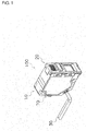
- the photoelectric sensor 100 is used as, for example, a photoelectric switch, an optical distance determination sensor, or an optical displacement sensor. As shown in Fig. 1 , the photoelectric sensor 100 includes a body 10, an attachment 20, and a cord 30.
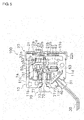
- the body 10 includes a connecting portion 40, a light emitting unit 50, a light receiving unit 60, and a driving mechanism 70 (described below) (all refer to Fig. 5 ) as its internal components. As shown in Figs. 2A to 2C , the body 10 further includes an enclosure 11, and a light emitting window 12a and a light receiving window 12b. An attachment 20 is mounted on the body 10 at a front surface 11a of the enclosure 11 in which the light emitting window 12a and the light receiving window 12b are formed.
- the enclosure 11 is a boxlike member defining the contour of the body 10.
- the enclosure 11 includes seven surfaces, that is, the front surface 11a, a back surface 11b, an upper surface 11c, a lower surface 11d, two side surfaces 11e and 11e, and an inclined surface 11f.
- the front surface 11a is the surface from which light is emitted toward the detection target S, which is located at a predetermined distance from the photoelectric sensor 100, and at which the reflected light is received.
- the attachment 20 is mounted on the front surface 11a.
- the front surface 11a includes the light emitting window 12a for emitting light and the light receiving window 12b for receiving the emitted light and guiding it into the enclosure 11, which are arranged in the long axis direction (vertical direction in the figure).
- the back surface 11b is opposite to the front surface 11a for emitting and receiving light.
- An operational part 71 which is used to operate the driving mechanism 70 (described below), is arranged on the back surface 11b.
- the back surface 11b further has a through-hole 11ba (refer to Fig. 8 ), in which a rotational axis 72 of the operational part 71 is inserted.
- the upper surface 11c joins the upper end of the front surface 11a and the upper end of the back surface 11b, and defines the ceiling of the enclosure 11. As shown in Fig. 2A and Fig. 3 , the upper surface 11c includes, at a position near the front surface 11a, an engagement groove 13a, which is engaged with an engagement portion 22aa of a catch portion 22a of the attachment 20.
- the lower surface 11d is opposite to the upper surface 11c.
- the lower surface 11d joins the lower end of the front surface 11a and the lower end of the back surface 11b, and defines the bottom of the enclosure 11.
- the lower surface 11d includes, at a position near the front surface 11a, an engagement groove 13b, which is engaged with an engagement portion 22ba of a catch portion 22b of the attachment 20.
- the two side surfaces 11e are substantially trapezoidal flat portions defining the sides of the body 10.
- the inclined surface 11f which is arranged below the back surface 11b, is inclined relative to the back surface 11b and to the lower surface 11d.
- a cord holder 31 of a cord 30 is fixed to the inclined surface 11f.
- the light emitting window 12a allows light from the light emitting unit 50 (described below) (refer to Fig. 5 ) arranged in the enclosure 11 to be emitted out of the sensor.
- the surface of the light emitting window 12a is inclined relative to the optical axis of the emitted light to prevent reflected light of the light that has been emitted out of the sensor from entering the light emitting window 12a.
- the light receiving window 12b receives the reflected light of the light that has been emitted from the light emitting window 12a, and guides the received light to the light receiving unit 60 (refer to Fig. 5 ), which is arranged in the enclosure 11.
- the attachment 20 is capable of focusing the light emitted through the light emitting window 12a of the body 10 only in a uniaxial direction that is the horizontal direction.
- the attachment 20 is mounted on the front surface 11a of the body 10. As shown in Figs. 4A and 4B , the attachment 20 includes a flat portion 21, catch portions 22a and 22b, and a cylindrical lens (a second lens, or an aspheric toric lens) 23.
- the flat portion 21 is a flat member arranged in proximity of and along the front surface 11a of the body 10 when the attachment 20 is mounted on the body 10. As shown in Figs. 4A and 4B , the flat portion 21 includes a light emitting portion 21a and an opening 21b.
- the light emitting portion 21a is arranged in the upper half of the flat portion 21.
- the light emitting portion 21a is placed in front of the light emitting window 12a of the body 10 when the attachment 20 is mounted on the body 10.
- the cylindrical lens 23 is attached to the light emitting portion 21a. Light emitted through the light emitting window 12a of the body 10 is emitted out of the sensor after passing through the cylindrical lens 23, which is attached to the light emitting portion 21a.
- the opening 21b is formed in the lower half of the flat portion 21.
- the opening 21b is placed in front of the light receiving window 12b of the body 10 when the attachment 20 is mounted on the body 10.
- the opening 21b is a through-hole formed through the surface of the flat portion 21. Reflected light of the light emitted through the light emitting window 12a of the body 10 passes through the opening 21b and enters the body 10 through the light receiving window 12b.
- the catch portions 22a and 22b are elastic members for mounting the attachment 20 onto the body 10.
- the catch portions 22a and 22b are arranged to protrude perpendicularly from the upper end and the lower end of the flat portion 21.
- the catch portions 22a and 22b include engagement portions 22aa and 22ba at the distal ends of their flat portions that are parallel to the upper surface 11c and the lower surface 11d of the body 10 when the attachment 20 is mounted on the body 10.
- the engagement portions 22aa and 22ba protrude downward and upward from the flat portions of the catch portions 22a and 22b.
- the catch portions 22a and 22b of the engagement portions 22aa and 22ba deform elastically and move along the upper surface 11c and the lower surface 11d, and are engaged with the engagement grooves 13a and 13b at their mounting positions as shown in Fig. 5 . This fixes the attachment 20 on the body 10.
- the cylindrical lens 23 which is attached to the light emitting portion 21a, has a curvature only in a uniaxial direction on the surface vertical to the optical axis.
- the cylindrical lens 23 is attached to the flat portion 21 to focus light in the horizontal direction.
- the cord 30 is connected to an amplifier (not shown) and the photoelectric sensor 100 (body 10). In detail, as shown in Fig. 5 , the cord 30 is connected to the connecting portion 40 arranged in the body 10 with the cord holder 31.
- This structure allows a drive voltage provided from the amplifier and various signals transmitted between the amplifier and the photoelectric sensor 100 to be transmitted and received with the cord 30.
- the connecting portion 40 is arranged at a lower position on the back surface 11b within the enclosure 11 of the body 10
- the connecting portion 40 comes in contact with a plurality of terminals arranged on the cord holder 31 to electrically connect the cord 30 and the body 10.
- the amplifier (not shown) and the photoelectric sensor 100 electrically connect to each other with the cord 30, allowing a drive voltage to be provided to the photoelectric sensor 100 and a detection signal from the photoelectric sensor 100 to be received by the amplifier, which can then determine the presence of the detection target S and other information.
- the light emitting unit 50 emits light toward the detection target S. As shown in Fig. 5 , the light emitting unit 50 is arranged behind the light emitting window 12a of the enclosure 11 of the body 10.
- the light emitting unit 50 includes a laser diode (LD) (light source) 51, a lens holder (lens holding unit) 52, a transmitter lens (first lens) 53.
- LD laser diode
- first lens transmitter lens
- the LD 51 which is a light source for emitting laser light having a predetermined wavelength, is arranged most downstream in the optical axis direction of the light emitting unit 50.
- the LD 51 is arranged at a position slightly nearer the upper surface 11c in the middle of the enclosure 11 of the body 10. In the present embodiment, the LD 51 is fixed inside the body 10.
- the lens holder 52 is arranged to hold the transmitter lens 53.
- the lens holder 52 moves forward and backward in the optical axis direction integrally with the transmitter lens 53 when driven by the driving mechanism 70 (described below).
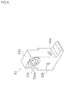
- the lens holder 52 includes a body 52a, a diaphragm 52b, a shaft-receiving hole 52c, and an opening 52d.
- the body 52a is a boxlike member, which accommodates the transmitter lens 53.
- the diaphragm 52b is an opening formed in the body 52a at the position of the optical axis.
- the diaphragm 52b is arranged adjacent to the transmitter lens 53 attached to the body 52a in the optical axis direction.
- the diaphragm 52b is an opening having a different vertical to horizontal ratio.
- the diaphragm 52b limits the passage of the laser light emitted from the LD 51.
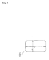
- the diaphragm 52b has the ratio of its length in Y-direction (long axis direction) to its length in X-direction (short axis direction) ranging from 2 to 10.
- the laser beam emitted from the LD 51 is shaped through this diaphragm 52b into a vertical long laser beam, which then enters the transmitter lens 53.
- the ratio of the length in Y-direction to the length in X-direction is more preferably in the range of 2 to 5.
- the shaft-receiving hole 52c receives a shaft 75 of the driving mechanism 70 (described below) inserted through the hole.
- the shaft-receiving hole 52c has, on its inner circumferential surface, a screw portion (screw mechanism) 52ca (refer to Fig. 6 ), which is screwed with a screw portion (screw mechanism) 75a of the shaft 75 (refer to Fig. 8 ).
- the transmitter lens 53 is a symmetrical lens with respect to the optical axis, and has a surface that is rotationally symmetrical about the optical axis.
- the transmitter lens 53 is fixed in the body 52a with adhesive applied into the opening 52d.
- the transmitter lens 53 is arranged adjacent to the diaphragm 52b in the lens holder 52.
- the transmitter lens 53 focuses light passing through the diaphragm 52b, and guides the light in the direction of the light emitting window 12a and the cylindrical lens 23.
- the transmitter lens 53 moves forward and backward in the optical axis direction together with the diaphragm 52b when driven by the driving mechanism 70 (described below). This adjusts the distance between the transmitter lens 53 and the LD 51 and changes the shape of the laser beam.
- the changing shape of the laser beam emitted from the photoelectric sensor 100 when the transmitter lens 53 is moved in the optical axis direction will be described in detail below.
- the light receiving unit 60 receives reflected light of the laser light emitted from the light emitting unit 50 toward the detection target S, and detects the amount of the reflected light. As shown in Fig. 5 , the light receiving unit 60 includes a receiver lens 61, a filter 62, and a light receiving element 63.
- the receiver lens 61 is arranged in proximity of and behind the light receiving window 12b to focus reflected light of the laser light emitted from the light emitting unit 50 onto the detection target S, and to guide the light onto the light receiving element 63.
- the filter 62 removes an unnecessary portion of the laser light that has passed through the receiver lens 61 to improve the integrity of the reflected light detected by the light receiving element 63 and to improve the measurement accuracy.
- the light receiving element 63 receives the reflected light that has passed through the receiver lens 61 and the filter 62, and outputs a light receiving signal generated in accordance with the received amount of the reflected light.
- the light receiving signal is transmitted to an amplifier (not shown) via the connecting portion 40 and the cord 30.
- the amplifier can determine the presence of the detection target S and other information based on, for example, the level of the light receiving signal.
- the driving mechanism 70 is arranged inside the body 10 to extend in the optical axis direction from the back surface 11b.
- the driving mechanism 70 adjusts the distance between the LD 51 and the transmitter lens 53 described above in the optical axis direction by moving the transmitter lens 53. More specifically, the driving mechanism 70 moves the transmitter lens 53 forward and backward relative to the LD 51 on the optical path, with a reference position P0 being the position of the transmitter lens 53 at which the distance between the transmitter lens 53 and the LD 51 is substantially the same as the focal length of the transmitter lens 53.
- the driving mechanism 70 includes the operational part (rotating body) 71, the rotational axis 72, a ring 73, a slidable portion 74, the shaft 75, a coil spring 76, and two flat springs 77.
- the operational part 71 is a cylindrical portion exposed on the back surface 11 of the body 10b.
- its gear 71a is engaged with a gear (not shown) arranged on the back surface 11b to restrict rotation (in a locked state). This restricts rotation of the operational part 71 and fixes the position of the transmitter lens 53.
- the operational part 71 When the operational part 71 is protruded from the back surface 11b of the body 10 (refer to Fig. 8 ), the operational part 71 is rotatable clockwise and counterclockwise (in an adjustable state). Rotating the protruded operational part 71 moves the lens holder 52, to which the transmitter lens 53 is attached, forward and backward in the optical axis direction.
- the rotational axis 72 is a cylindrical portion about which the operational part 71 rotates. As shown in Fig. 8 , the rotational axis 72 connects the operational part 71, which is exposed on the back surface 11b of the body 10, to the slidable portion 74.
- the ring 73 is an O-ring made of rubber, which is set on the outer circumference of the rotational axis 72.
- the ring 73 seals the gap between the through-hole 11ba formed in the back surface 11b of the body 10 and the outer circumferential surface of the rotational axis 72 to prevent foreign matter or water from entering from the back surface 11b.
- the slidable portion 74 is a cylindrical portion formed integrally with the operational part 71 and the rotational axis 72. As shown in Fig. 8 , the end of the slidable portion 74 nearer the back surface 11b is connected to the rotational axis 72.
- the slidable portion 74 includes a recess 74a in the middle in the long axis direction.
- the recess 74a is a portion gradually thinner from the two ends of the slidable portion 74 toward the middle.
- the slidable portion 74 further has a groove 74b at a position nearer the back surface 11b from the recess 74a.
- the groove 74b extends along the outer circumferential surface of the cylindrical slidable portion.
- the shaft 75 is connected to the end of the slidable portion 74 nearer the front surface 11a in a manner incapable of relative rotation. In this structure, a rotating torque generated by the rotating operational part 71 is transmitted to the shaft 75 in a reliable manner through the rotational axis 72 and the slidable portion 74.
- the shaft 75 includes a large-diameter portion 75c at its end nearer the front surface 11a.
- the shaft 75 further includes a small-diameter portion 75b at a position nearer the back surface 11b than the large-diameter portion 75c.
- the small-diameter portion 75b is placed into the shaft-receiving hole 52c of the lens holder 52 and then into an area defined by the inner circumference of the coil spring 76.
- the small-diameter portion 75b of the shaft 75 further includes the screw portion 75a (refer to Fig. 8 ).
- the screw portion 75a is screwed with the screw portion 52ca formed at the shaft-receiving hole 52c of the lens holder 52 (refer to Fig. 6 ). Rotating the shaft 75 moves the lens holder 52 in the optical axis direction.
- rotating the operational part 71 which is connected to the shaft 75, moves the lens holder 52 forward and backward in the optical axis direction. More specifically, rotating the operational part 71 clockwise or counterclockwise adjusts the distance between the LD 51 fixed in the body 10 and the transmitter lens 53.
- the coil spring 76 is mounted on the outer circumference of the small-diameter portion 75b of the shaft 75 including the screw portion 75a.
- the coil spring 76 is sandwiched between the large-diameter portion 75c, which is an end of the shaft 75 nearer the front surface 11a and the surface of the lens holder 52 nearer the front surface 11a.
- the coil spring 76 constantly presses the lens holder 52 toward the back surface 11b.
- the pressing force applied by the coil spring 76 reduces rattle between the screw portion 52ca of the lens holder 52 and the screw portion 75a of the shaft 75 that are screwed together.
- This structure stabilizes the arrangement of the diaphragm 52b and the transmitter lens 53, through which the laser light emitted from the LD 51 passes.
- the two flat springs 77 are fixed inside the enclosure 11, with the slidable portion 74 being sandwiched between the upper and lower flat springs 77 in cross-section. Portions of the flat springs 77 (bent portions 77a) come in contact with the outer circumference of the slidable portion 74. In detail, the flat springs 77 apply a pressing force pressing the slidable portion 74 from above and from below in the radial direction of the cylindrical slidable portion 74.
- the two flat springs 77 include the bent portions 77a on their ends coming in contact with the slidable portion 74.
- the slidable portion 74 moves in the direction of the rotational axis 72, with the bent portions 77a coming in contact with the recess 74a or the groove 74b on the outer circumferential surface of the slidable portion 74 and applying a pressing force in the radial direction to the slidable portion 74.
- the slidable portion 74 When the operational part 71 is protruded to unlock the locked state, the slidable portion 74 is engaged into the recess 74a to allow the operator to determine that the operational part 71 has entered the adjustable state. When the slidable portion 74 is moved along the shaft 75, the bent portions 77a slide on the recess 74a while applying a pressing force in the radial direction. This stabilizes the bent portions 77a on the narrowest part of the recess 74a. This structure prevents the operational part 71 from being held at an unstable position between the locked state and the adjustable state and from being operated erroneously.
- the bent portions 77a are disengaged from the groove 74b, and move in contact with the surface that is inclined downward from the back surface 11b toward the front surface 11a, among the two inclined surfaces defining the recess 74a of the slidable portion 74.
- the two flat springs 77 press the slidable portion 74 toward the back surface 11b, assisting the protruding operation of the operational part 71.
- the photoelectric sensor 100 having the above-described structure according to the present embodiment enables illumination with a line beam having an intended oval shape when the attachment 20 has been removed from the photoelectric sensor 100 (refer to Fig. 3 ).
- the photoelectric sensor 100 combines the diaphragm 52b, which has a smaller width in X-direction and a larger width in Y-direction than in X-direction, and the transmitter lens 53, which is a symmetrical lens with respect to the optical axis, to produce a line beam having an intended oval shape.
- a laser beam B emitted from the LD 51 in X-direction passes through the opening of the diaphragm 52b, and then substantially collimated by the transmitter lens 53 and is applied to the detection target S.
- the length of the laser beam in X-direction applied to the detection target S is substantially the same as the dimension of the opening of the diaphragm 52b in X-direction.
- the laser beam B emitted from the LD 51 in Y-direction passes through the opening of the diaphragm 52b, and then is substantially collimated by the transmitter lens 53 and applied to the detection target S.
- the length of the laser beam B in Y-direction applied to the detection target S is substantially the same as the dimension of the opening of the diaphragm 52b in Y-direction.
- the laser beam B applied to the detection target S is shaped into an oval beam that is longer in Y-direction than in X-direction, in conformance with the dimensions of the diaphragm 52b. This enables illumination of the target with the line beam having an intended oval cross-section. As a result, the photoelectric sensor 100 increases the detectable range and increases the coverage for averaging.
- the photoelectric sensor 100 enables illumination with a line beam having an oval shape as described above. Additionally, the photoelectric sensor 100 enables switching of the laser beam applied to the detection target (target) S between different beams including a vertically long beam, a horizontally long beam, and a circular spot by adjusting the distance between the LD 51 and the transmitter lens 53 using the driving mechanism 70.
- the laser beam emitted from the LD 51 passes through the transmitter lens 53 and then passes through the diaphragm 52b having a vertically long opening that is longer in Y-direction (vertical direction) than in X-direction (horizontal direction).
- the laser beam immediately before passing through the cylindrical lens 23 of the attachment 20 is shaped into a vertically long beam having dimensions being affected by the dimensions of the diaphragm 52b.
- the cylindrical lens 23 has a curvature only in X-direction corresponding to the short axis direction of the diaphragm 52b. Assuming these conditions, the operation of producing laser beams with the different shapes will now be described.
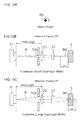
- the photoelectric sensor 100 produces a laser beam having substantially the same length in X-direction and in Y-direction by adjusting the distance between the LD 51 and the transmitter lens 53, and emits the spot beam B0 shown in Fig. 10A .
- the transmitter lens 53 when the transmitter lens 53 is at a reference position P0, which is away from the light emitting surface of the LD 51 by the focal length of the transmitter lens 53, the laser beam B passing through the diaphragm 52b, which is substantially rectangular and longer in Y-direction than in X-direction, is substantially collimated by the transmitter lens 53.
- the diaphragm 52b has a smaller width in X-direction.
- the light beam passing through the transmitter lens 53 thus has a smaller width in this direction.
- the diaphragm 52b has a larger width in Y-direction than in X-direction.
- the light beam passing through the transmitter lens 53 thus has a larger width in Y-direction than in X-direction.
- the laser beam B passing through the transmitter lens 53 is subsequently focused by the curved surface of the cylindrical lens 23 having a curvature in X-direction.
- the laser beam B is focused, with the focal point being placed in front of the detection target S as viewed from the transmitter lens 53, and is applied to the surface of the detection target S.
- the laser beam B passing through the transmitter lens 53 subsequently passes through the cylindrical lens 23 without being affected by the cylindrical lens 23 that has no curvature in Y-direction.
- the laser beam B is focused, with the focal point being placed behind the detection target S as viewed from the transmitter lens 53, and is applied to the surface of the detection target S.
- the distance dl from the surface of the detection target S to the focal point in X-direction is substantially the same as the distance d2 from the surface of the detection target S to the focal point in Y-direction.
- the surface of the detection target S is illuminated with the light beam having substantially the same width in X-direction and in Y-direction.
- the photoelectric sensor produces the spot beam B0 having a substantially circular shape shown in Fig. 10A .
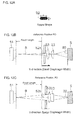
- the photoelectric sensor 100 can produce a vertically long laser beam that is short in X-direction and long in Y-direction by adjusting the distance between the LD 51 and the transmitter lens 53, and emits the vertically long line beam B1 shown in Fig. 11A .
- the laser beam B passing thorough the substantially rectangular diaphragm 52b that is longer in Y-direction than in X-direction is substantially collimated while widening slightly through the transmitter lens 53.
- the diaphragm 52b has a smaller width in X-direction.
- the light beam passing through the transmitter lens 53 thus has a smaller width in this direction.
- the diaphragm 52b has a larger width in Y-direction than in X-direction.
- the light beam passing through the transmitter lens 53 thus has a larger width in Y-direction than in X-direction.
- the laser beam B passing through the transmitter lens 53 is subsequently focused by the curved surface of the cylindrical lens 23 having a curvature in X-direction, and is applied to the surface of the detection target S.
- the laser beam B passing through the transmitter lens 53 subsequently passes through the cylindrical lens 23 without being affected by the cylindrical lens 23 that has no curvature in X-direction.
- the laser beam B is then applied to the surface of the detection target S while the width of the light beam is remaining large.
- the vertically long line beam B1 that is narrower in X-direction and wider in Y-direction is applied to the surface of the detection target S.
- the photoelectric sensor produces the vertically long line beam B1 shown in Fig. 11A having the dimensions in conformance with the diaphragm 52b.
- the vertically long line beam B1 shown in Fig. 11A can have dimensions in X-direction and Y-direction that are changeable by adjusting the distance at which the transmitter lens 53 is arranged relative to the LD 51.
- the photoelectric sensor 100 can produce a horizontally long laser beam that is long in X-direction and short in Y-direction by adjusting the distance between the LD 51 and the transmitter lens 53, and emits the horizontally long line beam B2 shown in Fig. 12A .
- the transmitter lens 53 when the transmitter lens 53 is moved away from the LD 51 from the reference position P0, which is away from the light emitting surface of the LD 51 by the focal length of the transmitter lens 53, the laser beam B passing through the substantially rectangular diaphragm 52b that is longer in Y-direction than in X-direction enters the cylindrical lens 23 while being focused by the transmitter lens 53.
- the diaphragm 52b has a smaller width in X-direction.
- the light beam passing through the transmitter lens 53 thus has a smaller width in this direction.
- the diaphragm 52b has a larger width in Y-direction than in X-direction.
- the light beam passing through the transmitter lens 53 thus has a larger width in Y-direction than in X-direction.
- the laser beam B passing through the transmitter lens 53 is subsequently focused by the curved surface of the cylindrical lens 23 having a curvature in X-direction.
- the laser beam B forms the focal point in front of the detection target S as viewed from the transmitter lens 53, and is applied to the surface of the detection target S while the width of the light beam is remaining large.
- the laser beam B passing through the transmitter lens 53 subsequently passes through the cylindrical lens 23 without being affected by the cylindrical lens 23 that has no curvature in Y-direction.
- the laser beam B is applied to the surface of the detection target S while being focused by the transmitter lens 53 and being narrower.
- the horizontally long line beam B2 that is wider in X-direction and narrower in Y-direction is applied to the surface of the detection target S.
- the photoelectric sensor produces the horizontally long line beam B2 shown in Fig. 12A having the dimensions resulting from rotating the diaphragm 52b by 90 degrees.
- the vertically long line beam B1 shown in Fig. 12A can have dimensions in X-direction and Y-direction that are changeable by adjusting the distance at which the transmitter lens 53 is arranged relative to the LD 51.
- the photoelectric sensor may have a simple structure shown in Figs. 9A and 9B without including the attachment (cylindrical lens) and the driving mechanism when the sensor can produce an oval line beam by combining a diaphragm with intended dimensions and a lens of an appropriate type.
- Figs. 9A and 9B includes a diaphragm having an opening with different vertical and horizontal dimensions and a focusing lens (first lens), the invention should not be limited to this structure.
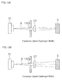
- the structure may include a diaphragm 152b having an opening with substantially the same vertical and horizontal dimensions and an asymmetric lens 123 with respect to the optical axis (cylindrical lens) as shown in Figs. 13A and 13B .
- the diaphragm 152b has a substantially rectangular opening or a substantially circular opening.
- the laser beam having substantially the same length in X-direction and in Y-direction is focused by the cylindrical lens 123 only in one predetermined direction (in X-direction in the example of Fig. 13A ) to produce a line beam with an intended oval shape.
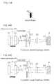
- the transmitter lens 53 may be fixed and the LD 51 may be moved forward and backward along the optical path.
- the LD 51 may be moved forward from the reference position P0 toward the transmitter lens 53 (to the right in the figure) as shown in Figs. 14B and 14C .
- the LD 51 may be moved backward from the reference position P0 toward the transmitter lens 53 (to the left in the figure) as shown in Figs. 15B and 15C .
- the structures according to embodiments of the present invention can produce the advantages described above when the structures can adjust the distance between the LD 51 functioning as the light source and the transmitter lens 53 functioning as the first lens based on the reference position set at the focal length of the lens.
- the mechanism for moving the light source may be the same as the driving mechanism 70 described in the above embodiment.
- the LD (light source) 51, the transmitter lens (first lens) 53, the cylindrical lens (second lens) 23, the diaphragm 52b, and the driving mechanism 70 forming the light emitting unit of the present invention may be integrally arranged in a single package.
- the diaphragm may be horizontally long, or is longer in X-direction than in Y-direction, to limit a part of the optical path of the laser beam B emitted from the LD 51.
- the cylindrical lens (aspheric toric lens) having a curvature only in a uniaxial direction needs to be rotated by 90 degrees in accordance with the diaphragm rotated by 90 degrees.
- the diaphragm and the cylindrical lens are arranged to align the short axis direction of the diaphragm with the direction of the surface of the cylindrical lens having a curvature.
- This arrangement enables the photoelectric sensor to produce both a horizontally long laser beam that is long in X-direction and a vertically long laser beam that is long in Y-direction by adjusting the distance between the LD and the transmitter lens based on the reference position in the same manner as described above.
- the opening of the diaphragm may be substantially circular or substantially oval.
- the diaphragm may be fixed and the transmitter lens may move independently.
- the shape of the light passing through the diaphragm can be maintained when the distance between the diaphragm and the transmitter lens is fixed. It is thus preferable that the diaphragm and the transmitter lens move integrally as in the above embodiment.
- a concave aspheric toric lens may be used instead of the convex cylindrical lens.
- Such a lens also has a curvature only in a uniaxial direction, and thus produces the same advantages as described in the above embodiment.
- a light emitting diode may be used as the light source instead of the LD.
- the light emitting unit of the present invention may be used for a photoelectric sensor other than the reflective photoelectric sensor.
- the light emitting unit may be used for a diffuse-reflective photoelectric sensor and a definite-reflective photoelectric sensor.
- the light emitting unit may be used for a coaxial photoelectric sensor in which a single window functions commonly as the light emitting window and the light receiving window.
- the photoelectric sensor of the present invention can freely adjust the long axis direction of a line beam or the length of a line beam without changing the direction in which the unit is mounted or without replacing the attachment for producing a line beam.
- the present invention is thus applicable not only to photoelectric sensors but is also applicable to various other apparatuses including light emitting apparatuses and laser machining apparatuses.
Landscapes
- Engineering & Computer Science (AREA)
- Physics & Mathematics (AREA)
- Computer Networks & Wireless Communication (AREA)
- General Physics & Mathematics (AREA)
- Radar, Positioning & Navigation (AREA)
- Remote Sensing (AREA)
- Electromagnetism (AREA)
- Optical Radar Systems And Details Thereof (AREA)
- Switches Operated By Changes In Physical Conditions (AREA)
- Geophysics And Detection Of Objects (AREA)
Abstract

Description
- The present invention relates to a photoelectric sensor that illuminates a target object with light and detects its reflected light.
- For example,
Patent Literature 1 describes a photoelectric sensor incorporating an optional unit including a cylindrical lens that has a curvature only in a uniaxial direction. The photoelectric sensor moves its transmitter lens forward and backward along the optical axis of light emitted from a light emitter to adjust the spot diameter of a circular beam or to adjust the length of a line beam in the uniaxial direction. - The structure described in the above publication improves the degree of freedom in various settings of a light beam emitted from a long-distance photoelectric sensor.
- Patent Literature 1: Japanese Unexamined Patent Application Publication No.
2004-71366 - However, the above structure known in the art has the problems described below.
- With a light beam having a small beam diameter, the reflective photoelectric sensor described in the above publication can detect a target erroneously depending on the surface conditions, when the detection is affected by protrusions and recesses on the surface of the detection target. To prevent such erroneous detection, the photoelectric sensor uses a line beam and averages the light receiving amount.
- However, the photoelectric sensor in actual use can fail to detect the target even with a line beam. To overcome this, the equipment installed in the actual site may include an additional photoelectric sensor, such as a transmissive photoelectric sensor or a retroreflective photoelectric sensor.
- It is an object of the present invention to provide a light emitting unit that produces a line beam expanded in a longitudinal direction and also in a width direction to increase the detectable range and increase the coverage for averaging, and also to provide a photoelectric sensor including such a light emitting unit.
- A reflective photoelectric sensor according to a first aspect of the invention illuminates light to a predetermined distance from the sensor and detects reflected light from a target located at that predetermined distance. The photoelectric sensor includes a light source, a diaphragm, and a lens. The diaphragm blocks a peripheral portion of light emitted from the light source. The lens converts light passing through the diaphragm to a substantially collimated light beam. The light beam has an oval cross-section having a ratio of a length of a long axis to a length of a short axis ranging from 2 to 10 inclusive at the predetermined distance. The predetermined distance may be, in particular, a nominal distance at which the target is estimated to be placed when the sensor is used. That is to say, the predetermined distance is within a detection range for which the sensor has been designed.
- The sensor produces a line beam having an intended oval shape by combining the diaphragm, which blocks a peripheral portion of light emitted from the light source and limits the range of light to pass through, and the lens, which converts light passing through the diaphragm to a substantially collimated light beam.
- The lengths of the long axis and the short axis of the oval cross-section may be determined by using, for example, the half width of the graph showing the wavelength distribution of laser beams emitted from the light source. The oval cross-section may not be in a complete oval shape, but may be in a substantially rectangular shape. The substantially collimated light beam may not be a completely collimated light beam, but may include a slightly diffusing light beam or a slightly focused light beam. Further, substantial collimation includes substantially collimating light that is focused or diffuses in at least a uniaxial direction perpendicular to the optical axis. The lens may not be a focus lens but may include a cylindrical lens that has a curvature in a predetermined first direction and has no curvature in a second direction perpendicular to the first direction.
- This enables a target to be illuminated with a line beam having an intended size and having an oval cross-section and enables the dimensions of the line beam to be adjusted in the long axis direction and in the short axis direction. When this reflective photoelectric sensor is mounted on a photoelectric sensor, the photoelectric sensor can increase the detectable range and increase the coverage for averaging.
- The reflective photoelectric sensor according to a second aspect of the invention is the reflective photoelectric sensor of the first aspect of the invention in which the light beam having an oval cross-section having a ratio of the long axis length to the short axis length ranging from 2 to 5 inclusive at the predetermined distance.
- The more preferable range is specified for the ratio of the lengths of the long axis and the short axis of the light beam with which the target is illuminated.
- This enables a target to be illuminated with a line beam having an intended size and having an oval cross-section and enables the dimensions of the line beam to be adjusted in the long axis direction and in the short axis direction.
- The reflective photoelectric sensor according to a third aspect of the invention is the reflective photoelectric sensor of the first or second aspect of the invention in which the diaphragm has an opening with a different ratio of vertical and horizontal lengths, and the lens is configured to substantially collimate a light beam passing through the opening of the diaphragm.
- The sensor produces a line beam having an intended oval shape by combining the diaphragm, which has the opening with a different ratio of vertical and horizontal lengths, and the lens, which produces substantially collimated light.
- The optical axis is a straight line that is aligned with the center of the lens and is perpendicular to the lens surface.
- The light beam passing through the diaphragm is shaped into an oval shape in conformance with the dimensions of the opening of the diaphragm, and is substantially collimated by the lens. This produces a light beam having an intended oval cross-section in conformance with the dimensions of the opening of the diaphragm.
- The reflective photoelectric sensor according to a fourth aspect of the invention is the reflective photoelectric sensor of the first or second aspect of the invention in which the diaphragm has an opening with substantially equal vertical and horizontal lengths. The lens has a curvature only in a uniaxial direction in a plane perpendicular to an optical axis thereof, and is an asymmetric lens with respect to the optical axis configured to substantially collimate light that is focused or diffuses at least in the uniaxial direction perpendicular to the optical axis.
- The sensor produces a line beam having an oval cross-section by combining the diaphragm, which has the opening with substantially the same ratio of vertical and horizontal lengths, and the asymmetric lens, which produces substantially collimated light.
- The optical axis is a straight line that is aligned with the center of the lens and is perpendicular to the lens surface.
- The light beam passing through the diaphragm is shaped into a substantially circular shape in conformance with the dimensions of the opening of the diaphragm, but is substantially collimated only in the first direction in a plane perpendicular to the optical axis. As a result, the light beam widens in the second direction perpendicular to the first direction at the plane perpendicular to the optical axis without being affected by the lens. This produces a light beam having an intended oval cross-section that is long in the second direction.
- The reflective photoelectric sensor according to a fifth aspect of the invention is the reflective photoelectric sensor of one of the first to fourth aspects of the invention in which the lens includes a first lens that has a surface rotationally symmetrical about an optical axis thereof and is configured to focus light emitted from the light source, and a second lens that has a curvature only in a first direction in a plane perpendicular to incident light from the first lens and is flat and has no curvature in a second direction perpendicular to the first direction. The diaphragm is arranged such that a direction of the short axis is substantially parallel to the first direction of the second lens. The reflective photoelectric sensor further includes a driving mechanism configured to move the first lens forward or backward relative to the light source from a reference position that is away from a light emitting surface of the light source by a focal length of the first lens in an optical axis direction of light emitted from the light source.
- The lens includes the first lens for focusing light and the second lens that has a curvature only in the first direction in the plane perpendicular to the optical axis. The diaphragm is arranged such that its short axis direction is substantially parallel to the first direction of the second lens. The driving mechanism adjusts the distance between the light source and the first lens.
- The optical axis is a straight line that is aligned with the center of the lens and is perpendicular to the lens surface.
- When the first lens is at the reference position set based on the focal length of the first lens, the lens has its focal point in the vicinity of the target both in the vertical direction and in the horizontal direction. A narrow light beam having a different ratio of the vertical and horizontal lengths passing through the diaphragm then slightly widens in the shorter length direction when passing through the second lens. The resulting beam has substantially the same ratio of the vertical and horizontal lengths. This produces a substantially circular spot beam for illuminating the target.
- When, for example, the first lens is moved from the reference position toward the light emitting surface, or specifically when the distance between the first lens and the light emitting surface is reduced, the light passing through the first lens slightly widens and travels toward the second lens without being focused. The light passing through the second lens, which has slightly widened through the first lens, is slightly focused by the second lens only in the first direction in which the lens has a curvature. The light passing through the first and second lenses will undergo substantial canceling out of the effects by the first and second lenses in the first direction. The light affected solely by the shape of the diaphragm is emitted from the reflective photoelectric sensor. This enables the target to be illuminated with a line beam shaped in the same direction as the diaphragm.
- When, for example, the first lens is moved from the reference position in the direction opposite to the light emitting surface, or specifically when the distance between the light emitting surface and the first lens is increased, the light passing through the first lens is focused more by the first lens than when the first lens is at the reference position, and travels toward the second lens. A narrow and long light beam having a different ratio of vertical and horizontal lengths passing through the diaphragm has the focal point moving to a position in front of the target as viewed from the first lens, and is affected by the second lens in the first direction and is further focused. The narrow and long beam passing through the diaphragm moves its focal point in the short axis direction (first direction), and widens in the first direction in which the second lens has a curvature. Although not affected by the second lens, the portion of the light in the long axis direction (second direction) passing through the diaphragm can be shortened because of the initial setting in which the first lens will have the focal point in the vicinity of the target when the distance between the first lens and the light emitting surface is increased. This produces a line beam resulting from rotating the shape of the diaphragm by 90 degrees.
- The length of the line beam in the long axis direction can be adjusted in accordance with the distance by which the first lens is moved from the above reference position.
- As described above, adjusting the distance between the light emitting surface of the light source and the first lens allows illumination with a substantially circular spot beam and a line beam having the lengths adjustable in the two perpendicular axis directions (first and second directions), without changing the direction in which the reflective photoelectric sensor is mounted or replacing the attachment.
- The reflective photoelectric sensor according to a sixth aspect of the invention is the reflective photoelectric sensor of the fifth aspect of the invention in which when the first lens is at the reference position, the light source, the first lens, and the second lens are arranged such that the focal point near the target is in front of the target in the first direction and is behind the target in the second direction as viewed from the first lens.
- When the first lens is at the reference position, the light source and the first and second lenses are arranged such that the focal point of the light passing through the first and second lenses is in front of the target in the first direction, and is behind the target in the second direction.
- Moving the first lens forward and backward relative to the light source in the optical axis direction based on the reference position enables the laser beam to be adjusted into a spot beam, a line beam that is long in the first direction, and a line beam that is long in the second direction perpendicular to the first direction.
- The reflective photoelectric sensor according to a seventh aspect of the invention is the reflective photoelectric sensor of the fifth or sixth aspect of the invention in which the driving mechanism moves the first lens in the optical axis direction of light emitted from the light source.
- The driving mechanism moves the first lens to adjust the distance between the light source and the first lens.
- Moving the first lens forward and backward in the optical axis direction based on the reference position allows selective emission of a spot beam, a horizontal long oval line beam, and a vertically long oval line beam.
- The reflective photoelectric sensor according to an eighth aspect of the invention is the reflective photoelectric sensor of the fifth or sixth aspect of the invention in which the driving mechanism moves the first lens and the diaphragm in the optical axis direction of light emitted from the light source.
- In this structure, the driving mechanism moves the diaphragm together with the first lens to adjust the distance between the light source and the first lens.
- The distance between the first lens and the diaphragm is constant although the driving mechanism adjusts the distance between the light source and the first lens. This stabilizes the shape of the light beam passing through the diaphragm and the first lens.
- The reflective photoelectric sensor according to a ninth aspect of the invention is the reflective photoelectric sensor of the eighth aspect of the invention further including a lens holder for holding the first lens. The lens holder includes the diaphragm arranged on a plane substantially perpendicular to the optical axis direction of light emitted from the light source.
- In this structure, the diaphragm is arranged on the plane of the lens holding unit for holding the first lens substantially perpendicular to the optical axis direction.
- The driving mechanism moves the lens holding unit in the optical axis direction to allow the first lens and the diaphragm to move integrally.
- The reflective photoelectric sensor according to a tenth aspect of the invention is the reflective photoelectric sensor according to one of the fifth to ninth aspects of the invention in which the driving mechanism moves the light source in a direction of light emitted from the light source.
- In this structure, the driving mechanism moves the light source to adjust the distance between the light source and the first lens.
- Moving the light source forward and backward in the optical axis direction based on the reference position allows selective emission of a spot beam, a horizontally long oval line beam, and a vertically long oval line beam.
- The reflective photoelectric sensor according to an eleventh aspect of the invention is the reflective photoelectric sensor of one of the fifth to tenth aspects of the invention further including an enclosure accommodating at least the light source, the first lens, and the diaphragm. The driving mechanism includes a rotating body exposed outside the enclosure, and a screw mechanism configured to move the first lens in the optical axis direction by rotating the rotating body.
- In this structure, the driving mechanism rotates the rotating body exposed on the enclosure, which accommodates the light source, the first lens, and the diaphragm. As a result, the screw mechanism moves the first lens.
- Simply rotating the rotating body arranged outside the enclosure adjusts the distance between the light source and the first lens. This easily allows emission of a laser beam having an intended shape.
- The reflective photoelectric sensor according to a twelfth aspect of the invention is the reflective photoelectric sensor of one of the fifth to eleventh aspects of the invention in which the second lens is an aspheric toric lens.
- In this structure, the aspheric toric lens is used as the second lens having a curvature only in the first direction.
- This structure widens only the width of the laser beam in the short axis direction by using the second lens.
- The reflective photoelectric sensor according to a thirteenth aspect of the invention is the reflective photoelectric sensor of the twelfth aspect of the invention in which the second lens is a cylindrical lens.
- In this structure, the cylindrical lens is used as the aspheric toric lens (second lens) having a curvature only in the first direction.
- This structure widens only the width of the laser beam in the short axis direction by using the cylindrical lens as the second lens.
- The light emitting unit of the present invention is capable of illuminating a target with a line beam having an intended size and having an oval cross-section, and is capable of adjusting the dimensions of the line beam in the long axis direction and in the short axis direction.
-
-
Fig. 1 is an overall perspective view showing the structure of a photoelectric sensor according to one embodiment of the present invention. -
Figs. 2A, 2B, and 2C are a side view, a front view, and a back view of the photoelectric sensor shown inFig. 1 . -
Fig. 3 is a perspective view showing the structure of a body of the photoelectric sensor shown inFig. 1 . -
Figs. 4A and 4B are perspective views showing the structure of an attachment to be mounted on the body of the photoelectric sensor shown inFig. 1 . -
Fig. 5 is a cross-sectional view taken along line A-A inFig. 2B . -
Fig. 6 is a perspective view showing the structure of a lens holder for holding a transmitter lens included in the light emitting unit shown inFig. 5 . -
Fig. 7 is a diagram showing the vertical to horizontal ratio of a diaghram arranged in the lens holder shown inFig. 6 . -
Fig. 8 is a cross-sectional view showing the main components of a driving mechanism in the photoelectric sensor ofFig. 5 . -
Figs. 9A and 9B are schematic views describing the structure for emitting an oval line beam from the photoelectric sensor ofFig. 1 . -
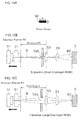
Fig. 10A is a diagram showing the beam shape formed when the transmitter lens included in the photoelectric sensor ofFig. 1 is arranged at a reference position, andFigs. 10B and 10C are schematic views of the corresponding arrangements of the sensor components in X-direction and Y-direction. -
Fig. 11A is a diagram showing the beam shape formed when the transmitter lens included in the photoelectric sensor ofFig. 1 has moved toward a laser diode (LD) from the reference position, andFigs. 11B and 11C are schematic views showing the corresponding arrangements of the sensor components in X-direction and Y-direction. -
Fig. 12A is a diagram showing the beam shape formed when the transmitter lens included in the photoelectric sensor ofFig. 1 has moved away from the LD from the reference position, andFigs. 12B and 12C are schematic views showing the corresponding arrangements of the sensor components in X-direction and Y-direction. -
Figs. 13A and 13B are schematic views showing the structure for emitting an oval line beam from a photoelectric sensor according to another embodiment of the present invention. -
Fig. 14A is a diagram showing the beam shape formed when an LD arranged in a photoelectric sensor including a light emitting unit of the other embodiment of the present invention has moved toward a transmitter lens from a reference position, andFigs. 14B and 14C are schematic views showing the corresponding arrangements of the sensor components in X-direction and Y-direction. -
Fig. 15A is a diagram showing the beam shape formed when the LD arranged in the photoelectric sensor including the light emitting unit according to the other embodiment of the present invention has moved away from the transmitter lens from the reference position, andFig. 15B and 15C are schematic views showing the corresponding arrangements of the sensor components in X-direction and Y-direction. - Embodiments of the present invention will now be described with reference to the drawings. To avoid redundancy and to facilitate understanding of persons skilled in the art, for example, matters known in the art may not be described in detail and components that are substantially the same as the components described may not be described.
- The following description and the accompanying drawings are provided by the applicant to enable persons skilled in the art to fully understand the contents of the present invention, and are not intended to limit the subject matter claimed.
- A
photoelectric sensor 100 according to one embodiment of the present invention will now be described with reference toFigs. 1 to Fig. 12C . - In the description below, the direction being forward or backward refers to the direction determined by assuming that the surface onto which a laser beam is applied from the
photoelectric sensor 100 is the front surface. The direction being upward or downward and the direction being vertical is the direction along the long axis of afront surface 11 of thephotoelectric sensor 100. The direction to the left or to the right or being horizontal is the forward or backward direction and the direction orthogonal to the long axis direction. - The
photoelectric sensor 100 according to the present embodiment is a reflective photoelectric sensor that receives reflected light of its emitted light and detects the presence of a detection target (target) S and other information. Thephotoelectric sensor 100 is used as, for example, a photoelectric switch, an optical distance determination sensor, or an optical displacement sensor. As shown inFig. 1 , thephotoelectric sensor 100 includes abody 10, anattachment 20, and acord 30. - The
body 10 includes a connectingportion 40, a light emitting unit 50, a light receiving unit 60, and a driving mechanism 70 (described below) (all refer toFig. 5 ) as its internal components. As shown inFigs. 2A to 2C , thebody 10 further includes anenclosure 11, and alight emitting window 12a and alight receiving window 12b. Anattachment 20 is mounted on thebody 10 at afront surface 11a of theenclosure 11 in which thelight emitting window 12a and thelight receiving window 12b are formed. - The
enclosure 11 is a boxlike member defining the contour of thebody 10. Theenclosure 11 includes seven surfaces, that is, thefront surface 11a, aback surface 11b, anupper surface 11c, alower surface 11d, twoside surfaces inclined surface 11f. - The
front surface 11a is the surface from which light is emitted toward the detection target S, which is located at a predetermined distance from thephotoelectric sensor 100, and at which the reflected light is received. As shown inFig. 2A and other figures, theattachment 20 is mounted on thefront surface 11a. As shown inFig. 3 , thefront surface 11a includes thelight emitting window 12a for emitting light and thelight receiving window 12b for receiving the emitted light and guiding it into theenclosure 11, which are arranged in the long axis direction (vertical direction in the figure). - As shown in
Figs. 2A and 2C , theback surface 11b is opposite to thefront surface 11a for emitting and receiving light. Anoperational part 71, which is used to operate the driving mechanism 70 (described below), is arranged on theback surface 11b. Theback surface 11b further has a through-hole 11ba (refer toFig. 8 ), in which arotational axis 72 of theoperational part 71 is inserted. - The
upper surface 11c joins the upper end of thefront surface 11a and the upper end of theback surface 11b, and defines the ceiling of theenclosure 11. As shown inFig. 2A andFig. 3 , theupper surface 11c includes, at a position near thefront surface 11a, anengagement groove 13a, which is engaged with an engagement portion 22aa of acatch portion 22a of theattachment 20. - The
lower surface 11d is opposite to theupper surface 11c. Thelower surface 11d joins the lower end of thefront surface 11a and the lower end of theback surface 11b, and defines the bottom of theenclosure 11. As shown inFig. 2A , thelower surface 11d includes, at a position near thefront surface 11a, an engagement groove 13b, which is engaged with an engagement portion 22ba of acatch portion 22b of theattachment 20. - The two
side surfaces 11e are substantially trapezoidal flat portions defining the sides of thebody 10. - The
inclined surface 11f, which is arranged below theback surface 11b, is inclined relative to theback surface 11b and to thelower surface 11d. Acord holder 31 of acord 30 is fixed to theinclined surface 11f. - The
light emitting window 12a allows light from the light emitting unit 50 (described below) (refer toFig. 5 ) arranged in theenclosure 11 to be emitted out of the sensor. The surface of thelight emitting window 12a is inclined relative to the optical axis of the emitted light to prevent reflected light of the light that has been emitted out of the sensor from entering thelight emitting window 12a. - The
light receiving window 12b receives the reflected light of the light that has been emitted from thelight emitting window 12a, and guides the received light to the light receiving unit 60 (refer toFig. 5 ), which is arranged in theenclosure 11. - The internal components of the
body 10 will be described below in detail. - The
attachment 20 is capable of focusing the light emitted through thelight emitting window 12a of thebody 10 only in a uniaxial direction that is the horizontal direction. Theattachment 20 is mounted on thefront surface 11a of thebody 10. As shown inFigs. 4A and 4B , theattachment 20 includes aflat portion 21,catch portions - The
flat portion 21 is a flat member arranged in proximity of and along thefront surface 11a of thebody 10 when theattachment 20 is mounted on thebody 10. As shown inFigs. 4A and 4B , theflat portion 21 includes alight emitting portion 21a and anopening 21b. - As shown in
Fig. 4A , thelight emitting portion 21a is arranged in the upper half of theflat portion 21. Thelight emitting portion 21a is placed in front of thelight emitting window 12a of thebody 10 when theattachment 20 is mounted on thebody 10. Thecylindrical lens 23 is attached to thelight emitting portion 21a. Light emitted through thelight emitting window 12a of thebody 10 is emitted out of the sensor after passing through thecylindrical lens 23, which is attached to thelight emitting portion 21a. - As shown in
Fig. 4A , theopening 21b is formed in the lower half of theflat portion 21. Theopening 21b is placed in front of thelight receiving window 12b of thebody 10 when theattachment 20 is mounted on thebody 10. Theopening 21b is a through-hole formed through the surface of theflat portion 21. Reflected light of the light emitted through thelight emitting window 12a of thebody 10 passes through theopening 21b and enters thebody 10 through thelight receiving window 12b. - As shown in
Figs. 4A and Fig. 4B , thecatch portions attachment 20 onto thebody 10. Thecatch portions flat portion 21. Thecatch portions upper surface 11c and thelower surface 11d of thebody 10 when theattachment 20 is mounted on thebody 10. - As shown in
Fig. 4B , the engagement portions 22aa and 22ba protrude downward and upward from the flat portions of thecatch portions attachment 20 is mounted on thebody 10, thecatch portions upper surface 11c and thelower surface 11d, and are engaged with theengagement grooves 13a and 13b at their mounting positions as shown inFig. 5 . This fixes theattachment 20 on thebody 10. - As shown in
Figs. 4A and 4B , thecylindrical lens 23, which is attached to thelight emitting portion 21a, has a curvature only in a uniaxial direction on the surface vertical to the optical axis. In the present embodiment, thecylindrical lens 23 is attached to theflat portion 21 to focus light in the horizontal direction. - The
cord 30 is connected to an amplifier (not shown) and the photoelectric sensor 100 (body 10). In detail, as shown inFig. 5 , thecord 30 is connected to the connectingportion 40 arranged in thebody 10 with thecord holder 31. - This structure allows a drive voltage provided from the amplifier and various signals transmitted between the amplifier and the
photoelectric sensor 100 to be transmitted and received with thecord 30. - As shown in
Fig. 5 , the connectingportion 40 is arranged at a lower position on theback surface 11b within theenclosure 11 of thebody 10 The connectingportion 40 comes in contact with a plurality of terminals arranged on thecord holder 31 to electrically connect thecord 30 and thebody 10. - As a result, the amplifier (not shown) and the
photoelectric sensor 100 electrically connect to each other with thecord 30, allowing a drive voltage to be provided to thephotoelectric sensor 100 and a detection signal from thephotoelectric sensor 100 to be received by the amplifier, which can then determine the presence of the detection target S and other information. - The light emitting unit 50 emits light toward the detection target S. As shown in
Fig. 5 , the light emitting unit 50 is arranged behind thelight emitting window 12a of theenclosure 11 of thebody 10. The light emitting unit 50 includes a laser diode (LD) (light source) 51, a lens holder (lens holding unit) 52, a transmitter lens (first lens) 53. - The
LD 51, which is a light source for emitting laser light having a predetermined wavelength, is arranged most downstream in the optical axis direction of the light emitting unit 50. In detail, as shown inFig. 5 , theLD 51 is arranged at a position slightly nearer theupper surface 11c in the middle of theenclosure 11 of thebody 10. In the present embodiment, theLD 51 is fixed inside thebody 10. - The
lens holder 52 is arranged to hold thetransmitter lens 53. Thelens holder 52 moves forward and backward in the optical axis direction integrally with thetransmitter lens 53 when driven by the driving mechanism 70 (described below). As shown inFig. 6 , thelens holder 52 includes abody 52a, adiaphragm 52b, a shaft-receivinghole 52c, and anopening 52d. - The
body 52a is a boxlike member, which accommodates thetransmitter lens 53. - The
diaphragm 52b is an opening formed in thebody 52a at the position of the optical axis. Thediaphragm 52b is arranged adjacent to thetransmitter lens 53 attached to thebody 52a in the optical axis direction. As shown inFig. 6 , thediaphragm 52b is an opening having a different vertical to horizontal ratio. Thediaphragm 52b limits the passage of the laser light emitted from theLD 51. In detail, as shown inFig. 7 , thediaphragm 52b has the ratio of its length in Y-direction (long axis direction) to its length in X-direction (short axis direction) ranging from 2 to 10. The laser beam emitted from theLD 51 is shaped through thisdiaphragm 52b into a vertical long laser beam, which then enters thetransmitter lens 53. - The ratio of the length in Y-direction to the length in X-direction is more preferably in the range of 2 to 5.
- The shaft-receiving
hole 52c receives a shaft 75 of the driving mechanism 70 (described below) inserted through the hole. The shaft-receivinghole 52c has, on its inner circumferential surface, a screw portion (screw mechanism) 52ca (refer toFig. 6 ), which is screwed with a screw portion (screw mechanism) 75a of the shaft 75 (refer toFig. 8 ). - To fix the
transmitter lens 53 arranged inside thebody 52a, adhesive is applied into theopening 52d. - The
transmitter lens 53 is a symmetrical lens with respect to the optical axis, and has a surface that is rotationally symmetrical about the optical axis. Thetransmitter lens 53 is fixed in thebody 52a with adhesive applied into theopening 52d. As shown inFig. 5 , thetransmitter lens 53 is arranged adjacent to thediaphragm 52b in thelens holder 52. Thetransmitter lens 53 focuses light passing through thediaphragm 52b, and guides the light in the direction of thelight emitting window 12a and thecylindrical lens 23. - In the present embodiment, the
transmitter lens 53 moves forward and backward in the optical axis direction together with thediaphragm 52b when driven by the driving mechanism 70 (described below). This adjusts the distance between thetransmitter lens 53 and theLD 51 and changes the shape of the laser beam. The changing shape of the laser beam emitted from thephotoelectric sensor 100 when thetransmitter lens 53 is moved in the optical axis direction will be described in detail below. - The light receiving unit 60 receives reflected light of the laser light emitted from the light emitting unit 50 toward the detection target S, and detects the amount of the reflected light. As shown in
Fig. 5 , the light receiving unit 60 includes areceiver lens 61, afilter 62, and alight receiving element 63. - The
receiver lens 61 is arranged in proximity of and behind thelight receiving window 12b to focus reflected light of the laser light emitted from the light emitting unit 50 onto the detection target S, and to guide the light onto thelight receiving element 63. - The
filter 62 removes an unnecessary portion of the laser light that has passed through thereceiver lens 61 to improve the integrity of the reflected light detected by thelight receiving element 63 and to improve the measurement accuracy. - The
light receiving element 63 receives the reflected light that has passed through thereceiver lens 61 and thefilter 62, and outputs a light receiving signal generated in accordance with the received amount of the reflected light. The light receiving signal is transmitted to an amplifier (not shown) via the connectingportion 40 and thecord 30. As a result, the amplifier can determine the presence of the detection target S and other information based on, for example, the level of the light receiving signal. - As shown in
Fig. 5 , thedriving mechanism 70 is arranged inside thebody 10 to extend in the optical axis direction from theback surface 11b. Thedriving mechanism 70 adjusts the distance between theLD 51 and thetransmitter lens 53 described above in the optical axis direction by moving thetransmitter lens 53. More specifically, thedriving mechanism 70 moves thetransmitter lens 53 forward and backward relative to theLD 51 on the optical path, with a reference position P0 being the position of thetransmitter lens 53 at which the distance between thetransmitter lens 53 and theLD 51 is substantially the same as the focal length of thetransmitter lens 53. As shown inFig. 8 , thedriving mechanism 70 includes the operational part (rotating body) 71, therotational axis 72, aring 73, aslidable portion 74, the shaft 75, a coil spring 76, and twoflat springs 77. - The
operational part 71 is a cylindrical portion exposed on theback surface 11 of the body 10b. When theoperational part 71 is retracted in theback surface 11b of the body 10 (refer toFig. 5 and other figures), its gear 71a is engaged with a gear (not shown) arranged on theback surface 11b to restrict rotation (in a locked state). This restricts rotation of theoperational part 71 and fixes the position of thetransmitter lens 53. - When the
operational part 71 is protruded from theback surface 11b of the body 10 (refer toFig. 8 ), theoperational part 71 is rotatable clockwise and counterclockwise (in an adjustable state). Rotating the protrudedoperational part 71 moves thelens holder 52, to which thetransmitter lens 53 is attached, forward and backward in the optical axis direction. - The
rotational axis 72 is a cylindrical portion about which theoperational part 71 rotates. As shown inFig. 8 , therotational axis 72 connects theoperational part 71, which is exposed on theback surface 11b of thebody 10, to theslidable portion 74. - As shown in
Fig. 8 , thering 73 is an O-ring made of rubber, which is set on the outer circumference of therotational axis 72. Thering 73 seals the gap between the through-hole 11ba formed in theback surface 11b of thebody 10 and the outer circumferential surface of therotational axis 72 to prevent foreign matter or water from entering from theback surface 11b. - The
slidable portion 74 is a cylindrical portion formed integrally with theoperational part 71 and therotational axis 72. As shown inFig. 8 , the end of theslidable portion 74 nearer theback surface 11b is connected to therotational axis 72. Theslidable portion 74 includes a recess 74a in the middle in the long axis direction. The recess 74a is a portion gradually thinner from the two ends of theslidable portion 74 toward the middle. Theslidable portion 74 further has agroove 74b at a position nearer theback surface 11b from the recess 74a. Thegroove 74b extends along the outer circumferential surface of the cylindrical slidable portion. - In the recess 74a and the
groove 74b extending along the outer circumferential surface of theslidable portion 74, two bent portions 77a, which are at the distal ends of theflat springs 77, move in cooperation with the protruding or retracting operation of theoperational part 71. - The shaft 75 is connected to the end of the
slidable portion 74 nearer thefront surface 11a in a manner incapable of relative rotation. In this structure, a rotating torque generated by the rotatingoperational part 71 is transmitted to the shaft 75 in a reliable manner through therotational axis 72 and theslidable portion 74. The shaft 75 includes a large-diameter portion 75c at its end nearer thefront surface 11a. The shaft 75 further includes a small-diameter portion 75b at a position nearer theback surface 11b than the large-diameter portion 75c. The small-diameter portion 75b is placed into the shaft-receivinghole 52c of thelens holder 52 and then into an area defined by the inner circumference of the coil spring 76. The small-diameter portion 75b of the shaft 75 further includes thescrew portion 75a (refer toFig. 8 ). - The
screw portion 75a is screwed with the screw portion 52ca formed at the shaft-receivinghole 52c of the lens holder 52 (refer toFig. 6 ). Rotating the shaft 75 moves thelens holder 52 in the optical axis direction. When theoperational part 71 is protruded and is in the adjustable state, rotating theoperational part 71, which is connected to the shaft 75, moves thelens holder 52 forward and backward in the optical axis direction. More specifically, rotating theoperational part 71 clockwise or counterclockwise adjusts the distance between theLD 51 fixed in thebody 10 and thetransmitter lens 53. - The coil spring 76 is mounted on the outer circumference of the small-
diameter portion 75b of the shaft 75 including thescrew portion 75a. The coil spring 76 is sandwiched between the large-diameter portion 75c, which is an end of the shaft 75 nearer thefront surface 11a and the surface of thelens holder 52 nearer thefront surface 11a. As a result, the coil spring 76 constantly presses thelens holder 52 toward theback surface 11b. The pressing force applied by the coil spring 76 reduces rattle between the screw portion 52ca of thelens holder 52 and thescrew portion 75a of the shaft 75 that are screwed together. This structure stabilizes the arrangement of thediaphragm 52b and thetransmitter lens 53, through which the laser light emitted from theLD 51 passes. - As shown in
Fig. 5 , the twoflat springs 77 are fixed inside theenclosure 11, with theslidable portion 74 being sandwiched between the upper and lowerflat springs 77 in cross-section. Portions of the flat springs 77 (bent portions 77a) come in contact with the outer circumference of theslidable portion 74. In detail, theflat springs 77 apply a pressing force pressing theslidable portion 74 from above and from below in the radial direction of the cylindricalslidable portion 74. The twoflat springs 77 include the bent portions 77a on their ends coming in contact with theslidable portion 74. When theoperational part 71 is retracted or protruded in and from theback surface 11b of thebody 10, theslidable portion 74 moves in the direction of therotational axis 72, with the bent portions 77a coming in contact with the recess 74a or thegroove 74b on the outer circumferential surface of theslidable portion 74 and applying a pressing force in the radial direction to theslidable portion 74. - As shown in
Fig. 5 , when theoperational part 71 is retracted in theback surface 11b of thebody 10 in the locked state, theslidable portion 74 moves toward thefront surface 11a of thebody 10. As a result, the two bent portions 77a on the distal ends of theflat springs 77 are engaged in the recess 74a of theslidable portion 74. - As shown in
Fig. 8 , when theoperational part 71 is protruded from theback surface 11b of thebody 10 in the adjustable state, theslidable portion 74 moves toward theback surface 11b of thebody 10. As a result, the two bent portions 77a on the distal ends of theflat springs 77 are engaged in thegroove 74b of theslidable portion 74. This engagement of the bent portions 77a into thegroove 74b provides a tactile response to the operator. This structure enables the operator receiving the tactile response to determine that theoperational part 71 has entered the locked state in which the rotation is restricted, and further maintains the locked state. - When the
operational part 71 is protruded to unlock the locked state, theslidable portion 74 is engaged into the recess 74a to allow the operator to determine that theoperational part 71 has entered the adjustable state. When theslidable portion 74 is moved along the shaft 75, the bent portions 77a slide on the recess 74a while applying a pressing force in the radial direction. This stabilizes the bent portions 77a on the narrowest part of the recess 74a. This structure prevents theoperational part 71 from being held at an unstable position between the locked state and the adjustable state and from being operated erroneously. - In the operation of protruding the
operational part 71, the bent portions 77a are disengaged from thegroove 74b, and move in contact with the surface that is inclined downward from theback surface 11b toward thefront surface 11a, among the two inclined surfaces defining the recess 74a of theslidable portion 74. In cooperation with this protruding operation, the twoflat springs 77 press theslidable portion 74 toward theback surface 11b, assisting the protruding operation of theoperational part 71. - The
photoelectric sensor 100 having the above-described structure according to the present embodiment enables illumination with a line beam having an intended oval shape when theattachment 20 has been removed from the photoelectric sensor 100 (refer toFig. 3 ). - More specifically, as shown in
Figs. 9A and 9B , thephotoelectric sensor 100 combines thediaphragm 52b, which has a smaller width in X-direction and a larger width in Y-direction than in X-direction, and thetransmitter lens 53, which is a symmetrical lens with respect to the optical axis, to produce a line beam having an intended oval shape. - More specifically, as shown in
Fig. 9A , a laser beam B emitted from theLD 51 in X-direction passes through the opening of thediaphragm 52b, and then substantially collimated by thetransmitter lens 53 and is applied to the detection target S. When the distance between thediaphragm 52b and thetransmitter lens 53 is small, the length of the laser beam in X-direction applied to the detection target S is substantially the same as the dimension of the opening of thediaphragm 52b in X-direction. - As shown in
Fig. 9B , the laser beam B emitted from theLD 51 in Y-direction passes through the opening of thediaphragm 52b, and then is substantially collimated by thetransmitter lens 53 and applied to the detection target S. When the distance between thediaphragm 52b and thetransmitter lens 53 is small, the length of the laser beam B in Y-direction applied to the detection target S is substantially the same as the dimension of the opening of thediaphragm 52b in Y-direction. - Thus, the laser beam B applied to the detection target S is shaped into an oval beam that is longer in Y-direction than in X-direction, in conformance with the dimensions of the
diaphragm 52b. This enables illumination of the target with the line beam having an intended oval cross-section. As a result, thephotoelectric sensor 100 increases the detectable range and increases the coverage for averaging. - The
photoelectric sensor 100 according to the present embodiment enables illumination with a line beam having an oval shape as described above. Additionally, thephotoelectric sensor 100 enables switching of the laser beam applied to the detection target (target) S between different beams including a vertically long beam, a horizontally long beam, and a circular spot by adjusting the distance between theLD 51 and thetransmitter lens 53 using thedriving mechanism 70. - The operation for shaping the laser beam B emitted from the
photoelectric sensor 100 into a spot beam B0, a vertically long line beam B2, and a horizontally long line beam B2 will now be described with reference toFigs. 10A to Fig. 12C . - In the
photoelectric sensor 100 according to the present embodiment, as described above, the laser beam emitted from theLD 51 passes through thetransmitter lens 53 and then passes through thediaphragm 52b having a vertically long opening that is longer in Y-direction (vertical direction) than in X-direction (horizontal direction). The laser beam immediately before passing through thecylindrical lens 23 of theattachment 20 is shaped into a vertically long beam having dimensions being affected by the dimensions of thediaphragm 52b. Thecylindrical lens 23 has a curvature only in X-direction corresponding to the short axis direction of thediaphragm 52b. Assuming these conditions, the operation of producing laser beams with the different shapes will now be described. - The
photoelectric sensor 100 according to the present embodiment produces a laser beam having substantially the same length in X-direction and in Y-direction by adjusting the distance between theLD 51 and thetransmitter lens 53, and emits the spot beam B0 shown inFig. 10A . - More specifically, as shown in
Figs. 10B and 10C , when thetransmitter lens 53 is at a reference position P0, which is away from the light emitting surface of theLD 51 by the focal length of thetransmitter lens 53, the laser beam B passing through thediaphragm 52b, which is substantially rectangular and longer in Y-direction than in X-direction, is substantially collimated by thetransmitter lens 53. - The
diaphragm 52b has a smaller width in X-direction. The light beam passing through thetransmitter lens 53 thus has a smaller width in this direction. Thediaphragm 52b has a larger width in Y-direction than in X-direction. The light beam passing through thetransmitter lens 53 thus has a larger width in Y-direction than in X-direction. - The laser beam B passing through the
transmitter lens 53 is subsequently focused by the curved surface of thecylindrical lens 23 having a curvature in X-direction. The laser beam B is focused, with the focal point being placed in front of the detection target S as viewed from thetransmitter lens 53, and is applied to the surface of the detection target S. - The laser beam B passing through the
transmitter lens 53 subsequently passes through thecylindrical lens 23 without being affected by thecylindrical lens 23 that has no curvature in Y-direction. The laser beam B is focused, with the focal point being placed behind the detection target S as viewed from thetransmitter lens 53, and is applied to the surface of the detection target S. - The distance dl from the surface of the detection target S to the focal point in X-direction is substantially the same as the distance d2 from the surface of the detection target S to the focal point in Y-direction.
- As a result, the surface of the detection target S is illuminated with the light beam having substantially the same width in X-direction and in Y-direction. When the
transmitter lens 53 is arranged at the reference position P0 relative to theLD 51 as shown inFigs. 10B and 10C , the photoelectric sensor produces the spot beam B0 having a substantially circular shape shown inFig. 10A . - The
photoelectric sensor 100 according to the present embodiment can produce a vertically long laser beam that is short in X-direction and long in Y-direction by adjusting the distance between theLD 51 and thetransmitter lens 53, and emits the vertically long line beam B1 shown inFig. 11A . - More specifically, as shown in
Figs. 11B and 11C , when thetransmitter lens 53 is moved toward theLD 51 from the reference position P0, which is away from the light emitting surface of theLD 51 by the focal length of thetransmitter lens 53, the laser beam B passing thorough the substantiallyrectangular diaphragm 52b that is longer in Y-direction than in X-direction is substantially collimated while widening slightly through thetransmitter lens 53. - The
diaphragm 52b has a smaller width in X-direction. The light beam passing through thetransmitter lens 53 thus has a smaller width in this direction. Thediaphragm 52b has a larger width in Y-direction than in X-direction. The light beam passing through thetransmitter lens 53 thus has a larger width in Y-direction than in X-direction. - The laser beam B passing through the
transmitter lens 53 is subsequently focused by the curved surface of thecylindrical lens 23 having a curvature in X-direction, and is applied to the surface of the detection target S. - The laser beam B passing through the
transmitter lens 53 subsequently passes through thecylindrical lens 23 without being affected by thecylindrical lens 23 that has no curvature in X-direction. The laser beam B is then applied to the surface of the detection target S while the width of the light beam is remaining large. - As a result, the vertically long line beam B1 that is narrower in X-direction and wider in Y-direction is applied to the surface of the detection target S. When the
transmitter lens 53 is moved toward theLD 51 from the reference position P0 as shown inFigs. 11B and 11C , the photoelectric sensor produces the vertically long line beam B1 shown inFig. 11A having the dimensions in conformance with thediaphragm 52b. - The vertically long line beam B1 shown in
Fig. 11A can have dimensions in X-direction and Y-direction that are changeable by adjusting the distance at which thetransmitter lens 53 is arranged relative to theLD 51. - The
photoelectric sensor 100 according to the present embodiment can produce a horizontally long laser beam that is long in X-direction and short in Y-direction by adjusting the distance between theLD 51 and thetransmitter lens 53, and emits the horizontally long line beam B2 shown inFig. 12A . - More specifically, as shown in
Figs. 12B and 12C , when thetransmitter lens 53 is moved away from theLD 51 from the reference position P0, which is away from the light emitting surface of theLD 51 by the focal length of thetransmitter lens 53, the laser beam B passing through the substantiallyrectangular diaphragm 52b that is longer in Y-direction than in X-direction enters thecylindrical lens 23 while being focused by thetransmitter lens 53. - The
diaphragm 52b has a smaller width in X-direction. The light beam passing through thetransmitter lens 53 thus has a smaller width in this direction. Thediaphragm 52b has a larger width in Y-direction than in X-direction. The light beam passing through thetransmitter lens 53 thus has a larger width in Y-direction than in X-direction. - The laser beam B passing through the
transmitter lens 53 is subsequently focused by the curved surface of thecylindrical lens 23 having a curvature in X-direction. As a result, the laser beam B forms the focal point in front of the detection target S as viewed from thetransmitter lens 53, and is applied to the surface of the detection target S while the width of the light beam is remaining large. - The laser beam B passing through the
transmitter lens 53 subsequently passes through thecylindrical lens 23 without being affected by thecylindrical lens 23 that has no curvature in Y-direction. The laser beam B is applied to the surface of the detection target S while being focused by thetransmitter lens 53 and being narrower. - As a result, the horizontally long line beam B2 that is wider in X-direction and narrower in Y-direction is applied to the surface of the detection target S. When the
transmitter lens 53 is moved away from the reference position P0 from theLD 51 as shown inFigs. 12B and 12C , the photoelectric sensor produces the horizontally long line beam B2 shown inFig. 12A having the dimensions resulting from rotating thediaphragm 52b by 90 degrees. - The vertically long line beam B1 shown in
Fig. 12A can have dimensions in X-direction and Y-direction that are changeable by adjusting the distance at which thetransmitter lens 53 is arranged relative to theLD 51. - Although the embodiment of the present invention has been described, the invention should not be limited to the above embodiment. Various modifications are possible without departing from the scope and spirit of the invention.
- (A) In the above embodiment, the
photoelectric sensor 100 includes thedriving mechanism 70 that adjusts the distance between the LD (light source) 51 and thetransmitter lens 53 to change the shape of the laser beam. However, the invention should not be limited to this structure. - For example, the photoelectric sensor may have a simple structure shown in
Figs. 9A and 9B without including the attachment (cylindrical lens) and the driving mechanism when the sensor can produce an oval line beam by combining a diaphragm with intended dimensions and a lens of an appropriate type. - Although the simple structure shown in
Figs. 9A and 9B includes a diaphragm having an opening with different vertical and horizontal dimensions and a focusing lens (first lens), the invention should not be limited to this structure. - For example, the structure may include a
diaphragm 152b having an opening with substantially the same vertical and horizontal dimensions and an asymmetric lens 123 with respect to the optical axis (cylindrical lens) as shown inFigs. 13A and 13B . - In this structure, the
diaphragm 152b has a substantially rectangular opening or a substantially circular opening. - The laser beam having substantially the same length in X-direction and in Y-direction is focused by the cylindrical lens 123 only in one predetermined direction (in X-direction in the example of
Fig. 13A ) to produce a line beam with an intended oval shape. - (B) To change the shape of the laser beam B emitted from the
photoelectric sensor 100 in the above embodiment, thetransmitter lens 53 is moved forward and backward along the optical path in theenclosure 11 to change the distance between theLD 51 and thetransmitter lens 53. However, the invention should not be limited to this structure. - For example, as shown in
Fig. 14A to 15C , thetransmitter lens 53 may be fixed and theLD 51 may be moved forward and backward along the optical path. - More specifically, to produce a vertically long line beam B1 that is longer in Y-direction (vertical direction) than in X-direction (horizontal direction) as shown in
Fig. 14A , theLD 51 may be moved forward from the reference position P0 toward the transmitter lens 53 (to the right in the figure) as shown inFigs. 14B and 14C . - To produce a horizontally long laser beam B2 that is longer in X-direction than in Y-direction as shown in
Fig. 15A , theLD 51 may be moved backward from the reference position P0 toward the transmitter lens 53 (to the left in the figure) as shown inFigs. 15B and 15C . - More specifically, the structures according to embodiments of the present invention can produce the advantages described above when the structures can adjust the distance between the
LD 51 functioning as the light source and thetransmitter lens 53 functioning as the first lens based on the reference position set at the focal length of the lens. - The mechanism for moving the light source may be the same as the
driving mechanism 70 described in the above embodiment. - (C) In the above embodiment, the
cylindrical lens 23 is arranged in theattachment 20. However, the invention should not be limited to this structure. - For example, the LD (light source) 51, the transmitter lens (first lens) 53, the cylindrical lens (second lens) 23, the
diaphragm 52b, and thedriving mechanism 70 forming the light emitting unit of the present invention may be integrally arranged in a single package. - (D) In the above embodiment, the vertically
long diaphragm 52b that is longer in Y-direction (vertical direction) than in X-direction (horizontal direction) is used to limit a part of the optical path of the laser beam B emitted from theLD 51. However, the invention should not be limited to this structure. - For example, the diaphragm may be horizontally long, or is longer in X-direction than in Y-direction, to limit a part of the optical path of the laser beam B emitted from the
LD 51. - In this case, the cylindrical lens (aspheric toric lens) having a curvature only in a uniaxial direction needs to be rotated by 90 degrees in accordance with the diaphragm rotated by 90 degrees. To produce the advantages of the invention, the diaphragm and the cylindrical lens are arranged to align the short axis direction of the diaphragm with the direction of the surface of the cylindrical lens having a curvature.
- This arrangement enables the photoelectric sensor to produce both a horizontally long laser beam that is long in X-direction and a vertically long laser beam that is long in Y-direction by adjusting the distance between the LD and the transmitter lens based on the reference position in the same manner as described above.
- (E) In the above embodiment, the shape of the opening of the
diaphragm 52b is substantially rectangular. However, the invention should not be limited to this structure. - For example, the opening of the diaphragm may be substantially circular or substantially oval.
- (F) In the above embodiment, the
transmitter lens 53 is mounted on thelens holder 52 having thediaphragm 52b, and thediaphragm 52b and thetransmitter lens 53 move integrally. However, the invention should not be limited to this structure. - For example, the diaphragm may be fixed and the transmitter lens may move independently.
- However, as described in the above embodiment, the shape of the light passing through the diaphragm can be maintained when the distance between the diaphragm and the transmitter lens is fixed. It is thus preferable that the diaphragm and the transmitter lens move integrally as in the above embodiment.
- (G) In the above embodiment, the convex
cylindrical lens 23 is used as an example of the aspheric toric lens that has a curvature only in a uniaxial direction. However, the invention should not be limited to this structure. - For example, a concave aspheric toric lens may be used instead of the convex cylindrical lens.
- Such a lens also has a curvature only in a uniaxial direction, and thus produces the same advantages as described in the above embodiment.
- (H) In the above embodiment, the LD (laser diode) 51 is used as the light source. However, the invention should not be limited to this structure.
- For example, a light emitting diode (LED) may be used as the light source instead of the LD.
- (I) In the above embodiment, the light emitting unit 50 is mounted on the retroreflective
photoelectric sensor 100. However, the invention should not be limited to this structure. - For example, the light emitting unit of the present invention may be used for a photoelectric sensor other than the reflective photoelectric sensor. For example, the light emitting unit may be used for a diffuse-reflective photoelectric sensor and a definite-reflective photoelectric sensor.
- (J) In the above embodiment, the
photoelectric sensor 100 is not coaxial and includes thelight emitting window 12a (light emitting unit 50) and thelight receiving window 12b (light receiving unit 60) separately arranged in the vertical direction. However, the invention should not be limited to this structure. - For example, the light emitting unit may be used for a coaxial photoelectric sensor in which a single window functions commonly as the light emitting window and the light receiving window.
- The photoelectric sensor of the present invention can freely adjust the long axis direction of a line beam or the length of a line beam without changing the direction in which the unit is mounted or without replacing the attachment for producing a line beam. The present invention is thus applicable not only to photoelectric sensors but is also applicable to various other apparatuses including light emitting apparatuses and laser machining apparatuses.
-
- 10
- body
- 11
- enclosure
- 11a
- front surface
- 11b
- back surface
- 11ba
- through-hole
- 11c
- upper surface
- 11d
- lower surface
- 11e
- side surface
- 11f
- inclined surface
- 12a
- light emitting window
- 12b
- light receiving window
- 13a,13b
- engagement groove
- 20
- attachment
- 21
- flat portion
- 21a
- light emitting portion
- 21b
- opening
- 22a, 22b
- catch portion
- 22aa, 22ba
- engagement portion
- 23
- cylindrical lens (lens, second lens, aspheric toric lens)
- 30
- cord
- 31
- cord holder
- 40
- connecting portion
- 50
- light emitting unit
- 51
- LD (laser diode) (light source)
- 52
- lens holder (lens holding unit)
- 52a
- body
- 52b
- diaphragm
- 52c
- shaft-receiving hole
- 52ca
- screw portion (screw mechanism)
- 52d
- opening
- 53
- transmitter lens (lens, first lens)
- 60
- light receiving unit
- 61
- receiver lens
- 62
- filter
- 63
- light receiving element
- 70
- driving mechanism
- 71
- operational part (rotating body)
- 71a
- gear
- 72
- rotational axis
- 73
- ring
- 74
- slidable portion
- 74a
- recess
- 74b
- groove
- 75
- shaft
- 75a
- screw portion (screw mechanism)
- 75b
- small-diameter portion
- 75c
- large-diameter portion
- 76
- coil spring
- 77
- flat spring
- 77a
- bent portion
- 100
- photoelectric sensor
- 123
- cylindrical lens (lens)
- 152b
- diaphragm
- B
- laser beam
- B0
- spot beam
- B1
- vertically long line beam
- B2
- horizontally long line beam
- d1,d2
- distance
- S
- detection target (target)
Claims (13)
- A reflective photoelectric sensor (100) that is configured to illuminate light to a predetermined distance from the sensor and to detect reflected light from a target (S) when the target (S) is located at that predetermined distance, the photoelectric sensor (100) comprising:a light source (51);a diaphragm (52b; 152b) configured to block a peripheral portion of light emitted from the light source (51); anda lens (53; 123) configured to convert light passing through the diaphragm (52b; 152b) to a substantially collimated light beam,wherein the light beam has an oval cross-section having a ratio of a length of a long axis to a length of a short axis ranging from 2 to 10 inclusive at the predetermined distance.
- The reflective photoelectric sensor (100) according to claim 1, wherein the light beam having an oval cross-section has the ratio of the long axis length to the short axis length ranging from 2 to 5 inclusive at the predetermined distance.
- The reflective photoelectric sensor (100) according to one of claims 1 and 2, wherein
the diaphragm (52b; 152b) has an opening with a different ratio of vertical and horizontal lengths, and
the lens (53; 123) is configured to substantially collimate a light beam passing through the opening of the diaphragm (52b; 152b). - The reflective photoelectric sensor (100) according to one of claims 1 and 2, wherein
the diaphragm (52b; 152b) has an opening with substantially equal vertical and horizontal lengths, and
the lens (53; 123) has a curvature only in a uniaxial direction in a plane perpendicular to an optical axis thereof, and
the lens (53; 123) is configured to substantially collimate light that is focused or diffuses at least in the uniaxial direction perpendicular to the optical axis. - The reflective photoelectric sensor (100) according to one of claims 1 to 4, wherein
the lens (53; 123) includes a first lens (53) that has a surface rotationally symmetrical about an optical axis thereof and is configured to focus light emitted from the light source (51), and a second lens (23) that has a curvature only in a first direction in a plane perpendicular to incident light from the first lens (53) and has no curvature in a second direction perpendicular to the first direction, and
the diaphragm (52b; 152b) is arranged such that a direction of the short axis is substantially parallel to the first direction of the second lens (23), and
the reflective photoelectric sensor (100) further comprises a driving mechanism (70) configured to move the first lens (53) forward or backward relative to the light source (51) from a reference position that is away from a light emitting surface of the light source (51) by a focal length of the first lens (53) in an optical axis direction of light emitted from the light source (51). - The reflective photoelectric sensor (100) according to claim 5, wherein when the first lens (53) is at the reference position, the light source (51), the first lens (53), and the second lens (23) are arranged such that a focal point near the target (S) is in front of the target (S) in the first direction and is behind the target (S) in the second direction as viewed from the first lens (53).
- The reflective photoelectric sensor (100) according to one of claims 5 and 6, wherein
the driving mechanism (70) moves the first lens (53) in the optical axis direction of light emitted from the light source (51). - The reflective photoelectric sensor (100) according to one of claims 5 and 6, wherein
the driving mechanism (70) moves the first lens (53) and the diaphragm (52b; 152b) in the optical axis direction of light emitted from the light source (51). - The reflective photoelectric sensor (100) according to claim 8, further comprising:a lens holder (52) for holding the first lens (53), wherein the lens holder (52) includes the diaphragm (52b; 152b) arranged on a plane substantially perpendicular to the optical axis direction of light emitted from the light source (51).
- The reflective photoelectric sensor (100) according to one of claims 5 and 6, wherein the driving mechanism (70) moves the light source (51) in a direction of light emitted from the light source (51).
- The reflective photoelectric sensor (100) according to one of claims 5 to 10, further comprising:an enclosure (11) accommodating at least the light source (51), the first lens (53), and the diaphragm (52b; 152b),wherein the driving mechanism (70) includes a rotating body (71) exposed outside the enclosure (11), and a screw mechanism (75a) configured to move the first lens (53) in the optical axis direction by rotating the rotating body (71).
- The reflective photoelectric sensor (100) according to one of claims 5 to 11, wherein
the second lens (23) is an aspheric toric lens. - The reflective photoelectric sensor (100) according to claim 12, wherein
the second lens (23) is a cylindrical lens.
Applications Claiming Priority (1)
| Application Number | Priority Date | Filing Date | Title |
|---|---|---|---|
| JP2013258669A JP6337457B2 (en) | 2013-12-13 | 2013-12-13 | Photoelectric sensor |
Publications (2)
| Publication Number | Publication Date |
|---|---|
| EP2884302A1 true EP2884302A1 (en) | 2015-06-17 |
| EP2884302B1 EP2884302B1 (en) | 2020-12-30 |
Family
ID=51904847
Family Applications (1)
| Application Number | Title | Priority Date | Filing Date |
|---|---|---|---|
| EP14194173.2A Not-in-force EP2884302B1 (en) | 2013-12-13 | 2014-11-20 | Photoelectric sensor |
Country Status (3)
| Country | Link |
|---|---|
| EP (1) | EP2884302B1 (en) |
| JP (1) | JP6337457B2 (en) |
| CN (1) | CN104713581B (en) |
Cited By (2)
| Publication number | Priority date | Publication date | Assignee | Title |
|---|---|---|---|---|
| CN112179384A (en) * | 2020-09-11 | 2021-01-05 | 上海索迪龙自动化有限公司 | Photoelectric sensor for detection convenient to adjust |
| WO2021151638A1 (en) * | 2020-01-30 | 2021-08-05 | Robert Bosch Gmbh | Transmission unit and lidar device having improved optical efficiency |
Families Citing this family (3)
| Publication number | Priority date | Publication date | Assignee | Title |
|---|---|---|---|---|
| CN107966741A (en) * | 2016-10-19 | 2018-04-27 | 欧姆龙株式会社 | Correlation type photoelectric sensor and object detection system |
| JP6946659B2 (en) * | 2017-02-22 | 2021-10-06 | オムロン株式会社 | Optical displacement sensor and system with it |
| JP6999093B2 (en) * | 2019-03-15 | 2022-01-18 | オムロン株式会社 | Sensor |
Citations (3)
| Publication number | Priority date | Publication date | Assignee | Title |
|---|---|---|---|---|
| US20030107721A1 (en) * | 2001-10-30 | 2003-06-12 | Pentax Corporation | Electronic distance meter |
| JP2004071366A (en) | 2002-08-07 | 2004-03-04 | Omron Corp | Photoelectric sensor |
| US20110182071A1 (en) * | 2010-01-28 | 2011-07-28 | Sanyo Electric Co., Ltd. | Beam irradiation device and semiconductor laser device |
Family Cites Families (7)
| Publication number | Priority date | Publication date | Assignee | Title |
|---|---|---|---|---|
| JPS63247603A (en) * | 1987-04-02 | 1988-10-14 | Nikon Corp | Pattern detector |
| WO1993006505A1 (en) * | 1991-09-13 | 1993-04-01 | Nippondenso Co., Ltd. | Optical radar |
| JPH1038513A (en) * | 1996-07-22 | 1998-02-13 | Nikon Corp | Surface height measuring device and exposure device using the same |
| JPH11175651A (en) * | 1997-12-17 | 1999-07-02 | Omron Corp | Reflective photoelectric sensor |
| JP2607722Y2 (en) * | 1999-11-24 | 2002-07-08 | ユニオンツール株式会社 | Inspection equipment for cutting tools. |
| FR2880945B1 (en) * | 2005-01-14 | 2007-04-06 | Essilor Int | OPTICAL PROBE AS WELL AS DEVICE AND METHOD IMPLEMENTING THE SAME. |
| DE202005007089U1 (en) * | 2005-03-04 | 2005-07-14 | Mahlo Gmbh & Co. Kg | Sensor arrangement for optically detecting the edges of a product, e.g. to measure its width, comprises point light sources and a optical fiber arrangement that detects light reflected back from the product under-surface |
-
2013
- 2013-12-13 JP JP2013258669A patent/JP6337457B2/en active Active
-
2014
- 2014-10-27 CN CN201410582422.4A patent/CN104713581B/en active Active
- 2014-11-20 EP EP14194173.2A patent/EP2884302B1/en not_active Not-in-force
Patent Citations (4)
| Publication number | Priority date | Publication date | Assignee | Title |
|---|---|---|---|---|
| US20030107721A1 (en) * | 2001-10-30 | 2003-06-12 | Pentax Corporation | Electronic distance meter |
| JP2004071366A (en) | 2002-08-07 | 2004-03-04 | Omron Corp | Photoelectric sensor |
| US20040079871A1 (en) * | 2002-08-07 | 2004-04-29 | Omron Corporation | Photoelectric sensor |
| US20110182071A1 (en) * | 2010-01-28 | 2011-07-28 | Sanyo Electric Co., Ltd. | Beam irradiation device and semiconductor laser device |
Cited By (2)
| Publication number | Priority date | Publication date | Assignee | Title |
|---|---|---|---|---|
| WO2021151638A1 (en) * | 2020-01-30 | 2021-08-05 | Robert Bosch Gmbh | Transmission unit and lidar device having improved optical efficiency |
| CN112179384A (en) * | 2020-09-11 | 2021-01-05 | 上海索迪龙自动化有限公司 | Photoelectric sensor for detection convenient to adjust |
Also Published As
| Publication number | Publication date |
|---|---|
| JP2015115290A (en) | 2015-06-22 |
| EP2884302B1 (en) | 2020-12-30 |
| CN104713581A (en) | 2015-06-17 |
| CN104713581B (en) | 2017-08-04 |
| JP6337457B2 (en) | 2018-06-06 |
Similar Documents
| Publication | Publication Date | Title |
|---|---|---|
| EP2884302B1 (en) | Photoelectric sensor | |
| JP6175835B2 (en) | Laser radar equipment | |
| US20100157282A1 (en) | Range finder | |
| JP2015212647A (en) | Object detection device and sensing device | |
| JP2014074633A (en) | Shape measuring method and shape measuring device | |
| KR20180080384A (en) | Transmitting integrated type optical structure and scanning LiDAR having the same | |
| GB2420405A (en) | Laser distance measuring device with coincident emitting and receiving optical axes | |
| US10067222B2 (en) | Laser rangefinder | |
| US20110216305A1 (en) | Electric distance meter | |
| US8901478B2 (en) | Optical fiber assembly capable of detecting light intensity | |
| US20150378021A1 (en) | Electronic distance meter | |
| WO2006104953A3 (en) | Fiber optic transceiver module having built-in test capability and associated method | |
| EP1286154A1 (en) | Laser absorption spectral diffraction type gas detector and method for gas detection using laser absorption spectral diffraction | |
| EP2910983B1 (en) | Photoelectric sensor | |
| CN114624723A (en) | Laser radar, combined system, vehicle and method for operating combined system | |
| US20180106668A1 (en) | Bijection photoelectric sensor and target detection system | |
| US20150109808A1 (en) | Vehicle lamp | |
| JP2001264453A (en) | Optical device | |
| JP2009222441A (en) | Retroreflective intensity measuring device | |
| US9874463B2 (en) | Optical encoder for preventing crosstalk | |
| JP2010060298A (en) | Lamp tool unit and object detector | |
| US8169598B2 (en) | Rangefinder | |
| JP5800472B2 (en) | Light source device | |
| KR101868963B1 (en) | Structure to the one direction over the distance by using the detected light | |
| US9372101B2 (en) | Transmissive optical encoder having optical waveguide |
Legal Events
| Date | Code | Title | Description |
|---|---|---|---|
| PUAI | Public reference made under article 153(3) epc to a published international application that has entered the european phase |
Free format text: ORIGINAL CODE: 0009012 |
|
| 17P | Request for examination filed |
Effective date: 20141120 |
|
| AK | Designated contracting states |
Kind code of ref document: A1 Designated state(s): AL AT BE BG CH CY CZ DE DK EE ES FI FR GB GR HR HU IE IS IT LI LT LU LV MC MK MT NL NO PL PT RO RS SE SI SK SM TR |
|
| AX | Request for extension of the european patent |
Extension state: BA ME |
|
| STAA | Information on the status of an ep patent application or granted ep patent |
Free format text: STATUS: EXAMINATION IS IN PROGRESS |
|
| 17Q | First examination report despatched |
Effective date: 20180514 |
|
| GRAP | Despatch of communication of intention to grant a patent |
Free format text: ORIGINAL CODE: EPIDOSNIGR1 |
|
| STAA | Information on the status of an ep patent application or granted ep patent |
Free format text: STATUS: GRANT OF PATENT IS INTENDED |
|
| RIC1 | Information provided on ipc code assigned before grant |
Ipc: G01S 17/02 20200101AFI20200903BHEP Ipc: G01S 17/04 20200101ALI20200903BHEP Ipc: G01S 7/481 20060101ALI20200903BHEP |
|
| GRAS | Grant fee paid |
Free format text: ORIGINAL CODE: EPIDOSNIGR3 |
|
| INTG | Intention to grant announced |
Effective date: 20200924 |
|
| GRAA | (expected) grant |
Free format text: ORIGINAL CODE: 0009210 |
|
| STAA | Information on the status of an ep patent application or granted ep patent |
Free format text: STATUS: THE PATENT HAS BEEN GRANTED |
|
| AK | Designated contracting states |
Kind code of ref document: B1 Designated state(s): AL AT BE BG CH CY CZ DE DK EE ES FI FR GB GR HR HU IE IS IT LI LT LU LV MC MK MT NL NO PL PT RO RS SE SI SK SM TR |
|
| REG | Reference to a national code |
Ref country code: GB Ref legal event code: FG4D |
|
| REG | Reference to a national code |
Ref country code: DE Ref legal event code: R096 Ref document number: 602014073761 Country of ref document: DE |
|
| REG | Reference to a national code |
Ref country code: AT Ref legal event code: REF Ref document number: 1350467 Country of ref document: AT Kind code of ref document: T Effective date: 20210115 |
|
| REG | Reference to a national code |
Ref country code: IE Ref legal event code: FG4D |
|
| PG25 | Lapsed in a contracting state [announced via postgrant information from national office to epo] |
Ref country code: NO Free format text: LAPSE BECAUSE OF FAILURE TO SUBMIT A TRANSLATION OF THE DESCRIPTION OR TO PAY THE FEE WITHIN THE PRESCRIBED TIME-LIMIT Effective date: 20210330 Ref country code: RS Free format text: LAPSE BECAUSE OF FAILURE TO SUBMIT A TRANSLATION OF THE DESCRIPTION OR TO PAY THE FEE WITHIN THE PRESCRIBED TIME-LIMIT Effective date: 20201230 Ref country code: FI Free format text: LAPSE BECAUSE OF FAILURE TO SUBMIT A TRANSLATION OF THE DESCRIPTION OR TO PAY THE FEE WITHIN THE PRESCRIBED TIME-LIMIT Effective date: 20201230 Ref country code: GR Free format text: LAPSE BECAUSE OF FAILURE TO SUBMIT A TRANSLATION OF THE DESCRIPTION OR TO PAY THE FEE WITHIN THE PRESCRIBED TIME-LIMIT Effective date: 20210331 |
|
| REG | Reference to a national code |
Ref country code: AT Ref legal event code: MK05 Ref document number: 1350467 Country of ref document: AT Kind code of ref document: T Effective date: 20201230 |
|
| PG25 | Lapsed in a contracting state [announced via postgrant information from national office to epo] |
Ref country code: LV Free format text: LAPSE BECAUSE OF FAILURE TO SUBMIT A TRANSLATION OF THE DESCRIPTION OR TO PAY THE FEE WITHIN THE PRESCRIBED TIME-LIMIT Effective date: 20201230 Ref country code: SE Free format text: LAPSE BECAUSE OF FAILURE TO SUBMIT A TRANSLATION OF THE DESCRIPTION OR TO PAY THE FEE WITHIN THE PRESCRIBED TIME-LIMIT Effective date: 20201230 Ref country code: BG Free format text: LAPSE BECAUSE OF FAILURE TO SUBMIT A TRANSLATION OF THE DESCRIPTION OR TO PAY THE FEE WITHIN THE PRESCRIBED TIME-LIMIT Effective date: 20210330 |
|
| REG | Reference to a national code |
Ref country code: NL Ref legal event code: MP Effective date: 20201230 |
|
| PG25 | Lapsed in a contracting state [announced via postgrant information from national office to epo] |
Ref country code: HR Free format text: LAPSE BECAUSE OF FAILURE TO SUBMIT A TRANSLATION OF THE DESCRIPTION OR TO PAY THE FEE WITHIN THE PRESCRIBED TIME-LIMIT Effective date: 20201230 |
|
| REG | Reference to a national code |
Ref country code: LT Ref legal event code: MG9D |
|
| PG25 | Lapsed in a contracting state [announced via postgrant information from national office to epo] |
Ref country code: RO Free format text: LAPSE BECAUSE OF FAILURE TO SUBMIT A TRANSLATION OF THE DESCRIPTION OR TO PAY THE FEE WITHIN THE PRESCRIBED TIME-LIMIT Effective date: 20201230 Ref country code: PT Free format text: LAPSE BECAUSE OF FAILURE TO SUBMIT A TRANSLATION OF THE DESCRIPTION OR TO PAY THE FEE WITHIN THE PRESCRIBED TIME-LIMIT Effective date: 20210430 Ref country code: SK Free format text: LAPSE BECAUSE OF FAILURE TO SUBMIT A TRANSLATION OF THE DESCRIPTION OR TO PAY THE FEE WITHIN THE PRESCRIBED TIME-LIMIT Effective date: 20201230 Ref country code: LT Free format text: LAPSE BECAUSE OF FAILURE TO SUBMIT A TRANSLATION OF THE DESCRIPTION OR TO PAY THE FEE WITHIN THE PRESCRIBED TIME-LIMIT Effective date: 20201230 Ref country code: CZ Free format text: LAPSE BECAUSE OF FAILURE TO SUBMIT A TRANSLATION OF THE DESCRIPTION OR TO PAY THE FEE WITHIN THE PRESCRIBED TIME-LIMIT Effective date: 20201230 Ref country code: EE Free format text: LAPSE BECAUSE OF FAILURE TO SUBMIT A TRANSLATION OF THE DESCRIPTION OR TO PAY THE FEE WITHIN THE PRESCRIBED TIME-LIMIT Effective date: 20201230 Ref country code: NL Free format text: LAPSE BECAUSE OF FAILURE TO SUBMIT A TRANSLATION OF THE DESCRIPTION OR TO PAY THE FEE WITHIN THE PRESCRIBED TIME-LIMIT Effective date: 20201230 |
|
| PG25 | Lapsed in a contracting state [announced via postgrant information from national office to epo] |
Ref country code: PL Free format text: LAPSE BECAUSE OF FAILURE TO SUBMIT A TRANSLATION OF THE DESCRIPTION OR TO PAY THE FEE WITHIN THE PRESCRIBED TIME-LIMIT Effective date: 20201230 Ref country code: AT Free format text: LAPSE BECAUSE OF FAILURE TO SUBMIT A TRANSLATION OF THE DESCRIPTION OR TO PAY THE FEE WITHIN THE PRESCRIBED TIME-LIMIT Effective date: 20201230 |
|
| PG25 | Lapsed in a contracting state [announced via postgrant information from national office to epo] |
Ref country code: IS Free format text: LAPSE BECAUSE OF FAILURE TO SUBMIT A TRANSLATION OF THE DESCRIPTION OR TO PAY THE FEE WITHIN THE PRESCRIBED TIME-LIMIT Effective date: 20210430 |
|
| REG | Reference to a national code |
Ref country code: DE Ref legal event code: R097 Ref document number: 602014073761 Country of ref document: DE |
|
| PG25 | Lapsed in a contracting state [announced via postgrant information from national office to epo] |
Ref country code: AL Free format text: LAPSE BECAUSE OF FAILURE TO SUBMIT A TRANSLATION OF THE DESCRIPTION OR TO PAY THE FEE WITHIN THE PRESCRIBED TIME-LIMIT Effective date: 20201230 Ref country code: IT Free format text: LAPSE BECAUSE OF FAILURE TO SUBMIT A TRANSLATION OF THE DESCRIPTION OR TO PAY THE FEE WITHIN THE PRESCRIBED TIME-LIMIT Effective date: 20201230 |
|
| PLBE | No opposition filed within time limit |
Free format text: ORIGINAL CODE: 0009261 |
|
| STAA | Information on the status of an ep patent application or granted ep patent |
Free format text: STATUS: NO OPPOSITION FILED WITHIN TIME LIMIT |
|
| PG25 | Lapsed in a contracting state [announced via postgrant information from national office to epo] |
Ref country code: ES Free format text: LAPSE BECAUSE OF FAILURE TO SUBMIT A TRANSLATION OF THE DESCRIPTION OR TO PAY THE FEE WITHIN THE PRESCRIBED TIME-LIMIT Effective date: 20201230 Ref country code: DK Free format text: LAPSE BECAUSE OF FAILURE TO SUBMIT A TRANSLATION OF THE DESCRIPTION OR TO PAY THE FEE WITHIN THE PRESCRIBED TIME-LIMIT Effective date: 20201230 |
|
| 26N | No opposition filed |
Effective date: 20211001 |
|
| PG25 | Lapsed in a contracting state [announced via postgrant information from national office to epo] |
Ref country code: SI Free format text: LAPSE BECAUSE OF FAILURE TO SUBMIT A TRANSLATION OF THE DESCRIPTION OR TO PAY THE FEE WITHIN THE PRESCRIBED TIME-LIMIT Effective date: 20201230 |
|
| PG25 | Lapsed in a contracting state [announced via postgrant information from national office to epo] |
Ref country code: IS Free format text: LAPSE BECAUSE OF FAILURE TO SUBMIT A TRANSLATION OF THE DESCRIPTION OR TO PAY THE FEE WITHIN THE PRESCRIBED TIME-LIMIT Effective date: 20210430 |
|
| PG25 | Lapsed in a contracting state [announced via postgrant information from national office to epo] |
Ref country code: MC Free format text: LAPSE BECAUSE OF FAILURE TO SUBMIT A TRANSLATION OF THE DESCRIPTION OR TO PAY THE FEE WITHIN THE PRESCRIBED TIME-LIMIT Effective date: 20201230 |
|
| REG | Reference to a national code |
Ref country code: CH Ref legal event code: PL |
|
| GBPC | Gb: european patent ceased through non-payment of renewal fee |
Effective date: 20211120 |
|
| PG25 | Lapsed in a contracting state [announced via postgrant information from national office to epo] |
Ref country code: LU Free format text: LAPSE BECAUSE OF NON-PAYMENT OF DUE FEES Effective date: 20211120 Ref country code: BE Free format text: LAPSE BECAUSE OF NON-PAYMENT OF DUE FEES Effective date: 20211130 |
|
| REG | Reference to a national code |
Ref country code: BE Ref legal event code: MM Effective date: 20211130 |
|
| PG25 | Lapsed in a contracting state [announced via postgrant information from national office to epo] |
Ref country code: IE Free format text: LAPSE BECAUSE OF NON-PAYMENT OF DUE FEES Effective date: 20211120 Ref country code: GB Free format text: LAPSE BECAUSE OF NON-PAYMENT OF DUE FEES Effective date: 20211120 |
|
| PG25 | Lapsed in a contracting state [announced via postgrant information from national office to epo] |
Ref country code: FR Free format text: LAPSE BECAUSE OF NON-PAYMENT OF DUE FEES Effective date: 20211130 |
|
| PG25 | Lapsed in a contracting state [announced via postgrant information from national office to epo] |
Ref country code: HU Free format text: LAPSE BECAUSE OF FAILURE TO SUBMIT A TRANSLATION OF THE DESCRIPTION OR TO PAY THE FEE WITHIN THE PRESCRIBED TIME-LIMIT; INVALID AB INITIO Effective date: 20141120 |
|
| PG25 | Lapsed in a contracting state [announced via postgrant information from national office to epo] |
Ref country code: CY Free format text: LAPSE BECAUSE OF FAILURE TO SUBMIT A TRANSLATION OF THE DESCRIPTION OR TO PAY THE FEE WITHIN THE PRESCRIBED TIME-LIMIT Effective date: 20201230 |
|
| PG25 | Lapsed in a contracting state [announced via postgrant information from national office to epo] |
Ref country code: SM Free format text: LAPSE BECAUSE OF FAILURE TO SUBMIT A TRANSLATION OF THE DESCRIPTION OR TO PAY THE FEE WITHIN THE PRESCRIBED TIME-LIMIT Effective date: 20201230 Ref country code: LI Free format text: LAPSE BECAUSE OF NON-PAYMENT OF DUE FEES Effective date: 20220630 Ref country code: CH Free format text: LAPSE BECAUSE OF NON-PAYMENT OF DUE FEES Effective date: 20220630 |
|
| PG25 | Lapsed in a contracting state [announced via postgrant information from national office to epo] |
Ref country code: MK Free format text: LAPSE BECAUSE OF FAILURE TO SUBMIT A TRANSLATION OF THE DESCRIPTION OR TO PAY THE FEE WITHIN THE PRESCRIBED TIME-LIMIT Effective date: 20201230 |
|
| PG25 | Lapsed in a contracting state [announced via postgrant information from national office to epo] |
Ref country code: MT Free format text: LAPSE BECAUSE OF FAILURE TO SUBMIT A TRANSLATION OF THE DESCRIPTION OR TO PAY THE FEE WITHIN THE PRESCRIBED TIME-LIMIT Effective date: 20201230 |
|
| PGFP | Annual fee paid to national office [announced via postgrant information from national office to epo] |
Ref country code: DE Payment date: 20241119 Year of fee payment: 11 |
|
| PG25 | Lapsed in a contracting state [announced via postgrant information from national office to epo] |
Ref country code: TR Free format text: LAPSE BECAUSE OF FAILURE TO SUBMIT A TRANSLATION OF THE DESCRIPTION OR TO PAY THE FEE WITHIN THE PRESCRIBED TIME-LIMIT Effective date: 20201230 |
|
| REG | Reference to a national code |
Ref country code: DE Ref legal event code: R119 Ref document number: 602014073761 Country of ref document: DE |