EP2884176A2 - Additional primary air supply for cooktop gas burners - Google Patents
Additional primary air supply for cooktop gas burners Download PDFInfo
- Publication number
- EP2884176A2 EP2884176A2 EP14197194.5A EP14197194A EP2884176A2 EP 2884176 A2 EP2884176 A2 EP 2884176A2 EP 14197194 A EP14197194 A EP 14197194A EP 2884176 A2 EP2884176 A2 EP 2884176A2
- Authority
- EP
- European Patent Office
- Prior art keywords
- cooktop
- gas burner
- primary air
- burner unit
- venturi
- Prior art date
- Legal status (The legal status is an assumption and is not a legal conclusion. Google has not performed a legal analysis and makes no representation as to the accuracy of the status listed.)
- Granted
Links
- 239000003570 air Substances 0.000 claims abstract description 86
- 239000012530 fluid Substances 0.000 claims abstract description 23
- 239000012080 ambient air Substances 0.000 claims abstract description 16
- 229910001369 Brass Inorganic materials 0.000 claims description 2
- XAGFODPZIPBFFR-UHFFFAOYSA-N aluminium Chemical compound [Al] XAGFODPZIPBFFR-UHFFFAOYSA-N 0.000 claims description 2
- 229910052782 aluminium Inorganic materials 0.000 claims description 2
- 239000010951 brass Substances 0.000 claims description 2
- 239000007789 gas Substances 0.000 description 76
- 238000002485 combustion reaction Methods 0.000 description 5
- 239000000446 fuel Substances 0.000 description 5
- 239000000463 material Substances 0.000 description 5
- 239000000203 mixture Substances 0.000 description 5
- 239000002737 fuel gas Substances 0.000 description 3
- 239000007788 liquid Substances 0.000 description 2
- 229910001018 Cast iron Inorganic materials 0.000 description 1
- 239000000853 adhesive Substances 0.000 description 1
- 230000001070 adhesive effect Effects 0.000 description 1
- 230000004888 barrier function Effects 0.000 description 1
- 239000000919 ceramic Substances 0.000 description 1
- 230000000694 effects Effects 0.000 description 1
- 235000013305 food Nutrition 0.000 description 1
- 235000021056 liquid food Nutrition 0.000 description 1
- 239000004033 plastic Substances 0.000 description 1
- 229920003023 plastic Polymers 0.000 description 1
Images


Classifications
-
- F—MECHANICAL ENGINEERING; LIGHTING; HEATING; WEAPONS; BLASTING
- F23—COMBUSTION APPARATUS; COMBUSTION PROCESSES
- F23D—BURNERS
- F23D14/00—Burners for combustion of a gas, e.g. of a gas stored under pressure as a liquid
- F23D14/02—Premix gas burners, i.e. in which gaseous fuel is mixed with combustion air upstream of the combustion zone
- F23D14/04—Premix gas burners, i.e. in which gaseous fuel is mixed with combustion air upstream of the combustion zone induction type, e.g. Bunsen burner
- F23D14/06—Premix gas burners, i.e. in which gaseous fuel is mixed with combustion air upstream of the combustion zone induction type, e.g. Bunsen burner with radial outlets at the burner head
-
- F—MECHANICAL ENGINEERING; LIGHTING; HEATING; WEAPONS; BLASTING
- F23—COMBUSTION APPARATUS; COMBUSTION PROCESSES
- F23L—SUPPLYING AIR OR NON-COMBUSTIBLE LIQUIDS OR GASES TO COMBUSTION APPARATUS IN GENERAL ; VALVES OR DAMPERS SPECIALLY ADAPTED FOR CONTROLLING AIR SUPPLY OR DRAUGHT IN COMBUSTION APPARATUS; INDUCING DRAUGHT IN COMBUSTION APPARATUS; TOPS FOR CHIMNEYS OR VENTILATING SHAFTS; TERMINALS FOR FLUES
- F23L1/00—Passages or apertures for delivering primary air for combustion
-
- F—MECHANICAL ENGINEERING; LIGHTING; HEATING; WEAPONS; BLASTING
- F23—COMBUSTION APPARATUS; COMBUSTION PROCESSES
- F23M—CASINGS, LININGS, WALLS OR DOORS SPECIALLY ADAPTED FOR COMBUSTION CHAMBERS, e.g. FIREBRIDGES; DEVICES FOR DEFLECTING AIR, FLAMES OR COMBUSTION PRODUCTS IN COMBUSTION CHAMBERS; SAFETY ARRANGEMENTS SPECIALLY ADAPTED FOR COMBUSTION APPARATUS; DETAILS OF COMBUSTION CHAMBERS, NOT OTHERWISE PROVIDED FOR
- F23M9/00—Baffles or deflectors for air or combustion products; Flame shields
- F23M9/02—Baffles or deflectors for air or combustion products; Flame shields in air inlets
-
- F—MECHANICAL ENGINEERING; LIGHTING; HEATING; WEAPONS; BLASTING
- F24—HEATING; RANGES; VENTILATING
- F24C—DOMESTIC STOVES OR RANGES ; DETAILS OF DOMESTIC STOVES OR RANGES, OF GENERAL APPLICATION
- F24C3/00—Stoves or ranges for gaseous fuels
- F24C3/08—Arrangement or mounting of burners
Definitions
- the present disclosure relates generally to primary air inlets to supply primary air to a gas burner to facilitate combustion of fuel gas supplied to the burner.
- Traditional gas burners for cooktops and stoves obtain the primary air either above or below the cooktop.
- the primary air is mixed with the fuel gas prior to ignition of the gas to form a fuel-rich mixture for ignition.
- the remaining air required for complete combustion is obtained from the ambient air in the room following ignition, and is referred to herein as secondary air.
- the present disclosure provides a way for supplying additional primary air into the venturi and help to reduce the pressure drop into the burner box caused by the orifice flows when multiple burners are in operation. Additionally, the present disclosure demonstrates a burner that improves the burner performance and simmer rate.
- One aspect of the disclosure includes a gas burner including two half circular holes in the body of an orifice holder to provide additional access to the primary air close to the venturi and at least one protrusion to prevent the spillage of liquid food into the orifice along with a locating mechanism attached to the spreader base in order to achieve the correct alignment between the orifice holder and the venturi.
- One aspect of the present disclosure includes a gas burner unit for a cooktop having a spreader positioned above the top surface of the cooktop.
- the spreader has a plurality of gas outlets.
- a venturi is in fluid communication with the gas outlets.
- An orifice holder has a plurality of protrusions defining a plurality of upwardly directed primary air inlets. The plurality of primary air inlets are in fluid communication with the venturi.
- the present disclosure includes a cooktop having at least one gas burner unit, with a plurality of primary air inlets extending through a top surface of the cooktop.
- the plurality of primary air inlets are in fluid communication with a venturi to provide ambient air from above the cooktop to the venturi.
- a ridge extends upwardly about the edge of each primary air inlet.
- the present disclosure includes a cooktop having a plurality of gas burner units including a first gas burner unit.
- a first primary air inlet is located remotely from the gas burner units, which allows the ingress of ambient air to an area below the cooktop to supply primary air to the plurality of gas burner units.
- a second primary air inlet is associated with one of the plurality of gas burner units. The second primary air inlet allows ingress of ambient air from above a top surface of the cooktop to supply primary air to the first gas burner unit, wherein the second primary air inlet is directed upwardly through the top surface of the cooktop.
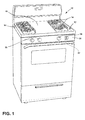
- reference numeral 10 generally defines a range having a cooktop 12 with a plurality of gas burner units 14 arrayed about a top surface 16 of the cooktop 12, with knobs 18 to control the gas burner units 14.
- the present disclosure is relevant for use with any gas burner units 14, whether located on a stand-alone hob, or a cooktop 12 associated with a range 10.
- the knobs 18 are located on a front edge 20 of the cooktop 12, and a general primary air inlet 22 (also called an alternate primary air inlet herein) is provided behind one or more of the knobs 18.
- the alternate primary air inlet 22 allows ambient air from the front of the cooktop 12 to enter the space below the cooktop 24 ( FIG.
- Primary air which enters the area 24 below the cooktop 12 supplies any of the plurality of gas burner units 14 with primary air.
- the alternate primary air inlets 22 may be positioned below knobs 18 on a top surface 16 of the cooktop 12. In such embodiments, the alternate primary air inlets 22 allow the inlet of primary air into the area 24 below the cooktop 12 in a location remote from the gas burner units 14, where the primary air is available to any of the plurality of gas burner units 14.
- the gas burner unit 14 includes a spreader 30 and a burner cap 32 located above the top surface 16 of the cooktop 12.
- the spreader 30 includes a plurality of gas outlets 34, which are enclosed by the burner cap 32 and a venturi mixing chamber 36 (shown in FIGS. 7-8 ) in fluid connection with the plurality of gas outlets 34.
- An orifice holder 40 is positioned at least partially below the cooktop 12, and operates to mechanically secure various elements of the gas burner unit 14 in physical alignment with each other and the cooktop 12, including at least the spreader 30, a gas orifice 40, and a spark electrode 42.
- the orifice holder 38 includes a main body portion 44, a flange 46 extending outwardly from the main body 44, a spark electrode locating arm 48 extending outwardly from the main body 44, a central cylindrical portion 50 extending upwardly from the main body 44, and a plurality of protrusions 52 extending upwardly from the main body 44, as further described below.
- the orifice holder 38 can be fabricated from a variety of suitable materials, such as brass, aluminum, cast iron, ceramics, heat-resistant plastics, or any other material capable of withstanding the temperatures resulting from burner operation for an extended period of time and over numerous thermal cycles.
- the orifice holder 38 is affixed to the cooktop 12 by screwing a plurality of screws 60 through screw holes 62 in the cooktop 12 and into receiving holes 64 in the flange 46 extending outwardly from a top edge 66 of the main body 44 of the orifice holder 38.
- the main body 44 of the orifice holder 38 mechanically secures the gas orifice 40 in position, and locates the orifice 40 centrally within the gas burner unit 14 to direct gas upwardly into the venturi mixing chamber 36 defined by the spreader 30.
- the orifice 40 optionally includes threads which are screwed into a threaded receiving portion of the orifice holder 38 to maintain the orifice 40 in the desired position and orientation.
- Other fittings between the orifice holder 38 and the orifice 40 such as mechanical engagement, friction fit, suitable adhesives, or any other fittings capable of maintaining the position of the orifice 40 through the temperatures and pressures generally encountered by orifice holders 38 and orifices 40 may be used to secure the orifice 40 in the orifice holder 38.
- the central cylindrical portion 50 extends upwardly from the main body 44 and the flange 46 through an opening 67 in the cooktop 12 to mechanically engage the spreader 30.
- Asymmetrical locating grooves 68 are provided in the central cylindrical portion 50 to engage corresponding alignment tabs 70 on the spreader 30.
- the asymmetrical fitting between the orifice holder 38 and the spreader 30 ensures that the spreader 30 and venturi 36 are coaxially aligned with the gas orifice 40.
- the main body 44 is in fluid connection with the spreader 30 through a bore 72 in the central cylindrical portion 50 of the orifice holder 38, allowing gas to flow from the orifice 40 into the venturi mixing chamber 36.
- the orifice holder 38 includes a gas inlet 74, fluidly connecting a gas supply line (not shown) with the gas orifice 40.
- the orifice holder 38 mechanically secures the spark electrode 42 in position with respect to the cooktop 12 and the spreader 30.
- the spark locating arm 48 extends axially outwardly from the main body 44 of the orifice holder 38 with an aperture 80 therethrough to receive the spark electrode 42.
- the spark electrode 42 extends upwardly through a spark electrode hole 82 in the cooktop 12 and into a receiving portion 84 of the spreader 30.
- the orifice holder also includes a plurality of protrusions 52 extending upwardly from the flange 46, which define a plurality of upwardly directed primary air inlets 90 which extend through the opening 67 in the cooktop 12.
- the plurality of primary air inlets 90 are in fluid communication with the venturi mixing chamber 36, and permit the supply of ambient air from above the top surface 16 of the cooktop 12 to the venturi mixing chamber 36 to act as primary air which mixes with the fuel gas to form a fuel-rich mixture of gas and primary air for ignition.
- the protrusions 52 preferably extend above the top surface 16 of the cooktop 12, thereby creating a barrier to the entrance of liquids or other spilled materials on the cooktop 12 from entering the upwardly directed primary air inlets 90.
- the protrusions 52 extend about 3.8 mm above the flange 46, resulting in a protrusion of approximately 2.9 mm above the top surface 16 of the cooktop 12.
- the cross sectional area of the primary air inlets 90 is preferably greater than about 63 mm 2 to allow primary air to enter the venturi 36 at the desired pressure and speed.
- the size of the primary air inlets 90 can be increased beyond 63 mm 2 , but the size and arrangement of the primary air inlets are preferably maintained so that the primary air inlets 90 are located on the area of the cooktop 12 covered by the spreader 30, to maintain the aesthetic of the cooktop 12 and to prevent spilled materials from entering the cooktop 12 by having the spreader 30 shield the primary air inlets 90.
- the spreader 30 is preferably separated from the top surface 16 of the cooktop 12 by at least about 2 mm to allow air flow from the top surface 16 of the cooktop 12 to the primary air inlet 90.
- the upwardly directed primary air inlets 90 are positioned in close proximity to the venturi 36, and are physically associated with a particular gas burner unit 14, to provide primary air primarily to that particular gas burner unit 14. These upwardly directed primary air inlets 90 associated with each gas burner unit 14 prevent pressure drops of the primary air that can otherwise occur when multiple gas burner units 14 on the cooktop 12 are used simultaneously. The upwardly directed primary air inlets 90 also assist the gas burner unit 14 to operate at a low simmer rate during sudden changes in pressure, such as those experienced when an oven door is opened during operation of the gas burner unit 14 at a simmer rate. In the embodiment depicted in FIGS. 2-8 , the upwardly directed primary air inlets 90 are immediately adjacent the central cylindrical portion 50 of the orifice holder 38. However, in alternate embodiments, the primary air inlets 90 could be separated from the central cylindrical portion 50, and could extend through additional openings in the cooktop 12.
- the main body 44 of the orifice holder 38 has openings 92, allowing primary air from the general primary air inlet 22 to enter the main body 44 of the orifice holder 38, which is in fluid communication with the venturi mixing chamber 36.
- This open main body 44 design allows primary air to enter the venturi mixing chamber 36 from both a general primary air inlet 22 (supplying air to the area 24 below the cooktop 12 to reach multiple gas burner units 14) and the upwardly directed primary air inlets 90 specifically associated with the particular gas burner unit 14.
- ambient air from above the top surface 16 of the cooktop 12 is drawn underneath the spreader 30 and into the upwardly directed primary air inlets 90.
- the upwardly directed primary air inlets 90 are in fluid communication with the venturi mixing chamber 36, through the main body 44 of the orifice holder 38.
- the flow of gas through the orifice 40 and into the venturi 36 creates a vacuum effect to pull in the ambient air through the upwardly directed primary air inlets 90 and into the venturi 36.
- the venturi 36 the ambient air is mixed with the gas prior to combustion, creating a fuel-rich mixture.
- the fuel-rich mixture then flows outwardly through the gas outlets 34 of the spreader 30. When the fuel-rich mixture exits the gas outlets 34, it is ignited by the spark electrode 42, resulting in burner flames.
- the orifice holder 38 includes a gas inlet 74, which receives a gas supply line (not shown) and which provides a fluid connection from the gas supply line to the orifice 40.
- the orifice 40 is coaxially aligned with the venturi mixing chamber 36 to direct gas upwardly into the venturi chamber 36.
- the present disclosure includes a gas burner unit 14 for a cooktop 12 having a spreader 30 positioned above the top surface 16 of the cooktop 12.
- the spreader 30 has gas outlets 34.
- a venturi 36 is in fluid communication with the gas outlets 34.
- An orifice holder 38 having a plurality of protrusions 52 defining a plurality of upwardly directed primary air inlets 90.
- the plurality of upwardly directed primary air inlets 90 are in fluid communication with the venturi 36.
- the present disclosure includes a cooktop 12 having at least one gas burner unit 14, with a plurality of primary air inlets 90 extending through a top surface 16 of the cooktop 12.
- the plurality of primary air inlets 90 are in fluid communication with a venturi 36 to provide ambient air from above the cooktop 12 to the venturi 36.
- a ridge formed by the protrusions 52 extends upwardly about the edge of each primary air inlet 90.
- the present disclosure includes a cooktop 12 having a plurality of gas burner units 14 including a first gas burner unit 14.
- a first primary air inlet 22 is located remotely from the gas burner units 14, which allows the ingress of ambient air to an area 24 below the cooktop 12 to supply primary air to the plurality of gas burner units 14.
- a second primary air inlet 90 is associated with one of the plurality of gas burner units 14. The second primary air inlet 90 allows ingress of ambient air from above a top surface 16 of the cooktop 12 to supply primary air to the first gas burner unit 14, wherein the second primary air inlet 90 is directed upwardly through the top surface 16 of the cooktop 12.
- the orifice holder 38 for the gas burner unit 14 described herein performs three functions: (1) it aligns components of the gas supply system including the gas inlet 74, orifice 40, venturi 36 and gas outlets 34; (2) it prevents spillage of food, liquids, or other materials into the primary air inlets 90; and (3) it provides additional primary air access to improve the combustion of gas during operation of the gas burner unit 14.
Landscapes
- Engineering & Computer Science (AREA)
- Chemical & Material Sciences (AREA)
- Combustion & Propulsion (AREA)
- Mechanical Engineering (AREA)
- General Engineering & Computer Science (AREA)
- Gas Burners (AREA)
Abstract
Description
- The present disclosure relates generally to primary air inlets to supply primary air to a gas burner to facilitate combustion of fuel gas supplied to the burner. Traditional gas burners for cooktops and stoves obtain the primary air either above or below the cooktop. The primary air is mixed with the fuel gas prior to ignition of the gas to form a fuel-rich mixture for ignition. The remaining air required for complete combustion is obtained from the ambient air in the room following ignition, and is referred to herein as secondary air.
- Thus, the burners will compete for primary air resulting in longer flame and incomplete combustion. Therefore, a need exists in the gas burner art to provide simple and efficient solutions for supplying adequate air to the burner.
- The present disclosure provides a way for supplying additional primary air into the venturi and help to reduce the pressure drop into the burner box caused by the orifice flows when multiple burners are in operation. Additionally, the present disclosure demonstrates a burner that improves the burner performance and simmer rate.
- The present disclosure provides solutions to supply the adequate primary air to the venturi. One aspect of the disclosure includes a gas burner including two half circular holes in the body of an orifice holder to provide additional access to the primary air close to the venturi and at least one protrusion to prevent the spillage of liquid food into the orifice along with a locating mechanism attached to the spreader base in order to achieve the correct alignment between the orifice holder and the venturi.
- One aspect of the present disclosure includes a gas burner unit for a cooktop having a spreader positioned above the top surface of the cooktop. The spreader has a plurality of gas outlets. A venturi is in fluid communication with the gas outlets. An orifice holder has a plurality of protrusions defining a plurality of upwardly directed primary air inlets. The plurality of primary air inlets are in fluid communication with the venturi.
- In another aspect, the present disclosure includes a cooktop having at least one gas burner unit, with a plurality of primary air inlets extending through a top surface of the cooktop. The plurality of primary air inlets are in fluid communication with a venturi to provide ambient air from above the cooktop to the venturi. A ridge extends upwardly about the edge of each primary air inlet.
- In another aspect, the present disclosure includes a cooktop having a plurality of gas burner units including a first gas burner unit. A first primary air inlet is located remotely from the gas burner units, which allows the ingress of ambient air to an area below the cooktop to supply primary air to the plurality of gas burner units. A second primary air inlet is associated with one of the plurality of gas burner units. The second primary air inlet allows ingress of ambient air from above a top surface of the cooktop to supply primary air to the first gas burner unit, wherein the second primary air inlet is directed upwardly through the top surface of the cooktop.
- These and other features, advantages, and objects of the present device will be further understood and appreciated by those skilled in the art upon studying the following specification, claims, and appended drawings.
-
-
FIG. 1 is a top perspective view of a range with gas burner units according to the present disclosure; -
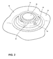
FIG. 2 is a top perspective view of a gas burner unit according to the present disclosure; -
FIG. 3 is a top perspective partially exploded view of the gas burner unit shown inFIG. 2 ; -
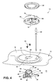
FIG. 4 is a top perspective exploded view of the gas burner unit shown inFIG. 2 ; -
FIG. 5 is a side elevation view of the gas burner unit shown inFIG. 2 ; -
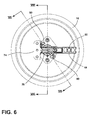
FIG. 6 is a bottom plan view of the gas burner shown inFIG. 2 ; -
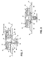
FIG. 7 is a cross sectional view of the gas burner shown inFIG. 2 , taken along the line VII-VII inFIG. 6 ; and -
FIG. 8 is a cross sectional view of the gas burner shown inFIG. 2 taken along the line VIII-VIII inFIG. 6 . - With reference to the embodiment generally illustrated in
FIG. 1 ,reference numeral 10 generally defines a range having acooktop 12 with a plurality ofgas burner units 14 arrayed about atop surface 16 of thecooktop 12, withknobs 18 to control thegas burner units 14. The present disclosure is relevant for use with anygas burner units 14, whether located on a stand-alone hob, or acooktop 12 associated with arange 10. Theknobs 18 are located on afront edge 20 of thecooktop 12, and a general primary air inlet 22 (also called an alternate primary air inlet herein) is provided behind one or more of theknobs 18. The alternateprimary air inlet 22 allows ambient air from the front of thecooktop 12 to enter the space below the cooktop 24 (FIG. 5 ), where certain components of thegas burner unit 14 are located, as further described below. Primary air which enters thearea 24 below thecooktop 12 supplies any of the plurality ofgas burner units 14 with primary air. In other embodiments, the alternateprimary air inlets 22 may be positioned belowknobs 18 on atop surface 16 of thecooktop 12. In such embodiments, the alternateprimary air inlets 22 allow the inlet of primary air into thearea 24 below thecooktop 12 in a location remote from thegas burner units 14, where the primary air is available to any of the plurality ofgas burner units 14. - As shown in the embodiment depicted in
FIGS. 2-8 , thegas burner unit 14 includes aspreader 30 and aburner cap 32 located above thetop surface 16 of thecooktop 12. Thespreader 30 includes a plurality ofgas outlets 34, which are enclosed by theburner cap 32 and a venturi mixing chamber 36 (shown inFIGS. 7-8 ) in fluid connection with the plurality ofgas outlets 34. Anorifice holder 40 is positioned at least partially below thecooktop 12, and operates to mechanically secure various elements of thegas burner unit 14 in physical alignment with each other and thecooktop 12, including at least thespreader 30, agas orifice 40, and aspark electrode 42. Theorifice holder 38 includes amain body portion 44, aflange 46 extending outwardly from themain body 44, a sparkelectrode locating arm 48 extending outwardly from themain body 44, a centralcylindrical portion 50 extending upwardly from themain body 44, and a plurality ofprotrusions 52 extending upwardly from themain body 44, as further described below. Theorifice holder 38 can be fabricated from a variety of suitable materials, such as brass, aluminum, cast iron, ceramics, heat-resistant plastics, or any other material capable of withstanding the temperatures resulting from burner operation for an extended period of time and over numerous thermal cycles. - As best shown in the embodiment illustrated in
FIGS. 3 ,4 , and8 , theorifice holder 38 is affixed to thecooktop 12 by screwing a plurality ofscrews 60 throughscrew holes 62 in thecooktop 12 and into receivingholes 64 in theflange 46 extending outwardly from atop edge 66 of themain body 44 of theorifice holder 38. As shown inFIG. 4 , themain body 44 of theorifice holder 38 mechanically secures thegas orifice 40 in position, and locates theorifice 40 centrally within thegas burner unit 14 to direct gas upwardly into theventuri mixing chamber 36 defined by thespreader 30. Theorifice 40 optionally includes threads which are screwed into a threaded receiving portion of theorifice holder 38 to maintain theorifice 40 in the desired position and orientation. Other fittings between theorifice holder 38 and theorifice 40, such as mechanical engagement, friction fit, suitable adhesives, or any other fittings capable of maintaining the position of theorifice 40 through the temperatures and pressures generally encountered byorifice holders 38 andorifices 40 may be used to secure theorifice 40 in theorifice holder 38. The centralcylindrical portion 50 extends upwardly from themain body 44 and theflange 46 through anopening 67 in thecooktop 12 to mechanically engage thespreader 30. Asymmetrical locatinggrooves 68 are provided in the centralcylindrical portion 50 to engagecorresponding alignment tabs 70 on thespreader 30. The asymmetrical fitting between theorifice holder 38 and thespreader 30 ensures that thespreader 30 andventuri 36 are coaxially aligned with thegas orifice 40. Themain body 44 is in fluid connection with thespreader 30 through abore 72 in the centralcylindrical portion 50 of theorifice holder 38, allowing gas to flow from theorifice 40 into theventuri mixing chamber 36. Also, as shown inFIG. 8 , theorifice holder 38 includes agas inlet 74, fluidly connecting a gas supply line (not shown) with thegas orifice 40. - Also as shown in
FIG. 4 , theorifice holder 38 mechanically secures thespark electrode 42 in position with respect to thecooktop 12 and thespreader 30. Thespark locating arm 48 extends axially outwardly from themain body 44 of theorifice holder 38 with anaperture 80 therethrough to receive thespark electrode 42. Thespark electrode 42 extends upwardly through aspark electrode hole 82 in thecooktop 12 and into a receivingportion 84 of thespreader 30. - As shown in
FIGS. 3-4 , the orifice holder also includes a plurality ofprotrusions 52 extending upwardly from theflange 46, which define a plurality of upwardly directedprimary air inlets 90 which extend through theopening 67 in thecooktop 12. The plurality ofprimary air inlets 90 are in fluid communication with theventuri mixing chamber 36, and permit the supply of ambient air from above thetop surface 16 of thecooktop 12 to theventuri mixing chamber 36 to act as primary air which mixes with the fuel gas to form a fuel-rich mixture of gas and primary air for ignition. Theprotrusions 52 preferably extend above thetop surface 16 of thecooktop 12, thereby creating a barrier to the entrance of liquids or other spilled materials on thecooktop 12 from entering the upwardly directedprimary air inlets 90. In the embodiment depicted inFIGS. 3-4 , theprotrusions 52 extend about 3.8 mm above theflange 46, resulting in a protrusion of approximately 2.9 mm above thetop surface 16 of thecooktop 12. - The cross sectional area of the
primary air inlets 90 is preferably greater than about 63 mm2 to allow primary air to enter theventuri 36 at the desired pressure and speed. The size of theprimary air inlets 90 can be increased beyond 63 mm2, but the size and arrangement of the primary air inlets are preferably maintained so that theprimary air inlets 90 are located on the area of thecooktop 12 covered by thespreader 30, to maintain the aesthetic of thecooktop 12 and to prevent spilled materials from entering thecooktop 12 by having thespreader 30 shield theprimary air inlets 90. Additionally, thespreader 30 is preferably separated from thetop surface 16 of thecooktop 12 by at least about 2 mm to allow air flow from thetop surface 16 of thecooktop 12 to theprimary air inlet 90. - The upwardly directed
primary air inlets 90 are positioned in close proximity to theventuri 36, and are physically associated with a particulargas burner unit 14, to provide primary air primarily to that particulargas burner unit 14. These upwardly directedprimary air inlets 90 associated with eachgas burner unit 14 prevent pressure drops of the primary air that can otherwise occur when multiplegas burner units 14 on thecooktop 12 are used simultaneously. The upwardly directedprimary air inlets 90 also assist thegas burner unit 14 to operate at a low simmer rate during sudden changes in pressure, such as those experienced when an oven door is opened during operation of thegas burner unit 14 at a simmer rate. In the embodiment depicted inFIGS. 2-8 , the upwardly directedprimary air inlets 90 are immediately adjacent the centralcylindrical portion 50 of theorifice holder 38. However, in alternate embodiments, theprimary air inlets 90 could be separated from the centralcylindrical portion 50, and could extend through additional openings in thecooktop 12. - As shown in
FIG. 5 , themain body 44 of theorifice holder 38 hasopenings 92, allowing primary air from the generalprimary air inlet 22 to enter themain body 44 of theorifice holder 38, which is in fluid communication with theventuri mixing chamber 36. This openmain body 44 design allows primary air to enter theventuri mixing chamber 36 from both a general primary air inlet 22 (supplying air to thearea 24 below thecooktop 12 to reach multiple gas burner units 14) and the upwardly directedprimary air inlets 90 specifically associated with the particulargas burner unit 14. - As shown in the embodiment depicted in
FIGS. 6-7 , ambient air from above thetop surface 16 of thecooktop 12 is drawn underneath thespreader 30 and into the upwardly directedprimary air inlets 90. The upwardly directedprimary air inlets 90 are in fluid communication with theventuri mixing chamber 36, through themain body 44 of theorifice holder 38. The flow of gas through theorifice 40 and into theventuri 36 creates a vacuum effect to pull in the ambient air through the upwardly directedprimary air inlets 90 and into theventuri 36. In theventuri 36, the ambient air is mixed with the gas prior to combustion, creating a fuel-rich mixture. The fuel-rich mixture then flows outwardly through thegas outlets 34 of thespreader 30. When the fuel-rich mixture exits thegas outlets 34, it is ignited by thespark electrode 42, resulting in burner flames. - As shown in
FIG. 8 in greater detail, theorifice holder 38 includes agas inlet 74, which receives a gas supply line (not shown) and which provides a fluid connection from the gas supply line to theorifice 40. Theorifice 40 is coaxially aligned with theventuri mixing chamber 36 to direct gas upwardly into theventuri chamber 36. - In one aspect, the present disclosure includes a
gas burner unit 14 for acooktop 12 having aspreader 30 positioned above thetop surface 16 of thecooktop 12. Thespreader 30 hasgas outlets 34. Aventuri 36 is in fluid communication with thegas outlets 34. Anorifice holder 38 having a plurality ofprotrusions 52 defining a plurality of upwardly directedprimary air inlets 90. The plurality of upwardly directedprimary air inlets 90 are in fluid communication with theventuri 36. - In another aspect, the present disclosure includes a
cooktop 12 having at least onegas burner unit 14, with a plurality ofprimary air inlets 90 extending through atop surface 16 of thecooktop 12. The plurality ofprimary air inlets 90 are in fluid communication with aventuri 36 to provide ambient air from above thecooktop 12 to theventuri 36. A ridge formed by theprotrusions 52 extends upwardly about the edge of eachprimary air inlet 90. - In another aspect, the present disclosure includes a
cooktop 12 having a plurality ofgas burner units 14 including a firstgas burner unit 14. A firstprimary air inlet 22 is located remotely from thegas burner units 14, which allows the ingress of ambient air to anarea 24 below thecooktop 12 to supply primary air to the plurality ofgas burner units 14. A secondprimary air inlet 90 is associated with one of the plurality ofgas burner units 14. The secondprimary air inlet 90 allows ingress of ambient air from above atop surface 16 of thecooktop 12 to supply primary air to the firstgas burner unit 14, wherein the secondprimary air inlet 90 is directed upwardly through thetop surface 16 of thecooktop 12. - The
orifice holder 38 for thegas burner unit 14 described herein performs three functions: (1) it aligns components of the gas supply system including thegas inlet 74,orifice 40,venturi 36 andgas outlets 34; (2) it prevents spillage of food, liquids, or other materials into theprimary air inlets 90; and (3) it provides additional primary air access to improve the combustion of gas during operation of thegas burner unit 14.
Claims (15)
- A gas burner unit (14) for a cooktop (12), comprising:a spreader (30) positioned above a top surface (16) of the cooktop (12), the spreader (30) having a plurality of gas outlets (34);a venturi (36) in fluid communication with the gas outlets (34); andan orifice holder (38) having a plurality of protrusions (52) defining a plurality of upwardly directed primary air inlets (90), wherein the plurality of upwardly directed primary air inlets (90) are in fluid communication with the venturi (36).
- The gas burner unit (14) of claim 1, wherein each of the upwardly directed primary air inlets (90) has a semi-circular shape.
- The gas burner unit (14) of any one of claims 1-2, having two upwardly directed primary air inlets (90).
- The gas burner unit (14) of any one of claims 1-3, wherein the spreader (30) is secured to the orifice holder (38) using a groove (68) and alignment tab (70) to maintain the desired coaxial alignment between the spreader (30) and the orifice holder (38).
- The gas burner unit (14) of any one of claims 1-4, wherein the upwardly directed primary air inlets (90) have a total cross sectional area of about (63) mm2 or greater.
- The gas burner unit (14) of any one of claims 1-5, wherein the orifice holder (38) has a main body portion (44) in which a gas orifice (40) is mechanically secured in coaxial alignment with the venturi (36), and wherein the main body portion (44) is in fluid connection with the venturi (36).
- The gas burner unit (14) of any one of claims 1-6, wherein the plurality of protrusions (52) extend above the top surface (16) of the cooktop (12).
- The gas burner unit (14) of any one of claims 1-7, wherein the protrusions (52) extend about 2.9 mm above the top surface (16) of the cooktop (12).
- The gas burner unit (14) of any one of claims 1-8, wherein the spreader (30) is separated from the top surface (16) of the cooktop (12) by at least about 2 mm to form a path for ambient air to flow from above the cooktop (12) to the plurality of upwardly directed primary air inlets (90).
- The gas burner unit (14) of any one of claims 1-9, further comprising:a plurality of alternate primary air inlets (22) that are in fluid communication with ambient air and in fluid communication with an area below the cooktop (12); anda main body portion (44) of the orifice holder (38), wherein the main body portion (44) has openings (92) which permit fluid communication between the main body portion (44) and the area below the cooktop (12).
- The gas burner unit (14) of claim 10, wherein the plurality of alternate primary air inlets (22) intake ambient air from a location remote from the gas burner unit (14) and supply it to the area under the cooktop (12), and wherein the area under the cooktop (12) is in fluid connection with the venturi (36).
- The gas burner unit (14) of any one of claims 10-11, wherein the plurality of alternate primary air inlets (22) supply the gas burner unit (14) and additional gas burner units (14) located on the cooktop (12).
- The gas burner unit (14) of any one of claims 1-12, wherein each of the plurality of upwardly directed primary air inlets (90) is adjacent the venturi (36).
- The gas burner unit (14) of any one of claims 1-13, wherein the orifice holder (38) is aluminum or brass.
- The gas burner unit (14) of any one of claims 1-14, wherein the venturi (36) is defined by the spreader (30).
Applications Claiming Priority (1)
| Application Number | Priority Date | Filing Date | Title |
|---|---|---|---|
| US14/102,864 US9513012B2 (en) | 2013-12-11 | 2013-12-11 | Additional primary air access for surface gas burners |
Publications (3)
| Publication Number | Publication Date |
|---|---|
| EP2884176A2 true EP2884176A2 (en) | 2015-06-17 |
| EP2884176A3 EP2884176A3 (en) | 2015-08-12 |
| EP2884176B1 EP2884176B1 (en) | 2018-11-14 |
Family
ID=52023297
Family Applications (1)
| Application Number | Title | Priority Date | Filing Date |
|---|---|---|---|
| EP14197194.5A Active EP2884176B1 (en) | 2013-12-11 | 2014-12-10 | Cooktop with gas burner having additional primary air supply |
Country Status (3)
| Country | Link |
|---|---|
| US (3) | US9513012B2 (en) |
| EP (1) | EP2884176B1 (en) |
| BR (1) | BR102014031013A2 (en) |
Cited By (2)
| Publication number | Priority date | Publication date | Assignee | Title |
|---|---|---|---|---|
| WO2020193302A1 (en) * | 2019-03-25 | 2020-10-01 | BSH Hausgeräte GmbH | Gas hob |
| EP3809041A1 (en) * | 2019-10-18 | 2021-04-21 | Whirlpool Corporation | Gas cooktop burner assembly |
Families Citing this family (13)
| Publication number | Priority date | Publication date | Assignee | Title |
|---|---|---|---|---|
| US20150198336A1 (en) * | 2014-01-10 | 2015-07-16 | Jürgen Koch | Gas orifice holder |
| ES2875035T3 (en) | 2015-11-26 | 2021-11-08 | Electrolux Appliances AB | Gas burner and hob comprising a gas burner |
| US10222069B2 (en) * | 2016-07-19 | 2019-03-05 | Whirlpool Corporation | Sliding orifice holder for a gas powered cooktop |
| USD821802S1 (en) * | 2016-11-03 | 2018-07-03 | Samsung Electronics Co., Ltd. | Gas range |
| US10697641B2 (en) * | 2016-12-19 | 2020-06-30 | Whirlpool Corporation | Orifice holder mounting system for gas cooktop |
| US10551056B2 (en) * | 2017-02-23 | 2020-02-04 | Whirlpool Corporation | Burner base |
| ES2697724B2 (en) | 2017-07-26 | 2021-05-14 | Copreci S Coop | Gas burner assembly for a gas cooking appliance, and gas cooking appliance incorporating said gas burner assembly |
| US10823402B2 (en) * | 2017-08-09 | 2020-11-03 | Haier Us Appliance Solutions, Inc. | Gas burner assembly for a cooktop appliance |
| ES2702783A1 (en) * | 2017-09-05 | 2019-03-05 | Bsh Electrodomesticos Espana Sa | Gas cooking point and gas cooker. (Machine-translation by Google Translate, not legally binding) |
| US11359818B2 (en) * | 2018-12-07 | 2022-06-14 | Electrolux Home Products, Inc. | Gas burner |
| EP3980690B1 (en) * | 2019-07-10 | 2025-01-01 | Femas Metal San. Ve Tic. A.S. | A burner assembly with radial outward flame |
| US11421890B2 (en) | 2020-12-08 | 2022-08-23 | Whirlpool Corporation | Burner cap for a burner assembly |
| US11940148B2 (en) | 2021-10-28 | 2024-03-26 | Electrolux Appliances Aktiebolag | Multi injection dual ring gas burner for domestic gas cooking units |
Family Cites Families (16)
| Publication number | Priority date | Publication date | Assignee | Title |
|---|---|---|---|---|
| DE19505469C1 (en) | 1995-02-17 | 1996-02-08 | Schott Glaswerke | Arrangement for feed of primary air to atmospheric gas burner via glass ceramic cooking plate |
| US6299436B1 (en) | 1997-10-20 | 2001-10-09 | Bsh Home Appliances Corporation | Plurality fingered burner |
| US6589046B2 (en) * | 2001-08-21 | 2003-07-08 | Uwe Harneit | Gas burner for outdoor cooking |
| FR2831242B1 (en) | 2001-10-24 | 2004-01-16 | Sourdillon Sa | ATMOSPHERIC TYPE GAS BURNER |
| MY147945A (en) | 2004-02-02 | 2013-02-15 | Electrolux Ab | Gas burner |
| ITVE20040031A1 (en) | 2004-07-09 | 2004-10-09 | Ohg Defendi S R L | MULTI-FLAME SECTOR BURNER. |
| US7291009B2 (en) | 2004-09-08 | 2007-11-06 | General Electric Company | Dual stacked gas burner and a venturi for improving burner operation |
| ITMC20050036A1 (en) | 2005-04-29 | 2006-10-30 | So M I Press Societa Metalli Iniettati Spa | DOUBLE BURNER FOR GAS COOKERS, WITH MULTIPLE CONCENTRIC FLAME CHAINS, HIGH POWER. |
| FR2889293B1 (en) | 2005-07-29 | 2009-12-18 | Burner Systems Int Bsi | MULTI-CROWN GAS BURNER WITH CONCENTRIC FLAME |
| US7661954B2 (en) | 2005-09-13 | 2010-02-16 | Uwe Harneit | Gas burner |
| US8302593B2 (en) | 2005-12-30 | 2012-11-06 | General Electric Company | Gas burner assembly including inner and outer burners and methods for implementing same |
| ITTO20070133A1 (en) | 2007-02-26 | 2008-08-27 | Indesit Co Spa | GAS BURNER SYSTEM FOR FOOD COOKING APPLIANCES |
| TR200901741A2 (en) | 2009-03-06 | 2009-08-21 | Turaş Gaz Armatürleri̇ Sanayi̇ Ve Ti̇caret Anoni̇m Şi̇rketi̇ | Multiple gas burner for furnaces. |
| US20100279238A1 (en) | 2009-05-02 | 2010-11-04 | Uwe Harneit | Gas burner |
| US8845326B2 (en) | 2010-10-13 | 2014-09-30 | General Electric Company | Gas burner assembly |
| US9347670B2 (en) * | 2012-05-21 | 2016-05-24 | Paul Bryan Cadima | Burner assembly for an appliance |
-
2013
- 2013-12-11 US US14/102,864 patent/US9513012B2/en active Active
-
2014
- 2014-12-10 EP EP14197194.5A patent/EP2884176B1/en active Active
- 2014-12-11 BR BR102014031013A patent/BR102014031013A2/en not_active Application Discontinuation
-
2016
- 2016-10-25 US US15/333,465 patent/US10228128B2/en active Active
-
2019
- 2019-01-18 US US16/251,861 patent/US11098891B2/en active Active
Non-Patent Citations (1)
| Title |
|---|
| None |
Cited By (2)
| Publication number | Priority date | Publication date | Assignee | Title |
|---|---|---|---|---|
| WO2020193302A1 (en) * | 2019-03-25 | 2020-10-01 | BSH Hausgeräte GmbH | Gas hob |
| EP3809041A1 (en) * | 2019-10-18 | 2021-04-21 | Whirlpool Corporation | Gas cooktop burner assembly |
Also Published As
| Publication number | Publication date |
|---|---|
| EP2884176B1 (en) | 2018-11-14 |
| US10228128B2 (en) | 2019-03-12 |
| EP2884176A3 (en) | 2015-08-12 |
| US11098891B2 (en) | 2021-08-24 |
| US20170038061A1 (en) | 2017-02-09 |
| BR102014031013A2 (en) | 2016-10-25 |
| US20190154253A1 (en) | 2019-05-23 |
| US9513012B2 (en) | 2016-12-06 |
| US20150159880A1 (en) | 2015-06-11 |
Similar Documents
| Publication | Publication Date | Title |
|---|---|---|
| EP2884176B1 (en) | Cooktop with gas burner having additional primary air supply | |
| CN104713087B (en) | Bottom cup lid and burner and gas appliance | |
| CN104713084B (en) | burner and gas appliance | |
| EP1838997B1 (en) | Gas burner for cooking appliances | |
| WO2016141644A1 (en) | Burner and fuel gas implement | |
| WO2009078647A2 (en) | A top-burner and cooker comprising the same | |
| WO2014127727A1 (en) | Air-blowing full, pre-mixed integrated stove | |
| US10551057B2 (en) | Gas burner with multiple rings of flames having two parallel venturis, one above the other | |
| US10393386B2 (en) | System of gas burners, in particular for a cooking top for household use | |
| CN104713083A (en) | Burner and gas appliance | |
| US20200191387A1 (en) | Gas burner for cooking appliances | |
| JP2011220653A (en) | Burner for gas cooking stove, and gas cooking stove | |
| US20060147865A1 (en) | Cooking range burner head assembly | |
| CN205191567U (en) | A completely updraft burner | |
| CN110088529A (en) | Gas burner and kitchen range including gas burner | |
| US11371697B2 (en) | Gas burner, gas burner assembly and domestic cooking appliance | |
| CN112240549A (en) | Completely upper air inlet type burner | |
| CN206291208U (en) | An easy-to-clean high-power stove burner | |
| KR200476819Y1 (en) | Portable high-fired torch lamp | |
| CN113551230B (en) | An ignition device, a stove burner and a stove | |
| BR112018010689B1 (en) | GAS BURNER AND COOKING STOVE | |
| CN215175065U (en) | Fire distributor and gas burner using same | |
| CN204534579U (en) | Burners and Gas Appliances | |
| CN210861204U (en) | Integrated kitchen of going up air inlet formula combustor and applied this combustor completely | |
| CN211372404U (en) | Completely upper air inlet type burner |
Legal Events
| Date | Code | Title | Description |
|---|---|---|---|
| PUAI | Public reference made under article 153(3) epc to a published international application that has entered the european phase |
Free format text: ORIGINAL CODE: 0009012 |
|
| 17P | Request for examination filed |
Effective date: 20141210 |
|
| AK | Designated contracting states |
Kind code of ref document: A2 Designated state(s): AL AT BE BG CH CY CZ DE DK EE ES FI FR GB GR HR HU IE IS IT LI LT LU LV MC MK MT NL NO PL PT RO RS SE SI SK SM TR |
|
| AX | Request for extension of the european patent |
Extension state: BA ME |
|
| PUAL | Search report despatched |
Free format text: ORIGINAL CODE: 0009013 |
|
| AK | Designated contracting states |
Kind code of ref document: A3 Designated state(s): AL AT BE BG CH CY CZ DE DK EE ES FI FR GB GR HR HU IE IS IT LI LT LU LV MC MK MT NL NO PL PT RO RS SE SI SK SM TR |
|
| AX | Request for extension of the european patent |
Extension state: BA ME |
|
| RIC1 | Information provided on ipc code assigned before grant |
Ipc: F23D 14/06 20060101AFI20150709BHEP Ipc: F23L 1/00 20060101ALI20150709BHEP Ipc: F24C 3/08 20060101ALI20150709BHEP |
|
| R17P | Request for examination filed (corrected) |
Effective date: 20160209 |
|
| RBV | Designated contracting states (corrected) |
Designated state(s): AL AT BE BG CH CY CZ DE DK EE ES FI FR GB GR HR HU IE IS IT LI LT LU LV MC MK MT NL NO PL PT RO RS SE SI SK SM TR |
|
| STAA | Information on the status of an ep patent application or granted ep patent |
Free format text: STATUS: EXAMINATION IS IN PROGRESS |
|
| 17Q | First examination report despatched |
Effective date: 20171010 |
|
| GRAP | Despatch of communication of intention to grant a patent |
Free format text: ORIGINAL CODE: EPIDOSNIGR1 |
|
| STAA | Information on the status of an ep patent application or granted ep patent |
Free format text: STATUS: GRANT OF PATENT IS INTENDED |
|
| INTG | Intention to grant announced |
Effective date: 20180903 |
|
| GRAS | Grant fee paid |
Free format text: ORIGINAL CODE: EPIDOSNIGR3 |
|
| GRAA | (expected) grant |
Free format text: ORIGINAL CODE: 0009210 |
|
| STAA | Information on the status of an ep patent application or granted ep patent |
Free format text: STATUS: THE PATENT HAS BEEN GRANTED |
|
| AK | Designated contracting states |
Kind code of ref document: B1 Designated state(s): AL AT BE BG CH CY CZ DE DK EE ES FI FR GB GR HR HU IE IS IT LI LT LU LV MC MK MT NL NO PL PT RO RS SE SI SK SM TR |
|
| REG | Reference to a national code |
Ref country code: CH Ref legal event code: EP Ref country code: AT Ref legal event code: REF Ref document number: 1065265 Country of ref document: AT Kind code of ref document: T Effective date: 20181115 |
|
| REG | Reference to a national code |
Ref country code: DE Ref legal event code: R096 Ref document number: 602014035928 Country of ref document: DE |
|
| REG | Reference to a national code |
Ref country code: IE Ref legal event code: FG4D |
|
| REG | Reference to a national code |
Ref country code: NL Ref legal event code: MP Effective date: 20181114 |
|
| REG | Reference to a national code |
Ref country code: LT Ref legal event code: MG4D |
|
| REG | Reference to a national code |
Ref country code: AT Ref legal event code: MK05 Ref document number: 1065265 Country of ref document: AT Kind code of ref document: T Effective date: 20181114 |
|
| PG25 | Lapsed in a contracting state [announced via postgrant information from national office to epo] |
Ref country code: BG Free format text: LAPSE BECAUSE OF FAILURE TO SUBMIT A TRANSLATION OF THE DESCRIPTION OR TO PAY THE FEE WITHIN THE PRESCRIBED TIME-LIMIT Effective date: 20190214 Ref country code: FI Free format text: LAPSE BECAUSE OF FAILURE TO SUBMIT A TRANSLATION OF THE DESCRIPTION OR TO PAY THE FEE WITHIN THE PRESCRIBED TIME-LIMIT Effective date: 20181114 Ref country code: LV Free format text: LAPSE BECAUSE OF FAILURE TO SUBMIT A TRANSLATION OF THE DESCRIPTION OR TO PAY THE FEE WITHIN THE PRESCRIBED TIME-LIMIT Effective date: 20181114 Ref country code: AT Free format text: LAPSE BECAUSE OF FAILURE TO SUBMIT A TRANSLATION OF THE DESCRIPTION OR TO PAY THE FEE WITHIN THE PRESCRIBED TIME-LIMIT Effective date: 20181114 Ref country code: ES Free format text: LAPSE BECAUSE OF FAILURE TO SUBMIT A TRANSLATION OF THE DESCRIPTION OR TO PAY THE FEE WITHIN THE PRESCRIBED TIME-LIMIT Effective date: 20181114 Ref country code: HR Free format text: LAPSE BECAUSE OF FAILURE TO SUBMIT A TRANSLATION OF THE DESCRIPTION OR TO PAY THE FEE WITHIN THE PRESCRIBED TIME-LIMIT Effective date: 20181114 Ref country code: NO Free format text: LAPSE BECAUSE OF FAILURE TO SUBMIT A TRANSLATION OF THE DESCRIPTION OR TO PAY THE FEE WITHIN THE PRESCRIBED TIME-LIMIT Effective date: 20190214 Ref country code: LT Free format text: LAPSE BECAUSE OF FAILURE TO SUBMIT A TRANSLATION OF THE DESCRIPTION OR TO PAY THE FEE WITHIN THE PRESCRIBED TIME-LIMIT Effective date: 20181114 Ref country code: IS Free format text: LAPSE BECAUSE OF FAILURE TO SUBMIT A TRANSLATION OF THE DESCRIPTION OR TO PAY THE FEE WITHIN THE PRESCRIBED TIME-LIMIT Effective date: 20190314 |
|
| PG25 | Lapsed in a contracting state [announced via postgrant information from national office to epo] |
Ref country code: PT Free format text: LAPSE BECAUSE OF FAILURE TO SUBMIT A TRANSLATION OF THE DESCRIPTION OR TO PAY THE FEE WITHIN THE PRESCRIBED TIME-LIMIT Effective date: 20190314 Ref country code: NL Free format text: LAPSE BECAUSE OF FAILURE TO SUBMIT A TRANSLATION OF THE DESCRIPTION OR TO PAY THE FEE WITHIN THE PRESCRIBED TIME-LIMIT Effective date: 20181114 Ref country code: GR Free format text: LAPSE BECAUSE OF FAILURE TO SUBMIT A TRANSLATION OF THE DESCRIPTION OR TO PAY THE FEE WITHIN THE PRESCRIBED TIME-LIMIT Effective date: 20190215 Ref country code: RS Free format text: LAPSE BECAUSE OF FAILURE TO SUBMIT A TRANSLATION OF THE DESCRIPTION OR TO PAY THE FEE WITHIN THE PRESCRIBED TIME-LIMIT Effective date: 20181114 Ref country code: AL Free format text: LAPSE BECAUSE OF FAILURE TO SUBMIT A TRANSLATION OF THE DESCRIPTION OR TO PAY THE FEE WITHIN THE PRESCRIBED TIME-LIMIT Effective date: 20181114 Ref country code: SE Free format text: LAPSE BECAUSE OF FAILURE TO SUBMIT A TRANSLATION OF THE DESCRIPTION OR TO PAY THE FEE WITHIN THE PRESCRIBED TIME-LIMIT Effective date: 20181114 |
|
| PG25 | Lapsed in a contracting state [announced via postgrant information from national office to epo] |
Ref country code: CZ Free format text: LAPSE BECAUSE OF FAILURE TO SUBMIT A TRANSLATION OF THE DESCRIPTION OR TO PAY THE FEE WITHIN THE PRESCRIBED TIME-LIMIT Effective date: 20181114 Ref country code: DK Free format text: LAPSE BECAUSE OF FAILURE TO SUBMIT A TRANSLATION OF THE DESCRIPTION OR TO PAY THE FEE WITHIN THE PRESCRIBED TIME-LIMIT Effective date: 20181114 Ref country code: PL Free format text: LAPSE BECAUSE OF FAILURE TO SUBMIT A TRANSLATION OF THE DESCRIPTION OR TO PAY THE FEE WITHIN THE PRESCRIBED TIME-LIMIT Effective date: 20181114 |
|
| REG | Reference to a national code |
Ref country code: CH Ref legal event code: PL |
|
| REG | Reference to a national code |
Ref country code: DE Ref legal event code: R097 Ref document number: 602014035928 Country of ref document: DE |
|
| PG25 | Lapsed in a contracting state [announced via postgrant information from national office to epo] |
Ref country code: SM Free format text: LAPSE BECAUSE OF FAILURE TO SUBMIT A TRANSLATION OF THE DESCRIPTION OR TO PAY THE FEE WITHIN THE PRESCRIBED TIME-LIMIT Effective date: 20181114 Ref country code: EE Free format text: LAPSE BECAUSE OF FAILURE TO SUBMIT A TRANSLATION OF THE DESCRIPTION OR TO PAY THE FEE WITHIN THE PRESCRIBED TIME-LIMIT Effective date: 20181114 Ref country code: MC Free format text: LAPSE BECAUSE OF FAILURE TO SUBMIT A TRANSLATION OF THE DESCRIPTION OR TO PAY THE FEE WITHIN THE PRESCRIBED TIME-LIMIT Effective date: 20181114 Ref country code: LU Free format text: LAPSE BECAUSE OF NON-PAYMENT OF DUE FEES Effective date: 20181210 Ref country code: SK Free format text: LAPSE BECAUSE OF FAILURE TO SUBMIT A TRANSLATION OF THE DESCRIPTION OR TO PAY THE FEE WITHIN THE PRESCRIBED TIME-LIMIT Effective date: 20181114 Ref country code: RO Free format text: LAPSE BECAUSE OF FAILURE TO SUBMIT A TRANSLATION OF THE DESCRIPTION OR TO PAY THE FEE WITHIN THE PRESCRIBED TIME-LIMIT Effective date: 20181114 |
|
| REG | Reference to a national code |
Ref country code: IE Ref legal event code: MM4A |
|
| PLBE | No opposition filed within time limit |
Free format text: ORIGINAL CODE: 0009261 |
|
| STAA | Information on the status of an ep patent application or granted ep patent |
Free format text: STATUS: NO OPPOSITION FILED WITHIN TIME LIMIT |
|
| REG | Reference to a national code |
Ref country code: BE Ref legal event code: MM Effective date: 20181231 |
|
| 26N | No opposition filed |
Effective date: 20190815 |
|
| PG25 | Lapsed in a contracting state [announced via postgrant information from national office to epo] |
Ref country code: SI Free format text: LAPSE BECAUSE OF FAILURE TO SUBMIT A TRANSLATION OF THE DESCRIPTION OR TO PAY THE FEE WITHIN THE PRESCRIBED TIME-LIMIT Effective date: 20181114 Ref country code: IE Free format text: LAPSE BECAUSE OF NON-PAYMENT OF DUE FEES Effective date: 20181210 |
|
| PG25 | Lapsed in a contracting state [announced via postgrant information from national office to epo] |
Ref country code: BE Free format text: LAPSE BECAUSE OF NON-PAYMENT OF DUE FEES Effective date: 20181231 |
|
| PG25 | Lapsed in a contracting state [announced via postgrant information from national office to epo] |
Ref country code: CH Free format text: LAPSE BECAUSE OF NON-PAYMENT OF DUE FEES Effective date: 20181231 Ref country code: LI Free format text: LAPSE BECAUSE OF NON-PAYMENT OF DUE FEES Effective date: 20181231 |
|
| PG25 | Lapsed in a contracting state [announced via postgrant information from national office to epo] |
Ref country code: MT Free format text: LAPSE BECAUSE OF NON-PAYMENT OF DUE FEES Effective date: 20181210 |
|
| PG25 | Lapsed in a contracting state [announced via postgrant information from national office to epo] |
Ref country code: TR Free format text: LAPSE BECAUSE OF FAILURE TO SUBMIT A TRANSLATION OF THE DESCRIPTION OR TO PAY THE FEE WITHIN THE PRESCRIBED TIME-LIMIT Effective date: 20181114 |
|
| PG25 | Lapsed in a contracting state [announced via postgrant information from national office to epo] |
Ref country code: MK Free format text: LAPSE BECAUSE OF NON-PAYMENT OF DUE FEES Effective date: 20181114 Ref country code: CY Free format text: LAPSE BECAUSE OF FAILURE TO SUBMIT A TRANSLATION OF THE DESCRIPTION OR TO PAY THE FEE WITHIN THE PRESCRIBED TIME-LIMIT Effective date: 20181114 Ref country code: HU Free format text: LAPSE BECAUSE OF FAILURE TO SUBMIT A TRANSLATION OF THE DESCRIPTION OR TO PAY THE FEE WITHIN THE PRESCRIBED TIME-LIMIT; INVALID AB INITIO Effective date: 20141210 |
|
| P01 | Opt-out of the competence of the unified patent court (upc) registered |
Effective date: 20230522 |
|
| PGFP | Annual fee paid to national office [announced via postgrant information from national office to epo] |
Ref country code: GB Payment date: 20241217 Year of fee payment: 11 |
|
| PGFP | Annual fee paid to national office [announced via postgrant information from national office to epo] |
Ref country code: FR Payment date: 20241227 Year of fee payment: 11 |
|
| PGFP | Annual fee paid to national office [announced via postgrant information from national office to epo] |
Ref country code: IT Payment date: 20241121 Year of fee payment: 11 |
|
| PGFP | Annual fee paid to national office [announced via postgrant information from national office to epo] |
Ref country code: DE Payment date: 20241227 Year of fee payment: 11 |