EP2884127A1 - Radial roller bearing cage - Google Patents
Radial roller bearing cage Download PDFInfo
- Publication number
- EP2884127A1 EP2884127A1 EP12879154.8A EP12879154A EP2884127A1 EP 2884127 A1 EP2884127 A1 EP 2884127A1 EP 12879154 A EP12879154 A EP 12879154A EP 2884127 A1 EP2884127 A1 EP 2884127A1
- Authority
- EP
- European Patent Office
- Prior art keywords
- axial direction
- fitting
- sections
- section
- cage
- Prior art date
- Legal status (The legal status is an assumption and is not a legal conclusion. Google has not performed a legal analysis and makes no representation as to the accuracy of the status listed.)
- Granted
Links
Images





Classifications
-
- F—MECHANICAL ENGINEERING; LIGHTING; HEATING; WEAPONS; BLASTING
- F16—ENGINEERING ELEMENTS AND UNITS; GENERAL MEASURES FOR PRODUCING AND MAINTAINING EFFECTIVE FUNCTIONING OF MACHINES OR INSTALLATIONS; THERMAL INSULATION IN GENERAL
- F16C—SHAFTS; FLEXIBLE SHAFTS; ELEMENTS OR CRANKSHAFT MECHANISMS; ROTARY BODIES OTHER THAN GEARING ELEMENTS; BEARINGS
- F16C33/00—Parts of bearings; Special methods for making bearings or parts thereof
- F16C33/30—Parts of ball or roller bearings
- F16C33/46—Cages for rollers or needles
- F16C33/4694—Single-split roller or needle cages
-
- F—MECHANICAL ENGINEERING; LIGHTING; HEATING; WEAPONS; BLASTING
- F16—ENGINEERING ELEMENTS AND UNITS; GENERAL MEASURES FOR PRODUCING AND MAINTAINING EFFECTIVE FUNCTIONING OF MACHINES OR INSTALLATIONS; THERMAL INSULATION IN GENERAL
- F16C—SHAFTS; FLEXIBLE SHAFTS; ELEMENTS OR CRANKSHAFT MECHANISMS; ROTARY BODIES OTHER THAN GEARING ELEMENTS; BEARINGS
- F16C19/00—Bearings with rolling contact, for exclusively rotary movement
- F16C19/22—Bearings with rolling contact, for exclusively rotary movement with bearing rollers essentially of the same size in one or more circular rows, e.g. needle bearings
- F16C19/24—Bearings with rolling contact, for exclusively rotary movement with bearing rollers essentially of the same size in one or more circular rows, e.g. needle bearings for radial load mainly
- F16C19/26—Bearings with rolling contact, for exclusively rotary movement with bearing rollers essentially of the same size in one or more circular rows, e.g. needle bearings for radial load mainly with a single row of rollers
-
- F—MECHANICAL ENGINEERING; LIGHTING; HEATING; WEAPONS; BLASTING
- F16—ENGINEERING ELEMENTS AND UNITS; GENERAL MEASURES FOR PRODUCING AND MAINTAINING EFFECTIVE FUNCTIONING OF MACHINES OR INSTALLATIONS; THERMAL INSULATION IN GENERAL
- F16C—SHAFTS; FLEXIBLE SHAFTS; ELEMENTS OR CRANKSHAFT MECHANISMS; ROTARY BODIES OTHER THAN GEARING ELEMENTS; BEARINGS
- F16C33/00—Parts of bearings; Special methods for making bearings or parts thereof
- F16C33/30—Parts of ball or roller bearings
- F16C33/46—Cages for rollers or needles
-
- F—MECHANICAL ENGINEERING; LIGHTING; HEATING; WEAPONS; BLASTING
- F16—ENGINEERING ELEMENTS AND UNITS; GENERAL MEASURES FOR PRODUCING AND MAINTAINING EFFECTIVE FUNCTIONING OF MACHINES OR INSTALLATIONS; THERMAL INSULATION IN GENERAL
- F16C—SHAFTS; FLEXIBLE SHAFTS; ELEMENTS OR CRANKSHAFT MECHANISMS; ROTARY BODIES OTHER THAN GEARING ELEMENTS; BEARINGS
- F16C33/00—Parts of bearings; Special methods for making bearings or parts thereof
- F16C33/30—Parts of ball or roller bearings
- F16C33/46—Cages for rollers or needles
- F16C33/4617—Massive or moulded cages having cage pockets surrounding the rollers, e.g. machined window cages
-
- F—MECHANICAL ENGINEERING; LIGHTING; HEATING; WEAPONS; BLASTING
- F16—ENGINEERING ELEMENTS AND UNITS; GENERAL MEASURES FOR PRODUCING AND MAINTAINING EFFECTIVE FUNCTIONING OF MACHINES OR INSTALLATIONS; THERMAL INSULATION IN GENERAL
- F16C—SHAFTS; FLEXIBLE SHAFTS; ELEMENTS OR CRANKSHAFT MECHANISMS; ROTARY BODIES OTHER THAN GEARING ELEMENTS; BEARINGS
- F16C33/00—Parts of bearings; Special methods for making bearings or parts thereof
- F16C33/30—Parts of ball or roller bearings
- F16C33/46—Cages for rollers or needles
- F16C33/4617—Massive or moulded cages having cage pockets surrounding the rollers, e.g. machined window cages
- F16C33/4623—Massive or moulded cages having cage pockets surrounding the rollers, e.g. machined window cages formed as one-piece cages, i.e. monoblock cages
- F16C33/4635—Massive or moulded cages having cage pockets surrounding the rollers, e.g. machined window cages formed as one-piece cages, i.e. monoblock cages made from plastic, e.g. injection moulded window cages
-
- F—MECHANICAL ENGINEERING; LIGHTING; HEATING; WEAPONS; BLASTING
- F16—ENGINEERING ELEMENTS AND UNITS; GENERAL MEASURES FOR PRODUCING AND MAINTAINING EFFECTIVE FUNCTIONING OF MACHINES OR INSTALLATIONS; THERMAL INSULATION IN GENERAL
- F16C—SHAFTS; FLEXIBLE SHAFTS; ELEMENTS OR CRANKSHAFT MECHANISMS; ROTARY BODIES OTHER THAN GEARING ELEMENTS; BEARINGS
- F16C33/00—Parts of bearings; Special methods for making bearings or parts thereof
- F16C33/30—Parts of ball or roller bearings
- F16C33/46—Cages for rollers or needles
- F16C33/467—Details of individual pockets, e.g. shape or roller retaining means
- F16C33/4676—Details of individual pockets, e.g. shape or roller retaining means of the stays separating adjacent cage pockets, e.g. guide means for the bearing-surface of the rollers
-
- F—MECHANICAL ENGINEERING; LIGHTING; HEATING; WEAPONS; BLASTING
- F16—ENGINEERING ELEMENTS AND UNITS; GENERAL MEASURES FOR PRODUCING AND MAINTAINING EFFECTIVE FUNCTIONING OF MACHINES OR INSTALLATIONS; THERMAL INSULATION IN GENERAL
- F16C—SHAFTS; FLEXIBLE SHAFTS; ELEMENTS OR CRANKSHAFT MECHANISMS; ROTARY BODIES OTHER THAN GEARING ELEMENTS; BEARINGS
- F16C19/00—Bearings with rolling contact, for exclusively rotary movement
- F16C19/22—Bearings with rolling contact, for exclusively rotary movement with bearing rollers essentially of the same size in one or more circular rows, e.g. needle bearings
- F16C19/44—Needle bearings
- F16C19/46—Needle bearings with one row or needles
- F16C19/463—Needle bearings with one row or needles consisting of needle rollers held in a cage, i.e. subunit without race rings
-
- F—MECHANICAL ENGINEERING; LIGHTING; HEATING; WEAPONS; BLASTING
- F16—ENGINEERING ELEMENTS AND UNITS; GENERAL MEASURES FOR PRODUCING AND MAINTAINING EFFECTIVE FUNCTIONING OF MACHINES OR INSTALLATIONS; THERMAL INSULATION IN GENERAL
- F16C—SHAFTS; FLEXIBLE SHAFTS; ELEMENTS OR CRANKSHAFT MECHANISMS; ROTARY BODIES OTHER THAN GEARING ELEMENTS; BEARINGS
- F16C2226/00—Joining parts; Fastening; Assembling or mounting parts
- F16C2226/50—Positive connections
- F16C2226/70—Positive connections with complementary interlocking parts
-
- F—MECHANICAL ENGINEERING; LIGHTING; HEATING; WEAPONS; BLASTING
- F16—ENGINEERING ELEMENTS AND UNITS; GENERAL MEASURES FOR PRODUCING AND MAINTAINING EFFECTIVE FUNCTIONING OF MACHINES OR INSTALLATIONS; THERMAL INSULATION IN GENERAL
- F16C—SHAFTS; FLEXIBLE SHAFTS; ELEMENTS OR CRANKSHAFT MECHANISMS; ROTARY BODIES OTHER THAN GEARING ELEMENTS; BEARINGS
- F16C2226/00—Joining parts; Fastening; Assembling or mounting parts
- F16C2226/50—Positive connections
- F16C2226/70—Positive connections with complementary interlocking parts
- F16C2226/76—Positive connections with complementary interlocking parts with tongue and groove or key and slot
Definitions
- the present invention relates to a cage for a radial roller bearing that is made of synthetic resin and that has a non-continuous section in one location in the circumferential direction.
- radial roller bearings such as the radial roller bearing 1 illustrated in FIG. 23 are assembled in portions where large radial loads are applied.
- This radial roller bearing 1 is constructed such that a plurality of rollers 6 that are provided between a cylindrical shaped outer-ring raceway 3, which is formed around the inner circumferential surface of an outer-diameter side member 2, and a cylindrical shaped inner-ring raceway 5, which is formed around the outer circumferential surface of a shaft 4 that is located on the inner-diameter side, are supported by a cage 7 so as to be able to roll freely.
- combinations of an outer-diameter side member 2 and shaft 4 there is a combination of a housing, which does not rotate even during operation, and a rotating shaft, and a combination of a gear or roller, which rotates during operation, and a support shaft thereof.
- radial needle bearings that use needles are also included as a radial roller bearing.
- the cage 7 is completely constructed into a cylindrical shape using a synthetic resin material.
- the cage 7 has a pair of circular ring shaped rim sections 8 that are arranged concentric with each other and separated from each other in the axial direction, and has a plurality of column sections 9 that are arranged intermittently in the circumferential direction and span between the rim sections 8.
- the portions that are surrounded on four sides by adjacent column sections 9 in the circumferential direction and the rim sections 8 form pockets 10 for supporting the rollers 6 so as to be able to roll freely.
- this kind of cage 7 is provided between the inner circumferential surface of the outer-diameter side member 2 and the outer circumferential surface of the shaft 4 so as to be able to rotate relative to the outer-diameter side member 2 and shaft 4.
- This cage 7 rotates with respect to the outer-diameter side member 2 and shaft 4 together with the revolving motion of the rollers 6.
- the cage 7 When assembling the radial roller bearing 1, in order to arrange the cage 7 around the inner-ring raceway 5, the cage 7 is inserted from the end section of the shaft 4, and moved in the axial direction until it surrounds the inner-ring raceway 5.
- an obstacle such as an outward-facing flange section or the like that has an outer diameter dimension that is greater than the inner diameter dimension of the cage 7 in the middle portion in the axial direction between the end section of the shaft 4 and the inner-ring raceway 5
- this obstacle is in the way, and it may not be possible to move the cage 7 to a position surrounding the inner-ring raceway 5.
- FIG. 25 illustrates the cage 7a that is disclosed in GB 1,352,909 (A ).
- This cage 7a is made of a synthetic resin and has a non-continuous section 11 at one location in the circumferential direction.
- the end sections 12a, 12b that are separated by this non-continuous section 11 fit together with an uneven fit by way of fitting sections 13.
- an outer-diameter side fitting piece 14a, 14b and inner-diameter side fitting pieces 15a, 15b that form fitting sections 13 is formed on each of the end sections 12a, 12b. More specifically, of one end section 12a, an outer-diameter side fitting piece 14a is formed on one half section in the axial direction of the outer-diameter side half section, and an inner-diameter side fitting piece 15a is formed on the other half section in the axial direction of the inner-diameter side half section.
- an outer-diameter side fitting piece 14b is formed on the other half section in the axial direction of the outer-diameter side half section
- an inner-diameter side fitting piece 15b is formed on the one half section in the axial direction of the inner-diameter side half section.
- Concave sections 16a, 16b are formed in the circumferential surface of the pair of rim sections 8a, 8b. More specifically, on the outer circumferential surface of one rim section 8a, concave sections 16a that are recessed inward in the radial direction are formed at portions that are aligned in the axial direction with the pockets 10, and on the inner circumferential surface of the other rim section 8b, concave sections 16b that are recessed outward in the radial direction are formed at portions that are aligned in the axial direction with the pockets 10.
- This kind of cage 7a is formed by so-called axial draw molding in which synthetic resin is injected inside the cavity of an axial draw mold (mold tool) that is formed by a pair of split molds (mold tool elements), after which these split molds are separated in the axial direction. Therefore, when compared with the case of using radial draw molding, in which the mold is a complex mold which comprises a pair of mold elements that move in the axial direction and a plurality of mold elements that move in the radial direction, the manufacturing cost of the cage 7a is kept low in the axial draw molding.
- This axial draw molding is performed by moving a pair of split molds in the axial direction, so when removing the split molds, it is possible to prevent damage such as plastic deformation or bleaching from occurring in the stopper sections that are provided on the edge sections of the openings of the pockets for preventing the rollers from dropping out. Therefore, axial draw molding is preferably used in cases where the volume of the stopper sections is so large that so-called unreasonable removal work in which the mold elements are removed to the outer-diameter side by pressing and elastically expanding the stopper sections is difficult, or in cases where column sections are arranged in portion further on the outside in the radial direction than the pitch circle diameter of the rollers such that it is difficult to remove the mold elements to the outside in the radial direction.
- the cage 7a can be assembled by elastically expanding cage 7a enough to ride over the obstacle, and moving the cage 7a in the axial direction to where it surrounds the shaft 4.
- the end sections 12a, 12b that are both sides of the non-continuous section 11 fit together by way of the fitting sections 13 not only so that there is not relative displacement in the axial direction, but also so that there is no relative displacement in the radial direction. Therefore, during operation of the radial roller bearing, expansion of the diameter of the cage due to centrifugal force is prevented.
- the outer-diameter side fitting pieces 14a, 14b and the inner-diameter side fitting pieces 15b, 15a are pressed in the radial direction, so it becomes easy for wear of these outer-diameter side fitting pieces 14a, 14b and inner-diameter side fitting pieces 15b, 15a to advance, and in the worst case, there is a possibility the pieces might break.
- the related literature above is incorporated in this specification by reference.
- the object of the present invention is to achieve construction of a cage for a radial roller bearing that can be manufactured by axial draw molding, and so that the end sections on both sides of the non-continuous section can fit together such that relative displacement in the radial direction is possible, and that relative displacement in the axial direction is not possible.
- the cage for a radial roller bearing of the present invention that is made into a single piece by injection molding using an axial draw mold having a pair of split molds, and has: a pair of rim sections, a plurality of column sections, a plurality of pockets and a fitting section, and is provided with a non-continuous section at one location in the circumferential direction.
- the pair of rim sections are incomplete ring shaped, and are provided concentric to each other with a space between them in the axial direction.
- concave sections that are recessed in the radial direction are formed at positions that are aligned in the axial direction with the pockets.
- the formation locations of these concave sections are opposite in the radial direction on both sides in the axial direction of the pockets.
- the fitting section is such that the end sections that are provided on both sides of the non-continuous section fit together.
- the fitting section has an inside fitting piece that is provided on one of the end sections, and a pair of outside fitting pieces that are provided on the other end section.
- the inside fitting piece is provided in the middle section in the axial direction of the one end section, and extends in the circumferential direction toward the other end section.
- the pair of outside fitting pieces are provided in separated portions on both sides in the axial direction of the other end section, extend in the circumferential direction toward the one end section, and do not overlap each other with respect to the axial direction (when seen from the axial direction). In other words, these outside fitting pieces are such that the formation positions in the radial direction are offset from each other.
- the inside fitting piece is placed in the portion between the outside fitting pieces (with respect to the axial direction).
- the inside fitting piece and the outside fitting pieces fit together in the axial direction without the inside fitting piece and the outside fitting pieces overlapping each other in the radial direction.
- the inside fitting piece when forming the cut away sections on the inside fitting piece, by making the pair of cut away section continuous in the radial direction, the inside fitting piece can comprise a pair of inside fitting elements that are separated in the axial direction.
- the outside fitting pieces can comprise a plurality of (two or more) outside fitting thin plates that are separated in the radial direction.
- the cage for a radial roller bearing of the present invention has a pair of rim sections, a plurality of column sections, a plurality of pockets, a non-continuous section that is provided at one location in the circumferential direction, and a fitting section where end sections on both sides of the non-continuous section fit together; and this fitting section comprises at least a pair of outside fitting pieces that are provided at two separated locations in the axial direction of one of the end sections, and extend in the circumferential direction toward the other end section, the widths in the radial direction being less than the width in the radial direction of the end section, and that do not overlap with each other with respect to the axial direction, and at least one inside fitting sections that is located on the other end section in the portion in the axial direction between the outside fitting sections, and fits with the outside fitting sections without overlapping the outside fitting sections in the radial direction.
- construction of a cage for a radial roller bearing is achieved wherein together with it being possible to manufacture the cage by axial draw molding, end sections that are provided on both sides of a non-continuous section fit together so that relative displacement in the radial direction is possible, and so that relative displacement in the axial direction is not possible.
- a fitting section where the end sections on both sides of a non-continuous section fit together comprises an inside fitting piece that is provided on one end section, and a pair of outside fitting pieces that are provided on the other end section, in which the inside fitting piece is located in the portion between the outside fitting pieces, and this inside fitting piece and the outside fitting pieces fit together only in the axial direction without overlapping each other in the radial direction. Therefore, the fitting section is such that the end sections fit together so that relative displacement is possible in the radial direction, and so that relative displacement is not possible in the axial direction.
- the present invention during operation the inside fitting piece and the outside fitting pieces of the fitting section are not pressed in the radial direction, and thus together with no damage, such as wear, occurring to the inside fitting piece and outside fitting pieces, it is possible for the diameter of the cage for a radial roller bearing to expand due to the action of centrifugal force. Moreover, the force required for causing relative displacement in the circumferential direction of the end sections is small, so it is possible for the non-continuous section to smoothly expand or contract. As a result, when assembled in a radial roller bearing that is assembled in a manual transmission or the like, it is possible to effectively prevent fretting wear from occurring.
- the structure in which the pair of outside fitting pieces do not overlap each other with regard to the axial direction gives the possibility to pull out in the axial direction portions of the split molds that were provided for forming a space for the inside fitting piece during the production process thereof, and the concave sections are formed in the rim sections so as to pull out in the axial direction portions of the split molds that were provided for forming pockets.
- the pair of split molds are regulated to shapes so as to be able to be removed in the axial direction after injection molding without damaging the cage, so the cage for a radial roller bearing of the present invention can be manufactured using axial draw molding.
- the inside fitting piece so as to comprise a pair of inside fitting elements that are separated in the axial direction, it is possible to greatly reduce the volume of the inside fitting piece. Therefore, it is possible to reduce the weight and material cost of the cage for a radial roller bearing to an even higher degree.
- the outside fitting pieces comprise a plurality of outside fitting thin plates that are separated in the radial direction
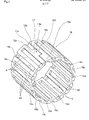
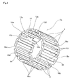
- FIG. 1 to FIG. 4 illustrate a first example of an embodiment of the present invention.
- the cage 7b for a radial roller (needle) bearing of this example comprises a pair of rim sections 8c, 8d, which have an incomplete ring shape and that are arranged concentric with each other having a space in the axial direction between them, and a plurality of column sections 9 that are provided intermittently in the circumferential direction and span between the rim sections 8c, 8d.
- the portions that are surrounded on four sides by column sections 9 that are adjacent in the circumferential direction, and the rim sections 8c, 8d function as pockets 10 that hold rollers 6 (refer to FIG. 23 ) so as to be able to roll freely.
- concave sections 16c that are recessed inward in the radial direction and concave sections 16d that are recessed outward in the radial direction are provided so as to alternate in the circumferential direction and so as to differ with each other between the rim sections 8c, 8d.
- concave sections 16c and concave sections 16d which are formed in opposite directions in the radial direction, are arranged one by one in the portions on both sides in the axial direction of the pockets 10.
- the width dimension in the circumferential direction of these concave sections 16c, 16d is the same as the width direction in the circumferential direction of the pockets 10, and the depth dimension in the radial direction is 1/2 the thickness dimension in the radial direction of the rim sections 8c, 8d.
- a non-continuous section 11a is provided at one location in the circumferential direction of the cage 7b.
- the end sections 12c, 12d (column sections 9) that are on both sides of this non-continuous section 11a fit with each other by way of a fitting section 13a.
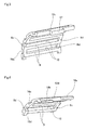
- an inside fitting piece 17 is formed in the middle section (center section) in the axial direction of one end section 12c of these end sections 12c, 12d so as to extend in the circumferential direction toward the other end section 12d.
- a pair of outside fitting pieces 18a, 18b are formed in separated portions on both sides in the axial direction of the other end section 12d so as to extend in the circumferential direction toward the one end section 12c.
- the inside fitting piece 17 and outside fitting pieces 18a, 18b are all rectangular plate shaped (partial cylindrical shaped). Moreover, the dimension in the axial direction of the inside fitting piece 17 is the same as dimension in the axial direction of the outside fitting pieces 18a, 18b. In other words, the dimension in the axial direction of the inside fitting piece 17 and outside fitting pieces 18a, 18b is 1/3 the dimension in the axial direction of the end sections 12a, 12b (over all width).
- the dimension in the radial direction of the inside fitting piece 17 is the same as the dimension in the radial direction of the one end section 12c, and the dimension in the radial direction of the outside fitting pieces 18a, 18b is about 1/2 (at least no more than 1/2) the dimension in the radial direction of the other end section 12d.
- one of the outside fitting pieces 18a is provided on one end section in the axial direction of the outer-diameter side half section of the other end section 12d
- the other outside fitting piece 18b is provided on the other end section in the axial direction of the inner-diameter side half section of the other end section 12d. In this way, the outside fitting pieces 18a, 18b do not overlap each other with regard to the axial direction.
- construction is such that the surfaces on both side in the radial direction of the outside fitting pieces 18a, 18b are parallel with each other, however, a tapered surfaces are possible where the inside surface in the radial direction of the outside fitting piece 18a that is provided on the outer-diameter side half section of the end section 12d and the outside surface in the radial direction of the outside fitting piece 18b that is provided on the inner-diameter side half section of the end section 12d can be inclined in a direction such that the dimension in the radial direction of the outside fitting pieces 18a, 18b becomes smaller going from the center side in the axial direction of the cage 7b toward the end sides in the axial direction (rim sections 8a, 8b).
- the inside fitting piece 17 is located in the portion between the outside fitting pieces 18a, 18b as illustrated in FIG. 1 and FIG. 2 .
- both side surfaces in the axial direction of the inside fitting piece 17 closely face the other side surface (side surface on the left side in FIG. 4 ) in the axial direction of the outside fitting piece 18a and the one side surface (side surface on the right side in FIG. 4 ) of the outside fitting piece 18b.
- the cage 7b of this example having this kind of construction, can be manufacturing using axial draw molding, and during use, the end sections 12c, 12d that are located on both side of the non-continuous section 11a can be fitted together so that relative displacement in the radial direction is possible, and so that relative displacement in the axial direction is not possible.
- fitting section 13a comprises an inside fitting piece 17 that is provided on one end section 12c, and a pair of outside fitting pieces 18a, 18b that are provided on the other end section 12d, and by placing the inside fitting piece 17 in the portion between the outside fitting pieces 18a, 18b, the inside fitting piece 17 and the outside fitting pieces 18a, 18b fit together only in the axial direction without overlapping in the radial direction. Therefore, the fitting section 13a is such that the end sections 12c, 12d fit together so that relative displacement in the radial direction is possible, and so that relative displacement in the axial direction is not possible.
- the cage 7b of this example is constructed so that the outside fitting pieces 18a, 18b do not overlap with regard to the axial direction, or in other words, the formation locations of these pieces in the radial direction are shifted from each other, so of the split molds of the axial draw mold, the portion that is provided for forming a space (portion between the outside fitting pieces 18a, 18b) for the inside fitting piece 17 can be pulled out in the axial direction without interference with the outside fitting pieces 18a, 18b.
- concave sections 16c that are recessed inward in the radial direction, and concave sections 16d that are recessed outward in the radial direction are formed so as to alternate in the circumferential direction in the portions that are aligned in the axial direction with the pockets 10, so the portion of the split molds that are provided for forming the pockets 10 can be pulled out in the axial direction without interference with the rim sections 8c, 8d.
- the cage 7b of this example is regulated to a shape such that a pair of split molds can be separated in the axial direction without damaging the cage after injection molding, so the cage 7b can be manufactured using axial draw molding.
- the cage of this example can be manufactured such that injection molding using synthetic resin is performed in the same was as in the case of a typical synthetic resin cage in which polyamide resin, polyphenylene sulfide resin, or these resins mixed with reinforcement fibers is injected into the cavity of an axial draw mold (mold tool) having a pair of split molds (not illustrated in the figure), after which the split molds are pulled out and removed in the axial direction.
- the cage 7b of this example can be manufactured using axial draw molding that is able to keep manufacturing costs low, and the end sections 12c, 12d on both sides of the non-continuous section 11a can fit together so that relative displacement in the radial direction is possible, and so that relative displacement in the axial direction is not possible.
- the cage 7b of this example is manufactured using axial draw molding, so in the state immediately after the pair of split molds are pulled out in the axial direction, the end sections 12c, 12d are still not fitted together and there is a gap between these end sections 12c, 12d.
- the diameter of the cage contracts, so as illustrated in the figure, the end sections 12c, 12d fit together.
- the cage 7b is manufactured using synthetic resin and has high elasticity, so after assembly it is elastically deformed by opposing members and put into the desired shape.
- FIG. 5 and FIG. 6 illustrate a second example of an embodiment of the present invention.
- the positions where the outside fitting pieces 18a, 18b of the fitting section 13b are formed differ from in the construction of the first example of an embodiment. More specifically, the positions in the radial direction of the pair of outside fitting pieces 18a, 18b that are provided on the other end section 12d are opposite from the case in the first example, where the outside fitting piece 18a is formed on one end section in the axial direction of the inner-diameter side half section of the end section 12d, and the outside fitting piece 18b is formed on the other end section in the axial direction of the outer-diameter side half section of the end section 12d. In this example as well, these outside fitting pieces 18a, 18b do not overlap each other with regard to the axial direction.
- the cage 7c of this example can be manufacturing using axial draw molding, and the end sections 12c, 12d that are provided on both sides of the non-continuous section 11a can be fitted together by way of the fitting section 13b so that relative displacement in the radial direction is possible and so that relative displacement in the axial direction is not possible.
- the other construction, functions and effects of this example are the same as in the first example of an embodiment.
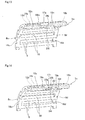
- FIG. 7 illustrates a third example of an embodiment of the present invention.
- the shape of the inside fitting piece 17a of the fitting section 13c is devised so that after injection molding, transformation such as shrunken depressions or curves in the inside fitting piece 17 is prevented.
- cut away sections 19a, 19b having a rectangular shape are formed in portions on both sides in the axial direction of the inside fitting piece 17a, which reduces the dimension in the radial direction of the inside fitting piece 17a in these portions on both sides in the axial direction. More specifically, together with forming a cut away section 19a in a portion on the inner-diameter side of one side in the axial direction (left side in FIG.
- a cut away section 19b is formed in a portion on the outer-diameter side of the other side in the axial direction (right side in FIG. 7 ) of the inside fitting piece 17a.
- the inside fitting piece 17a of this example in which these kinds of cut away sections 19a, 19b are formed has a crankshaft shaped cross-sectional shape. These cut away sections 19a, 19b are formed at the same time as injection molding.
- the outside fitting piece 18a that is formed on the outer-diameter side half section of the other end section 12d is located on one side in the axial direction of the inside fitting piece 17a
- the outside fitting piece 18b that is formed on the inner-diameter side half section of the other end section 12d is located on the other side in the axial direction of the inside fitting piece 17a.
- the inside fitting piece 17a and the outside fitting pieces 18a, 18b do no overlap in the radial direction.
- the volume of the inside fitting piece 17a can be reduced, so after injection molding, it becomes difficult for shrinkage depressions to occur in the inside fitting piece.
- FIG. 8 illustrates a fourth example of an embodiment of the present invention.
- rectangular shaped cut away sections 19c, 19d are formed in portions on opposites sides in the radial direction of portions on both sides in the axial direction of the inside fitting piece 17b.
- the length dimension in the axial direction of the cut away sections 19c, 19d is greater than the in third example of an embodiment, and the cut away sections 19c, 19d are continuous in the radial direction. More specifically, a cut away section 19c is formed in a portion of the inner-diameter side of one side in the axial direction (left side in FIG.
- cut away section 19d is formed in a portion of the outer-diameter side of the other side in the axial direction (right side in FIG. 8 ) of the inside fitting piece 17b.
- These cut away sections 19c, 19d are continuous in the radial direction in the center part in the axial direction of the end section 12c.
- the inside fitting piece 17b comprises a pair of inside fitting elements 23a, 23b that are separated in the axial direction and are on both sides of a non-continuous section 22 in the center section in the axial direction of the end section 12c.
- the inside fitting element 23a is provided on the outer-diameter side half section of a portion that is near one side in the axial direction of the end section 12c
- the inside fitting element 23b is provided on the inner-diameter side half section of a portion that is near the other side in the axial direction of the end section 12c.
- the inside fitting piece 17b having this kind of construction is made by injection molding with part of one split mold (mold tool element) that is located on one side in the axial direction and part of another split mold that is located on the other side in the axial direction overlapped in the radial direction in the center section in the axial direction.
- outside fitting piece 18a that is formed on the outer-diameter side half section of the other end section 12d is located on one side in the axial direction of the inside fitting piece 17b (inside fitting element 23a), and the outside fitting piece 18b that is formed on the inner-diameter side half section of the end section 12d is located on the other side in the axial direction of the inside fitting piece 17b (inside fitting element 23b).
- inside fitting piece 17b and the outside fitting pieces 18a, 18b do not overlap in the radial direction.
- the volume of the inside fitting piece 17b is greatly reduced. Therefore, it is possible to suppress changes in flow of material during injection molding, and it is possible to effectively prevent the occurrence of deformation such as shrinkage depressions or bending of the inside fitting elements 23a, 23b of the inside fitting piece 17b. Therefore, it is possible to improve the precision of the dimensions of the inside fitting elements 23a, 23b. Moreover, it is possible to reduce the weight and lower the material costs of the cage 7h to an even higher degree.
- the other construction, functions and effects of this example are the same as in the first example and third example of an embodiment.
- FIG. 9 illustrates a fifth example of an embodiment of the present invention.
- the cage 7i of this example is such that trapezoidal column shaped cut away sections 19e, 19f, the cross-sectional shape of which does not change in the circumferential direction, are formed in portions on opposite sides in the radial direction of portions on both sides in the axial direction of the inside fitting piece 17c.
- the boundary surfaces in the axial direction of the inside fitting piece 17c with the cut away sections 19e, 19f are tapered surfaces 24a, 24b. Both of these tapered surfaces 24a, 24b are parallel with each other, and are inclined in a direction toward one side in the axial direction (left side in FIG. 9 ) going toward the outside in the radial direction.
- FIG. 10 illustrates a sixth example of an embodiment of the present invention.
- trapezoidal column shaped cut away sections 19g, 19h the cross-sectional shape of which does not change in the circumferential direction, are formed in portions on opposite sides in the radial direction of portions on both side in the axial direction of the inside fitting piece 17d.
- the pair of cut away sections 19g, 19h are continuous in the radial direction in the center section in the axial direction of the end section 12c.
- the inside fitting piece 17c comprises a pair of trapezoidal column shaped inside fitting elements 23c, 23d that are separated in the axial direction.
- the boundary surfaces in the axial direction of the inside fitting piece 17d with the cut away sections 19g, 19h are tapered surfaces 24c, 24d that incline in a direction toward one side in the axial direction (left side in FIG. 10 ) going toward the outside in the radial direction. More specifically, on the end section 12c, the surface on the other side in the axial direction (surface on the right side in FIG.
- FIG. 11 illustrates a seventh example of an embodiment of the present invention.
- cut away sections 19i, 19j having cross-sectional shapes such that trapezoids are overlapped in the radial direction, are formed in portions on opposite sides in the radial direction of portions on both sides in the axial direction of the inside fitting piece 17e.
- the pair of cut away sections are continuous in the radial direction in the center section in the axial direction of the end section 12c.
- the inside fitting piece 17e comprises a pair of inside fitting elements 23e, 23f having a rectangular cross section that are separated in the axial direction.
- the boundary surfaces in the axial direction of the inside fitting piece 17e with the cut away sections 19i, 19j are V-shaped complex surfaces that are formed by combining a set of tapered surfaces 24e, 24f, 24g, 24h having different inclination directions. More specifically, on the end section 12c, the side surface on the outer-diameter side of the other side surface in the axial direction (right side surface in FIG. 11 ) of the inside fitting element 23e that is provided on the outer-diameter side half section of a portion near one side in the axial direction (left side in FIG. 11 ) is a tapered surface 24e that is inclined in a direction toward one side in the axial direction going toward the outside in the radial direction.
- the side surface on the inner-diameter side of the other side surface in the axial direction of the inside fitting element 23e is a tapered surface 24f that is inclined toward one side in the axial direction going toward the inside in the radial direction.
- the side surface on the outer-diameter side of one side surface (left side surface in FIG. 11 ) in the axial direction of the inside fitting element 23f that is provided on the inner-diameter side half section of a portion near the other side (right side in FIG. 11 ) in the axial direction is a tapered surface 24g that is inclined in a direction toward the other side going toward the outside in the radial direction.
- the side surface on the inner-diameter side of the one side surface in the axial direction of the inside fitting element 23f is a tapered surface 24h that is inclined in a direction toward the other side in the axial direction going toward the inside in the radial direction.
- FIG. 12 illustrates an eighth example of an embodiment of the present invention.
- the cage 71 of this example is such that trapezoidal column shaped cut away sections 19k, 19l, the cross-sectional shape of which does not change in the radial direction, are formed in portions on opposite side in the radial direction of portions on both sides in the axial direction of the inside fitting piece 17f.
- the boundary surfaces in the axial direction of the inside fitting piece 17f with the cut away sections 19k, 19l are tapered surfaces 24i, 24j.
- the tapered surface 24i that is provided on the inside in the radial direction is inclined in a direction toward one side (left side in FIG.
- FIG. 13 illustrates a ninth example of an embodiment of the present invention.
- trapezoidal column shaped cut away sections 19m, 19n the cross-section shape of which does not change in the radial direction, are formed in portions on opposite side in the radial direction of portions on both sides in the axial direction of the inside fitting piece 17g.
- the length dimensions in the axial direction of the cut away sections 19m, 19n are a little greater than those in the case of the eighth example of an embodiment.
- parts of the pair of cut away sections 19m, 19n are continuous in the radial direction.
- FIG. 14 illustrates a tenth example of an embodiment of the present invention.
- trapezoidal column shaped cut away sections 19o, 19p the cross-section shape of which does not change in the radial direction, are formed in portions on opposite side in the radial direction of portions on both sides in the axial direction of the inside fitting piece 17h.
- the pair of cut away sections 19o, 19p are continuous in the radial direction in the center section in the axial direction of the end section 12c.
- the inside fitting piece 17h comprises a pair of trapezoidal column shaped inside fitting elements 23g, 23h that are separated in the axial direction.
- the boundary surfaces in the axial direction of the inside fitting piece 17h with the cut away sections 19o, 19p are tapered surfaces 24k, 24l that are inclined in a direction toward the inside in the axial direction going toward one side (rear side in the front/rear direction in FIG. 14 ) in the circumferential direction. More specifically, on the end section 12c, the surface on the other side (right side surface in FIG. 14 ) in the axial direction of the inside fitting element 23g that is provided on the outer-diameter side half section of a portion near one side in the axial direction is a tapered surface 24k that is inclined in a direction toward the other side (right side in FIG. 14 ) in the axial direction going toward one side in the circumferential direction.
- the surface on one side (left side surface in FIG. 14 ) in the axial direction of the inside fitting element 23h that is provided on the inner-diameter side half section of a portion near the other side in the axial direction is a tapered surface 24l that is inclined in a direction toward one side (left side in FIG. 14 ) in the axial direction going toward one side in the circumferential direction.
- FIG. 15 and FIG. 16 illustrate an eleventh example of an embodiment of the present invention.
- both end sections in the axial direction of the fitting section 13d are offset further toward (biased toward) the center side in the axial direction than the side surfaces (outside surfaces) in the axial direction of the rim sections 8c, 8d.
- the fitting section 13d is provided only in the middle section in the axial direction, having both end sections in the axial direction of the cage 7e removed. Therefore, in this example, the outside fitting pieces 18c, 18d of the fitting section 13d are formed being offset toward the center side in the axial direction and are not formed on the end sections in the axial direction of the end section 12d.
- the outside fitting pieces 18c, 18d have a shape as though the end sections in the axial direction thereof have been removed from the outside fitting pieces 18a, 18b of the first example of an embodiment.
- insertion spaces 20 are formed in portions on both sides in the axial direction of the fitting section 13d by opening up portions on both sides in the radial direction and portions on opposites sides in the axial direction of the fitting section 13d.
- cage 7e of this example provided with insertion spaces 20 such as these, it is possible to insert positioning pins (not illustrated in the figure) inside these insertion spaces 20 when performing automatic assembly of the radial roller bearing (work of inserting rollers into the pockets 10). Therefore, by accurately regulating the position in the circumferential direction of the positioning pins, it is possible to accurately match the position in the circumferential direction of the pockets 10 to the insertion position of the rollers 6 (refer to FIG. 23 ). As a result, it is possible to improve the efficiency of the work of assembling the radial roller bearing.
- FIG. 17 to FIG. 19 illustrate a twelfth example of an embodiment of the present invention.
- the shapes of the outside fitting pieces 18e, 18f of the fitting section 13e have been devised, making it more difficult for the inside fitting piece 17, which is located in the portion between these outside fitting pieces 18e, 18f, to ride up on these outside fitting pieces 18e, 18f.
- the outside fitting piece 18e that is provided on one side (right side in FIG. 19 ) in the axial direction of the other end section 12d comprises a pair of rectangular plate shaped (partial cylindrical shaped) outside fitting thin plates 21a, 21b that are separated in the radial direction.
- the dimension in the radial direction of these outside fitting groove plates 21a, 21b is 1/3 the dimension in the radial direction of the end section 12d.
- the outside fitting thin plate 21a is provided on the outside end section in the radial direction of the end section 12d
- the outside fitting thin plate 21b is provided on the inside end section in the radial direction of the end section 12d.
- the outside fitting piece 18f that is provided on the other side (left side in FIG. 19 ) in the axial direction of the end section 12d is such that the dimension in the radial direction is 1/3 the dimension in the radial direction of the end section 12d, and is provided in the center section in the radial direction of the end section 12d.
- the outside fitting piece 18e (outside fitting thin plates 21a, 21b) and the outside fitting piece 18f do not overlap each other with regard to the axial direction.
- the dimension in the radial direction from the outside surface in the radial direction of the outside fitting piece 18e (outside surface in the radial direction of the outside fitting thin plate 21a on the outside in the radial direction) to the inside surface in the radial direction (inside surface in the radial direction of the outside fitting thin plate 21b on the inside in the radial direction) can be kept sufficiently greater (about two times greater) than the outside fitting piece 18a in the first example of an embodiment. Therefore, it becomes difficult for the inside fitting piece 17 to ride up on the outside fitting piece 18e.
- the outside fitting piece 18f is provided in the center section in the radial direction of the end section 12d, so when compared with the case of being biased in the radial direction, it becomes difficult for the inside fitting piece 17 to ride up on the outside fitting piece 18f.
- the fitting section 13e is able to effectively prevent relative displacement in the axial direction of the end sections 12c, 12d.
- FIG. 20 to FIG. 22 illustrate a thirteenth example of an embodiment of the present invention.
- the shapes of the outside fitting pieces 18g, 18h of the fitting section 13f are devised such that it is more difficult for the inside fitting piece 17, which is located in the portion between these outside fitting pieces 18g, 18h, to ride up on these outside fitting pieces 18g, 18h.
- the outside fitting piece 18g that is provided on one side (right side in FIG. 22 ) in the axial direction of the other end section 12d comprises a pair of rectangular plate shaped (partial cylindrical shaped) outside fitting thin plates 21c, 21d that are separated in the radial direction.
- the dimension in the radial direction of these outside fitting thin plates 21c, 21d is 1/4 the dimension in the radial direction of the end section 12d.
- the outside fitting thin plate 21c is provided on the outside end section in the radial direction of the end section 12d, and the outside fitting thin plate 21d is provided in the portion near the inside in the radial direction of the end section 12d (second position from the inner-diameter side when the end section 12d is divided into four in the radial direction).
- the outside fitting piece 18h that is provided on the other side (left side in FIG. 22 ) in the axial direction of the end section 12d also comprises a pair of rectangular plate shaped (partial cylindrical shaped) outside fitting thin plates 21e, 21f that are separated in the radial direction.
- the dimension in the radial direction of these outside fitting thin plates 21e, 21f is 1/4 the dimension in the radial direction of the end section 12d.
- the outside fitting groove plate 21e is provided in the portion near the outside in the radial direction of the end section 12d (second position from the outer-diameter side when the end section 12d is divided into four in the radial direction), and the outside fitting thin plate 21f is provided on the inside end section in the radial direction of the end section 12d.
- the outside fitting piece 18g (outside fitting thin plates 21c, 21d) and the outside fitting piece 18h (outside fitting thin plates 21e, 21f) do not overlap each other with respect to the axial direction.
- the dimension in the radial direction from the outside surface in the radial direction of the outside fitting piece 18g (outside surface in the radial direction of the outside fitting thin plate 21c on the outside in the radial direction) to the inside surface in the radial direction (inside surface in the radial direction of the outside fitting thin plate 21d on the inside in the radial direction) can be kept sufficiently greater than in the case of the outside fitting piece 18a in the first example of an embodiment (about 1.5 times greater). Therefore, it becomes difficult for the inside fitting piece 17 to ride up on the outside fitting piece 18g.
- the dimension in the radial direction from the outside surface in the radial direction of the outside fitting piece 18h (outside surface in the radial direction of the outside fitting thin plate 21e on the outside in the radial direction) to the inside surface in the radial direction (inside surface in the radial direction of the outside fitting thin plate 21f on the inside in the radial direction) can be kept sufficiently greater than in the case of the outside fitting piece 18b in the first example of an embodiment (about 1.5 times greater). Therefore, it becomes difficult for the inside fitting piece 17 to ride up on the outside fitting piece 18h.
- the fitting section 13f is able to effectively prevent relative displacement in the axial direction of the end sections 12c, 12d.
- the other construction, functions and effects of this example are the same as in the first example and twelfth example of an embodiment.
- the shapes of the inside fitting piece and outside fitting pieces are not limited to rectangular shapes, and it is possible to employ other shapes such as triangular shapes and the like.
- the case of constructing the outside fitting pieces with two outside fitting thin plates was explained, however, the number of outside fitting groove plates of the outside fitting pieces is not limited to two, and depending on the diameter or material of the cage, could be three or more. It is also not necessary to make the dimension in the radial direction of the outside fitting thin plates of the outside fitting pieces be the same, and can be different.
Landscapes
- Engineering & Computer Science (AREA)
- General Engineering & Computer Science (AREA)
- Mechanical Engineering (AREA)
- Rolling Contact Bearings (AREA)
Abstract
Description
- The present invention relates to a cage for a radial roller bearing that is made of synthetic resin and that has a non-continuous section in one location in the circumferential direction.
- Of the rotational support sections of various kinds of machinery, radial roller bearings such as the radial roller bearing 1 illustrated in
FIG. 23 are assembled in portions where large radial loads are applied. This radial roller bearing 1 is constructed such that a plurality ofrollers 6 that are provided between a cylindrical shaped outer-ring raceway 3, which is formed around the inner circumferential surface of an outer-diameter side member 2, and a cylindrical shaped inner-ring raceway 5, which is formed around the outer circumferential surface of ashaft 4 that is located on the inner-diameter side, are supported by acage 7 so as to be able to roll freely. As combinations of an outer-diameter side member 2 andshaft 4, there is a combination of a housing, which does not rotate even during operation, and a rotating shaft, and a combination of a gear or roller, which rotates during operation, and a support shaft thereof. In this specification, radial needle bearings that use needles are also included as a radial roller bearing. - As illustrated in
FIG. 24 , thecage 7 is completely constructed into a cylindrical shape using a synthetic resin material. Thecage 7 has a pair of circular ring shapedrim sections 8 that are arranged concentric with each other and separated from each other in the axial direction, and has a plurality ofcolumn sections 9 that are arranged intermittently in the circumferential direction and span between therim sections 8. The portions that are surrounded on four sides byadjacent column sections 9 in the circumferential direction and therim sections 8form pockets 10 for supporting therollers 6 so as to be able to roll freely. With therollers 6 held inside thepockets 10 so as to be able to roll freely, this kind ofcage 7 is provided between the inner circumferential surface of the outer-diameter side member 2 and the outer circumferential surface of theshaft 4 so as to be able to rotate relative to the outer-diameter side member 2 andshaft 4. Thiscage 7 rotates with respect to the outer-diameter side member 2 andshaft 4 together with the revolving motion of therollers 6. - When assembling the radial roller bearing 1, in order to arrange the
cage 7 around the inner-ring raceway 5, thecage 7 is inserted from the end section of theshaft 4, and moved in the axial direction until it surrounds the inner-ring raceway 5. Incidentally, in this case, of the outer circumferential surface of theshaft 4, when there is an obstacle such as an outward-facing flange section or the like that has an outer diameter dimension that is greater than the inner diameter dimension of thecage 7 in the middle portion in the axial direction between the end section of theshaft 4 and the inner-ring raceway 5, this obstacle is in the way, and it may not be possible to move thecage 7 to a position surrounding the inner-ring raceway 5. - Therefore, as a cage that is capable of eliminating this kind of trouble, there is a cage (split cage) having a non-continuous section in one location in the
circumferential direction 1 such as disclosed inGB 1,352,909 (A JP 2-089814 (A JP 54-111242 (U FIG. 25 illustrates thecage 7a that is disclosed inGB 1,352,909 (A cage 7a is made of a synthetic resin and has anon-continuous section 11 at one location in the circumferential direction. Moreover, theend sections section 11 fit together with an uneven fit by way of fittingsections 13. - One set each of an outer-diameter
side fitting pieces side fitting pieces sections 13 is formed on each of theend sections end section 12a, an outer-diameterside fitting piece 14a is formed on one half section in the axial direction of the outer-diameter side half section, and an inner-diameterside fitting piece 15a is formed on the other half section in the axial direction of the inner-diameter side half section. Moreover, of theother end section 12b, an outer-diameterside fitting piece 14b is formed on the other half section in the axial direction of the outer-diameter side half section, and an inner-diameterside fitting piece 15b is formed on the one half section in the axial direction of the inner-diameter side half section. Together with fitting the pair of outer-diameterside fitting pieces side fitting pieces fitting section 13, the outer-diameterside fitting pieces side fitting pieces fitting section 13. In the example inFIG. 25 , the state in which theend sections cage 7a is assembled in the radial roller bearing, the width of thenon-continuous section 11 becomes narrow, andend sections -
Concave sections rim sections rim section 8a,concave sections 16a that are recessed inward in the radial direction are formed at portions that are aligned in the axial direction with thepockets 10, and on the inner circumferential surface of theother rim section 8b,concave sections 16b that are recessed outward in the radial direction are formed at portions that are aligned in the axial direction with thepockets 10. - This kind of
cage 7a is formed by so-called axial draw molding in which synthetic resin is injected inside the cavity of an axial draw mold (mold tool) that is formed by a pair of split molds (mold tool elements), after which these split molds are separated in the axial direction. Therefore, when compared with the case of using radial draw molding, in which the mold is a complex mold which comprises a pair of mold elements that move in the axial direction and a plurality of mold elements that move in the radial direction, the manufacturing cost of thecage 7a is kept low in the axial draw molding. This axial draw molding is performed by moving a pair of split molds in the axial direction, so when removing the split molds, it is possible to prevent damage such as plastic deformation or bleaching from occurring in the stopper sections that are provided on the edge sections of the openings of the pockets for preventing the rollers from dropping out. Therefore, axial draw molding is preferably used in cases where the volume of the stopper sections is so large that so-called unreasonable removal work in which the mold elements are removed to the outer-diameter side by pressing and elastically expanding the stopper sections is difficult, or in cases where column sections are arranged in portion further on the outside in the radial direction than the pitch circle diameter of the rollers such that it is difficult to remove the mold elements to the outside in the radial direction. - In either case, in the case of the
cage 7a, it is possible to expand the width of thenon-continuous section 11 in the circumferential direction due to the elastic deformation of thecage 7a. Therefore, by expanding the width of thisnon-continuous section 11 wider than the outer-diameter dimension of theshaft 4 around which thecage 7a is assembled, it becomes possible to assemble thecage 7a around theshaft 4 by passing theshaft 4 through the non-continuous section 11 (between theend sections shaft 4 and the inner-ring raceway 5, thecage 7a can be assembled by elastically expandingcage 7a enough to ride over the obstacle, and moving thecage 7a in the axial direction to where it surrounds theshaft 4. - Incidentally, in the case of the
cage 7a having conventional construction, theend sections non-continuous section 11 fit together by way of thefitting sections 13 not only so that there is not relative displacement in the axial direction, but also so that there is no relative displacement in the radial direction. Therefore, during operation of the radial roller bearing, expansion of the diameter of the cage due to centrifugal force is prevented. Moreover, in this case, the outer-diameterside fitting pieces side fitting pieces side fitting pieces side fitting pieces - Moreover, during operation, the outer-diameter
side fitting pieces side fitting pieces end sections non-continuous section 11 cannot be expanded or contracted smoothly, and thus it becomes impossible to sufficiently prevent fretting wear. - Construction in which the end section that are provided on both sides of the non-continuous section can displace relative to each other in the radial direction can be achieved comparatively easily by radial draw molding that is performed by using mold elements that move in the radial direction. However, as described above, in radial draw molding, the number of parts of the mold that is used in injection molding increases, so there is a problem in that the manufacturing cost increases.
- Improvement examples of the construction of a fitting section are disclosed in
JP 2-089814 (A JP 54-111242 (U GB 1,352,909 (A -
- [Patent Literature 1]
GB 1,352,909 (A - [Patent Literature 2]
JP 2-089814 (A - [Patent Literature 3]
JP 54-111242 (U - Taking the problems above into consideration, the object of the present invention is to achieve construction of a cage for a radial roller bearing that can be manufactured by axial draw molding, and so that the end sections on both sides of the non-continuous section can fit together such that relative displacement in the radial direction is possible, and that relative displacement in the axial direction is not possible.
- The cage for a radial roller bearing of the present invention, that is made into a single piece by injection molding using an axial draw mold having a pair of split molds, and has: a pair of rim sections, a plurality of column sections, a plurality of pockets and a fitting section, and is provided with a non-continuous section at one location in the circumferential direction.
- Of these, the pair of rim sections are incomplete ring shaped, and are provided concentric to each other with a space between them in the axial direction. Of the circumferential surface of these rim sections, concave sections that are recessed in the radial direction are formed at positions that are aligned in the axial direction with the pockets. The formation locations of these concave sections are opposite in the radial direction on both sides in the axial direction of the pockets. The fitting section is such that the end sections that are provided on both sides of the non-continuous section fit together.
- In the case of the cage for a radial roller bearing of the present invention, the fitting section has an inside fitting piece that is provided on one of the end sections, and a pair of outside fitting pieces that are provided on the other end section. Of these, the inside fitting piece is provided in the middle section in the axial direction of the one end section, and extends in the circumferential direction toward the other end section. On the other hand, the pair of outside fitting pieces are provided in separated portions on both sides in the axial direction of the other end section, extend in the circumferential direction toward the one end section, and do not overlap each other with respect to the axial direction (when seen from the axial direction). In other words, these outside fitting pieces are such that the formation positions in the radial direction are offset from each other.
- In the present invention, the inside fitting piece is placed in the portion between the outside fitting pieces (with respect to the axial direction). As a result, the inside fitting piece and the outside fitting pieces fit together in the axial direction without the inside fitting piece and the outside fitting pieces overlapping each other in the radial direction.
- When embodying the present invention, it is possible to form cut away sections in both the inner-diameter side portion of one side in the axial direction of the inside fitting piece and the outer-diameter side portion of the other side in the axial direction. In this case, the boundary surfaces in the axial direction of the inside fitting peace with the cut away sections can be tapered surfaces.
- Moreover, when forming the cut away sections on the inside fitting piece, by making the pair of cut away section continuous in the radial direction, the inside fitting piece can comprise a pair of inside fitting elements that are separated in the axial direction.
- When embodying the present invention, it is possible to offset the end sections in the axial direction of the pair of outside fitting pieces of the fitting section further toward the center side in the axial direction than the side surfaces (outside surfaces) in the axial direction of the rim sections. In this case, insertion spaces are formed in the portions on both sides of the fitting section.
- Furthermore, when embodying the present invention, the outside fitting pieces can comprise a plurality of (two or more) outside fitting thin plates that are separated in the radial direction.
- In this way, the cage for a radial roller bearing of the present invention has a pair of rim sections, a plurality of column sections, a plurality of pockets, a non-continuous section that is provided at one location in the circumferential direction, and a fitting section where end sections on both sides of the non-continuous section fit together; and this fitting section comprises at least a pair of outside fitting pieces that are provided at two separated locations in the axial direction of one of the end sections, and extend in the circumferential direction toward the other end section, the widths in the radial direction being less than the width in the radial direction of the end section, and that do not overlap with each other with respect to the axial direction, and at least one inside fitting sections that is located on the other end section in the portion in the axial direction between the outside fitting sections, and fits with the outside fitting sections without overlapping the outside fitting sections in the radial direction.
- With the present invention, construction of a cage for a radial roller bearing is achieved wherein together with it being possible to manufacture the cage by axial draw molding, end sections that are provided on both sides of a non-continuous section fit together so that relative displacement in the radial direction is possible, and so that relative displacement in the axial direction is not possible.
- In other words, in the cage for a radial roller bearing of the present invention, a fitting section where the end sections on both sides of a non-continuous section fit together comprises an inside fitting piece that is provided on one end section, and a pair of outside fitting pieces that are provided on the other end section, in which the inside fitting piece is located in the portion between the outside fitting pieces, and this inside fitting piece and the outside fitting pieces fit together only in the axial direction without overlapping each other in the radial direction. Therefore, the fitting section is such that the end sections fit together so that relative displacement is possible in the radial direction, and so that relative displacement is not possible in the axial direction.
- Therefore, by the present invention, during operation the inside fitting piece and the outside fitting pieces of the fitting section are not pressed in the radial direction, and thus together with no damage, such as wear, occurring to the inside fitting piece and outside fitting pieces, it is possible for the diameter of the cage for a radial roller bearing to expand due to the action of centrifugal force. Moreover, the force required for causing relative displacement in the circumferential direction of the end sections is small, so it is possible for the non-continuous section to smoothly expand or contract. As a result, when assembled in a radial roller bearing that is assembled in a manual transmission or the like, it is possible to effectively prevent fretting wear from occurring.
- Furthermore, in the cage for a radial roller bearing of the present invention, the structure in which the pair of outside fitting pieces do not overlap each other with regard to the axial direction gives the possibility to pull out in the axial direction portions of the split molds that were provided for forming a space for the inside fitting piece during the production process thereof, and the concave sections are formed in the rim sections so as to pull out in the axial direction portions of the split molds that were provided for forming pockets. In this way, the pair of split molds are regulated to shapes so as to be able to be removed in the axial direction after injection molding without damaging the cage, so the cage for a radial roller bearing of the present invention can be manufactured using axial draw molding.
- In construction where a pair of cut away sections are formed on the inside fitting piece, it is possible to reduce the volume of the inside fitting piece. Therefore, after injection molding, it is possible to prevent the occurrence of deformation such as shrinkage depressions or bending to the inside fitting piece, and it is possible to improve the dimension precision (shape precision). Moreover, together with reducing the weight of the cage for a radial roller bearing, it is possible to also reduce the material cost.
- By making the boundary surfaces in the axial direction with the cut away sections of the inside fitting piece tapered surfaces, it is possible to reduce the volume of the inside fitting piece while at the same time maintaining the strength and rigidity of the inside fitting piece.
- Moreover, by making the inside fitting piece so as to comprise a pair of inside fitting elements that are separated in the axial direction, it is possible to greatly reduce the volume of the inside fitting piece. Therefore, it is possible to reduce the weight and material cost of the cage for a radial roller bearing to an even higher degree.
- In construction where the formation locations of the outside fitting pieces are offset toward the inside in the axial direction, with positioning pins inserted in insertion spaces that occur as a result, it is possible to perform automatic assembly of the radial roller bearing (work of inserting the rollers inside the pockets). Therefore, it is possible to easily position the cage for a radial roller bearing in the circumferential direction, and it is possible to improve the efficiency of the assembly work. Moreover, together with being able reduce the weight by the amount of the formed insertion spaces, there is also an advantage from the aspect of preventing shrinkage depressions during injection molding.
- Furthermore, in the case where the outside fitting pieces comprise a plurality of outside fitting thin plates that are separated in the radial direction, it is possible to keep the dimension in the radial direction from the outside surface in the radial direction of the entire outside fitting pieces to the inside surface in the radial direction large. Therefore, it becomes difficult for the inside fitting piece to ride up on the outside fitting pieces. As a result, it is possible to effectively prevent relative displacement in the axial direction of the end sections that are provided on both sides of the non-continuous section.
-
-
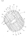
FIG. 1 is a perspective drawing illustrating a cage of a first example of an embodiment of the present invention. -
FIG. 2 is a perspective drawing of the cage of the first example as seen from a different angle (from below inFIG. 1 ). -
FIG. 3 is a perspective drawing illustrating one end section and its adjacent area of the cage of the first example. -
FIG. 4 is a perspective drawing illustrating the other end section and its adjacent area of the cage of the first example. -
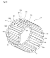
FIG. 5 is a perspective drawing illustrating a cage of a second example of an embodiment of the present invention, and illustrates the state as seen from the opposite side in the axial direction than that inFIG. 1 . -
FIG. 6 is a perspective drawing of the cage of the second example as seen from a different angle (from below inFIG. 5 ). -
FIG. 7 is a perspective drawing illustrating one end section and its adjacent area of the cage of a third example of an embodiment of the present invention. -
FIG. 8 is a perspective drawing illustrating one end section and its adjacent area of the cage of a fourth example of an embodiment of the present invention. -
FIG. 9 is a perspective drawing illustrating one end section and its adjacent area of the cage of a fifth example of an embodiment of the present invention. -
FIG. 10 is a perspective drawing illustrating one end section and its adjacent area of the cage of a sixth example of an embodiment of the present invention. -
FIG. 11 is a perspective drawing illustrating one end section and its adjacent area of the cage of a seventh example of an embodiment of the present invention. -
FIG. 12 is a perspective drawing illustrating one end section and its adjacent area of the cage of a eighth example of an embodiment of the present invention. -
FIG. 13 is a perspective drawing illustrating one end section and its adjacent area of the cage of a ninth example of an embodiment of the present invention. -
FIG. 14 is a perspective drawing illustrating one end section and its adjacent area of the cage of a tenth example of an embodiment of the present invention. -
FIG. 15 is a perspective drawing illustrating a cage of an eleventh example of an embodiment of the present invention, and illustrates the state as seen from the opposite side in the axial direction than that inFIG. 1 . -
FIG. 16 is a perspective drawing of the cage of the eleventh example as seen from a different angle (from below inFIG. 15 ). -
FIG. 17 is a perspective drawing illustrating a cage of a twelfth example of an embodiment of the present invention. -
FIG. 18 is a perspective drawing illustrating the cage of the twelfth example, and illustrates the state as seen from the opposite side in the axial direction than that inFIG. 17 . -
FIG. 19 is a perspective drawing illustrating the other end section and its adjacent area of the cage of the twelfth example. -
FIG. 20 is a perspective drawing illustrating a cage of a thirteenth example of an embodiment of the present invention. -
FIG. 21 is a perspective drawing illustrating the cage of the thirteenth example, and illustrates the state as seen from the opposite side in the axial direction than that inFIG. 20 . -
FIG. 22 is a perspective drawing illustrating the other end section and its adjacent area of the cage of the thirteenth example. -
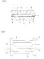
FIG. 23 is a cross-sectional drawing of a rotational support section in which a radial roller bearing with cage is assembled. -
FIG. 24 is a view of part in the circumferential direction of a cage as seen in the radial direction. -
FIG. 25 is a perspective drawing of a conventional cage for a radial roller bearing. -
FIG. 1 to FIG. 4 illustrate a first example of an embodiment of the present invention. Thecage 7b for a radial roller (needle) bearing of this example comprises a pair ofrim sections column sections 9 that are provided intermittently in the circumferential direction and span between therim sections column sections 9 that are adjacent in the circumferential direction, and therim sections pockets 10 that hold rollers 6 (refer toFIG. 23 ) so as to be able to roll freely. - In portions of the circumferential surface of the
rim sections pockets 10,concave sections 16c that are recessed inward in the radial direction andconcave sections 16d that are recessed outward in the radial direction are provided so as to alternate in the circumferential direction and so as to differ with each other between therim sections concave sections 16c andconcave sections 16d, which are formed in opposite directions in the radial direction, are arranged one by one in the portions on both sides in the axial direction of thepockets 10. Moreover, the width dimension in the circumferential direction of theseconcave sections pockets 10, and the depth dimension in the radial direction is 1/2 the thickness dimension in the radial direction of therim sections concave sections pockets 10 in the axial direction. - A
non-continuous section 11a is provided at one location in the circumferential direction of thecage 7b. Theend sections non-continuous section 11a fit with each other by way of afitting section 13a. Particularly, in this example, an insidefitting piece 17 is formed in the middle section (center section) in the axial direction of oneend section 12c of theseend sections other end section 12d. On the other hand, a pair of outsidefitting pieces other end section 12d so as to extend in the circumferential direction toward the oneend section 12c. - In this example, the inside
fitting piece 17 and outsidefitting pieces fitting piece 17 is the same as dimension in the axial direction of theoutside fitting pieces fitting piece 17 and outsidefitting pieces end sections fitting piece 17 is the same as the dimension in the radial direction of the oneend section 12c, and the dimension in the radial direction of theoutside fitting pieces other end section 12d. As illustrated inFIG. 4 , one of theoutside fitting pieces 18a is provided on one end section in the axial direction of the outer-diameter side half section of theother end section 12d, and the other outsidefitting piece 18b is provided on the other end section in the axial direction of the inner-diameter side half section of theother end section 12d. In this way, theoutside fitting pieces - In the construction in the figures, construction is such that the surfaces on both side in the radial direction of the
outside fitting pieces fitting piece 18a that is provided on the outer-diameter side half section of theend section 12d and the outside surface in the radial direction of the outsidefitting piece 18b that is provided on the inner-diameter side half section of theend section 12d can be inclined in a direction such that the dimension in the radial direction of theoutside fitting pieces cage 7b toward the end sides in the axial direction (rim sections - In either case, when the
cage 7b having this kind of construction is assembled in a radial roller bearing, the insidefitting piece 17 is located in the portion between theoutside fitting pieces FIG. 1 andFIG. 2 . As a result, it is possible to fit the insidefitting piece 17 and theoutside fitting pieces fitting piece 17 and theoutside fitting pieces fitting piece 17 closely face the other side surface (side surface on the left side inFIG. 4 ) in the axial direction of the outsidefitting piece 18a and the one side surface (side surface on the right side inFIG. 4 ) of the outsidefitting piece 18b. - The
cage 7b of this example, having this kind of construction, can be manufacturing using axial draw molding, and during use, theend sections non-continuous section 11a can be fitted together so that relative displacement in the radial direction is possible, and so that relative displacement in the axial direction is not possible. - In other words, in this example,
fitting section 13a comprises an insidefitting piece 17 that is provided on oneend section 12c, and a pair of outsidefitting pieces other end section 12d, and by placing the insidefitting piece 17 in the portion between theoutside fitting pieces fitting piece 17 and theoutside fitting pieces fitting section 13a is such that theend sections cage 7b of this example, during operation, the insidefitting piece 17 and outsidefitting pieces fitting section 13a are not pressed in the radial direction, so damage such as wear of these pieces does not occur, and the diameter of thecage 7b can expand due to the action of centrifugal force. Moreover, the force required to cause theend sections non-continuous section 11a to expand or contract smoothly. As a result, when assembled in a radial roller bearing that is assembled in a manual transmission or the like, it is possible to effectively prevent fretting wear. - Furthermore, the
cage 7b of this example is constructed so that theoutside fitting pieces outside fitting pieces fitting piece 17 can be pulled out in the axial direction without interference with theoutside fitting pieces rim sections concave sections 16c that are recessed inward in the radial direction, andconcave sections 16d that are recessed outward in the radial direction are formed so as to alternate in the circumferential direction in the portions that are aligned in the axial direction with thepockets 10, so the portion of the split molds that are provided for forming thepockets 10 can be pulled out in the axial direction without interference with therim sections - In this way, the
cage 7b of this example is regulated to a shape such that a pair of split molds can be separated in the axial direction without damaging the cage after injection molding, so thecage 7b can be manufactured using axial draw molding. More specifically, the cage of this example can be manufactured such that injection molding using synthetic resin is performed in the same was as in the case of a typical synthetic resin cage in which polyamide resin, polyphenylene sulfide resin, or these resins mixed with reinforcement fibers is injected into the cavity of an axial draw mold (mold tool) having a pair of split molds (not illustrated in the figure), after which the split molds are pulled out and removed in the axial direction. - Therefore, the
cage 7b of this example can be manufactured using axial draw molding that is able to keep manufacturing costs low, and theend sections non-continuous section 11a can fit together so that relative displacement in the radial direction is possible, and so that relative displacement in the axial direction is not possible. - The
cage 7b of this example is manufactured using axial draw molding, so in the state immediately after the pair of split molds are pulled out in the axial direction, theend sections end sections cage 7b being cooled to room temperature, the diameter of the cage contracts, so as illustrated in the figure, theend sections cage 7b will not contract as desired, however, thecage 7b is manufactured using synthetic resin and has high elasticity, so after assembly it is elastically deformed by opposing members and put into the desired shape. - The other construction, functions and effects of this example, including assembling the
cage 7b around the shaft where there is an obstacle such as an outward facing flange shaped section by expanding the width of thenon-continuous section 11a, are the same as in the conventional construction. -
FIG. 5 andFIG. 6 illustrate a second example of an embodiment of the present invention. In the case of thecage 7c of this example, the positions where theoutside fitting pieces fitting section 13b are formed differ from in the construction of the first example of an embodiment. More specifically, the positions in the radial direction of the pair of outsidefitting pieces other end section 12d are opposite from the case in the first example, where the outsidefitting piece 18a is formed on one end section in the axial direction of the inner-diameter side half section of theend section 12d, and the outsidefitting piece 18b is formed on the other end section in the axial direction of the outer-diameter side half section of theend section 12d. In this example as well, theseoutside fitting pieces - In the case of the
cage 7c of this example having this kind of construction, as in the case of the first example of an embodiment, thecage 7c can be manufacturing using axial draw molding, and theend sections non-continuous section 11a can be fitted together by way of thefitting section 13b so that relative displacement in the radial direction is possible and so that relative displacement in the axial direction is not possible. The other construction, functions and effects of this example are the same as in the first example of an embodiment. -
FIG. 7 illustrates a third example of an embodiment of the present invention. In the case of thecage 7d of this example, the shape of the inside fitting piece 17a of the fitting section 13c is devised so that after injection molding, transformation such as shrunken depressions or curves in the insidefitting piece 17 is prevented. In other words, in this example, cut awaysections section 19a in a portion on the inner-diameter side of one side in the axial direction (left side inFIG. 7 ) of the inside fitting piece 17a, a cut awaysection 19b is formed in a portion on the outer-diameter side of the other side in the axial direction (right side inFIG. 7 ) of the inside fitting piece 17a. The inside fitting piece 17a of this example in which these kinds of cut awaysections sections - Together the outside
fitting piece 18a that is formed on the outer-diameter side half section of theother end section 12d is located on one side in the axial direction of the inside fitting piece 17a, and the outsidefitting piece 18b that is formed on the inner-diameter side half section of theother end section 12d is located on the other side in the axial direction of the inside fitting piece 17a. In this way, even when cut awaysections outside fitting pieces cage 7d, as well as reduce the material cost. The other construction, functions and effects of this example are the same as in the first example of an embodiment. -
FIG. 8 illustrates a fourth example of an embodiment of the present invention. In the case of thecage 7h of this example, as is in the case of the third example, rectangular shaped cut awaysections fitting piece 17b. Particularly in the case of this example, the length dimension in the axial direction of the cut awaysections sections section 19c is formed in a portion of the inner-diameter side of one side in the axial direction (left side inFIG. 8 ) of the insidefitting piece 17b, and a cut awaysection 19d is formed in a portion of the outer-diameter side of the other side in the axial direction (right side inFIG. 8 ) of the insidefitting piece 17b. These cut awaysections end section 12c. - In doing so, the inside
fitting piece 17b comprises a pair of insidefitting elements non-continuous section 22 in the center section in the axial direction of theend section 12c. Of these, the insidefitting element 23a is provided on the outer-diameter side half section of a portion that is near one side in the axial direction of theend section 12c, and the insidefitting element 23b is provided on the inner-diameter side half section of a portion that is near the other side in the axial direction of theend section 12c. The insidefitting piece 17b having this kind of construction is made by injection molding with part of one split mold (mold tool element) that is located on one side in the axial direction and part of another split mold that is located on the other side in the axial direction overlapped in the radial direction in the center section in the axial direction. - Moreover, the outside
fitting piece 18a that is formed on the outer-diameter side half section of theother end section 12d is located on one side in the axial direction of the insidefitting piece 17b (insidefitting element 23a), and the outsidefitting piece 18b that is formed on the inner-diameter side half section of theend section 12d is located on the other side in the axial direction of the insidefitting piece 17b (insidefitting element 23b). In this way, even when cut awaysections fitting piece 17b, the insidefitting piece 17b and theoutside fitting pieces - In the case of this example having construction such as described above, the volume of the inside
fitting piece 17b is greatly reduced. Therefore, it is possible to suppress changes in flow of material during injection molding, and it is possible to effectively prevent the occurrence of deformation such as shrinkage depressions or bending of the insidefitting elements fitting piece 17b. Therefore, it is possible to improve the precision of the dimensions of the insidefitting elements cage 7h to an even higher degree. The other construction, functions and effects of this example are the same as in the first example and third example of an embodiment. -
FIG. 9 illustrates a fifth example of an embodiment of the present invention. Thecage 7i of this example is such that trapezoidal column shaped cut awaysections fitting piece 17c. In doing so, the boundary surfaces in the axial direction of the insidefitting piece 17c with the cut awaysections surfaces tapered surfaces FIG. 9 ) going toward the outside in the radial direction. - In the case of this example having this kind of construction, it is possible to reduce the volume of the inside
fitting piece 17c while at the same time maintaining the strength and rigidity of the insidefitting piece 17c. Therefore, even when the insidefitting piece 17c and theoutside fitting pieces fitting piece 17c. Moreover, it is also possible to reduce the weight and cost of materials of thecage 7i. The other construction, functions and effects of this example are the same as in the first example and third example of an embodiment. -
FIG. 10 illustrates a sixth example of an embodiment of the present invention. In the case of the cage 7j of this example as well, trapezoidal column shaped cut awaysections fitting piece 17d. Moreover, the pair of cut awaysections end section 12c. As a result, the insidefitting piece 17c comprises a pair of trapezoidal column shaped insidefitting elements - Moreover, the boundary surfaces in the axial direction of the inside
fitting piece 17d with the cut awaysections surfaces FIG. 10 ) going toward the outside in the radial direction. More specifically, on theend section 12c, the surface on the other side in the axial direction (surface on the right side inFIG. 10 ) of the insidefitting element 23c that is provided on the outer-diameter side half section of a portion near one side in the axial direction, and the surface on one side in the axial direction of the insidefitting element 23d that is provided on the inner-diameter side half section of a portion near the other side in the axial direction are taperedsurfaces surfaces - In the case of this example having this kind of construction, it is possible to greatly reduce the volume of the inside
fitting piece 17d while at the same time maintain the strength and rigidity of the insidefitting elements fitting elements outside fitting pieces fitting elements -
FIG. 11 illustrates a seventh example of an embodiment of the present invention. In the case of thecage 7k of this example, cut awaysections fitting piece 17e. The pair of cut away sections are continuous in the radial direction in the center section in the axial direction of theend section 12c. As a result, the insidefitting piece 17e comprises a pair of insidefitting elements - Moreover, the boundary surfaces in the axial direction of the inside
fitting piece 17e with the cut awaysections surfaces end section 12c, the side surface on the outer-diameter side of the other side surface in the axial direction (right side surface inFIG. 11 ) of the insidefitting element 23e that is provided on the outer-diameter side half section of a portion near one side in the axial direction (left side inFIG. 11 ) is atapered surface 24e that is inclined in a direction toward one side in the axial direction going toward the outside in the radial direction. Moreover, the side surface on the inner-diameter side of the other side surface in the axial direction of the insidefitting element 23e is atapered surface 24f that is inclined toward one side in the axial direction going toward the inside in the radial direction. On the other hand, on theend section 12c, the side surface on the outer-diameter side of one side surface (left side surface inFIG. 11 ) in the axial direction of the insidefitting element 23f that is provided on the inner-diameter side half section of a portion near the other side (right side inFIG. 11 ) in the axial direction is atapered surface 24g that is inclined in a direction toward the other side going toward the outside in the radial direction. Moreover, the side surface on the inner-diameter side of the one side surface in the axial direction of the insidefitting element 23f is atapered surface 24h that is inclined in a direction toward the other side in the axial direction going toward the inside in the radial direction. - In the case of this example having this kind of construction, as in the sixth example of an embodiment, it is possible to greatly reduce the volume of the inside
fitting piece 17e while maintaining the strength and rigidity of the insidefitting elements cage 7k at an even higher degree. The other construction, functions and effects of this example are the same as in the first example, third example, fourth example and sixth example of an embodiment. -
FIG. 12 illustrates an eighth example of an embodiment of the present invention. Thecage 71 of this example is such that trapezoidal column shaped cut awaysections 19k, 19l, the cross-sectional shape of which does not change in the radial direction, are formed in portions on opposite side in the radial direction of portions on both sides in the axial direction of the insidefitting piece 17f. As a result, the boundary surfaces in the axial direction of the insidefitting piece 17f with the cut awaysections 19k, 19l are taperedsurfaces tapered surfaces surface 24i that is provided on the inside in the radial direction is inclined in a direction toward one side (left side inFIG. 12 ) in the axial direction going toward one side (rear side in the front/rear direction inFIG. 12 ) in the circumferential direction, and the taperedsurface 24j that is provided on the outside in the radial direction is inclined toward the other side (right side inFIG. 12 ) in the axial direction going toward the one side in the circumferential direction. - In the case of this example having this kind of construction, as in the fifth example of an embodiment, it is possible to reduce the volume of the inside
fitting piece 17f while at the same time maintaining the strength and rigidity of the insidefitting piece 17f. Particularly, in the case of this example, it is possible to keep the dimension in the axial direction of the base end section of the insidefitting piece 17f large, so is advantageous in maintaining the strength and rigidity. Moreover, together with reducing the weight of thecage 71, it is also possible to reduce the material cost. The other construction, functions and effects of this example are the same as in the first example, third example and fifth example. -
FIG. 13 illustrates a ninth example of an embodiment of the present invention. In the case of thecage 7m of this example, trapezoidal column shaped cut awaysections fitting piece 17g. Particularly, in the case of this example, the length dimensions in the axial direction of the cut awaysections sections - In this example having this kind of construction, it is possible to reduce the volume of the inside
fitting piece 17g more than in the eighth example of an embodiment. Moreover, it is possible to keep the dimension in the axial direction of the base end section of the insidefitting piece 17g large, so is advantageous in maintaining the strength and rigidity. In addition, it is possible to further reduce the weight and material costs of thecage 7m. The other construction, functions and effects of this example are the same as in the first example, third example and eighth example of an embodiment. -
FIG. 14 illustrates a tenth example of an embodiment of the present invention. In the case of thecage 7h of this example, trapezoidal column shaped cut awaysections 19o, 19p, the cross-section shape of which does not change in the radial direction, are formed in portions on opposite side in the radial direction of portions on both sides in the axial direction of the insidefitting piece 17h. Moreover, the pair of cut awaysections 19o, 19p are continuous in the radial direction in the center section in the axial direction of theend section 12c. As a result, the insidefitting piece 17h comprises a pair of trapezoidal column shaped insidefitting elements - The boundary surfaces in the axial direction of the inside
fitting piece 17h with the cut awaysections 19o, 19p are taperedsurfaces 24k, 24l that are inclined in a direction toward the inside in the axial direction going toward one side (rear side in the front/rear direction inFIG. 14 ) in the circumferential direction. More specifically, on theend section 12c, the surface on the other side (right side surface inFIG. 14 ) in the axial direction of the insidefitting element 23g that is provided on the outer-diameter side half section of a portion near one side in the axial direction is atapered surface 24k that is inclined in a direction toward the other side (right side inFIG. 14 ) in the axial direction going toward one side in the circumferential direction. On theend section 12c, the surface on one side (left side surface inFIG. 14 ) in the axial direction of the insidefitting element 23h that is provided on the inner-diameter side half section of a portion near the other side in the axial direction is a tapered surface 24l that is inclined in a direction toward one side (left side inFIG. 14 ) in the axial direction going toward one side in the circumferential direction. - In the case of this example having this kind of construction, as in the sixth example and seventh example of an embodiment, it is possible to greatly reduce the volume of the inside
fitting piece 17h while at the same time maintaining strength and rigidity of the insidefitting elements fitting elements cage 7h. The other construction, functions and effects of this example are the same as in the first example, third example, fourth example, sixth example and seventh example of an embodiment. -
FIG. 15 andFIG. 16 illustrate an eleventh example of an embodiment of the present invention. In the case of thecage 7e of this example, both end sections in the axial direction of thefitting section 13d are offset further toward (biased toward) the center side in the axial direction than the side surfaces (outside surfaces) in the axial direction of therim sections fitting section 13d is provided only in the middle section in the axial direction, having both end sections in the axial direction of thecage 7e removed. Therefore, in this example, theoutside fitting pieces fitting section 13d are formed being offset toward the center side in the axial direction and are not formed on the end sections in the axial direction of theend section 12d. That is, theoutside fitting pieces outside fitting pieces insertion spaces 20 are formed in portions on both sides in the axial direction of thefitting section 13d by opening up portions on both sides in the radial direction and portions on opposites sides in the axial direction of thefitting section 13d. - In the case of
cage 7e of this example, provided withinsertion spaces 20 such as these, it is possible to insert positioning pins (not illustrated in the figure) inside theseinsertion spaces 20 when performing automatic assembly of the radial roller bearing (work of inserting rollers into the pockets 10). Therefore, by accurately regulating the position in the circumferential direction of the positioning pins, it is possible to accurately match the position in the circumferential direction of thepockets 10 to the insertion position of the rollers 6 (refer toFIG. 23 ). As a result, it is possible to improve the efficiency of the work of assembling the radial roller bearing. Furthermore, together with being able to reduce the weight of thecage 7e by the amount that theinsertion spaces 20 were formed, there is also an advantage in that it is possible to prevent shrinkage depressions during injection molding. The other construction, functions and effects of this example are the same as in the first example of an embodiment. -
FIG. 17 to FIG. 19 illustrate a twelfth example of an embodiment of the present invention. In the case of thecage 7f of this example, the shapes of theoutside fitting pieces fitting section 13e have been devised, making it more difficult for the insidefitting piece 17, which is located in the portion between theseoutside fitting pieces outside fitting pieces fitting piece 18e that is provided on one side (right side inFIG. 19 ) in the axial direction of theother end section 12d comprises a pair of rectangular plate shaped (partial cylindrical shaped) outside fittingthin plates fitting groove plates end section 12d. Of these, the outside fittingthin plate 21a is provided on the outside end section in the radial direction of theend section 12d, and the outside fittingthin plate 21b is provided on the inside end section in the radial direction of theend section 12d. On the other hand, the outsidefitting piece 18f that is provided on the other side (left side inFIG. 19 ) in the axial direction of theend section 12d is such that the dimension in the radial direction is 1/3 the dimension in the radial direction of theend section 12d, and is provided in the center section in the radial direction of theend section 12d. In the case of this example as well, the outsidefitting piece 18e (outside fittingthin plates fitting piece 18f do not overlap each other with regard to the axial direction. - In this example, the dimension in the radial direction from the outside surface in the radial direction of the outside
fitting piece 18e (outside surface in the radial direction of the outside fittingthin plate 21a on the outside in the radial direction) to the inside surface in the radial direction (inside surface in the radial direction of the outside fittingthin plate 21b on the inside in the radial direction) can be kept sufficiently greater (about two times greater) than the outsidefitting piece 18a in the first example of an embodiment. Therefore, it becomes difficult for the insidefitting piece 17 to ride up on the outsidefitting piece 18e. Furthermore, in this example, the outsidefitting piece 18f is provided in the center section in the radial direction of theend section 12d, so when compared with the case of being biased in the radial direction, it becomes difficult for the insidefitting piece 17 to ride up on the outsidefitting piece 18f. As a result, in the case of this example, thefitting section 13e is able to effectively prevent relative displacement in the axial direction of theend sections -
FIG. 20 to FIG. 22 illustrate a thirteenth example of an embodiment of the present invention. In the case of thecage 7g of this example as well, the shapes of theoutside fitting pieces fitting section 13f are devised such that it is more difficult for the insidefitting piece 17, which is located in the portion between theseoutside fitting pieces outside fitting pieces fitting piece 18g that is provided on one side (right side inFIG. 22 ) in the axial direction of theother end section 12d comprises a pair of rectangular plate shaped (partial cylindrical shaped) outside fittingthin plates thin plates end section 12d. Of these, the outside fittingthin plate 21c is provided on the outside end section in the radial direction of theend section 12d, and the outside fittingthin plate 21d is provided in the portion near the inside in the radial direction of theend section 12d (second position from the inner-diameter side when theend section 12d is divided into four in the radial direction). - Moreover, the outside
fitting piece 18h that is provided on the other side (left side inFIG. 22 ) in the axial direction of theend section 12d also comprises a pair of rectangular plate shaped (partial cylindrical shaped) outside fittingthin plates thin plates end section 12d. Of these, the outsidefitting groove plate 21e is provided in the portion near the outside in the radial direction of theend section 12d (second position from the outer-diameter side when theend section 12d is divided into four in the radial direction), and the outside fittingthin plate 21f is provided on the inside end section in the radial direction of theend section 12d. In the case of this example, the outsidefitting piece 18g (outside fittingthin plates fitting piece 18h (outside fittingthin plates - In this example, the dimension in the radial direction from the outside surface in the radial direction of the outside
fitting piece 18g (outside surface in the radial direction of the outside fittingthin plate 21c on the outside in the radial direction) to the inside surface in the radial direction (inside surface in the radial direction of the outside fittingthin plate 21d on the inside in the radial direction) can be kept sufficiently greater than in the case of the outsidefitting piece 18a in the first example of an embodiment (about 1.5 times greater). Therefore, it becomes difficult for the insidefitting piece 17 to ride up on the outsidefitting piece 18g. Similarly, the dimension in the radial direction from the outside surface in the radial direction of the outsidefitting piece 18h (outside surface in the radial direction of the outside fittingthin plate 21e on the outside in the radial direction) to the inside surface in the radial direction (inside surface in the radial direction of the outside fittingthin plate 21f on the inside in the radial direction) can be kept sufficiently greater than in the case of the outsidefitting piece 18b in the first example of an embodiment (about 1.5 times greater). Therefore, it becomes difficult for the insidefitting piece 17 to ride up on the outsidefitting piece 18h. As a result, in this example as well, thefitting section 13f is able to effectively prevent relative displacement in the axial direction of theend sections - The construction of all of the examples of an embodiment of the present invention can be appropriately combined. Moreover, the shapes of the inside fitting piece and outside fitting pieces are not limited to rectangular shapes, and it is possible to employ other shapes such as triangular shapes and the like. Furthermore, in the twelfth example and thirteenth example of an embodiment, the case of constructing the outside fitting pieces with two outside fitting thin plates was explained, however, the number of outside fitting groove plates of the outside fitting pieces is not limited to two, and depending on the diameter or material of the cage, could be three or more. It is also not necessary to make the dimension in the radial direction of the outside fitting thin plates of the outside fitting pieces be the same, and can be different.
-
- 1
- Radial roller bearing
- 2
- Outer-diameter side member
- 3
- Outer-ring raceway
- 4
- Shaft
- 5
- Inner-ring raceway
- 6
- Roller
- 7, 7a to 7h
- Cage
- 8, 8a to 8d
- Rim section
- 9
- Column section
- 10
- 11, 11a
- Non-continuous section
- 12a to 12d
- End section
- 13, 13a to 13f
- Fitting section
- 14a, 14b
- Outer-diameter side fitting piece
- 15a, 15b
- Inner-diameter side fitting piece
- 16a to 16d
- Concave section
- 17, 17a to 17h
- Inside fitting piece
- 18a to 18h
- Outside fitting piece
- 19a to 19p
- Cut away section
- 20
- Insertion space
- 21a to 21f
- Outside fitting thin plate
- 22
- Non-continuous section
- 23a to 23h
- Inside fitting element
Claims (6)
- A cage (7) for a radial roller bearing (1), that is made into a single piece by injection molding using an axial draw mold having a pair of split molds,
the cage (7) comprising: a pair of rim sections (8), a plurality of column sections (9), a plurality of pockets (10) and a fitting section (13), and provided with a non-continuous section (11, 22) at one location in the circumferential direction, wherein
the pair of rim sections (8) is incomplete ring shaped, and is provided concentric to each other with a space between them in the axial direction, with concave sections (16) that are recessed in the radial direction and that are formed at positions of the circumferential surfaces of these rim sections (8) that are aligned in the axial direction with the pockets (10), and the formation locations of these concave sections (16) are opposite in the radial direction on both sides in the axial direction of the pockets (10);
the column sections (9) are provided intermittently in the circumferential direction and span between the rim sections (8);
the pockets (10) are provided in portions that are surrounded on four sides by the rim sections (8) and the column sections (9) that are adjacent in the circumferential direction; and
the fitting section (13) fits together end sections (12) that are provided on both sides of the non-continuous section (11, 22);
the fitting section (13) comprises: an inside fitting piece (17) that is provided in the middle section in the axial direction of one of the end sections (12), and extends in the circumferential direction toward the other end section (12); and a pair of outside fitting pieces (18) that are provided in separated portions on both sides in the axial direction of the other end section (12), and extend in the circumferential direction toward the one end section (12); and by placing the inside fitting piece (17) in the portion between the outside fitting pieces (18), the inside fitting piece (17) and the outside fitting pieces (18) fit together in the axial direction without the inside fitting piece (17) and the outside fitting pieces (18) overlapping each other in the radial direction. - The cage (7) for a radial roller bearing (1) according to claim 1, wherein cut away sections (19) are formed in portions on opposite side in the radial direction of portions on both sides in the axial direction of the inside fitting pieces (17).
- The cage (7) for a radial roller bearing (1) according to claim 2, wherein boundary surfaces in the axial direction of the inside fitting piece (17) with the cut away sections (19) are tapered surfaces.
- The cage (7) for a radial roller bearing (1) according to claim 2, wherein by making the pair of cut away sections (19) continuous in the radial direction, the inside fitting piece (17) comprises a pair of inside fitting elements (23) that are separated in the axial direction.
- The cage (7) for a radial roller bearing (1) according to claim 1, wherein by making the end sections (12) in the axial direction of the pair of outside fitting pieces (18) be offset further toward the center side in the axial direction than the side surface in the axial direction of the rim sections (8), insertion spaces (20) are formed in the portions on both sides of the fitting section (13).
- The cage (7) for a radial roller bearing (1) according to claim 1, wherein the outside fitting pieces (18) comprises a plurality of outside fitting thin plates (21) that are separated in the radial direction.
Applications Claiming Priority (3)
| Application Number | Priority Date | Filing Date | Title |
|---|---|---|---|
| JP2012178317 | 2012-08-10 | ||
| JP2012201216A JP6003433B2 (en) | 2012-08-10 | 2012-09-13 | Radial roller bearing cage |
| PCT/JP2012/076737 WO2014024327A1 (en) | 2012-08-10 | 2012-10-16 | Radial roller bearing cage |
Publications (3)
| Publication Number | Publication Date |
|---|---|
| EP2884127A1 true EP2884127A1 (en) | 2015-06-17 |
| EP2884127A4 EP2884127A4 (en) | 2016-03-30 |
| EP2884127B1 EP2884127B1 (en) | 2019-02-20 |
Family
ID=50067603
Family Applications (1)
| Application Number | Title | Priority Date | Filing Date |
|---|---|---|---|
| EP12879154.8A Not-in-force EP2884127B1 (en) | 2012-08-10 | 2012-10-16 | Radial roller bearing cage |
Country Status (6)
| Country | Link |
|---|---|
| US (1) | US9145917B2 (en) |
| EP (1) | EP2884127B1 (en) |
| JP (1) | JP6003433B2 (en) |
| KR (1) | KR101521379B1 (en) |
| CN (1) | CN104204576B (en) |
| WO (1) | WO2014024327A1 (en) |
Families Citing this family (5)
| Publication number | Priority date | Publication date | Assignee | Title |
|---|---|---|---|---|
| WO2012036154A1 (en) * | 2010-09-14 | 2012-03-22 | 日本精工株式会社 | Single-joint cage |
| JP6269021B2 (en) * | 2013-12-17 | 2018-01-31 | 日本精工株式会社 | Radial roller bearing cage |
| CN104895931B (en) * | 2015-05-26 | 2018-02-02 | 德清恒富机械有限公司 | needle bearing |
| US10837488B2 (en) | 2018-07-24 | 2020-11-17 | Roller Bearing Company Of America, Inc. | Roller bearing assembly for use in a fracking pump crank shaft |
| DE102020127445A1 (en) * | 2020-10-19 | 2022-04-21 | Schaeffler Technologies AG & Co. KG | Roller bearing cage with cage lock and method for assembling the roller bearing cage |
Family Cites Families (14)
| Publication number | Priority date | Publication date | Assignee | Title |
|---|---|---|---|---|
| DE2041342C3 (en) * | 1970-08-20 | 1981-11-26 | Industriewerk Schaeffler Ohg, 8522 Herzogenaurach | Plastic cage for roller bearings |
| JPS5129385Y2 (en) * | 1971-11-10 | 1976-07-24 | ||
| US3881790A (en) * | 1973-08-06 | 1975-05-06 | Federal Mogul Corp | One piece molded plastic retainer for cylindrical roller bearings and method of manufacture |
| JPS54111242U (en) * | 1978-01-20 | 1979-08-04 | ||
| JPS5927539Y2 (en) * | 1979-02-09 | 1984-08-09 | 光洋精工株式会社 | Split cage for rolling bearings |
| US4472007A (en) * | 1983-04-04 | 1984-09-18 | The Torrington Company | Cage assembly |
| JPS6071728U (en) * | 1983-10-25 | 1985-05-21 | 日本精工株式会社 | Cage for rolling bearings |
| US4865473A (en) * | 1988-09-06 | 1989-09-12 | The Torrington Company | Single split cage locking tab |
| DE4038444A1 (en) * | 1990-12-01 | 1992-06-04 | Schaeffler Waelzlager Kg | SLOTED ROD BODY |
| JP2008008333A (en) * | 2006-06-27 | 2008-01-17 | Nsk Ltd | Manufacturing method of cage for radial roller bearing |
| FR2918137A1 (en) * | 2007-06-29 | 2009-01-02 | Snr Roulements Sa | Bearing cage e.g. cylindrical roller bearing cage, for being mounted on e.g. shaft, has key housed in housing and provided with two walls facing facets of housing, where key has additional pocket for additional cylindrical roller body |
| JP2011089612A (en) * | 2009-10-23 | 2011-05-06 | Jtekt Corp | Cage for needle roller bearing, and needle roller bearing |
| WO2012036154A1 (en) * | 2010-09-14 | 2012-03-22 | 日本精工株式会社 | Single-joint cage |
| US20130272641A1 (en) * | 2010-11-30 | 2013-10-17 | Nsk Ltd. | Split Retainer for a Rolling Bearing |
-
2012
- 2012-09-13 JP JP2012201216A patent/JP6003433B2/en not_active Expired - Fee Related
- 2012-10-16 CN CN201280032179.8A patent/CN104204576B/en not_active Expired - Fee Related
- 2012-10-16 US US13/824,355 patent/US9145917B2/en active Active
- 2012-10-16 WO PCT/JP2012/076737 patent/WO2014024327A1/en not_active Ceased
- 2012-10-16 EP EP12879154.8A patent/EP2884127B1/en not_active Not-in-force
- 2012-10-16 KR KR1020137034432A patent/KR101521379B1/en not_active Expired - Fee Related
Also Published As
| Publication number | Publication date |
|---|---|
| KR101521379B1 (en) | 2015-05-18 |
| US9145917B2 (en) | 2015-09-29 |
| EP2884127A4 (en) | 2016-03-30 |
| JP2014055639A (en) | 2014-03-27 |
| US20150176646A1 (en) | 2015-06-25 |
| EP2884127B1 (en) | 2019-02-20 |
| CN104204576B (en) | 2017-12-29 |
| JP6003433B2 (en) | 2016-10-05 |
| KR20140051863A (en) | 2014-05-02 |
| WO2014024327A1 (en) | 2014-02-13 |
| CN104204576A (en) | 2014-12-10 |
Similar Documents
| Publication | Publication Date | Title |
|---|---|---|
| EP2770221B1 (en) | Radial roller bearing retainer | |
| EP2884127B1 (en) | Radial roller bearing cage | |
| CN102227570B (en) | Roller cage for rolling bearing, particularly double roller cage for cylinder rolling bearing, rolling bearing, and method for producing roller cage for rolling bearing | |
| CN102549284B (en) | Single Split Cage | |
| JP6055357B2 (en) | Resin cage for tapered roller bearings | |
| CN102523750A (en) | Radial roller bearing retainer | |
| EP1961983B1 (en) | Roller bearing, main shaft support structure for wind-driven generator, intermediate element, and retainer segment | |
| CN101331334A (en) | Roller bearings, main shaft support structures for wind turbines, liners and retainer sections | |
| JP4840250B2 (en) | Radial needle bearing | |
| EP2351939B1 (en) | Cage-equipped rollers | |
| US9410579B2 (en) | Cage with parallel pockets for rolling bearing | |
| JP5831120B2 (en) | Radial roller bearing cage | |
| JP7627636B2 (en) | Roller and needle roller bearings | |
| JP5289796B2 (en) | Tapered roller bearing retainer manufacturing method and tapered roller bearing | |
| CN202531655U (en) | Cage for radial needle roller bearing | |
| JP2024146055A (en) | Ball bearing retainer and ball bearing | |
| KR20140116825A (en) | Spacer for rolling bearing having at least a reinforcing beam | |
| JP5834644B2 (en) | One cage | |
| JP2016065634A (en) | Holder for radial roller bearing, and radial roller bearing |
Legal Events
| Date | Code | Title | Description |
|---|---|---|---|
| PUAI | Public reference made under article 153(3) epc to a published international application that has entered the european phase |
Free format text: ORIGINAL CODE: 0009012 |
|
| 17P | Request for examination filed |
Effective date: 20140108 |
|
| AK | Designated contracting states |
Kind code of ref document: A1 Designated state(s): AL AT BE BG CH CY CZ DE DK EE ES FI FR GB GR HR HU IE IS IT LI LT LU LV MC MK MT NL NO PL PT RO RS SE SI SK SM TR |
|
| AX | Request for extension of the european patent |
Extension state: BA ME |
|
| DAX | Request for extension of the european patent (deleted) | ||
| RA4 | Supplementary search report drawn up and despatched (corrected) |
Effective date: 20160225 |
|
| RIC1 | Information provided on ipc code assigned before grant |
Ipc: F16C 11/04 20060101ALN20160219BHEP Ipc: F16C 33/46 20060101AFI20160219BHEP Ipc: F16C 19/26 20060101ALI20160219BHEP Ipc: F16C 19/46 20060101ALI20160219BHEP |
|
| GRAP | Despatch of communication of intention to grant a patent |
Free format text: ORIGINAL CODE: EPIDOSNIGR1 |
|
| STAA | Information on the status of an ep patent application or granted ep patent |
Free format text: STATUS: GRANT OF PATENT IS INTENDED |
|
| RIC1 | Information provided on ipc code assigned before grant |
Ipc: F16C 19/26 20060101ALI20180927BHEP Ipc: F16C 33/46 20060101AFI20180927BHEP Ipc: F16C 19/46 20060101ALI20180927BHEP Ipc: F16C 11/04 20060101ALN20180927BHEP |
|
| RIC1 | Information provided on ipc code assigned before grant |
Ipc: F16C 33/46 20060101AFI20181003BHEP Ipc: F16C 11/04 20060101ALN20181003BHEP Ipc: F16C 19/26 20060101ALI20181003BHEP Ipc: F16C 19/46 20060101ALI20181003BHEP |
|
| INTG | Intention to grant announced |
Effective date: 20181016 |
|
| GRAS | Grant fee paid |
Free format text: ORIGINAL CODE: EPIDOSNIGR3 |
|
| GRAA | (expected) grant |
Free format text: ORIGINAL CODE: 0009210 |
|
| STAA | Information on the status of an ep patent application or granted ep patent |
Free format text: STATUS: THE PATENT HAS BEEN GRANTED |
|
| AK | Designated contracting states |
Kind code of ref document: B1 Designated state(s): AL AT BE BG CH CY CZ DE DK EE ES FI FR GB GR HR HU IE IS IT LI LT LU LV MC MK MT NL NO PL PT RO RS SE SI SK SM TR |
|
| REG | Reference to a national code |
Ref country code: GB Ref legal event code: FG4D |
|
| REG | Reference to a national code |
Ref country code: CH Ref legal event code: EP |
|
| REG | Reference to a national code |
Ref country code: DE Ref legal event code: R096 Ref document number: 602012056983 Country of ref document: DE |
|
| REG | Reference to a national code |
Ref country code: AT Ref legal event code: REF Ref document number: 1098574 Country of ref document: AT Kind code of ref document: T Effective date: 20190315 |
|
| REG | Reference to a national code |
Ref country code: IE Ref legal event code: FG4D |
|
| REG | Reference to a national code |
Ref country code: NL Ref legal event code: MP Effective date: 20190220 |
|
| REG | Reference to a national code |
Ref country code: LT Ref legal event code: MG4D |
|
| PG25 | Lapsed in a contracting state [announced via postgrant information from national office to epo] |
Ref country code: FI Free format text: LAPSE BECAUSE OF FAILURE TO SUBMIT A TRANSLATION OF THE DESCRIPTION OR TO PAY THE FEE WITHIN THE PRESCRIBED TIME-LIMIT Effective date: 20190220 Ref country code: NO Free format text: LAPSE BECAUSE OF FAILURE TO SUBMIT A TRANSLATION OF THE DESCRIPTION OR TO PAY THE FEE WITHIN THE PRESCRIBED TIME-LIMIT Effective date: 20190520 Ref country code: LT Free format text: LAPSE BECAUSE OF FAILURE TO SUBMIT A TRANSLATION OF THE DESCRIPTION OR TO PAY THE FEE WITHIN THE PRESCRIBED TIME-LIMIT Effective date: 20190220 Ref country code: NL Free format text: LAPSE BECAUSE OF FAILURE TO SUBMIT A TRANSLATION OF THE DESCRIPTION OR TO PAY THE FEE WITHIN THE PRESCRIBED TIME-LIMIT Effective date: 20190220 Ref country code: PT Free format text: LAPSE BECAUSE OF FAILURE TO SUBMIT A TRANSLATION OF THE DESCRIPTION OR TO PAY THE FEE WITHIN THE PRESCRIBED TIME-LIMIT Effective date: 20190620 Ref country code: SE Free format text: LAPSE BECAUSE OF FAILURE TO SUBMIT A TRANSLATION OF THE DESCRIPTION OR TO PAY THE FEE WITHIN THE PRESCRIBED TIME-LIMIT Effective date: 20190220 |
|
| PG25 | Lapsed in a contracting state [announced via postgrant information from national office to epo] |
Ref country code: LV Free format text: LAPSE BECAUSE OF FAILURE TO SUBMIT A TRANSLATION OF THE DESCRIPTION OR TO PAY THE FEE WITHIN THE PRESCRIBED TIME-LIMIT Effective date: 20190220 Ref country code: RS Free format text: LAPSE BECAUSE OF FAILURE TO SUBMIT A TRANSLATION OF THE DESCRIPTION OR TO PAY THE FEE WITHIN THE PRESCRIBED TIME-LIMIT Effective date: 20190220 Ref country code: HR Free format text: LAPSE BECAUSE OF FAILURE TO SUBMIT A TRANSLATION OF THE DESCRIPTION OR TO PAY THE FEE WITHIN THE PRESCRIBED TIME-LIMIT Effective date: 20190220 Ref country code: GR Free format text: LAPSE BECAUSE OF FAILURE TO SUBMIT A TRANSLATION OF THE DESCRIPTION OR TO PAY THE FEE WITHIN THE PRESCRIBED TIME-LIMIT Effective date: 20190521 Ref country code: IS Free format text: LAPSE BECAUSE OF FAILURE TO SUBMIT A TRANSLATION OF THE DESCRIPTION OR TO PAY THE FEE WITHIN THE PRESCRIBED TIME-LIMIT Effective date: 20190620 Ref country code: BG Free format text: LAPSE BECAUSE OF FAILURE TO SUBMIT A TRANSLATION OF THE DESCRIPTION OR TO PAY THE FEE WITHIN THE PRESCRIBED TIME-LIMIT Effective date: 20190520 |
|
| REG | Reference to a national code |
Ref country code: AT Ref legal event code: MK05 Ref document number: 1098574 Country of ref document: AT Kind code of ref document: T Effective date: 20190220 |
|
| PG25 | Lapsed in a contracting state [announced via postgrant information from national office to epo] |
Ref country code: DK Free format text: LAPSE BECAUSE OF FAILURE TO SUBMIT A TRANSLATION OF THE DESCRIPTION OR TO PAY THE FEE WITHIN THE PRESCRIBED TIME-LIMIT Effective date: 20190220 Ref country code: EE Free format text: LAPSE BECAUSE OF FAILURE TO SUBMIT A TRANSLATION OF THE DESCRIPTION OR TO PAY THE FEE WITHIN THE PRESCRIBED TIME-LIMIT Effective date: 20190220 Ref country code: ES Free format text: LAPSE BECAUSE OF FAILURE TO SUBMIT A TRANSLATION OF THE DESCRIPTION OR TO PAY THE FEE WITHIN THE PRESCRIBED TIME-LIMIT Effective date: 20190220 Ref country code: CZ Free format text: LAPSE BECAUSE OF FAILURE TO SUBMIT A TRANSLATION OF THE DESCRIPTION OR TO PAY THE FEE WITHIN THE PRESCRIBED TIME-LIMIT Effective date: 20190220 Ref country code: IT Free format text: LAPSE BECAUSE OF FAILURE TO SUBMIT A TRANSLATION OF THE DESCRIPTION OR TO PAY THE FEE WITHIN THE PRESCRIBED TIME-LIMIT Effective date: 20190220 Ref country code: RO Free format text: LAPSE BECAUSE OF FAILURE TO SUBMIT A TRANSLATION OF THE DESCRIPTION OR TO PAY THE FEE WITHIN THE PRESCRIBED TIME-LIMIT Effective date: 20190220 Ref country code: SK Free format text: LAPSE BECAUSE OF FAILURE TO SUBMIT A TRANSLATION OF THE DESCRIPTION OR TO PAY THE FEE WITHIN THE PRESCRIBED TIME-LIMIT Effective date: 20190220 Ref country code: AL Free format text: LAPSE BECAUSE OF FAILURE TO SUBMIT A TRANSLATION OF THE DESCRIPTION OR TO PAY THE FEE WITHIN THE PRESCRIBED TIME-LIMIT Effective date: 20190220 |
|
| REG | Reference to a national code |
Ref country code: DE Ref legal event code: R097 Ref document number: 602012056983 Country of ref document: DE |
|
| PG25 | Lapsed in a contracting state [announced via postgrant information from national office to epo] |
Ref country code: SM Free format text: LAPSE BECAUSE OF FAILURE TO SUBMIT A TRANSLATION OF THE DESCRIPTION OR TO PAY THE FEE WITHIN THE PRESCRIBED TIME-LIMIT Effective date: 20190220 Ref country code: PL Free format text: LAPSE BECAUSE OF FAILURE TO SUBMIT A TRANSLATION OF THE DESCRIPTION OR TO PAY THE FEE WITHIN THE PRESCRIBED TIME-LIMIT Effective date: 20190220 |
|
| PLBE | No opposition filed within time limit |
Free format text: ORIGINAL CODE: 0009261 |
|
| STAA | Information on the status of an ep patent application or granted ep patent |
Free format text: STATUS: NO OPPOSITION FILED WITHIN TIME LIMIT |
|
| PG25 | Lapsed in a contracting state [announced via postgrant information from national office to epo] |
Ref country code: AT Free format text: LAPSE BECAUSE OF FAILURE TO SUBMIT A TRANSLATION OF THE DESCRIPTION OR TO PAY THE FEE WITHIN THE PRESCRIBED TIME-LIMIT Effective date: 20190220 |
|
| 26N | No opposition filed |
Effective date: 20191121 |
|
| PG25 | Lapsed in a contracting state [announced via postgrant information from national office to epo] |
Ref country code: SI Free format text: LAPSE BECAUSE OF FAILURE TO SUBMIT A TRANSLATION OF THE DESCRIPTION OR TO PAY THE FEE WITHIN THE PRESCRIBED TIME-LIMIT Effective date: 20190220 |
|
| PG25 | Lapsed in a contracting state [announced via postgrant information from national office to epo] |
Ref country code: TR Free format text: LAPSE BECAUSE OF FAILURE TO SUBMIT A TRANSLATION OF THE DESCRIPTION OR TO PAY THE FEE WITHIN THE PRESCRIBED TIME-LIMIT Effective date: 20190220 |
|
| PG25 | Lapsed in a contracting state [announced via postgrant information from national office to epo] |
Ref country code: MC Free format text: LAPSE BECAUSE OF FAILURE TO SUBMIT A TRANSLATION OF THE DESCRIPTION OR TO PAY THE FEE WITHIN THE PRESCRIBED TIME-LIMIT Effective date: 20190220 |
|
| REG | Reference to a national code |
Ref country code: CH Ref legal event code: PL |
|
| PG25 | Lapsed in a contracting state [announced via postgrant information from national office to epo] |
Ref country code: LI Free format text: LAPSE BECAUSE OF NON-PAYMENT OF DUE FEES Effective date: 20191031 Ref country code: LU Free format text: LAPSE BECAUSE OF NON-PAYMENT OF DUE FEES Effective date: 20191016 Ref country code: CH Free format text: LAPSE BECAUSE OF NON-PAYMENT OF DUE FEES Effective date: 20191031 |
|
| REG | Reference to a national code |
Ref country code: BE Ref legal event code: MM Effective date: 20191031 |
|
| PG25 | Lapsed in a contracting state [announced via postgrant information from national office to epo] |
Ref country code: BE Free format text: LAPSE BECAUSE OF NON-PAYMENT OF DUE FEES Effective date: 20191031 |
|
| GBPC | Gb: european patent ceased through non-payment of renewal fee |
Effective date: 20191016 |
|
| PG25 | Lapsed in a contracting state [announced via postgrant information from national office to epo] |
Ref country code: GB Free format text: LAPSE BECAUSE OF NON-PAYMENT OF DUE FEES Effective date: 20191016 Ref country code: IE Free format text: LAPSE BECAUSE OF NON-PAYMENT OF DUE FEES Effective date: 20191016 Ref country code: FR Free format text: LAPSE BECAUSE OF NON-PAYMENT OF DUE FEES Effective date: 20191031 |
|
| PG25 | Lapsed in a contracting state [announced via postgrant information from national office to epo] |
Ref country code: CY Free format text: LAPSE BECAUSE OF FAILURE TO SUBMIT A TRANSLATION OF THE DESCRIPTION OR TO PAY THE FEE WITHIN THE PRESCRIBED TIME-LIMIT Effective date: 20190220 |
|
| PG25 | Lapsed in a contracting state [announced via postgrant information from national office to epo] |
Ref country code: MT Free format text: LAPSE BECAUSE OF FAILURE TO SUBMIT A TRANSLATION OF THE DESCRIPTION OR TO PAY THE FEE WITHIN THE PRESCRIBED TIME-LIMIT Effective date: 20190220 Ref country code: HU Free format text: LAPSE BECAUSE OF FAILURE TO SUBMIT A TRANSLATION OF THE DESCRIPTION OR TO PAY THE FEE WITHIN THE PRESCRIBED TIME-LIMIT; INVALID AB INITIO Effective date: 20121016 |
|
| PG25 | Lapsed in a contracting state [announced via postgrant information from national office to epo] |
Ref country code: MK Free format text: LAPSE BECAUSE OF FAILURE TO SUBMIT A TRANSLATION OF THE DESCRIPTION OR TO PAY THE FEE WITHIN THE PRESCRIBED TIME-LIMIT Effective date: 20190220 |
|
| PGFP | Annual fee paid to national office [announced via postgrant information from national office to epo] |
Ref country code: DE Payment date: 20230830 Year of fee payment: 12 |
|
| REG | Reference to a national code |
Ref country code: DE Ref legal event code: R119 Ref document number: 602012056983 Country of ref document: DE |
|
| PG25 | Lapsed in a contracting state [announced via postgrant information from national office to epo] |
Ref country code: DE Free format text: LAPSE BECAUSE OF NON-PAYMENT OF DUE FEES Effective date: 20250501 |