EP2884073A1 - Variable-capacity exhaust turbosupercharger - Google Patents
Variable-capacity exhaust turbosupercharger Download PDFInfo
- Publication number
- EP2884073A1 EP2884073A1 EP13827476.6A EP13827476A EP2884073A1 EP 2884073 A1 EP2884073 A1 EP 2884073A1 EP 13827476 A EP13827476 A EP 13827476A EP 2884073 A1 EP2884073 A1 EP 2884073A1
- Authority
- EP
- European Patent Office
- Prior art keywords
- nozzle
- variable
- mount
- nozzle plate
- nozzle mount
- Prior art date
- Legal status (The legal status is an assumption and is not a legal conclusion. Google has not performed a legal analysis and makes no representation as to the accuracy of the status listed.)
- Granted
Links
Images




Classifications
-
- F—MECHANICAL ENGINEERING; LIGHTING; HEATING; WEAPONS; BLASTING
- F04—POSITIVE - DISPLACEMENT MACHINES FOR LIQUIDS; PUMPS FOR LIQUIDS OR ELASTIC FLUIDS
- F04D—NON-POSITIVE-DISPLACEMENT PUMPS
- F04D27/00—Control, e.g. regulation, of pumps, pumping installations or pumping systems specially adapted for elastic fluids
- F04D27/002—Control, e.g. regulation, of pumps, pumping installations or pumping systems specially adapted for elastic fluids by varying geometry within the pumps, e.g. by adjusting vanes
-
- F—MECHANICAL ENGINEERING; LIGHTING; HEATING; WEAPONS; BLASTING
- F01—MACHINES OR ENGINES IN GENERAL; ENGINE PLANTS IN GENERAL; STEAM ENGINES
- F01D—NON-POSITIVE DISPLACEMENT MACHINES OR ENGINES, e.g. STEAM TURBINES
- F01D17/00—Regulating or controlling by varying flow
- F01D17/10—Final actuators
- F01D17/12—Final actuators arranged in stator parts
- F01D17/14—Final actuators arranged in stator parts varying effective cross-sectional area of nozzles or guide conduits
- F01D17/16—Final actuators arranged in stator parts varying effective cross-sectional area of nozzles or guide conduits by means of nozzle vanes
- F01D17/165—Final actuators arranged in stator parts varying effective cross-sectional area of nozzles or guide conduits by means of nozzle vanes for radial flow, i.e. the vanes turning around axes which are essentially parallel to the rotor centre line
-
- F—MECHANICAL ENGINEERING; LIGHTING; HEATING; WEAPONS; BLASTING
- F02—COMBUSTION ENGINES; HOT-GAS OR COMBUSTION-PRODUCT ENGINE PLANTS
- F02M—SUPPLYING COMBUSTION ENGINES IN GENERAL WITH COMBUSTIBLE MIXTURES OR CONSTITUENTS THEREOF
- F02M26/00—Engine-pertinent apparatus for adding exhaust gases to combustion-air, main fuel or fuel-air mixture, e.g. by exhaust gas recirculation [EGR] systems
-
- F—MECHANICAL ENGINEERING; LIGHTING; HEATING; WEAPONS; BLASTING
- F04—POSITIVE - DISPLACEMENT MACHINES FOR LIQUIDS; PUMPS FOR LIQUIDS OR ELASTIC FLUIDS
- F04D—NON-POSITIVE-DISPLACEMENT PUMPS
- F04D19/00—Axial-flow pumps
- F04D19/02—Multi-stage pumps
-
- F—MECHANICAL ENGINEERING; LIGHTING; HEATING; WEAPONS; BLASTING
- F04—POSITIVE - DISPLACEMENT MACHINES FOR LIQUIDS; PUMPS FOR LIQUIDS OR ELASTIC FLUIDS
- F04D—NON-POSITIVE-DISPLACEMENT PUMPS
- F04D29/00—Details, component parts, or accessories
- F04D29/02—Selection of particular materials
- F04D29/023—Selection of particular materials especially adapted for elastic fluid pumps
-
- F—MECHANICAL ENGINEERING; LIGHTING; HEATING; WEAPONS; BLASTING
- F02—COMBUSTION ENGINES; HOT-GAS OR COMBUSTION-PRODUCT ENGINE PLANTS
- F02B—INTERNAL-COMBUSTION PISTON ENGINES; COMBUSTION ENGINES IN GENERAL
- F02B37/00—Engines characterised by provision of pumps driven at least for part of the time by exhaust
- F02B37/12—Control of the pumps
- F02B37/24—Control of the pumps by using pumps or turbines with adjustable guide vanes
-
- F—MECHANICAL ENGINEERING; LIGHTING; HEATING; WEAPONS; BLASTING
- F05—INDEXING SCHEMES RELATING TO ENGINES OR PUMPS IN VARIOUS SUBCLASSES OF CLASSES F01-F04
- F05D—INDEXING SCHEME FOR ASPECTS RELATING TO NON-POSITIVE-DISPLACEMENT MACHINES OR ENGINES, GAS-TURBINES OR JET-PROPULSION PLANTS
- F05D2220/00—Application
- F05D2220/40—Application in turbochargers
-
- F—MECHANICAL ENGINEERING; LIGHTING; HEATING; WEAPONS; BLASTING
- F05—INDEXING SCHEMES RELATING TO ENGINES OR PUMPS IN VARIOUS SUBCLASSES OF CLASSES F01-F04
- F05D—INDEXING SCHEME FOR ASPECTS RELATING TO NON-POSITIVE-DISPLACEMENT MACHINES OR ENGINES, GAS-TURBINES OR JET-PROPULSION PLANTS
- F05D2300/00—Materials; Properties thereof
- F05D2300/10—Metals, alloys or intermetallic compounds
- F05D2300/17—Alloys
-
- F—MECHANICAL ENGINEERING; LIGHTING; HEATING; WEAPONS; BLASTING
- F05—INDEXING SCHEMES RELATING TO ENGINES OR PUMPS IN VARIOUS SUBCLASSES OF CLASSES F01-F04
- F05D—INDEXING SCHEME FOR ASPECTS RELATING TO NON-POSITIVE-DISPLACEMENT MACHINES OR ENGINES, GAS-TURBINES OR JET-PROPULSION PLANTS
- F05D2300/00—Materials; Properties thereof
- F05D2300/50—Intrinsic material properties or characteristics
- F05D2300/502—Thermal properties
- F05D2300/5021—Expansivity
- F05D2300/50212—Expansivity dissimilar
Definitions
- the present disclosure relates to a variable-geometry exhaust turbocharger including a variable nozzle mechanism.
- variable nozzle mechanism In an exhaust turbocharger used in a diesel engine of a vehicle, a variable nozzle mechanism is widely used.
- the variable nozzle mechanism is disposed between an exhaust gas channel of a scroll shape formed in a turbine housing and a turbine rotor rotatably disposed at the center of the turbine housing to control the flow of the exhaust gas acting on the turbine rotor.
- the variable nozzle mechanism includes a nozzle mount and a nozzle plate which are supported by nozzle supports and spaced from each other.
- a plurality of nozzle vanes are supported rotatably between the nozzle mount and the nozzle plate. The angle of the nozzle vanes is varied to control the flow of the exhaust gas flowing between the nozzle mount and the nozzle plate, and thereby the flow of the exhaust gas acting on the turbine rotor is controlled.
- Japanese Patent No. 4885118 filed by the present applicant discloses an example of a variable-geometry exhaust turbocharger including such a variable nozzle mechanism.
- Patent Document 1 Japanese Patent No. 4885118
- the temperature of exhaust gas discharged from a diesel engine may increase as high as approximately 850°C, causing thermal deformation in a nozzle mount and a nozzle plate formed of stainless steel or the like.
- the amount of thermal deformation is varied between the nozzle mount and the nozzle plate because the nozzle mount contacts the high-temperature exhaust gas at only one face fixed to a bearing housing or the like while the nozzle plate is exposed to the high-temperature exhaust gas at both faces.
- a shear force or a bending moment may be applied to the nozzle supports 6 coupling the nozzle plate 4 and the nozzle mount 2 as illustrated in FIG. 9 , thereby deforming the nozzle supports 6.
- FIG. 10 is a chart of linear expansion coefficients of stainless steel at temperatures of 850°C and 760°C.
- FIG. 11 is a chart of extension rates of stainless steel at temperatures of 850°C and 760°C, and an extension rate difference between the above temperatures.
- An extension rate here means the amount of strain, ⁇ ⁇ ⁇ T, where ⁇ T is the amount of temperature change from the reference temperature To of a material, and ⁇ is the linear expansion coefficient.
- the nozzle plate When the same kind of stainless steel having the same linear expansion coefficient illustrated in FIG. 10 is used for the nozzle mount 2 and the nozzle plate 4, the nozzle plate has an extension rate of 1.56% at a temperature of 850°C while the nozzle mount has an extension rate of 1.34% at a temperature of 760°C as illustrated in FIG. 11 .
- the extension rate difference between the nozzle plate and the nozzle mount is 0.22%.
- the reference temperature To here is 20°C.
- the temperature of exhaust gas discharged from a gasoline engine is expected to be higher than 850°C, which further increases the above difference (extension rate difference) in the amount of thermal deformation between the nozzle mount and the nozzle plate. This may cause an even larger shear force and bending moment to be applied to the nozzle supports.
- At least one embodiment of the present invention was made in view of the above problem of the conventional technique to provide a variable-geometry exhaust turbocharger including a variable nozzle mechanism with a small difference in the amount of thermal deformation between the nozzle mount and the nozzle plate under a high-temperature condition, so that a large shear force or bending moment may not act on the nozzle supports to deform the nozzle supports.
- At least one embodiment of the present invention provides a variable-geometry exhaust turbocharger including: a nozzle mount fixed to a housing; a nozzle support having a first end coupled to a first face of the nozzle mount; a nozzle plate coupled to the second end of the nozzle support and supported to be separated from the first face of the nozzle mount, the nozzle plate having a first face coupled to the nozzle support and a second face which is opposite to the first face and which faces an exhaust gas channel through which exhaust gas flows; a plurality of nozzle vanes rotatably supported between the nozzle mount and the nozzle plate; and a variable nozzle mechanism configured to change vane angles of the nozzle vanes to control a flow of the exhaust gas flowing between the nozzle mount and the nozzle plate.
- the nozzle plate is formed of a material having a smaller linear expansion coefficient than that of a material forming the nozzle mount.
- the nozzle plate which is exposed to the exhaust gas at both sides so that the temperature rises higher, is formed of a material having a smaller linear expansion coefficient than that of a material forming the nozzle mount.
- the nozzle plate is formed of heat-resistant Ni-base alloy, and the nozzle mount is formed of stainless steel.
- the nozzle plate which is exposed to the exhaust gas at both sides so that the temperature rises higher, is formed of heat-resistant Ni-base alloy which has a small linear expansion coefficient, while the nozzle mount is formed of stainless steel which is relatively low cost. As a result, it is possible to reduce the difference in the amount of thermal deformation between the nozzle mount and the nozzle plate under a high-temperature condition and to reduce the material cost.
- the nozzle plate and the nozzle mount are formed of different kinds of heat-resistant Ni-base alloy having different linear expansion coefficients.
- the nozzle plate is formed of heat-resistant Ni-base alloy having a relatively small linear expansion coefficient while the nozzle mount is formed of heat-resistant Ni-base alloy having a relatively large linear expansion coefficient.
- both of the nozzle plate and the nozzle mount are formed of heat-resistant Ni-base alloy, which makes it possible to reduce the difference in the amount of deformation between the nozzle plate and the nozzle mount, and to achieve a variable nozzle mechanism having high heat resistance.
- the materials forming the nozzle plate and the nozzle mount are each selected so that an absolute value of an extension rate difference A defined by the following equation (1) is not greater than 0.20%:
- A ⁇ ⁇ 1 ⁇ T 1 - T 0 - ⁇ ⁇ 2 ⁇ T 2 - T 0
- ⁇ 1 is a linear expansion coefficient of the material forming the nozzle plate
- ⁇ 2 is a linear expansion coefficient of the material forming the nozzle mount
- T1 is a temperature of the nozzle plate during operation of an engine
- T2 is a temperature of the nozzle mount during operation of the engine
- To is a reference temperature.
- variable-geometry exhaust turbocharger of the above embodiment the materials forming the nozzle plate and the nozzle mount are each selected so that the absolute value of an extension rate difference A defined by the equation (1) is not greater than 0.20%. In this way, it is possible to provide a variable-geometry exhaust turbocharger including a variable nozzle mechanism in which the difference in the amount of thermal deformation between the nozzle mount and the nozzle plate under a high-temperature condition is small.
- variable-geometry exhaust turbocharger may be suitably used in a gasoline engine in which the temperature of exhaust gas becomes high.
- variable-geometry exhaust turbocharger including a variable nozzle mechanism in which the difference in the amount of thermal deformation between the nozzle mount and the nozzle plate under a high-temperature condition is small, and therefore a large shear force or bending moment may not be applied to the nozzle supports to deform the nozzle supports.
- FIG. 1 is a cross-sectional view of a variable-geometry exhaust turbocharger according to one embodiment of the present invention.
- FIG. 2 is a cross-sectional view taken along line B-B of FIG. 1 .
- FIG. 3 is a cross-sectional view taken along line A-A of FIG. 2 .
- variable-geometry exhaust turbocharger 1 includes a turbine housing 16 for accommodating a turbine rotor 12, and a bearing housing 18 for accommodating a bearing 22 rotatably supporting a rotational shaft 12a of the turbine rotor 12.
- the turbine housing 16 and the bearing housing 18 are fastened to each other via bolts, for instance.
- a compressor housing for accommodating a compressor rotor coupled to the rotational shaft 12a is coupled to the bearing housing 18 at the opposite side of the turbine housing 16 across the bearing housing 18.
- an exhaust gas channel 20 of a scroll shape is formed on the outer circumferential side of the turbine housing 16.
- the exhaust gas channel 20 communicates with an exhaust-gas manifold (not illustrated), and exhaust gas discharged from an engine flows through the exhaust gas channel 20.
- a variable nozzle mechanism 10 for controlling the flow of the exhaust gas acting on the turbine rotor 12 is disposed between the exhaust gas channel 20 of a scroll shape and the turbine rotor 12.
- variable nozzle mechanism 10 is fixed to the bearing housing 18 by the nozzle mount 2 being fastened to the bearing housing 18 by bolts or the like while the variable nozzle mechanism 10 is interposed between the turbine housing 16 and the bearing housing 18.
- the variable nozzle mechanism 10 includes a plurality of nozzle supports 6 each of which is a cylindrical member and has the first end coupled to a first face 2a of the nozzle mount 2.
- first face 4a of the nozzle plate 4 is coupled to the second end of each nozzle support 6.
- the plurality of nozzle supports 6 are coupled to the first face 2a of the nozzle mount 2 and to the first face 4a of the nozzle plate 4 in a circumferential fashion in the planar view. In this way, the nozzle plate 4 is supported at a position spaced away from the first face 2a of the nozzle mount 2.
- a drive ring 5 formed into a disc-like shape is disposed rotatably on the second face 2b of the nozzle mount 2.
- An end of each lever plate 3 is coupled to the drive ring 5.
- the opposite end of each lever plate 3 is coupled to a nozzle vane 8 via a nozzle shaft 8a, so that each lever plate 3 rotates and the vane angle of each nozzle vane 8 varies in response to rotation of the drive ring 5.
- variable-geometry exhaust turbocharger 1 including the variable nozzle mechanism 10 with the above configuration
- the exhaust gas having flowed through the exhaust gas channel 20 of a scroll shape flows into a gap between the nozzle mount 2 and the nozzle plate 4, and then to the central portion of the turbine housing 16 as the nozzle vanes 8 control the flow direction, as indicated by the arrow "f" of FIG. 1 .
- the exhaust gas is discharged to the outside from the exhaust gas outlet 24.
- the nozzle plate 4 is disposed so that the second face 4b, disposed on the opposite side of the first face 4a to which the nozzle supports 8 are coupled, faces the exhaust gas channel 20 thorough which the exhaust gas flows. That is, the nozzle plate 4 is exposed to the exhaust gas at both of the first face 4a and the second face 4b.
- the nozzle mount 2 is in contact with the exhaust gas only at the first face 2a, so that the second face 2b is oriented to face the bearing housing 18 side and not exposed to the exhaust gas.
- the temperature of the nozzle plate 4 becomes higher than that of the nozzle mount 2 while the engine is in operation.
- the temperature of the nozzle plate 4 rises as high as 850°C in the case of a diesel engine with the exhaust gas temperature of approximately 850°C, while the temperature of the nozzle mount 2 only rises to 760°C.
- the temperature of the nozzle plate 4 rises as high as 1000°C while the temperature of the nozzle mount 2 only rises to 850°C.
- the nozzle plate 4 is formed of a material having a linear expansion coefficient smaller than that of a material forming the nozzle mount 2 so as to reduce the difference between the amount of thermal deformation between the nozzle mount 2 and the nozzle plate 4 under a high-temperature condition as will be described below.
- stainless steel and heat-resistance Ni-base alloy including Inconel (Registered trademark) such as Inconel 600, Inconel 625, Inconel 718, and Inconel 750X and Hastelloy (Registered trademark) such as Hastelloy C22, Hastelloy C276, and Hastelloy B may be used suitably.
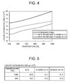
- FIG. 4 is a graph of a relationship between linear expansion coefficients and temperature of stainless steel and two kinds of heat-resistant Ni-base alloy A, B.
- FIG. 5 is a chart of linear expansion coefficients of stainless steel and two kinds of heat-resistant Ni-base alloy A, B at temperatures of 900°C and 1000°C. As illustrated in FIGs. 4 and 5 , the two kinds of heat-resistant Ni-base alloy A, B have linear expansion coefficients smaller than that of stainless steel. Also, from among the two kinds of heat-resistant Ni-base alloy A, B, the heat-resistant Ni-base alloy B has a linear expansion coefficient smaller than that of the heat-resistant Ni-base alloy A.
- a liner expansion coefficient is small means that a linear expansion coefficient is small when compared between two kinds of materials under a predetermined temperature condition during operation of an engine (for instance, 1000°C which is an exhaust gas temperature during operation of a gasoline engine).
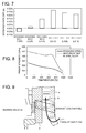
- FIG. 6 is a chart of differences (extension ratio differences) in the amount of thermal deformation between the nozzle mount 2 and the nozzle plate 4 in cases where stainless steel and two kinds of heat-resistant Ni-base alloy A, B having different linear expansion coefficients are used in the nozzle mount 2 and the nozzle plate 4.
- FIG. 7 is a graph of FIG. 6 .
- T1 is set to 1000°C and T2 is set to 900°C assuming that the variable-geometry exhaust turbocharger 1 is employed in a gasoline engine.
- the extension rate difference when using heat-resistant Ni-base alloy A for the nozzle plate 4 and stainless steel for the nozzle mount 2, the extension rate difference is minus 0.05% (the first working example). Further, when using heat-resistant Ni-base alloy B for the nozzle plate 4 and stainless steel for the nozzle mount 2, the extension rate difference is 0.02% (the second working example). Still further, when using heat-resistant Ni-base alloy A for the nozzle plate 4 and heat-resistant Ni-base alloy B for the nozzle mount 2, the extension rate difference is 0.14% (the third working example).
- the extension rate difference is 0.21% to 0.27% (the first to third reference examples).
- extension rate difference in order to reduce the difference (extension rate difference) in the amount of thermal deformation between the nozzle mount 2 and the nozzle plate 4 under a high-temperature condition to prevent a large shear force and bending moment from being applied to the nozzle supports 6, it is desirable to reduce the difference (extension rate difference) in the amount of thermal deformation between the nozzle mount 2 and the nozzle plate 4 to be small.
- a material may be selected for each of the nozzle mount 2 and the nozzle plate 4 so that the absolute value of the extension rate difference (A) is not greater than 0.20%.
- the nozzle plate 4 which is exposed to the exhaust gas at both sides so that the temperature rises higher, is formed of heat-resistant Ni-base alloy having a small linear expansion coefficient, while the nozzle mount 2 is formed of stainless steel which is relatively low cost. In this way, it is possible to reduce the difference (extension rate difference) in the amount of thermal deformation between the nozzle mount 2 and the nozzle plate 4 under a high-temperature condition and also to reduce the material cost.
- heat-resistant Ni-base alloy has high proof strength under a high-temperature condition as compared to stainless steel.
- the nozzle plate 4 and the nozzle mount 2 may be both formed of heat-resistant Ni-base alloy, using the heat-resistant Ni-base alloy A having a relatively small linear expansion coefficient for the nozzle plate 4 and the heat-resistant Ni-base alloy B having a relatively large linear expansion coefficient for the nozzle mount 2. In this way, it is possible to reduce the difference (extension rate difference) in the amount of thermal deformation between the nozzle mount 2 and the nozzle plate 4 under a high-temperature condition and to achieve a variable nozzle mechanism 10 with high heat-resistance.
- the nozzle supports 6 which are the cylindrical members for coupling the nozzle mount 2 and the nozzle plate 4 may be formed of heat-resistant Ni-base alloy. In this way, it is possible to achieve a variable nozzle mechanism 10 with high proof strength under a high-temperature condition.
- At least one embodiment of the present invention may be preferably used as a variable-geometry exhaust turbocharger used in an engine, preferably in a gasoline engine for a vehicle.
Landscapes
- Engineering & Computer Science (AREA)
- Mechanical Engineering (AREA)
- General Engineering & Computer Science (AREA)
- Chemical & Material Sciences (AREA)
- Combustion & Propulsion (AREA)
- Physics & Mathematics (AREA)
- Geometry (AREA)
- Supercharger (AREA)
- Control Of Turbines (AREA)
Description
- The present disclosure relates to a variable-geometry exhaust turbocharger including a variable nozzle mechanism.
- In an exhaust turbocharger used in a diesel engine of a vehicle, a variable nozzle mechanism is widely used. The variable nozzle mechanism is disposed between an exhaust gas channel of a scroll shape formed in a turbine housing and a turbine rotor rotatably disposed at the center of the turbine housing to control the flow of the exhaust gas acting on the turbine rotor.
- The variable nozzle mechanism includes a nozzle mount and a nozzle plate which are supported by nozzle supports and spaced from each other. A plurality of nozzle vanes are supported rotatably between the nozzle mount and the nozzle plate. The angle of the nozzle vanes is varied to control the flow of the exhaust gas flowing between the nozzle mount and the nozzle plate, and thereby the flow of the exhaust gas acting on the turbine rotor is controlled.
- For instance, Japanese Patent No.
4885118 - Patent Document 1: Japanese Patent No.
4885118 - The temperature of exhaust gas discharged from a diesel engine may increase as high as approximately 850°C, causing thermal deformation in a nozzle mount and a nozzle plate formed of stainless steel or the like. At this time, the amount of thermal deformation is varied between the nozzle mount and the nozzle plate because the nozzle mount contacts the high-temperature exhaust gas at only one face fixed to a bearing housing or the like while the nozzle plate is exposed to the high-temperature exhaust gas at both faces. As a result, a shear force or a bending moment may be applied to the nozzle supports 6 coupling the
nozzle plate 4 and thenozzle mount 2 as illustrated inFIG. 9 , thereby deforming thenozzle supports 6. -
FIG. 10 is a chart of linear expansion coefficients of stainless steel at temperatures of 850°C and 760°C.FIG. 11 is a chart of extension rates of stainless steel at temperatures of 850°C and 760°C, and an extension rate difference between the above temperatures. - An extension rate here means the amount of strain, α × ΔT, where ΔT is the amount of temperature change from the reference temperature To of a material, and α is the linear expansion coefficient.
- When the same kind of stainless steel having the same linear expansion coefficient illustrated in
FIG. 10 is used for thenozzle mount 2 and thenozzle plate 4, the nozzle plate has an extension rate of 1.56% at a temperature of 850°C while the nozzle mount has an extension rate of 1.34% at a temperature of 760°C as illustrated inFIG. 11 . The extension rate difference between the nozzle plate and the nozzle mount is 0.22%. The reference temperature To here is 20°C. - When employing a variable-geometry exhaust turbocharger including a variable nozzle mechanism in a gasoline engine in the future, the temperature of exhaust gas discharged from a gasoline engine is expected to be higher than 850°C, which further increases the above difference (extension rate difference) in the amount of thermal deformation between the nozzle mount and the nozzle plate. This may cause an even larger shear force and bending moment to be applied to the nozzle supports.
- At least one embodiment of the present invention was made in view of the above problem of the conventional technique to provide a variable-geometry exhaust turbocharger including a variable nozzle mechanism with a small difference in the amount of thermal deformation between the nozzle mount and the nozzle plate under a high-temperature condition, so that a large shear force or bending moment may not act on the nozzle supports to deform the nozzle supports.
- To achieve the above object, at least one embodiment of the present invention provides a variable-geometry exhaust turbocharger including: a nozzle mount fixed to a housing; a nozzle support having a first end coupled to a first face of the nozzle mount; a nozzle plate coupled to the second end of the nozzle support and supported to be separated from the first face of the nozzle mount, the nozzle plate having a first face coupled to the nozzle support and a second face which is opposite to the first face and which faces an exhaust gas channel through which exhaust gas flows; a plurality of nozzle vanes rotatably supported between the nozzle mount and the nozzle plate; and a variable nozzle mechanism configured to change vane angles of the nozzle vanes to control a flow of the exhaust gas flowing between the nozzle mount and the nozzle plate. The nozzle plate is formed of a material having a smaller linear expansion coefficient than that of a material forming the nozzle mount.
- In the variable-geometry exhaust turbocharger with the above configuration, the nozzle plate, which is exposed to the exhaust gas at both sides so that the temperature rises higher, is formed of a material having a smaller linear expansion coefficient than that of a material forming the nozzle mount. As a result, it is possible to reduce the difference in the amount of thermal deformation between the nozzle mount and the nozzle plate under a high-temperature condition as compared to a conventional variable-geometry exhaust turbocharger in which a nozzle mount and a nozzle plate are formed of the same material.
- Further, in the variable-geometry exhaust turbocharger according to one embodiment of the present invention, the nozzle plate is formed of heat-resistant Ni-base alloy, and the nozzle mount is formed of stainless steel.
- According to the variable-geometry exhaust turbocharger of the above embodiment, the nozzle plate, which is exposed to the exhaust gas at both sides so that the temperature rises higher, is formed of heat-resistant Ni-base alloy which has a small linear expansion coefficient, while the nozzle mount is formed of stainless steel which is relatively low cost. As a result, it is possible to reduce the difference in the amount of thermal deformation between the nozzle mount and the nozzle plate under a high-temperature condition and to reduce the material cost.
- Further, in the variable-geometry exhaust turbocharger according to one embodiment of the present invention, the nozzle plate and the nozzle mount are formed of different kinds of heat-resistant Ni-base alloy having different linear expansion coefficients.
- According to the variable-geometry exhaust turbocharger of the above embodiment, the nozzle plate is formed of heat-resistant Ni-base alloy having a relatively small linear expansion coefficient while the nozzle mount is formed of heat-resistant Ni-base alloy having a relatively large linear expansion coefficient. Thus, both of the nozzle plate and the nozzle mount are formed of heat-resistant Ni-base alloy, which makes it possible to reduce the difference in the amount of deformation between the nozzle plate and the nozzle mount, and to achieve a variable nozzle mechanism having high heat resistance.
- Further, in the variable-geometry exhaust turbocharger according to one embodiment of the present invention, the materials forming the nozzle plate and the nozzle mount are each selected so that an absolute value of an extension rate difference A defined by the following equation (1) is not greater than 0.20%:

where: α1 is a linear expansion coefficient of the material forming the nozzle plate; α2 is a linear expansion coefficient of the material forming the nozzle mount; T1 is a temperature of the nozzle plate during operation of an engine; T2 is a temperature of the nozzle mount during operation of the engine; and To is a reference temperature. - According to the variable-geometry exhaust turbocharger of the above embodiment, the materials forming the nozzle plate and the nozzle mount are each selected so that the absolute value of an extension rate difference A defined by the equation (1) is not greater than 0.20%. In this way, it is possible to provide a variable-geometry exhaust turbocharger including a variable nozzle mechanism in which the difference in the amount of thermal deformation between the nozzle mount and the nozzle plate under a high-temperature condition is small.
- A variable-geometry exhaust turbocharger according to one embodiment of the present invention described above may be suitably used in a gasoline engine in which the temperature of exhaust gas becomes high.
- According to at least one embodiment of the present invention, it is possible to provide a variable-geometry exhaust turbocharger including a variable nozzle mechanism in which the difference in the amount of thermal deformation between the nozzle mount and the nozzle plate under a high-temperature condition is small, and therefore a large shear force or bending moment may not be applied to the nozzle supports to deform the nozzle supports.
-
-
FIG. 1 is a cross-sectional view of a variable-geometry exhaust turbocharger according to one embodiment of the present invention. -
FIG. 2 is a cross-sectional view taken along line B-B ofFIG. 1 . -
FIG. 3 is a cross-sectional view taken along line A-A ofFIG. 2 . -
FIG. 4 is a graph of a relationship between linear expansion coefficients and temperature of stainless steel and heat-resistant Ni-base alloy A, B. -
FIG. 5 is a chart of linear expansion coefficients of stainless steel and two kinds of heat-resistant Ni-base alloy A, B at temperatures of 900°C and 1000°C. -
FIG. 6 is a chart of differences (extension ratio differences) in the amount of thermal deformation of a nozzle mount and a nozzle plate in cases where stainless steel and the heat-resistant Ni-base alloy A, B are used in the nozzle mount and the nozzle plate. -
FIG. 7 is a graph ofFIG. 6 . -
FIG. 8 is a graph of a relationship between proof strength and temperature of stainless steel and heat-resistant Ni-base alloy. -
FIG. 9 is a diagram of a state where a nozzle plate and a nozzle mount are deformed to extend, and a shear force or a bending moment is applied to nozzle supports which couple the nozzle plate and the nozzle mount. -
FIG. 10 is a chart of linear expansion coefficients of stainless steel at temperatures of 850°C and 760°C. -
FIG. 11 is a chart of extension rates of stainless steel at temperatures of 850°C and 760°C, and an extension rate difference between the temperatures. - Embodiments of the present invention will now be described in detail with reference to the accompanying drawings. It is intended, however, that unless particularly specified, dimensions, materials, shapes, relative positions and the like of components described in the embodiments shall be interpreted as illustrative only and not limitative of the scope of the present invention.
-
FIG. 1 is a cross-sectional view of a variable-geometry exhaust turbocharger according to one embodiment of the present invention.FIG. 2 is a cross-sectional view taken along line B-B ofFIG. 1 .FIG. 3 is a cross-sectional view taken along line A-A ofFIG. 2 . First, the basic configuration of avariable nozzle mechanism 10 of a variable-geometry exhaust turbocharger 1 according to one embodiment of the present invention will be described in reference toFIGs. 1 to 3 . - As illustrated in
FIG. 1 , the variable-geometry exhaust turbocharger 1 according to one embodiment of the present invention includes aturbine housing 16 for accommodating aturbine rotor 12, and a bearinghousing 18 for accommodating abearing 22 rotatably supporting arotational shaft 12a of theturbine rotor 12. The turbine housing 16 and the bearinghousing 18 are fastened to each other via bolts, for instance. Although not illustrated, a compressor housing for accommodating a compressor rotor coupled to therotational shaft 12a is coupled to the bearinghousing 18 at the opposite side of theturbine housing 16 across the bearinghousing 18. - On the outer circumferential side of the turbine housing 16, an
exhaust gas channel 20 of a scroll shape is formed. Theexhaust gas channel 20 communicates with an exhaust-gas manifold (not illustrated), and exhaust gas discharged from an engine flows through theexhaust gas channel 20. Further, avariable nozzle mechanism 10 for controlling the flow of the exhaust gas acting on theturbine rotor 12 is disposed between theexhaust gas channel 20 of a scroll shape and theturbine rotor 12. - As illustrated in
FIG. 1 , thevariable nozzle mechanism 10 is fixed to the bearinghousing 18 by thenozzle mount 2 being fastened to the bearinghousing 18 by bolts or the like while thevariable nozzle mechanism 10 is interposed between theturbine housing 16 and the bearinghousing 18. Also, as illustrated inFIG. 3 , thevariable nozzle mechanism 10 includes a plurality of nozzle supports 6 each of which is a cylindrical member and has the first end coupled to afirst face 2a of thenozzle mount 2. Moreover, thefirst face 4a of thenozzle plate 4 is coupled to the second end of eachnozzle support 6. The plurality of nozzle supports 6 are coupled to thefirst face 2a of thenozzle mount 2 and to thefirst face 4a of thenozzle plate 4 in a circumferential fashion in the planar view. In this way, thenozzle plate 4 is supported at a position spaced away from thefirst face 2a of thenozzle mount 2. - As illustrated in
FIGs. 2 and 3 , adrive ring 5 formed into a disc-like shape is disposed rotatably on thesecond face 2b of thenozzle mount 2. An end of eachlever plate 3 is coupled to thedrive ring 5. The opposite end of eachlever plate 3 is coupled to anozzle vane 8 via anozzle shaft 8a, so that eachlever plate 3 rotates and the vane angle of eachnozzle vane 8 varies in response to rotation of thedrive ring 5. - In the variable-
geometry exhaust turbocharger 1 including thevariable nozzle mechanism 10 with the above configuration, the exhaust gas having flowed through theexhaust gas channel 20 of a scroll shape flows into a gap between thenozzle mount 2 and thenozzle plate 4, and then to the central portion of theturbine housing 16 as thenozzle vanes 8 control the flow direction, as indicated by the arrow "f" ofFIG. 1 . Then, after acting on theturbine rotor 12, the exhaust gas is discharged to the outside from theexhaust gas outlet 24. - act this point, as illustrated in
FIG. 1 , thenozzle plate 4 is disposed so that thesecond face 4b, disposed on the opposite side of thefirst face 4a to which the nozzle supports 8 are coupled, faces theexhaust gas channel 20 thorough which the exhaust gas flows. That is, thenozzle plate 4 is exposed to the exhaust gas at both of thefirst face 4a and thesecond face 4b. In contrast, thenozzle mount 2 is in contact with the exhaust gas only at thefirst face 2a, so that thesecond face 2b is oriented to face the bearinghousing 18 side and not exposed to the exhaust gas. - As described above, since the
nozzle plate 4 is exposed to the exhaust gas at bothfaces nozzle mount 2 is in contact with the exhaust gas only at thefirst face 2a, the temperature of thenozzle plate 4 becomes higher than that of thenozzle mount 2 while the engine is in operation. According to the research of the inventors, the temperature of thenozzle plate 4 rises as high as 850°C in the case of a diesel engine with the exhaust gas temperature of approximately 850°C, while the temperature of thenozzle mount 2 only rises to 760°C. Further, in the case of a gasoline engine with the exhaust gas temperature of approximately 1000°C, the temperature of thenozzle plate 4 rises as high as 1000°C while the temperature of thenozzle mount 2 only rises to 850°C. - When the
nozzle mount 2 and thenozzle plate 4 have different temperatures as described above, a shear force or a bending moment acts on thenozzle support 6 coupling thenozzle mount 2 and thenozzle plate 4 under a high-temperature condition due to the difference in the amount of thermal deformation between thenozzle mount 2 and thenozzle plate 4, thereby possibly deforming thenozzle support 6. Thus, in at least one embodiment of the present invention, thenozzle plate 4 is formed of a material having a linear expansion coefficient smaller than that of a material forming thenozzle mount 2 so as to reduce the difference between the amount of thermal deformation between thenozzle mount 2 and thenozzle plate 4 under a high-temperature condition as will be described below. - In one embodiment of the present invention, as materials of the
nozzle mount 2 and thenozzle plate 4, stainless steel and heat-resistance Ni-base alloy including Inconel (Registered trademark) such asInconel 600, Inconel 625, Inconel 718, and Inconel 750X and Hastelloy (Registered trademark) such as Hastelloy C22, Hastelloy C276, and Hastelloy B may be used suitably. -
FIG. 4 is a graph of a relationship between linear expansion coefficients and temperature of stainless steel and two kinds of heat-resistant Ni-base alloy A, B.FIG. 5 is a chart of linear expansion coefficients of stainless steel and two kinds of heat-resistant Ni-base alloy A, B at temperatures of 900°C and 1000°C. As illustrated inFIGs. 4 and 5 , the two kinds of heat-resistant Ni-base alloy A, B have linear expansion coefficients smaller than that of stainless steel. Also, from among the two kinds of heat-resistant Ni-base alloy A, B, the heat-resistant Ni-base alloy B has a linear expansion coefficient smaller than that of the heat-resistant Ni-base alloy A. In the present description, "a liner expansion coefficient is small" means that a linear expansion coefficient is small when compared between two kinds of materials under a predetermined temperature condition during operation of an engine (for instance, 1000°C which is an exhaust gas temperature during operation of a gasoline engine). -
FIG. 6 is a chart of differences (extension ratio differences) in the amount of thermal deformation between thenozzle mount 2 and thenozzle plate 4 in cases where stainless steel and two kinds of heat-resistant Ni-base alloy A, B having different linear expansion coefficients are used in thenozzle mount 2 and thenozzle plate 4.FIG. 7 is a graph ofFIG. 6 . - Here, the extension rate difference (A) is calculated by the following equation (1):

where: - α1 is the linear expansion coefficient of a material forming the
nozzle plate 4; - α2 is the linear expansion coefficient of a material forming the
nozzle mount 2; - T1 is the temperature of the
nozzle plate 4 during operation of the engine; - T2 is the temperature of the
nozzle mount 2 during operation of the engine; and - To is the reference temperature (20°C herein).
- Also, in
FIGs. 6 and7 , T1 is set to 1000°C and T2 is set to 900°C assuming that the variable-geometry exhaust turbocharger 1 is employed in a gasoline engine. - As illustrated in
FIGs. 6 and7 , when using heat-resistant Ni-base alloy A for thenozzle plate 4 and stainless steel for thenozzle mount 2, the extension rate difference is minus 0.05% (the first working example). Further, when using heat-resistant Ni-base alloy B for thenozzle plate 4 and stainless steel for thenozzle mount 2, the extension rate difference is 0.02% (the second working example). Still further, when using heat-resistant Ni-base alloy A for thenozzle plate 4 and heat-resistant Ni-base alloy B for thenozzle mount 2, the extension rate difference is 0.14% (the third working example). - On the other hand, when the same material having the same linear expansion coefficient is used for the
nozzle mount 2 and thenozzle plate 4, the extension rate difference is 0.21% to 0.27% (the first to third reference examples). - In order to reduce the difference (extension rate difference) in the amount of thermal deformation between the
nozzle mount 2 and thenozzle plate 4 under a high-temperature condition to prevent a large shear force and bending moment from being applied to the nozzle supports 6, it is desirable to reduce the difference (extension rate difference) in the amount of thermal deformation between thenozzle mount 2 and thenozzle plate 4 to be small. Preferably, in order to reduce the extension rate difference (A) to a value approximately not greater than the conventional value (seeFIG. 11 ), a material may be selected for each of thenozzle mount 2 and thenozzle plate 4 so that the absolute value of the extension rate difference (A) is not greater than 0.20%. - Further, as illustrated in the first and second working examples, the
nozzle plate 4, which is exposed to the exhaust gas at both sides so that the temperature rises higher, is formed of heat-resistant Ni-base alloy having a small linear expansion coefficient, while thenozzle mount 2 is formed of stainless steel which is relatively low cost. In this way, it is possible to reduce the difference (extension rate difference) in the amount of thermal deformation between thenozzle mount 2 and thenozzle plate 4 under a high-temperature condition and also to reduce the material cost. - Further, as illustrated in
FIG. 8 , heat-resistant Ni-base alloy has high proof strength under a high-temperature condition as compared to stainless steel. Thus, as illustrated in the third working example, thenozzle plate 4 and thenozzle mount 2 may be both formed of heat-resistant Ni-base alloy, using the heat-resistant Ni-base alloy A having a relatively small linear expansion coefficient for thenozzle plate 4 and the heat-resistant Ni-base alloy B having a relatively large linear expansion coefficient for thenozzle mount 2. In this way, it is possible to reduce the difference (extension rate difference) in the amount of thermal deformation between thenozzle mount 2 and thenozzle plate 4 under a high-temperature condition and to achieve avariable nozzle mechanism 10 with high heat-resistance. - Further, in one embodiment of the present invention, the nozzle supports 6 which are the cylindrical members for coupling the
nozzle mount 2 and thenozzle plate 4 may be formed of heat-resistant Ni-base alloy. In this way, it is possible to achieve avariable nozzle mechanism 10 with high proof strength under a high-temperature condition. - Embodiments of the present invention were described in detail above, but the present invention is not limited thereto, and various amendments and modifications may be implemented within a scope that does not depart from the present invention.
- At least one embodiment of the present invention may be preferably used as a variable-geometry exhaust turbocharger used in an engine, preferably in a gasoline engine for a vehicle.
-
- 1
- Variable-geometry exhaust turbocharger
- 2
- Nozzle mount
- 3
- Lever plate
- 4
- Nozzle plate
- 5
- Drive ring
- 6
- Nozzle support
- 8
- Nozzle vane
- 8a
- Nozzle shaft
- 10
- Variable nozzle mechanism
- 12
- Turbine rotor
- 12a
- Rotational shaft
- 16
- Turbine housing
- 18
- Bearing housing
- 20
- Exhaust gas channel
- 22
- Bearing
- 24
- Exhaust-gas outlet
Claims (5)
- A variable-geometry exhaust turbocharger, comprising:a nozzle mount fixed to a housing;a nozzle support having a first end coupled to a first face of the nozzle mount;a nozzle plate coupled to the second end of the nozzle support and supported to be separated from the first face of the nozzle mount, the nozzle plate having a first face coupled to the nozzle support and a second face which is opposite to the first face and which faces an exhaust gas channel through which exhaust gas flows;a plurality of nozzle vanes rotatably supported between the nozzle mount and the nozzle plate; anda variable nozzle mechanism configured to change vane angles of the nozzle vanes to control a flow of the exhaust gas flowing between the nozzle mount and the nozzle plate,wherein the nozzle plate is formed of a material having a smaller linear expansion coefficient than that of a material forming the nozzle mount.
- The variable-geometry exhaust turbocharger according to claim 1,
wherein the nozzle plate is formed of heat-resistant Ni-base alloy, and
wherein the nozzle mount is formed of stainless steel. - The variable-geometry exhaust turbocharger according to claim 1,
wherein the nozzle plate and the nozzle mount are formed of different kinds of heat-resistant Ni-base alloy having different linear expansion coefficients. - The variable-geometry exhaust turbocharger according to any one of claims 1 to 3,
wherein the materials forming the nozzle plate and the nozzle mount are each selected so that an absolute value of an extension rate difference A defined by the following equation (1) is not greater than 0.20%:
where:α1 is a linear expansion coefficient of the material forming the nozzle plate;α2 is a linear expansion coefficient of the material forming the nozzle mount;T1 is a temperature of the nozzle plate during operation of an engine;T2 is a temperature of the nozzle mount during operation of the engine; andT is a reference temperature. - The variable-geometry exhaust turbocharger according to any one of claims 1 to 4,
wherein the variable-geometry exhaust turbocharger is used in a gasoline engine.
Applications Claiming Priority (2)
| Application Number | Priority Date | Filing Date | Title |
|---|---|---|---|
| JP2012175801A JP6037712B2 (en) | 2012-08-08 | 2012-08-08 | Variable displacement exhaust turbocharger |
| PCT/JP2013/071320 WO2014024905A1 (en) | 2012-08-08 | 2013-08-07 | Variable-capacity exhaust turbosupercharger |
Publications (3)
| Publication Number | Publication Date |
|---|---|
| EP2884073A1 true EP2884073A1 (en) | 2015-06-17 |
| EP2884073A4 EP2884073A4 (en) | 2015-10-14 |
| EP2884073B1 EP2884073B1 (en) | 2017-04-19 |
Family
ID=50068129
Family Applications (1)
| Application Number | Title | Priority Date | Filing Date |
|---|---|---|---|
| EP13827476.6A Active EP2884073B1 (en) | 2012-08-08 | 2013-08-07 | Variable-capacity exhaust turbosupercharger |
Country Status (5)
| Country | Link |
|---|---|
| US (1) | US9822784B2 (en) |
| EP (1) | EP2884073B1 (en) |
| JP (1) | JP6037712B2 (en) |
| CN (1) | CN104487675B (en) |
| WO (1) | WO2014024905A1 (en) |
Families Citing this family (16)
| Publication number | Priority date | Publication date | Assignee | Title |
|---|---|---|---|---|
| JP6476615B2 (en) | 2014-07-04 | 2019-03-06 | 株式会社Ihi | Variable nozzle unit and variable capacity turbocharger |
| EP3169876B1 (en) | 2014-07-16 | 2019-03-06 | Borgwarner Inc. | Adjustment ring assembly for variable turbine geometry turbochargers |
| US10393009B2 (en) * | 2016-04-19 | 2019-08-27 | Garrett Transportation I Inc. | Adjustable-trim centrifugal compressor for a turbocharger |
| DE102016125189B4 (en) * | 2016-12-21 | 2020-11-26 | Man Energy Solutions Se | turbocharger |
| CN109563769B (en) * | 2017-03-16 | 2021-04-27 | 三菱重工业株式会社 | Variable Nozzle Unit and Variable Capacity Exhaust Turbocharger |
| DE102017208107A1 (en) * | 2017-05-15 | 2018-11-15 | Man Diesel & Turbo Se | turbocharger |
| JP6651599B2 (en) * | 2017-11-30 | 2020-02-19 | 三菱重工業株式会社 | Variable nozzle mechanism and rotating machine equipped with the same |
| CN111630258B (en) | 2018-03-05 | 2022-05-31 | 三菱重工发动机和增压器株式会社 | Turbochargers and Internal Combustion Engines |
| CN110657108B (en) * | 2018-06-28 | 2022-10-28 | 丹佛斯公司 | Variable stage compressor |
| WO2020012731A1 (en) | 2018-07-11 | 2020-01-16 | 株式会社Ihi | Supercharger |
| DE112019006906B4 (en) * | 2019-03-28 | 2025-12-18 | Mitsubishi Heavy Industries Engine & Turbocharger, Ltd. | NOZZLE DEVICE AND EXHAUST TURBOCHARGER |
| US10927702B1 (en) | 2019-03-30 | 2021-02-23 | Savant Holdings LLC | Turbocharger or turbocharger component |
| AU2020351235A1 (en) | 2019-09-18 | 2022-03-24 | Massachusetts Institute Of Technology | Adaptive volutes for centrifugal pumps |
| WO2022144995A1 (en) * | 2020-12-28 | 2022-07-07 | 三菱重工エンジン&ターボチャージャ株式会社 | Nozzle component, variable nozzle mechanism for variable-capacity turbocharger, variable-capacity turbocharger, and method for manufacturing nozzle component |
| CN119053772A (en) * | 2022-05-25 | 2024-11-29 | 株式会社Ihi | Turbine and supercharger |
| CN120712400A (en) * | 2023-03-31 | 2025-09-26 | 三菱重工发动机和增压器株式会社 | Variable nozzle device and variable capacity exhaust turbocharger |
Family Cites Families (12)
| Publication number | Priority date | Publication date | Assignee | Title |
|---|---|---|---|---|
| JPS6357329U (en) | 1986-10-03 | 1988-04-16 | ||
| JPH10103070A (en) * | 1996-09-27 | 1998-04-21 | Toyota Motor Corp | Variable capacity turbocharger |
| JP2001289050A (en) * | 1999-05-20 | 2001-10-19 | Hitachi Ltd | Variable capacity turbocharger |
| JP4885118B2 (en) * | 2007-12-21 | 2012-02-29 | 三菱重工業株式会社 | Variable displacement exhaust turbocharger with variable nozzle mechanism |
| DE102008014680A1 (en) | 2008-03-18 | 2010-09-23 | Continental Automotive Gmbh | Leitgitteranordnung an exhaust gas turbocharger, exhaust gas turbocharger and method for producing a Leitgitteranordnung |
| JP5100487B2 (en) * | 2008-04-25 | 2012-12-19 | 日立粉末冶金株式会社 | Manufacturing method of sintered machine parts |
| JP2009281295A (en) * | 2008-05-22 | 2009-12-03 | Toyota Motor Corp | Variable displacement type turbocharger |
| JP5452991B2 (en) | 2008-07-10 | 2014-03-26 | ボーグワーナー インコーポレーテッド | Variable geometry vane ring assembly with stepped spacers |
| DE102009005938A1 (en) * | 2009-01-23 | 2010-07-29 | Bosch Mahle Turbo Systems Gmbh & Co. Kg | loader |
| JP5101546B2 (en) * | 2009-02-26 | 2012-12-19 | 三菱重工業株式会社 | Variable displacement exhaust turbocharger |
| JP5010712B2 (en) | 2010-05-14 | 2012-08-29 | 三菱重工業株式会社 | Variable displacement exhaust turbocharger and variable nozzle mechanism component manufacturing method |
| JP5868598B2 (en) * | 2010-08-05 | 2016-02-24 | 日本ピストンリング株式会社 | Turbocharger parts and method of manufacturing turbocharger parts |
-
2012
- 2012-08-08 JP JP2012175801A patent/JP6037712B2/en not_active Expired - Fee Related
-
2013
- 2013-08-07 EP EP13827476.6A patent/EP2884073B1/en active Active
- 2013-08-07 CN CN201380039297.6A patent/CN104487675B/en active Active
- 2013-08-07 WO PCT/JP2013/071320 patent/WO2014024905A1/en not_active Ceased
- 2013-08-07 US US14/418,368 patent/US9822784B2/en not_active Expired - Fee Related
Also Published As
| Publication number | Publication date |
|---|---|
| JP6037712B2 (en) | 2016-12-07 |
| EP2884073B1 (en) | 2017-04-19 |
| CN104487675B (en) | 2017-11-14 |
| JP2014034910A (en) | 2014-02-24 |
| US20150211538A1 (en) | 2015-07-30 |
| WO2014024905A1 (en) | 2014-02-13 |
| CN104487675A (en) | 2015-04-01 |
| EP2884073A4 (en) | 2015-10-14 |
| US9822784B2 (en) | 2017-11-21 |
Similar Documents
| Publication | Publication Date | Title |
|---|---|---|
| EP2884073B1 (en) | Variable-capacity exhaust turbosupercharger | |
| US11313242B2 (en) | Thin seal for an engine | |
| EP2960461B1 (en) | Variable capacity exhaust turbine | |
| EP1998006B1 (en) | Retention system for an inlet guide vane | |
| CA2907233C (en) | Apparatus and system for ceramic matrix composite attachment | |
| EP3489483B1 (en) | Variable nozzle device and variable capacity-type exhaust turbocharger | |
| EP2233718B1 (en) | Turbocharger | |
| EP3249171A2 (en) | Seal assembly | |
| CN104975886A (en) | Vane carrier for compressor or turbine section of axial turbo machine | |
| US7762768B2 (en) | Mechanical support of a ceramic gas turbine vane ring | |
| EP3173599A1 (en) | Variable nozzle mechanism and variable displacement turbocharger | |
| EP3744955A1 (en) | Turbo-supercharger and internal-combustion engine | |
| US12116896B1 (en) | Seal support assembly for a turbine engine | |
| US12215587B2 (en) | Seal support assembly for a turbine engine | |
| US12372002B2 (en) | Seal support assembly for a turbine engine | |
| US12421861B2 (en) | Seal support assembly for a turbine engine | |
| US12241375B2 (en) | Seal support assembly for a turbine engine | |
| US12416243B2 (en) | Seal support assembly for a turbine engine | |
| US12595745B2 (en) | Seal support assembly for a turbine engine | |
| US20250297555A1 (en) | Seal support assembly for a turbine engine | |
| CN118686665A (en) | Seal support assembly for turbine engines |
Legal Events
| Date | Code | Title | Description |
|---|---|---|---|
| PUAI | Public reference made under article 153(3) epc to a published international application that has entered the european phase |
Free format text: ORIGINAL CODE: 0009012 |
|
| 17P | Request for examination filed |
Effective date: 20150121 |
|
| AK | Designated contracting states |
Kind code of ref document: A1 Designated state(s): AL AT BE BG CH CY CZ DE DK EE ES FI FR GB GR HR HU IE IS IT LI LT LU LV MC MK MT NL NO PL PT RO RS SE SI SK SM TR |
|
| AX | Request for extension of the european patent |
Extension state: BA ME |
|
| RA4 | Supplementary search report drawn up and despatched (corrected) |
Effective date: 20150916 |
|
| RIC1 | Information provided on ipc code assigned before grant |
Ipc: F04D 29/02 20060101ALI20150910BHEP Ipc: F02M 25/07 20060101ALI20150910BHEP Ipc: F01D 17/16 20060101ALI20150910BHEP Ipc: F04D 19/02 20060101ALI20150910BHEP Ipc: F02B 37/24 20060101ALI20150910BHEP Ipc: F02B 39/00 20060101AFI20150910BHEP Ipc: F04D 27/00 20060101ALI20150910BHEP |
|
| DAX | Request for extension of the european patent (deleted) | ||
| RIC1 | Information provided on ipc code assigned before grant |
Ipc: F02M 26/00 20160101ALI20160721BHEP Ipc: F04D 29/02 20060101ALI20160721BHEP Ipc: F04D 19/02 20060101ALI20160721BHEP Ipc: F01D 17/16 20060101ALI20160721BHEP Ipc: F02B 39/00 20060101AFI20160721BHEP Ipc: F04D 27/00 20060101ALI20160721BHEP Ipc: F02B 37/24 20060101ALI20160721BHEP |
|
| GRAP | Despatch of communication of intention to grant a patent |
Free format text: ORIGINAL CODE: EPIDOSNIGR1 |
|
| INTG | Intention to grant announced |
Effective date: 20161010 |
|
| GRAS | Grant fee paid |
Free format text: ORIGINAL CODE: EPIDOSNIGR3 |
|
| GRAJ | Information related to disapproval of communication of intention to grant by the applicant or resumption of examination proceedings by the epo deleted |
Free format text: ORIGINAL CODE: EPIDOSDIGR1 |
|
| GRAL | Information related to payment of fee for publishing/printing deleted |
Free format text: ORIGINAL CODE: EPIDOSDIGR3 |
|
| INTC | Intention to grant announced (deleted) | ||
| GRAP | Despatch of communication of intention to grant a patent |
Free format text: ORIGINAL CODE: EPIDOSNIGR1 |
|
| INTG | Intention to grant announced |
Effective date: 20170217 |
|
| GRAA | (expected) grant |
Free format text: ORIGINAL CODE: 0009210 |
|
| AK | Designated contracting states |
Kind code of ref document: B1 Designated state(s): AL AT BE BG CH CY CZ DE DK EE ES FI FR GB GR HR HU IE IS IT LI LT LU LV MC MK MT NL NO PL PT RO RS SE SI SK SM TR |
|
| REG | Reference to a national code |
Ref country code: GB Ref legal event code: FG4D |
|
| REG | Reference to a national code |
Ref country code: CH Ref legal event code: EP |
|
| REG | Reference to a national code |
Ref country code: AT Ref legal event code: REF Ref document number: 886205 Country of ref document: AT Kind code of ref document: T Effective date: 20170515 |
|
| REG | Reference to a national code |
Ref country code: IE Ref legal event code: FG4D |
|
| REG | Reference to a national code |
Ref country code: DE Ref legal event code: R096 Ref document number: 602013020140 Country of ref document: DE |
|
| REG | Reference to a national code |
Ref country code: NL Ref legal event code: FP |
|
| REG | Reference to a national code |
Ref country code: FR Ref legal event code: PLFP Year of fee payment: 5 |
|
| REG | Reference to a national code |
Ref country code: LT Ref legal event code: MG4D |
|
| REG | Reference to a national code |
Ref country code: AT Ref legal event code: MK05 Ref document number: 886205 Country of ref document: AT Kind code of ref document: T Effective date: 20170419 |
|
| PG25 | Lapsed in a contracting state [announced via postgrant information from national office to epo] |
Ref country code: FI Free format text: LAPSE BECAUSE OF FAILURE TO SUBMIT A TRANSLATION OF THE DESCRIPTION OR TO PAY THE FEE WITHIN THE PRESCRIBED TIME-LIMIT Effective date: 20170419 Ref country code: HR Free format text: LAPSE BECAUSE OF FAILURE TO SUBMIT A TRANSLATION OF THE DESCRIPTION OR TO PAY THE FEE WITHIN THE PRESCRIBED TIME-LIMIT Effective date: 20170419 Ref country code: AT Free format text: LAPSE BECAUSE OF FAILURE TO SUBMIT A TRANSLATION OF THE DESCRIPTION OR TO PAY THE FEE WITHIN THE PRESCRIBED TIME-LIMIT Effective date: 20170419 Ref country code: GR Free format text: LAPSE BECAUSE OF FAILURE TO SUBMIT A TRANSLATION OF THE DESCRIPTION OR TO PAY THE FEE WITHIN THE PRESCRIBED TIME-LIMIT Effective date: 20170720 Ref country code: NO Free format text: LAPSE BECAUSE OF FAILURE TO SUBMIT A TRANSLATION OF THE DESCRIPTION OR TO PAY THE FEE WITHIN THE PRESCRIBED TIME-LIMIT Effective date: 20170719 Ref country code: LT Free format text: LAPSE BECAUSE OF FAILURE TO SUBMIT A TRANSLATION OF THE DESCRIPTION OR TO PAY THE FEE WITHIN THE PRESCRIBED TIME-LIMIT Effective date: 20170419 Ref country code: ES Free format text: LAPSE BECAUSE OF FAILURE TO SUBMIT A TRANSLATION OF THE DESCRIPTION OR TO PAY THE FEE WITHIN THE PRESCRIBED TIME-LIMIT Effective date: 20170419 |
|
| PG25 | Lapsed in a contracting state [announced via postgrant information from national office to epo] |
Ref country code: PL Free format text: LAPSE BECAUSE OF FAILURE TO SUBMIT A TRANSLATION OF THE DESCRIPTION OR TO PAY THE FEE WITHIN THE PRESCRIBED TIME-LIMIT Effective date: 20170419 Ref country code: IS Free format text: LAPSE BECAUSE OF FAILURE TO SUBMIT A TRANSLATION OF THE DESCRIPTION OR TO PAY THE FEE WITHIN THE PRESCRIBED TIME-LIMIT Effective date: 20170819 Ref country code: RS Free format text: LAPSE BECAUSE OF FAILURE TO SUBMIT A TRANSLATION OF THE DESCRIPTION OR TO PAY THE FEE WITHIN THE PRESCRIBED TIME-LIMIT Effective date: 20170419 Ref country code: BG Free format text: LAPSE BECAUSE OF FAILURE TO SUBMIT A TRANSLATION OF THE DESCRIPTION OR TO PAY THE FEE WITHIN THE PRESCRIBED TIME-LIMIT Effective date: 20170719 Ref country code: LV Free format text: LAPSE BECAUSE OF FAILURE TO SUBMIT A TRANSLATION OF THE DESCRIPTION OR TO PAY THE FEE WITHIN THE PRESCRIBED TIME-LIMIT Effective date: 20170419 Ref country code: SE Free format text: LAPSE BECAUSE OF FAILURE TO SUBMIT A TRANSLATION OF THE DESCRIPTION OR TO PAY THE FEE WITHIN THE PRESCRIBED TIME-LIMIT Effective date: 20170419 |
|
| REG | Reference to a national code |
Ref country code: DE Ref legal event code: R097 Ref document number: 602013020140 Country of ref document: DE |
|
| PG25 | Lapsed in a contracting state [announced via postgrant information from national office to epo] |
Ref country code: CZ Free format text: LAPSE BECAUSE OF FAILURE TO SUBMIT A TRANSLATION OF THE DESCRIPTION OR TO PAY THE FEE WITHIN THE PRESCRIBED TIME-LIMIT Effective date: 20170419 Ref country code: EE Free format text: LAPSE BECAUSE OF FAILURE TO SUBMIT A TRANSLATION OF THE DESCRIPTION OR TO PAY THE FEE WITHIN THE PRESCRIBED TIME-LIMIT Effective date: 20170419 Ref country code: DK Free format text: LAPSE BECAUSE OF FAILURE TO SUBMIT A TRANSLATION OF THE DESCRIPTION OR TO PAY THE FEE WITHIN THE PRESCRIBED TIME-LIMIT Effective date: 20170419 Ref country code: SK Free format text: LAPSE BECAUSE OF FAILURE TO SUBMIT A TRANSLATION OF THE DESCRIPTION OR TO PAY THE FEE WITHIN THE PRESCRIBED TIME-LIMIT Effective date: 20170419 Ref country code: RO Free format text: LAPSE BECAUSE OF FAILURE TO SUBMIT A TRANSLATION OF THE DESCRIPTION OR TO PAY THE FEE WITHIN THE PRESCRIBED TIME-LIMIT Effective date: 20170419 |
|
| PLBE | No opposition filed within time limit |
Free format text: ORIGINAL CODE: 0009261 |
|
| STAA | Information on the status of an ep patent application or granted ep patent |
Free format text: STATUS: NO OPPOSITION FILED WITHIN TIME LIMIT |
|
| PG25 | Lapsed in a contracting state [announced via postgrant information from national office to epo] |
Ref country code: IT Free format text: LAPSE BECAUSE OF FAILURE TO SUBMIT A TRANSLATION OF THE DESCRIPTION OR TO PAY THE FEE WITHIN THE PRESCRIBED TIME-LIMIT Effective date: 20170419 Ref country code: SM Free format text: LAPSE BECAUSE OF FAILURE TO SUBMIT A TRANSLATION OF THE DESCRIPTION OR TO PAY THE FEE WITHIN THE PRESCRIBED TIME-LIMIT Effective date: 20170419 |
|
| 26N | No opposition filed |
Effective date: 20180122 |
|
| REG | Reference to a national code |
Ref country code: CH Ref legal event code: PL |
|
| PG25 | Lapsed in a contracting state [announced via postgrant information from national office to epo] |
Ref country code: MC Free format text: LAPSE BECAUSE OF FAILURE TO SUBMIT A TRANSLATION OF THE DESCRIPTION OR TO PAY THE FEE WITHIN THE PRESCRIBED TIME-LIMIT Effective date: 20170419 |
|
| PG25 | Lapsed in a contracting state [announced via postgrant information from national office to epo] |
Ref country code: LI Free format text: LAPSE BECAUSE OF NON-PAYMENT OF DUE FEES Effective date: 20170831 Ref country code: CH Free format text: LAPSE BECAUSE OF NON-PAYMENT OF DUE FEES Effective date: 20170831 |
|
| REG | Reference to a national code |
Ref country code: IE Ref legal event code: MM4A |
|
| PG25 | Lapsed in a contracting state [announced via postgrant information from national office to epo] |
Ref country code: SI Free format text: LAPSE BECAUSE OF FAILURE TO SUBMIT A TRANSLATION OF THE DESCRIPTION OR TO PAY THE FEE WITHIN THE PRESCRIBED TIME-LIMIT Effective date: 20170419 |
|
| REG | Reference to a national code |
Ref country code: BE Ref legal event code: MM Effective date: 20170831 |
|
| PG25 | Lapsed in a contracting state [announced via postgrant information from national office to epo] |
Ref country code: LU Free format text: LAPSE BECAUSE OF NON-PAYMENT OF DUE FEES Effective date: 20170807 |
|
| REG | Reference to a national code |
Ref country code: FR Ref legal event code: PLFP Year of fee payment: 6 |
|
| PG25 | Lapsed in a contracting state [announced via postgrant information from national office to epo] |
Ref country code: IE Free format text: LAPSE BECAUSE OF NON-PAYMENT OF DUE FEES Effective date: 20170807 |
|
| PG25 | Lapsed in a contracting state [announced via postgrant information from national office to epo] |
Ref country code: BE Free format text: LAPSE BECAUSE OF NON-PAYMENT OF DUE FEES Effective date: 20170831 |
|
| PG25 | Lapsed in a contracting state [announced via postgrant information from national office to epo] |
Ref country code: MT Free format text: LAPSE BECAUSE OF NON-PAYMENT OF DUE FEES Effective date: 20170807 |
|
| PG25 | Lapsed in a contracting state [announced via postgrant information from national office to epo] |
Ref country code: HU Free format text: LAPSE BECAUSE OF FAILURE TO SUBMIT A TRANSLATION OF THE DESCRIPTION OR TO PAY THE FEE WITHIN THE PRESCRIBED TIME-LIMIT; INVALID AB INITIO Effective date: 20130807 |
|
| PG25 | Lapsed in a contracting state [announced via postgrant information from national office to epo] |
Ref country code: CY Free format text: LAPSE BECAUSE OF FAILURE TO SUBMIT A TRANSLATION OF THE DESCRIPTION OR TO PAY THE FEE WITHIN THE PRESCRIBED TIME-LIMIT Effective date: 20170419 |
|
| PG25 | Lapsed in a contracting state [announced via postgrant information from national office to epo] |
Ref country code: MK Free format text: LAPSE BECAUSE OF FAILURE TO SUBMIT A TRANSLATION OF THE DESCRIPTION OR TO PAY THE FEE WITHIN THE PRESCRIBED TIME-LIMIT Effective date: 20170419 |
|
| PG25 | Lapsed in a contracting state [announced via postgrant information from national office to epo] |
Ref country code: TR Free format text: LAPSE BECAUSE OF FAILURE TO SUBMIT A TRANSLATION OF THE DESCRIPTION OR TO PAY THE FEE WITHIN THE PRESCRIBED TIME-LIMIT Effective date: 20170419 |
|
| PG25 | Lapsed in a contracting state [announced via postgrant information from national office to epo] |
Ref country code: PT Free format text: LAPSE BECAUSE OF FAILURE TO SUBMIT A TRANSLATION OF THE DESCRIPTION OR TO PAY THE FEE WITHIN THE PRESCRIBED TIME-LIMIT Effective date: 20170419 |
|
| PG25 | Lapsed in a contracting state [announced via postgrant information from national office to epo] |
Ref country code: AL Free format text: LAPSE BECAUSE OF FAILURE TO SUBMIT A TRANSLATION OF THE DESCRIPTION OR TO PAY THE FEE WITHIN THE PRESCRIBED TIME-LIMIT Effective date: 20170419 |
|
| PGFP | Annual fee paid to national office [announced via postgrant information from national office to epo] |
Ref country code: NL Payment date: 20210716 Year of fee payment: 9 |
|
| PGFP | Annual fee paid to national office [announced via postgrant information from national office to epo] |
Ref country code: GB Payment date: 20220630 Year of fee payment: 10 |
|
| PGFP | Annual fee paid to national office [announced via postgrant information from national office to epo] |
Ref country code: FR Payment date: 20220709 Year of fee payment: 10 |
|
| REG | Reference to a national code |
Ref country code: NL Ref legal event code: MM Effective date: 20220901 |
|
| PG25 | Lapsed in a contracting state [announced via postgrant information from national office to epo] |
Ref country code: NL Free format text: LAPSE BECAUSE OF NON-PAYMENT OF DUE FEES Effective date: 20220901 |
|
| GBPC | Gb: european patent ceased through non-payment of renewal fee |
Effective date: 20230807 |
|
| PG25 | Lapsed in a contracting state [announced via postgrant information from national office to epo] |
Ref country code: GB Free format text: LAPSE BECAUSE OF NON-PAYMENT OF DUE FEES Effective date: 20230807 |
|
| PG25 | Lapsed in a contracting state [announced via postgrant information from national office to epo] |
Ref country code: GB Free format text: LAPSE BECAUSE OF NON-PAYMENT OF DUE FEES Effective date: 20230807 Ref country code: FR Free format text: LAPSE BECAUSE OF NON-PAYMENT OF DUE FEES Effective date: 20230831 |
|
| PGFP | Annual fee paid to national office [announced via postgrant information from national office to epo] |
Ref country code: DE Payment date: 20250702 Year of fee payment: 13 |