EP2883930A1 - Reusable phase-change thermal interface structures - Google Patents
Reusable phase-change thermal interface structures Download PDFInfo
- Publication number
- EP2883930A1 EP2883930A1 EP14197291.9A EP14197291A EP2883930A1 EP 2883930 A1 EP2883930 A1 EP 2883930A1 EP 14197291 A EP14197291 A EP 14197291A EP 2883930 A1 EP2883930 A1 EP 2883930A1
- Authority
- EP
- European Patent Office
- Prior art keywords
- metal based
- thermal interface
- phase
- interface structure
- change thermal
- Prior art date
- Legal status (The legal status is an assumption and is not a legal conclusion. Google has not performed a legal analysis and makes no representation as to the accuracy of the status listed.)
- Ceased
Links
Images


Classifications
-
- H—ELECTRICITY
- H05—ELECTRIC TECHNIQUES NOT OTHERWISE PROVIDED FOR
- H05K—PRINTED CIRCUITS; CASINGS OR CONSTRUCTIONAL DETAILS OF ELECTRIC APPARATUS; MANUFACTURE OF ASSEMBLAGES OF ELECTRICAL COMPONENTS
- H05K7/00—Constructional details common to different types of electric apparatus
- H05K7/20—Modifications to facilitate cooling, ventilating, or heating
- H05K7/2039—Modifications to facilitate cooling, ventilating, or heating characterised by the heat transfer by conduction from the heat generating element to a dissipating body
- H05K7/20436—Inner thermal coupling elements in heat dissipating housings, e.g. protrusions or depressions integrally formed in the housing
- H05K7/20445—Inner thermal coupling elements in heat dissipating housings, e.g. protrusions or depressions integrally formed in the housing the coupling element being an additional piece, e.g. thermal standoff
- H05K7/20454—Inner thermal coupling elements in heat dissipating housings, e.g. protrusions or depressions integrally formed in the housing the coupling element being an additional piece, e.g. thermal standoff with a conformable or flexible structure compensating for irregularities, e.g. cushion bags, thermal paste
-
- C—CHEMISTRY; METALLURGY
- C09—DYES; PAINTS; POLISHES; NATURAL RESINS; ADHESIVES; COMPOSITIONS NOT OTHERWISE PROVIDED FOR; APPLICATIONS OF MATERIALS NOT OTHERWISE PROVIDED FOR
- C09K—MATERIALS FOR MISCELLANEOUS APPLICATIONS, NOT PROVIDED FOR ELSEWHERE
- C09K5/00—Heat-transfer, heat-exchange or heat-storage materials, e.g. refrigerants; Materials for the production of heat or cold by chemical reactions other than by combustion
- C09K5/02—Materials undergoing a change of physical state when used
- C09K5/06—Materials undergoing a change of physical state when used the change of state being from liquid to solid or vice versa
- C09K5/063—Materials absorbing or liberating heat during crystallisation; Heat storage materials
-
- F—MECHANICAL ENGINEERING; LIGHTING; HEATING; WEAPONS; BLASTING
- F28—HEAT EXCHANGE IN GENERAL
- F28F—DETAILS OF HEAT-EXCHANGE AND HEAT-TRANSFER APPARATUS, OF GENERAL APPLICATION
- F28F21/00—Constructions of heat-exchange apparatus characterised by the selection of particular materials
- F28F21/08—Constructions of heat-exchange apparatus characterised by the selection of particular materials of metal
-
- H—ELECTRICITY
- H05—ELECTRIC TECHNIQUES NOT OTHERWISE PROVIDED FOR
- H05K—PRINTED CIRCUITS; CASINGS OR CONSTRUCTIONAL DETAILS OF ELECTRIC APPARATUS; MANUFACTURE OF ASSEMBLAGES OF ELECTRICAL COMPONENTS
- H05K1/00—Printed circuits
- H05K1/02—Details
- H05K1/0201—Thermal arrangements, e.g. for cooling, heating or preventing overheating
- H05K1/0203—Cooling of mounted components
-
- H—ELECTRICITY
- H10—SEMICONDUCTOR DEVICES; ELECTRIC SOLID-STATE DEVICES NOT OTHERWISE PROVIDED FOR
- H10W—GENERIC PACKAGES, INTERCONNECTIONS, CONNECTORS OR OTHER CONSTRUCTIONAL DETAILS OF DEVICES COVERED BY CLASS H10
- H10W40/00—Arrangements for thermal protection or thermal control
- H10W40/70—Fillings or auxiliary members in containers or in encapsulations for thermal protection or control
- H10W40/73—Fillings or auxiliary members in containers or in encapsulations for thermal protection or control for cooling by change of state
- H10W40/735—Fillings or auxiliary members in containers or in encapsulations for thermal protection or control for cooling by change of state by melting or evaporation of solids
-
- H—ELECTRICITY
- H05—ELECTRIC TECHNIQUES NOT OTHERWISE PROVIDED FOR
- H05K—PRINTED CIRCUITS; CASINGS OR CONSTRUCTIONAL DETAILS OF ELECTRIC APPARATUS; MANUFACTURE OF ASSEMBLAGES OF ELECTRICAL COMPONENTS
- H05K7/00—Constructional details common to different types of electric apparatus
- H05K7/20—Modifications to facilitate cooling, ventilating, or heating
- H05K7/20536—Modifications to facilitate cooling, ventilating, or heating for racks or cabinets of standardised dimensions, e.g. electronic racks for aircraft or telecommunication equipment
- H05K7/20663—Liquid coolant with phase change, e.g. heat pipes
- H05K7/20672—Liquid coolant with phase change, e.g. heat pipes within sub-racks for removing heat from electronic boards
Definitions
- Embodiments of the present specification relates to phase-change thermal interfaces, and more particularly to reusable phase-change thermal interface structures.
- the electronic system includes a circuit card assembly mounted on a chassis.
- the circuit card assembly includes a printed circuit board having one or more chips or other surface mounted components.
- the one or more chips and/or the surface mounted components employed in the circuit card assembly generate heat and may be referred to as heat sources.
- heat sources For the individual heat sources as well as the electronic system as a whole to function consistently, it is desirable to actively dissipate the heat generated by these heat sources.
- the heat generated by the heat sources may be dissipated away from the heat sources via a conduction mechanism.
- Heat spreading structures or heat sinks may be present in the electronic system to facilitate heat dissipation through the conduction mechanism.
- the heat sinks may be disposed on the chassis to facilitate heat dissipation using the conduction mechanism.
- thermal interface materials are used in the electronic system to provide the thermal conduction path of low thermal resistance at the interfaces between the mating surfaces of the heat sources and the heat sinks.
- the thermal interface materials are positioned at the interface of the heat source and heat sink to fill gaps or voids between the two mating surfaces so that the thermal resistance is lowered, thereby allowing the heat to flow away efficiently from the heat source to the heat sink.
- the thermal conductivity of conventional thermal interface materials is extremely poor, as compared to metals. Typically, in an attempt to reduce the surface irregularities, the thermal conductivity may be compromised.
- the thermal interface materials include adhesives, greases, gels, phase change materials, pads, and thermal pastes.
- the thermal interface materials may include a polymer matrix, such as an epoxy or silicone resin, and thermally conductive fillers such as boron nitride, alumina, aluminum, zinc oxide, and silver.
- a liquid metal paste may be used as a thermal interface material.
- the liquid metal paste When a component employing the liquid metal paste is de-coupled from the electronic system, the liquid metal paste may be cleaned from surfaces of the component and the electronic system by using metal wool containing tin or copper filaments.
- the liquid metal pastes and other existing thermal interface materials are not configured for re-usability.
- cleaning the surfaces to remove the thermal interface material that exists in the form of greases, at each dismantling may become cumbersome.
- the thermal interface materials may not be re-usable, and may need to be discarded after each use and replaced by a new thermal interface material.
- a reusable phase-change thermal interface structure having a metal based foam and a fusible metal based alloy.
- the fusible metal based alloy In a solid phase of the fusible metal based alloy the fusible metal based alloy is disposed at least in a portion of the metal based foam. Further, in a liquid phase of the fusible metal based alloy the fusible metal based alloy is disposed at least on a portion of one or more outer surfaces of the metal based foam.
- an electronic system having a first surface, a second surface and a reusable phase-change thermal interface structure disposed between the first and second surfaces.
- the reusable phase-change thermal interface structure includes a metal based foam and a fusible metal based alloy.
- the fusible metal based alloy In a solid phase of the fusible metal based alloy the fusible metal based alloy is disposed at least in a portion of the metal based foam. Further, in a liquid phase of the fusible metal based alloy the fusible metal based alloy is disposed at least on a portion of one or more outer surfaces of the metal based foam. Additionally, the fusible metal based alloy is configured to be in the solid phase at an assembling temperature and in the liquid phase at an operating temperature.
- a method for using the reusable phase-change thermal interface structure includes providing the reusable phase-change thermal interface structure, disposing the reusable phase-change thermal interface structure in at least a portion of one or more receptacles of a heat frame, and reversibly operatively coupling the heat frame having the reusable phase-change thermal interface structure with a chassis.
- the method further includes providing power to an electronic system employing a heat source and the heat frame having the reusable phase-change thermal interface structure, providing a path of low thermal resistance between the heat frame and the heat source, and switching off the power of the electronic system.
- a reusable phase-change thermal interface structure is configured to reduce cavities, irregularities, and crevices between mating surfaces of a heat source and a heat sink to facilitate heat transfer between the mating surfaces for at least a portion of a time period during which the system is in operation. Reducing or eliminating cavities, surface irregularities, and crevices between such mating surfaces may reduce or eliminate thermal contact resistance between the two mating surfaces and provide a path of low or least thermal resistance for heat dissipation using a conduction mechanism.
- the reusable phase-change thermal interface structure facilitates enhanced thermal heat transfer between a circuit card assembly and a chassis, where the circuit card assembly is disposed in the chassis in a re-insertable manner.
- the term "re-insertable" suggests that the circuit card assembly may be configured to be mounted and decoupled from the chassis in a reversible manner and during normal operation of the system without the need for a system shut off.
- the present specification describes the reusable phase-change thermal interface structure disposed between a circuit card assembly and a chassis, however, embodiments of the present specification are operable with any apparatus that performs the functionality illustrated and described herein, or its equivalent.
- the reusable phase-change thermal interface structure described herein may be disposed between a power supply unit and a base plate, a chassis and cooling fins, a chassis and a base plate, and the like, to reduce a thermal resistance between the heat sink and the heat source.
- FIG. 1 is a perspective view 10 of an example chassis 12 configured to be operatively coupled and decoupled to a circuit card assembly 18 more than once.
- the chassis 12 may include a first wall 13, a second wall 14, and a pair of side walls 16.
- the side walls 16 of the chassis 12 may include a slot 20 to receive the circuit card assembly 18.
- the slot 20 may be configured to receive the circuit card assembly 18 in a slidable manner.
- the circuit card assembly may be configured to be reversibly coupled and decoupled to the chassis 12.
- the chassis 12 may have an open front and an open back to facilitate air flow through the chassis 12 and over the circuit card assembly 18.
- the chassis 12 may be enclosed such that air is not permitted to flow into, or out of, the chassis 12 when the circuit card assembly 18 is mounted in the slot 20.
- the chassis 12 may include a vent (not shown) configured to facilitate airflow into, and out of, the chassis 12.
- the chassis 12 may include a plurality of external fins 24 to facilitate convective heat transfer from the chassis 12 to air flowing over an exterior of the chassis 12 so as to facilitate heat dissipation from the circuit card assembly 18.
- FIGS. 2 and 3 illustrate a portion of an arrangement illustrated in FIG. 1.
- FIG. 2 illustrates a perspective view 30
- FIG. 3 illustrates a cross-sectional view 32 of a portion of an electronic system (not shown) having a chassis 36 and a heat frame 38 configured to receive a circuit card assembly (not shown).
- the chassis 36 is in the form of a housing.
- the circuit card assembly may be disposed in the chassis 36 in a re-insertable manner such that the circuit card assembly may be operatively coupled and decoupled from the chassis 36more than once.
- the chassis 36 includes a first wall 40 and a second wall 42 that form a receptor 44.
- the receptor 44 may extend along a length 46 of the chassis 36.
- the receptor 44 may include a first surface 48 and a second surface 50.
- the receptor 44 may be configured to receive at least a portion of the heat sink, such as a heat frame 38.
- the heat frame 38 may be operatively coupled to the circuit card assembly.
- a reusable phase-change thermal interface structure 56 may be disposed in a receptacle 58 formed in the heat frame 38.
- the heat frame 38 may be configured to facilitate exchange of heat between the circuit card assembly and the chassis 36 via the reusable phase-change thermal interface structure 56 to provide thermal cooling to the circuit card assembly.
- the heat frame 38 is configured to facilitate heat transfer from the circuit card assembly to the chassis 36.
- the heat frame 38 may include a physical structure that is suitable to receive the circuit card assembly.
- the reusable phase-change thermal interface structure 56 is configured to provide a path of least thermal resistance to the heat or thermal energy being dissipated from the circuit card assembly to the chassis 36 via the heat frame 38.
- the reusable phase-change thermal interface structure 56 may be disposed between the heat frame 38 and the chassis 36.
- the reusable phase-change thermal interface structure 56 includes metal based foam and a fusible metal based alloy.
- the fusible metal based alloy is configured to change from a solid phase to a liquid phase and vice versa.
- the fusible metal based alloy may be present at least in a portion of the metal based foam, while, at an operating temperature or during an operation stage, the fusible metal based alloy may convert to the liquid phase and may exist in the liquid phase during the operation of the system due to an increase in temperature of the system.
- the fusible metal based alloy may be disposed on at least a portion of an outer surface of the metal based foam and may be configured to fill in at least a portion of surface irregularities present at the interface of the heat frame 38 and the chassis 36. Further, when in the liquid phase the fusible metal based alloy may also be disposed in an internal portion of the metal-based foam.
- the metal based foam provides a support and entrainment structure to the fusible metal based alloy, resulting in prevention of possible leakage of the fusible metal based alloy when the two mating surfaces are not in contact.
- the fusible metal based alloy provides an enhanced thermal conductivity path between the heat source and the heat sink.
- the term "assembly temperature” refers generally to a temperature in the electronic system at which temperature the fusible metal based alloy exists in a solid phase.
- the term “assembly stage” refers to the stage of the electronic system before or sometime after the operation of the electronic system when the electronic system is at the assembly temperature, or when the fusible metal based alloy exists in the solid phase.
- operating temperature is the temperature at which the electronic system including the reusable phase-change thermal interface structure 56 is performing an assigned operation.
- the term “operation stage” refers to the stage of the electronic system when the electronic system is performing an assigned function.
- the heat is transferred to one of the surfaces coupled to the heat source, and further is transferred through a surface of the reusable phase-change thermal interface structure 56 coupled to the heat sink.
- the temperature of the reusable phase-change thermal interface structure 56 increases and the fusible metal based alloy melts and transitions to a liquid phase.
- the heat transfer from the surface coupled to the heat source and the surface coupled to the heat sink may be facilitated through the fusible metal based alloy.
- the assembling temperature may be less than about 85°C.
- the assembling temperature may be in a range from about 0°C to about 50°C. In yet another embodiment, the assembling temperature may be in a range from about 15°C to about 25°C. In certain embodiments, the operating temperature may be greater than the assembling temperature. In one example, the operating temperature may be greater than about 30°C. In a particular example, the operating temperature may be in a range from about 50°C to about 125°C.
- the electronic system may further includes a wedgelock structure 52 disposed between the first and second walls 40 and 42 of the chassis 36.
- the wedgelock structure 52 may be configured to facilitate securely coupling the circuit card assembly to the chassis 36.
- the wedgelock structure 52 may be disposed adjacent to the second surface 50 of the receptor 44. It should be noted that the wedgelock structure 52 may be replaced with any other suitable mechanical locking mechanism, such as, but not limited to, a nut and bolt mechanism.
- FIG. 4 illustrates an example electronic system 60 employing a chassis 62, a heat frame 64, a reusable phase-change thermal interface structure 66 and a circuit card assembly 68.
- the system 60 also may also include a wedgelock mechanism 79.
- the circuit card assembly 68 may include one or more printed circuit boards 70 and one or more processors 72, such as, but not limited to, a central processing unit, a graphics processing unit, or both.
- the processors 72 may generate heat and may act as one of the heat sources in the electronic system 60.
- the heat generated by the processors 72 may travel through the heat frame 64 to the chassis 62 via the reusable phase-change thermal interface structure 66.
- the reusable phase-change thermal interface structure 66 may be configured to provide a path of low thermal resistance between the heat frame 64 and the chassis 62 to facilitate heat transfer from the heat frame 64 to the chassis 62. In one embodiment, the reusable phase-change thermal interface structure 66 may be configured to reduce surface irregularities between the mating surfaces of the heat frame 64 and the chassis 62. The reusable phase-change thermal interface structure 66 is configured to provide an interface between the heat frame 64 and the chassis 62. Particularly, the reusable phase-change thermal interface structure 66 is configured to provide an interface between the heat frame 64 and walls 74 and 76 of the chassis 62. The reusable phase-change thermal interface structure 66 may be disposed in a receptacle 80 formed in rails 78 of the heat frame 64.
- the reusable phase-change thermal interface structure 66 may be disposed in a receptacle 77 disposed between a first surface 65, which is a surface of the receptacle 80; and a second surface 69, which is a surface of a portion of the chassis 62.
- a thickness 67 of the reusable phase-change thermal interface structure 66 in between the first and second surfaces 65 and 69 during operation may be in a range from about 10 microns to about 1000 microns.
- the second surface 69 may have a desirable smoothness configured to decrease adherence of the reusable phase-change thermal interface structure 66 to the second surface 69.
- a roughness of the second surface 69 may be less than about 25 ⁇ m. In one embodiment, the roughness of the second surface 69 is less than about 5 ⁇ m.
- the second surface 69 may include a non-wetting composition for the reusable phase-change thermal interface structure 66.
- non-wetting composition for the reusable phase-change thermal interface structure refers to a composition of the second surface 69 that does not have any chemical or physical affinity to the reusable phase-change thermal interface structure 66.
- the second surface 69 may include aluminum, an aluminum composite, copper, or a copper composite. In one embodiment, the second surface 69 may be coated with oxides, nickel, chrome, or black anodized coating. In another embodiment, the second surface 69 is an aluminum surface.
- the mating surfaces 65 and 69 of the heat frame 64 and the wall 74 of the chassis 62, respectively, are configured such that the surfaces of the heat frame 64 having the reusable phase-change thermal interface structure 66 and the chassis 62 are amenable to be frequently separated from each other.
- the mating surfaces are separated from each other and coupled again at least about 100 times in an operating life cycle.
- the circuit card assembly 68, and the heat frame 64 along with the reusable phase-change thermal interface structure 66 may be easily removed from the chassis 62, thereby facilitating hassle-free removal of at least a portion of the circuit card assembly 68 from the chassis 62.
- only one printed circuit board of the circuit card assembly 68 may be reversibly removed from the chassis 62.
- FIG. 5 illustrates an example of a reusable phase-change thermal interface structure 81.
- the reusable phase-change thermal interface structure 81 includes a metal based foam 82 as a matrix, and a fusible metal based alloy (not shown) disposed at least in a portion of the matrix of the metal based foam 82.
- the fusible metal based alloy may be disposed in at least a portion of a volume of the matrix. In one embodiment, the fusible metal based alloy may be disposed only within the portion of the metal based foam.
- the fusible metal based alloy may not be disposed on an outer side of one or more surfaces 86 of the metal based foam 82. Accordingly, in the assembly stage or before or after operation of the electronic system, the fusible metal based alloy may not be in contact with the heat source.
- thermally conductive interfaces are not configured for re-usability.
- removal of thermal interface materials may require cleaning of surfaces on which the thermal interface material is disposed.
- cleaning the surfaces to remove thermal interface material at each dismantling may be cumbersome as well as time consuming.
- the thermal interface materials may not be reusable, and need to be discarded after each use and replaced by a new thermal interface material.
- the liquid thermal interface material may not be used in re-insertable components due to difficulties in cleaning the surfaces employing such thermal interface materials.
- the reusable phase-change thermal interface structure 81 may be easily coupled with the surrounding structures, such as, but not limited to, the heat frame, the chassis, and the like.
- the fusible metal based alloy disposed on the surface 86 of the metal based foam 82 may act as a liquid thermal interface material, and may have advantages, such as, but not limited to, a smooth interface, associated with a liquid based thermal interface material.
- the fusible metal based alloy may exist in the solid phase and hence, may be easily decoupled from at least a portion of the electronic system.
- the structure of the reusable phase-change thermal interface structure provides the advantages of a liquid thermal interface material, while avoiding the problems associated with the liquid thermal interface material.
- the metal based foam 82 may include a cellular structure having a solid metal based material, such as, but not limited to, a metal, a metal alloy, a metal composite, metallites, and pores disposed between the solid metal based material.
- a solid metal based material such as, but not limited to, a metal, a metal alloy, a metal composite, metallites, and pores disposed between the solid metal based material.
- the solid metal based material may include aluminum, titanium, tantalum, copper, or alloys or composites thereof.
- the term "foam" may entail a specifically designed, machined or three-dimensional (3D) printed structure.
- the metal based foam may include non-metallic components, such as, but not limited to, polymers, grapheme, or like materials.
- a volume fraction of the pores may be in a range from about 40% to about 95% of the volume of the metal based foam 82.
- the porosity of the metal based foam 82 may be determined based on a desirable mechanical strength for given dimensions of the reusable phase-change thermal interface structure.
- pores 88 in the metal based foam 82 may be interconnected to form an interconnected network of the pores 88.
- the metal based foam 82 may include porous structures or open-celled foam having an interconnected network of solid struts having a determined pore density or volume fraction of pores. The open-celled structure may be isotropic or anisotropic in a 3D space.
- the metal based foam 82 may include a combination of sealed and interconnected pores 88.
- the sealed pores may be pores that are disconnected from neighboring pores.
- the nature of pores (sealed or interconnected) and size and density of pores of the metal based foam 82 may be controlled during manufacturing of the foam.
- the metal based foam 82 82 is thermally conductive, and may have a coefficient of thermal expansion that is similar to the coefficient of thermal expansion of the material from which the metal based foam 82 is made of.
- the coefficient of thermal expansion of aluminum based foam may be similar to the coefficient of thermal expansion of aluminum metal.
- the metal based foam 82 may exhibit properties, such as, but not limited to, thermal shock resistance, high temperature resistance, corrosion resistance, resistance to wear and thermal cycling, resistance to high pressure, shock absorption, machinability, and combinations thereof. Thermal conductivity of the metal based foam 82 may be enhanced by disposing a fusible metal based alloy in at least a portion of the metal based foam 82. In one embodiment, the metal based foam 82 of the reusable phase-change thermal interface structure may experiences a pressure in a range from about 35 kPa (5 psi) to about 6900 kPa (1000 psi) at the operating temperature.
- the fusible metal based alloy may be in a solid phase.
- the fusible metal based alloy in the operation stage, may exist in a liquid phase and may be configured to be disposed on at least a portion of one or more outer surfaces of the metal based foam 84.
- the fusible metal based alloy in the liquid phase, is configured to be pumped out of one or more pores 88 of the metal based foam 82 in the liquid phase.
- the fusible metal based alloy is configured to retract in the metal based foam prior to reconversion from the liquid phase to the solid phase.
- the fusible metal based alloy may include indium, bismuth, tin, gallium, lead or alloys, or combinations thereof.
- the metal based alloy may include alloys with one or more filler materials.
- the fillers may be used to enhance the thermal and/or mechanical properties of the fusible metal based alloy.
- Non-limiting examples of the fillers may include particles, rods, fibers, or combinations thereof.
- the fusible metal based alloy may have a melting point in a range from about 40°C to about 220°C.
- the fusible metal based alloys may have a thermal conductivity in a range from about 10W/mK to about 90W/mK.
- Non-limiting examples of the fusible metal based alloys may include low temperature alloys, such as, but not limited to, indium, bismuth, tin, lead, gallium, or combinations thereof.
- An effective thermal conductivity of the reusable phase-change thermal interface structure is a composite value based on individual thermal conductivities of the metal based foam 82, and fusible metal based alloy.
- the thermal conductivity of the reusable phase-change thermal interface structure may be greater than about 1W/mK.
- the thermal conductivity of the reusable phase-change thermal interface structure may be in a range from about 5W/mK to about 200W/mK.
- the thermal conductivity of the reusable phase-change thermal interface structure may be in a range from about 5W/mK to about 25/mK.
- the thermal conductivity of the reusable phase-change thermal interface structure may be in a range from about 100W/mK to about 125/mK.
- the reusable phase-change thermal interface structure used herein is such that the material is solid at an assembling temperature and liquid at an operating temperature.
- the "assembling temperature” is the temperature at which the combination of the first surface and the reusable phase-change thermal interface structure 56 is brought in contact.
- the reusable phase-change thermal interface structure may exhibit optimal thermal and mechanical properties and may be compatible with the present standard electronic assembly processes. Further, the reusable phase-change thermal interface structure may exhibit low bulk and interface thermal resistances, sufficient compliance to absorb thermally induced strain without causing early fatigue failure, sufficient conformability to accommodate surface roughness of the surfaces, ability to be processed at relatively low temperatures, robustness during storage and operation, and ability to be reworked and reused. Moreover, the reusable interface structure may be configured to account for manufacturing tolerances and other variables associated with fabricating a circuit card assembly. The devices, systems, and methods disclosed herein further facilitate reducing inconsistencies (such as gaps) in the contact between an electronic component of a circuit card assembly and the heat transfer device dedicated to cooling the electronic component. Additionally, the embodiments disclosed herein facilitate reducing thermal resistance in a processor of a circuit card assembly so as to mitigate the temperature increase of the processor during operation, thereby increasing processor power.
- FIG. 6 illustrates a reusable phase-change thermal interface structure 92 in the operation stage of the electronic system employing the reusable phase-change thermal interface structure 92.
- the reusable phase-change thermal interface structure 92 may include a metal based foam 94 and a fusible metal based alloy 96.
- the fusible metal based alloy 96 may be disposed as a layer 98 on one or more outer surfaces 100 of the metal based foam 94. Further, a portion of the fusible metal based alloy 96 may also be disposed in a volume of the foam 94.
- the layer 98 of the fusible metal based alloy may be configured to provide a smoother interface between a heat source and a heat sink by filling one or more cavities and crevices that may exist at the interface of the heat frame and the chassis.
- the layer 98 of the fusible metal based alloy formed on the outer surfaces 100 of the metal based foam 94 may be continuous or discontinuous.
- the fusible metal based alloy 96 may be configured to retract in the metal based foam 94. It may be noted that “after operation” may include instances in time immediately after operation, or at a determined time after the device is switched off. The fusible metal based alloy 96 may be configured to retract instantly or gradually. Further, the fusible metal based alloy 96 may be configured to retract in the metal based foam 94 completely or partially.
- a very small portion of the fusible metal based alloy 96 may remain on a surface of the metal based foam 94, where the surface is disposed adjacent the heat sink. Once the fusible metal based alloy 96 is retracted in the metal based foam 94, the fusible metal based alloy 96 may be configured to solidify. At this instance, the circuit card assembly may be taken out of the chassis without causing any damage, or leaving any impurity of the interface material on the rails.
- the fusible metal based alloy 96 may be configured to instantly liquefy when the temperature of the heat sink exceeds a determined temperature. Further, the fusible metal based alloy may be configured to instantly retract and solidify when the temperature of the heat sink reaches below a determined temperature. Accordingly, a composition of the fusible metal based alloy may be such that the fusible metal based alloy is configured to switch between the liquid and solid phases within a relatively short time of few nanoseconds based on the melting point of the fusible metal based alloy.
- FIG. 7 illustrates a flow diagram 110 of an example method of use of a reusable phase-change thermal interface structure employed in an electronic system.
- one or more reusable phase-change thermal interface structures may be provided.
- the reusable phase-change thermal interface structure may be provided at an assembly temperature.
- the reusable phase-change thermal interface structures may be disposed in one or more corresponding receptacles in a heat frame.
- the reusable phase-change thermal interface structures may be coupled to the corresponding receptacle using mechanical designs (e.g., shims, shoulders, etc.) or chemical means (e.g., adhesives) that facilitate retaining the reusable phase-change thermal interface structures in their respective positions during coupling and decoupling of circuit card assembly.
- the heat frame having the reusable phase-change thermal interface structure may be operatively coupled to a chassis.
- the heat frame may be reversibly operatively coupled to the chassis such that the heat frame may be decoupled from the chassis when required.
- the heat frame along with the circuit card assembly may be removed from the chassis.
- an electronic system employing the heat frame having the reusable phase-change thermal interface structures may be powered on.
- a thermal path of low thermal resistance may be provided between a heat source (e.g., circuit card assembly) in the electronic system and the heat frame.
- the step of providing the path of low thermal resistance between the heat frame and the heat source may include heating the reusable phase-change thermal interface structure to a temperature above a melting point of a fusible metal alloy.
- the thermal path of low thermal resistance is provided due to presence of a fusible liquid metal alloy on a surface of the metal based foam.
- the electronic system may be turned off. Subsequently; the fusible metal based alloy may retract in the metal based foam.
- the reusable phase-change thermal interface structure may be cooled to a temperature below the melting point of the fusible metal based alloy to detach the heat frame from the chassis.
- the metal based foam provides a support and entrainment structure to the fusible metal based alloy, resulting in prevention of possible leakage when the two mating surfaces are not in contact during the operation.
- the fusible metal based alloy provides an enhanced thermal conductivity path between the heat source and the heat sink.
- surfaces of the chassis and the circuit card assembly having the reusable phase-change thermal interface structure are configured such that the first and second surfaces are amenable to be frequently separated from each other.
- the first and second surfaces are separated from each other and coupled again at least about 100 times in an operating life cycle.
- different first surfaces are used along with one second surface.
- different second surfaces are used along with one first surface.
- the re-usable thermal interface structure of the present specification includes optimal thermal and mechanical properties and is compatible with the present standard electronic assembly processes.
- thermal and mechanical properties may include low bulk and interface thermal resistances, sufficient compliance to absorb thermally induced strain without causing early fatigue failure, sufficient conformability to accommodate surface roughness of the surfaces, ability to be processed at relatively low temperatures, robustness during storage and operation, and ability to be reworked and reused.
Landscapes
- Engineering & Computer Science (AREA)
- Chemical & Material Sciences (AREA)
- Physics & Mathematics (AREA)
- Thermal Sciences (AREA)
- Microelectronics & Electronic Packaging (AREA)
- Chemical Kinetics & Catalysis (AREA)
- Combustion & Propulsion (AREA)
- Materials Engineering (AREA)
- Organic Chemistry (AREA)
- Mechanical Engineering (AREA)
- General Engineering & Computer Science (AREA)
- Cooling Or The Like Of Electrical Apparatus (AREA)
Abstract
Description
- Embodiments of the present specification relates to phase-change thermal interfaces, and more particularly to reusable phase-change thermal interface structures.
- Typically, performance of an electronic system, such as electronic circuits is limited by the amount of heat dissipated by the electronic system. The amount of heat dissipated by the electronic system is a surrogate for the maximum junction temperature that the electronic system is allowed to experience. In one example, the electronic system includes a circuit card assembly mounted on a chassis. The circuit card assembly includes a printed circuit board having one or more chips or other surface mounted components. In operation, the one or more chips and/or the surface mounted components employed in the circuit card assembly generate heat and may be referred to as heat sources. For the individual heat sources as well as the electronic system as a whole to function consistently, it is desirable to actively dissipate the heat generated by these heat sources. Sometimes, the heat generated by the heat sources may be dissipated away from the heat sources via a conduction mechanism. Heat spreading structures or heat sinks may be present in the electronic system to facilitate heat dissipation through the conduction mechanism. For example, in the case of the circuit card assembly, the heat sinks may be disposed on the chassis to facilitate heat dissipation using the conduction mechanism. As will be appreciated, in the case of heat dissipation by the conduction mechanism, it is desirable to minimize cavities, crevices or any other surface irregularities that may otherwise be present between mating surfaces of the heat sources and the heat sinks to reduce resistance in a thermal conduction path. For example, in the case of the circuit card assembly, it is desirable to reduce or eliminate the surface irregularities between the chips and the heat sinks.
- Generally, thermal interface materials are used in the electronic system to provide the thermal conduction path of low thermal resistance at the interfaces between the mating surfaces of the heat sources and the heat sinks. In particular, the thermal interface materials are positioned at the interface of the heat source and heat sink to fill gaps or voids between the two mating surfaces so that the thermal resistance is lowered, thereby allowing the heat to flow away efficiently from the heat source to the heat sink. However, the thermal conductivity of conventional thermal interface materials is extremely poor, as compared to metals. Typically, in an attempt to reduce the surface irregularities, the thermal conductivity may be compromised.
- Also, in addition to reducing the thermal contact resistance, it is desirable for the thermal interface materials to reduce stresses resulting from mismatch in coefficient of thermal expansions of the materials of the heat source and the heat sink during temperature cycling in the electronic circuits. In some cases, the thermal interface materials include adhesives, greases, gels, phase change materials, pads, and thermal pastes. In other cases, the thermal interface materials may include a polymer matrix, such as an epoxy or silicone resin, and thermally conductive fillers such as boron nitride, alumina, aluminum, zinc oxide, and silver. In certain other cases, a liquid metal paste may be used as a thermal interface material. When a component employing the liquid metal paste is de-coupled from the electronic system, the liquid metal paste may be cleaned from surfaces of the component and the electronic system by using metal wool containing tin or copper filaments. However, such liquid metal pastes and other existing thermal interface materials are not configured for re-usability. By way of example, cleaning the surfaces to remove the thermal interface material that exists in the form of greases, at each dismantling may become cumbersome. Further, in some cases, the thermal interface materials may not be re-usable, and may need to be discarded after each use and replaced by a new thermal interface material.
- In one embodiment, a reusable phase-change thermal interface structure having a metal based foam and a fusible metal based alloy is provided. In a solid phase of the fusible metal based alloy the fusible metal based alloy is disposed at least in a portion of the metal based foam. Further, in a liquid phase of the fusible metal based alloy the fusible metal based alloy is disposed at least on a portion of one or more outer surfaces of the metal based foam.
- In another embodiment, an electronic system having a first surface, a second surface and a reusable phase-change thermal interface structure disposed between the first and second surfaces is provided. The reusable phase-change thermal interface structure includes a metal based foam and a fusible metal based alloy. In a solid phase of the fusible metal based alloy the fusible metal based alloy is disposed at least in a portion of the metal based foam. Further, in a liquid phase of the fusible metal based alloy the fusible metal based alloy is disposed at least on a portion of one or more outer surfaces of the metal based foam. Additionally, the fusible metal based alloy is configured to be in the solid phase at an assembling temperature and in the liquid phase at an operating temperature.
- In yet another embodiment, a method for using the reusable phase-change thermal interface structure is provided. The method includes providing the reusable phase-change thermal interface structure, disposing the reusable phase-change thermal interface structure in at least a portion of one or more receptacles of a heat frame, and reversibly operatively coupling the heat frame having the reusable phase-change thermal interface structure with a chassis. The method further includes providing power to an electronic system employing a heat source and the heat frame having the reusable phase-change thermal interface structure, providing a path of low thermal resistance between the heat frame and the heat source, and switching off the power of the electronic system.
- These and other features and aspects of embodiments of the present specification will become better understood when the following detailed description is read with reference to the accompanying drawings in which like characters represent like parts throughout the drawings, wherein:
-
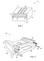
FIG. 1 is a perspective view of an example chassis housing at least a portion of a circuit card assembly, in accordance with aspects of the present specification; -
FIG. 2 is a perspective view of a portion of an electronic system having a chassis, a heat frame configured to receive a circuit card assembly and a reusable phase-change thermal interface structure, in accordance with aspects of the present specification; -
FIG. 3 is a side view of the chassis and the heat frame ofFIG. 2 , in accordance with aspects of the present specification; -
FIG. 4 is a cross-sectional view of an example electronic system employing a circuit card assembly and a reusable phase-change thermal interface structure, in accordance with aspects of the present specification; -
FIG. 5 is a perspective view of an example reusable phase-change thermal interface structure in an assembly stage, where the reusable phase-change thermal interface structure includes a metal based foam and a fusible metal based alloy, in accordance with aspects of the present specification; -
FIG. 6 is a perspective view of a portion of an example reusable phase-change thermal interface structure in an operation stage, in accordance with aspects of the present specification; and -
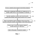
FIG. 7 is a block diagram of an example method of using the thermal interface structure, in accordance with aspects of the present specification. - Embodiments of the present specification relate to reusable phase-change thermal interface structures. In certain embodiments, a reusable phase-change thermal interface structure is configured to reduce cavities, irregularities, and crevices between mating surfaces of a heat source and a heat sink to facilitate heat transfer between the mating surfaces for at least a portion of a time period during which the system is in operation. Reducing or eliminating cavities, surface irregularities, and crevices between such mating surfaces may reduce or eliminate thermal contact resistance between the two mating surfaces and provide a path of low or least thermal resistance for heat dissipation using a conduction mechanism. In one example, the reusable phase-change thermal interface structure facilitates enhanced thermal heat transfer between a circuit card assembly and a chassis, where the circuit card assembly is disposed in the chassis in a re-insertable manner. As used herein, the term "re-insertable" suggests that the circuit card assembly may be configured to be mounted and decoupled from the chassis in a reversible manner and during normal operation of the system without the need for a system shut off.
- It should be noted that although the present specification describes the reusable phase-change thermal interface structure disposed between a circuit card assembly and a chassis, however, embodiments of the present specification are operable with any apparatus that performs the functionality illustrated and described herein, or its equivalent. For example, and without limitation, the reusable phase-change thermal interface structure described herein may be disposed between a power supply unit and a base plate, a chassis and cooling fins, a chassis and a base plate, and the like, to reduce a thermal resistance between the heat sink and the heat source.
- As used herein, an element or step recited in the singular and proceeded with the word "a" or "an" should be understood as not excluding plural of the elements or steps, unless such exclusion is explicitly stated. Furthermore, references to "one embodiment" are not intended to be interpreted as excluding the existence of additional embodiments that also incorporate the recited features. Moreover, unless explicitly stated to the contrary, embodiments "comprising" or "having" an element or a plurality of elements having a particular property may include additional such elements not having that property.
- One or more specific embodiments of the present specification will be described below. In an effort to provide a concise description of these embodiments, all features of an actual implementation may not be described in the specification. It should be appreciated that in the development of any such actual implementation, as in any engineering or design project, numerous implementation-specific decisions must be made to achieve the developers' specific goals, such as compliance with system-related and business-related constraints, which may vary from one implementation to another. Moreover, it should be appreciated that such a development effort might be complex and time consuming, but would nevertheless be a routine undertaking of design, fabrication, and manufacture for those of ordinary skill having the benefit of this specification.
-
FIG. 1 is aperspective view 10 of anexample chassis 12 configured to be operatively coupled and decoupled to acircuit card assembly 18 more than once. Thechassis 12 may include afirst wall 13, asecond wall 14, and a pair ofside walls 16. Theside walls 16 of thechassis 12 may include aslot 20 to receive thecircuit card assembly 18. In one example, theslot 20 may be configured to receive thecircuit card assembly 18 in a slidable manner. The circuit card assembly may be configured to be reversibly coupled and decoupled to thechassis 12. In one embodiment, thechassis 12 may have an open front and an open back to facilitate air flow through thechassis 12 and over thecircuit card assembly 18. In another embodiment, however, thechassis 12 may be enclosed such that air is not permitted to flow into, or out of, thechassis 12 when thecircuit card assembly 18 is mounted in theslot 20. Optionally, thechassis 12 may include a vent (not shown) configured to facilitate airflow into, and out of, thechassis 12. Alternatively or additionally, thechassis 12 may include a plurality ofexternal fins 24 to facilitate convective heat transfer from thechassis 12 to air flowing over an exterior of thechassis 12 so as to facilitate heat dissipation from thecircuit card assembly 18. -
FIGS. 2 and3 illustrate a portion of an arrangement illustrated inFIG. 1. FIG. 2 illustrates aperspective view 30 andFIG. 3 illustrates across-sectional view 32 of a portion of an electronic system (not shown) having achassis 36 and aheat frame 38 configured to receive a circuit card assembly (not shown). In the illustrated embodiment, thechassis 36 is in the form of a housing. The circuit card assembly may be disposed in thechassis 36 in a re-insertable manner such that the circuit card assembly may be operatively coupled and decoupled from the chassis 36more than once. Thechassis 36 includes afirst wall 40 and asecond wall 42 that form areceptor 44. Thereceptor 44 may extend along alength 46 of thechassis 36. Thereceptor 44 may include afirst surface 48 and asecond surface 50. Thereceptor 44 may be configured to receive at least a portion of the heat sink, such as aheat frame 38. Theheat frame 38 may be operatively coupled to the circuit card assembly. A reusable phase-changethermal interface structure 56 may be disposed in areceptacle 58 formed in theheat frame 38. Theheat frame 38 may be configured to facilitate exchange of heat between the circuit card assembly and thechassis 36 via the reusable phase-changethermal interface structure 56 to provide thermal cooling to the circuit card assembly. In particular, theheat frame 38 is configured to facilitate heat transfer from the circuit card assembly to thechassis 36. Theheat frame 38 may include a physical structure that is suitable to receive the circuit card assembly. - Advantageously, the reusable phase-change
thermal interface structure 56 is configured to provide a path of least thermal resistance to the heat or thermal energy being dissipated from the circuit card assembly to thechassis 36 via theheat frame 38. The reusable phase-changethermal interface structure 56 may be disposed between theheat frame 38 and thechassis 36. As will be described in detail with respect toFIGS. 5 and 6 , the reusable phase-changethermal interface structure 56 includes metal based foam and a fusible metal based alloy. The fusible metal based alloy is configured to change from a solid phase to a liquid phase and vice versa. By way of example, at an assembly temperature or at an assembly stage, the fusible metal based alloy may be present at least in a portion of the metal based foam, while, at an operating temperature or during an operation stage, the fusible metal based alloy may convert to the liquid phase and may exist in the liquid phase during the operation of the system due to an increase in temperature of the system. When in the liquid phase, the fusible metal based alloy may be disposed on at least a portion of an outer surface of the metal based foam and may be configured to fill in at least a portion of surface irregularities present at the interface of theheat frame 38 and thechassis 36. Further, when in the liquid phase the fusible metal based alloy may also be disposed in an internal portion of the metal-based foam. Accordingly, the metal based foam provides a support and entrainment structure to the fusible metal based alloy, resulting in prevention of possible leakage of the fusible metal based alloy when the two mating surfaces are not in contact. Moreover, the fusible metal based alloy provides an enhanced thermal conductivity path between the heat source and the heat sink. - As used herein, the term "assembly temperature" refers generally to a temperature in the electronic system at which temperature the fusible metal based alloy exists in a solid phase. Similarly, as used herein, the term "assembly stage" refers to the stage of the electronic system before or sometime after the operation of the electronic system when the electronic system is at the assembly temperature, or when the fusible metal based alloy exists in the solid phase. Further, as used herein the term "operating temperature" is the temperature at which the electronic system including the reusable phase-change
thermal interface structure 56 is performing an assigned operation. Also, as used herein, the term "operation stage" refers to the stage of the electronic system when the electronic system is performing an assigned function. In one embodiment, at the beginning of the operation stage, as the temperature of the heat source increases, the heat is transferred to one of the surfaces coupled to the heat source, and further is transferred through a surface of the reusable phase-changethermal interface structure 56 coupled to the heat sink. During this stage, the temperature of the reusable phase-changethermal interface structure 56 increases and the fusible metal based alloy melts and transitions to a liquid phase. In one embodiment, when the operation of the system is stabilized, the heat transfer from the surface coupled to the heat source and the surface coupled to the heat sink may be facilitated through the fusible metal based alloy. Moreover, in one embodiment, the assembling temperature may be less than about 85°C. Also, in another embodiment, the assembling temperature may be in a range from about 0°C to about 50°C. In yet another embodiment, the assembling temperature may be in a range from about 15°C to about 25°C. In certain embodiments, the operating temperature may be greater than the assembling temperature. In one example, the operating temperature may be greater than about 30°C. In a particular example, the operating temperature may be in a range from about 50°C to about 125°C. - The electronic system may further includes a
wedgelock structure 52 disposed between the first andsecond walls chassis 36. Thewedgelock structure 52 may be configured to facilitate securely coupling the circuit card assembly to thechassis 36. In the illustrated embodiment, thewedgelock structure 52 may be disposed adjacent to thesecond surface 50 of thereceptor 44. It should be noted that thewedgelock structure 52 may be replaced with any other suitable mechanical locking mechanism, such as, but not limited to, a nut and bolt mechanism. -
FIG. 4 illustrates an exampleelectronic system 60 employing achassis 62, aheat frame 64, a reusable phase-changethermal interface structure 66 and acircuit card assembly 68. Thesystem 60 also may also include awedgelock mechanism 79. In one embodiment, thecircuit card assembly 68 may include one or more printedcircuit boards 70 and one ormore processors 72, such as, but not limited to, a central processing unit, a graphics processing unit, or both. In operation, theprocessors 72 may generate heat and may act as one of the heat sources in theelectronic system 60. The heat generated by theprocessors 72 may travel through theheat frame 64 to thechassis 62 via the reusable phase-changethermal interface structure 66. The reusable phase-changethermal interface structure 66 may be configured to provide a path of low thermal resistance between theheat frame 64 and thechassis 62 to facilitate heat transfer from theheat frame 64 to thechassis 62. In one embodiment, the reusable phase-changethermal interface structure 66 may be configured to reduce surface irregularities between the mating surfaces of theheat frame 64 and thechassis 62. The reusable phase-changethermal interface structure 66 is configured to provide an interface between theheat frame 64 and thechassis 62. Particularly, the reusable phase-changethermal interface structure 66 is configured to provide an interface between theheat frame 64 andwalls chassis 62. The reusable phase-changethermal interface structure 66 may be disposed in areceptacle 80 formed inrails 78 of theheat frame 64. The reusable phase-changethermal interface structure 66 may be disposed in areceptacle 77 disposed between afirst surface 65, which is a surface of thereceptacle 80; and asecond surface 69, which is a surface of a portion of thechassis 62. In one embodiment, athickness 67 of the reusable phase-changethermal interface structure 66 in between the first andsecond surfaces - In one embodiment, the
second surface 69 may have a desirable smoothness configured to decrease adherence of the reusable phase-changethermal interface structure 66 to thesecond surface 69. By way of example, a roughness of thesecond surface 69 may be less than about 25 µm. In one embodiment, the roughness of thesecond surface 69 is less than about 5 µm. In one embodiment, thesecond surface 69 may include a non-wetting composition for the reusable phase-changethermal interface structure 66. As used herein the term "non-wetting composition for the reusable phase-change thermal interface structure" refers to a composition of thesecond surface 69 that does not have any chemical or physical affinity to the reusable phase-changethermal interface structure 66. Thesecond surface 69 may include aluminum, an aluminum composite, copper, or a copper composite. In one embodiment, thesecond surface 69 may be coated with oxides, nickel, chrome, or black anodized coating. In another embodiment, thesecond surface 69 is an aluminum surface. - Moreover, in one embodiment, the mating surfaces 65 and 69 of the
heat frame 64 and thewall 74 of thechassis 62, respectively, are configured such that the surfaces of theheat frame 64 having the reusable phase-changethermal interface structure 66 and thechassis 62 are amenable to be frequently separated from each other. For example, in one embodiment, the mating surfaces are separated from each other and coupled again at least about 100 times in an operating life cycle. In the referencedelectronic system 60, thecircuit card assembly 68, and theheat frame 64 along with the reusable phase-changethermal interface structure 66 may be easily removed from thechassis 62, thereby facilitating hassle-free removal of at least a portion of thecircuit card assembly 68 from thechassis 62. In one example, only one printed circuit board of thecircuit card assembly 68 may be reversibly removed from thechassis 62. -
FIG. 5 illustrates an example of a reusable phase-changethermal interface structure 81. The reusable phase-changethermal interface structure 81 includes a metal basedfoam 82 as a matrix, and a fusible metal based alloy (not shown) disposed at least in a portion of the matrix of the metal basedfoam 82. In the assembly stage or any time before or after operation of the electronic system employing the reusable phase-change thermal interface structure, the fusible metal based alloy may be disposed in at least a portion of a volume of the matrix. In one embodiment, the fusible metal based alloy may be disposed only within the portion of the metal based foam. In the assembly stage or before or after operation of the electronic system employing the reusable phase-change thermal interface structure, the fusible metal based alloy may not be disposed on an outer side of one ormore surfaces 86 of the metal basedfoam 82. Accordingly, in the assembly stage or before or after operation of the electronic system, the fusible metal based alloy may not be in contact with the heat source. - As will be appreciated, the currently available thermally conductive interfaces are not configured for re-usability. For example, removal of thermal interface materials may require cleaning of surfaces on which the thermal interface material is disposed. Moreover, as will be appreciated, cleaning the surfaces to remove thermal interface material at each dismantling may be cumbersome as well as time consuming. Further, in some cases, the thermal interface materials may not be reusable, and need to be discarded after each use and replaced by a new thermal interface material. For example, the liquid thermal interface material may not be used in re-insertable components due to difficulties in cleaning the surfaces employing such thermal interface materials. Advantageously, the reusable phase-change
thermal interface structure 81 may be easily coupled with the surrounding structures, such as, but not limited to, the heat frame, the chassis, and the like. In the operation stage, the fusible metal based alloy disposed on thesurface 86 of the metal basedfoam 82 may act as a liquid thermal interface material, and may have advantages, such as, but not limited to, a smooth interface, associated with a liquid based thermal interface material. While, before or after operation, the fusible metal based alloy may exist in the solid phase and hence, may be easily decoupled from at least a portion of the electronic system. Hence, the structure of the reusable phase-change thermal interface structure provides the advantages of a liquid thermal interface material, while avoiding the problems associated with the liquid thermal interface material. - In certain embodiments, the metal based
foam 82 may include a cellular structure having a solid metal based material, such as, but not limited to, a metal, a metal alloy, a metal composite, metallites, and pores disposed between the solid metal based material. Non-limiting examples of the solid metal based material may include aluminum, titanium, tantalum, copper, or alloys or composites thereof. As used herein, the term "foam" may entail a specifically designed, machined or three-dimensional (3D) printed structure. In some embodiments, the metal based foam may include non-metallic components, such as, but not limited to, polymers, grapheme, or like materials. In one embodiment, a volume fraction of the pores, also referred to as "porosity" may be in a range from about 40% to about 95% of the volume of the metal basedfoam 82. The porosity of the metal basedfoam 82 may be determined based on a desirable mechanical strength for given dimensions of the reusable phase-change thermal interface structure. In some embodiments, pores 88 in the metal basedfoam 82 may be interconnected to form an interconnected network of thepores 88. In certain embodiments, the metal basedfoam 82 may include porous structures or open-celled foam having an interconnected network of solid struts having a determined pore density or volume fraction of pores. The open-celled structure may be isotropic or anisotropic in a 3D space. In some other embodiments, the metal basedfoam 82 may include a combination of sealed andinterconnected pores 88. The sealed pores may be pores that are disconnected from neighboring pores. The nature of pores (sealed or interconnected) and size and density of pores of the metal basedfoam 82 may be controlled during manufacturing of the foam. The metal basedfoam 82 82 is thermally conductive, and may have a coefficient of thermal expansion that is similar to the coefficient of thermal expansion of the material from which the metal basedfoam 82 is made of. By way of example, the coefficient of thermal expansion of aluminum based foam may be similar to the coefficient of thermal expansion of aluminum metal. - The metal based
foam 82 may exhibit properties, such as, but not limited to, thermal shock resistance, high temperature resistance, corrosion resistance, resistance to wear and thermal cycling, resistance to high pressure, shock absorption, machinability, and combinations thereof. Thermal conductivity of the metal basedfoam 82 may be enhanced by disposing a fusible metal based alloy in at least a portion of the metal basedfoam 82. In one embodiment, the metal basedfoam 82 of the reusable phase-change thermal interface structure may experiences a pressure in a range from about 35 kPa (5 psi) to about 6900 kPa (1000 psi) at the operating temperature. - In the assembly stage, the fusible metal based alloy may be in a solid phase. Whereas, in the operation stage, the fusible metal based alloy may exist in a liquid phase and may be configured to be disposed on at least a portion of one or more outer surfaces of the metal based foam 84. In some embodiments, in the liquid phase, the fusible metal based alloy is configured to be pumped out of one or
more pores 88 of the metal basedfoam 82 in the liquid phase. After operation, the fusible metal based alloy is configured to retract in the metal based foam prior to reconversion from the liquid phase to the solid phase. In certain embodiments, the fusible metal based alloy may include indium, bismuth, tin, gallium, lead or alloys, or combinations thereof. Further, in some embodiments, the metal based alloy may include alloys with one or more filler materials. The fillers may be used to enhance the thermal and/or mechanical properties of the fusible metal based alloy. Non-limiting examples of the fillers may include particles, rods, fibers, or combinations thereof. Moreover, in some embodiments, the fusible metal based alloy may have a melting point in a range from about 40°C to about 220°C. The fusible metal based alloys may have a thermal conductivity in a range from about 10W/mK to about 90W/mK. Non-limiting examples of the fusible metal based alloys may include low temperature alloys, such as, but not limited to, indium, bismuth, tin, lead, gallium, or combinations thereof. - An effective thermal conductivity of the reusable phase-change thermal interface structure is a composite value based on individual thermal conductivities of the metal based
foam 82, and fusible metal based alloy. In one embodiment, the thermal conductivity of the reusable phase-change thermal interface structure may be greater than about 1W/mK. In one embodiment, the thermal conductivity of the reusable phase-change thermal interface structure may be in a range from about 5W/mK to about 200W/mK. In one embodiment, the thermal conductivity of the reusable phase-change thermal interface structure may be in a range from about 5W/mK to about 25/mK. In another embodiment, the thermal conductivity of the reusable phase-change thermal interface structure may be in a range from about 100W/mK to about 125/mK. The reusable phase-change thermal interface structure used herein is such that the material is solid at an assembling temperature and liquid at an operating temperature. As used herein the "assembling temperature" is the temperature at which the combination of the first surface and the reusable phase-changethermal interface structure 56 is brought in contact. - In certain embodiments, the reusable phase-change thermal interface structure may exhibit optimal thermal and mechanical properties and may be compatible with the present standard electronic assembly processes. Further, the reusable phase-change thermal interface structure may exhibit low bulk and interface thermal resistances, sufficient compliance to absorb thermally induced strain without causing early fatigue failure, sufficient conformability to accommodate surface roughness of the surfaces, ability to be processed at relatively low temperatures, robustness during storage and operation, and ability to be reworked and reused. Moreover, the reusable interface structure may be configured to account for manufacturing tolerances and other variables associated with fabricating a circuit card assembly. The devices, systems, and methods disclosed herein further facilitate reducing inconsistencies (such as gaps) in the contact between an electronic component of a circuit card assembly and the heat transfer device dedicated to cooling the electronic component. Additionally, the embodiments disclosed herein facilitate reducing thermal resistance in a processor of a circuit card assembly so as to mitigate the temperature increase of the processor during operation, thereby increasing processor power.
-
FIG. 6 illustrates a reusable phase-changethermal interface structure 92 in the operation stage of the electronic system employing the reusable phase-changethermal interface structure 92. In the illustrated embodiment, the reusable phase-changethermal interface structure 92 may include a metal basedfoam 94 and a fusible metal basedalloy 96. The fusible metal basedalloy 96 may be disposed as alayer 98 on one or moreouter surfaces 100 of the metal basedfoam 94. Further, a portion of the fusible metal basedalloy 96 may also be disposed in a volume of thefoam 94. Thelayer 98 of the fusible metal based alloy may be configured to provide a smoother interface between a heat source and a heat sink by filling one or more cavities and crevices that may exist at the interface of the heat frame and the chassis. Thelayer 98 of the fusible metal based alloy formed on theouter surfaces 100 of the metal basedfoam 94 may be continuous or discontinuous. - After operation of the electronic system, when the heat source (e.g., circuit card assembly) and heat sink (e.g., chassis) attains a determined temperature, and there is little or no need for heat transfer between the heat source and the heat sink, the fusible metal based
alloy 96 may be configured to retract in the metal basedfoam 94. It may be noted that "after operation" may include instances in time immediately after operation, or at a determined time after the device is switched off. The fusible metal basedalloy 96 may be configured to retract instantly or gradually. Further, the fusible metal basedalloy 96 may be configured to retract in the metal basedfoam 94 completely or partially. In one example, a very small portion of the fusible metal basedalloy 96 may remain on a surface of the metal basedfoam 94, where the surface is disposed adjacent the heat sink. Once the fusible metal basedalloy 96 is retracted in the metal basedfoam 94, the fusible metal basedalloy 96 may be configured to solidify. At this instance, the circuit card assembly may be taken out of the chassis without causing any damage, or leaving any impurity of the interface material on the rails. - In one example, the fusible metal based
alloy 96 may be configured to instantly liquefy when the temperature of the heat sink exceeds a determined temperature. Further, the fusible metal based alloy may be configured to instantly retract and solidify when the temperature of the heat sink reaches below a determined temperature. Accordingly, a composition of the fusible metal based alloy may be such that the fusible metal based alloy is configured to switch between the liquid and solid phases within a relatively short time of few nanoseconds based on the melting point of the fusible metal based alloy. -
FIG. 7 illustrates a flow diagram 110 of an example method of use of a reusable phase-change thermal interface structure employed in an electronic system. Atblock 112, one or more reusable phase-change thermal interface structures may be provided. In one embodiment, the reusable phase-change thermal interface structure may be provided at an assembly temperature. Furthermore, atblock 114, the reusable phase-change thermal interface structures may be disposed in one or more corresponding receptacles in a heat frame. In one embodiment, the reusable phase-change thermal interface structures may be coupled to the corresponding receptacle using mechanical designs (e.g., shims, shoulders, etc.) or chemical means (e.g., adhesives) that facilitate retaining the reusable phase-change thermal interface structures in their respective positions during coupling and decoupling of circuit card assembly. Atblock 116, the heat frame having the reusable phase-change thermal interface structure may be operatively coupled to a chassis. In one embodiment, the heat frame may be reversibly operatively coupled to the chassis such that the heat frame may be decoupled from the chassis when required. By way of example, after operation, the heat frame along with the circuit card assembly may be removed from the chassis. Atblock 118, an electronic system employing the heat frame having the reusable phase-change thermal interface structures may be powered on. At block 120, a thermal path of low thermal resistance may be provided between a heat source (e.g., circuit card assembly) in the electronic system and the heat frame. The step of providing the path of low thermal resistance between the heat frame and the heat source may include heating the reusable phase-change thermal interface structure to a temperature above a melting point of a fusible metal alloy. The thermal path of low thermal resistance is provided due to presence of a fusible liquid metal alloy on a surface of the metal based foam. Furthermore, atblock 122, the electronic system may be turned off. Subsequently; the fusible metal based alloy may retract in the metal based foam. Additionally, the reusable phase-change thermal interface structure may be cooled to a temperature below the melting point of the fusible metal based alloy to detach the heat frame from the chassis. - In certain embodiments, the metal based foam provides a support and entrainment structure to the fusible metal based alloy, resulting in prevention of possible leakage when the two mating surfaces are not in contact during the operation. In addition, the fusible metal based alloy provides an enhanced thermal conductivity path between the heat source and the heat sink. Hence, the reusable phase-change thermal interface structure is suitable for use in places where one or more components between which the reusable phase-change thermal interface structure is disposed need to be removed and re-inserted more than once. In one embodiment, surfaces of the chassis and the circuit card assembly having the reusable phase-change thermal interface structure are configured such that the first and second surfaces are amenable to be frequently separated from each other. For example, in one embodiment, the first and second surfaces are separated from each other and coupled again at least about 100 times in an operating life cycle. In one embodiment, different first surfaces are used along with one second surface. Also, in one embodiment, different second surfaces are used along with one first surface.
- Advantageously, the re-usable thermal interface structure of the present specification includes optimal thermal and mechanical properties and is compatible with the present standard electronic assembly processes. Non-limiting examples of such thermal and mechanical properties may include low bulk and interface thermal resistances, sufficient compliance to absorb thermally induced strain without causing early fatigue failure, sufficient conformability to accommodate surface roughness of the surfaces, ability to be processed at relatively low temperatures, robustness during storage and operation, and ability to be reworked and reused.
- While only certain features of the invention have been illustrated and described herein, many modifications and changes will occur to those skilled in the art. It is, therefore, to be understood that the appended claims are intended to cover all such modifications and changes as fall within the scope of the invention.
- Various aspects and embodiments of the present invention are defined by the following numbered clauses:
- 1. A reusable phase-change thermal interface structure, comprising:
- a metal based foam; and
- a fusible metal based alloy, wherein in a solid phase of the fusible metal based alloy the fusible metal based alloy is disposed at least in a portion of the metal based foam, and wherein in a liquid phase of the fusible metal based alloy the fusible metal based alloy is disposed at least on a portion of one or more outer surfaces of the metal based foam.
- 2. The reusable phase-change thermal interface structure of clause 1, wherein the metal based foam comprises interconnected pores.
- 3. The reusable phase-change thermal interface structure of any preceding clause, wherein the metal based foam comprises porous structures or an interconnected network of solid struts.
- 4. The reusable phase-change thermal interface structure of any preceding clause, wherein the metal based foam comprises aluminum, tantalum, titanium, copper, or alloys or composites thereof.
- 5. The reusable phase-change thermal interface structure of any preceding clause, wherein the fusible metal based alloy comprises indium, bismuth, tin, gallium, lead or alloys, or combinations thereof.
- 6. The reusable phase-change thermal interface structure of any preceding clause, wherein the fusible metal based alloy is configured to be pumped out of one or more pores of the metal based foam in the liquid phase of the fusible metal based alloy.
- 7. The reusable phase-change thermal interface structure of any preceding clause, wherein the fusible metal based alloy is configured to retract in the metal based foam prior to conversion from the liquid phase to the solid phase.
- 8. The reusable phase-change thermal interface structure of any preceding clause, wherein the fusible metal based alloy is configured to exist in the solid phase at an assembling temperature, and wherein the fusible metal based alloy is configured to exist in the liquid phase at an operating temperature.
- 9. The reusable phase-change thermal interface structure of any preceding clause, wherein the assembling temperature of the reusable phase-change thermal interface structure is less than about 85°C.
- 10. The reusable phase-change thermal interface structure of any preceding clause, wherein the operating temperature of the reusable phase-change thermal interface structure is greater than about 30°C.
- 11. The reusable phase-change thermal interface structure of any preceding clause, wherein the fusible metal based alloy is configured to exist in the liquid phase at a temperature in a range from about 40°C to about 220°C.
- 12. The reusable phase-change thermal interface structure of any preceding clause, wherein the reusable phase-change thermal interface structure has a thermal conductivity equal to or more than about 1 W/mK.
- 13. An electronic system, comprising:
- a first surface;
- a second surface; and
- a reusable phase-change thermal interface structure disposed between the first and second surfaces, wherein the reusable phase-change thermal interface structure comprises:
- a metal based foam; and
- a fusible metal based alloy, wherein in a solid phase of the fusible metal based alloy the fusible metal based alloy is disposed at least in a portion of the metal based foam, and wherein in a liquid phase of the fusible metal based alloy the fusible metal based alloy is disposed at least on a portion of one or more outer surfaces of the metal based foam,
- wherein the fusible metal based alloy is configured to be in the solid phase at an assembling temperature and in the liquid phase at an operating temperature.
- 14. The electronic system of any preceding clause, wherein a thickness of the reusable phase-change thermal interface structure disposed between the first and second surfaces during operation is in a range from about 10 microns to about 1000 microns.
- 15. The electronic system of any preceding clause, wherein the first surface has a surface roughness equal to or greater than about 25 microns.
- 16. The electronic system of any preceding clause, wherein the reusable phase-change thermal interface structure experiences a pressure in a range from about 35 kPa (5 psi) to about 6900 kPa (1000 psi) at the operating temperature.
- 17. The electronic system of any preceding clause, further comprising:
- a chassis; and
- a circuit card assembly mounted on the chassis, wherein the circuit card assembly comprises:
- a printed circuit board;
- at least one electronic component mounted on the printed circuit board; and
- a heat frame coupled to the circuit card assembly and configured to provide a thermal dissipation path for dissipating heat generated by the at least one electronic component to the chassis using the heat frame,
- wherein the reusable phase-change thermal interface structure is operatively coupled to the chassis and the heat frame, and wherein the reusable phase-change thermal interface structure is configured to facilitate heat dissipation from the at least one electronic component by transferring heat generated by the electronic component to the chassis.
- 18. The electronic system of any preceding clause, wherein the at least one electronic component is a processor.
- 19. The electronic system of any preceding clause, further comprising a wedgelock structure disposed in a receptor of the chassis.
- 20. The electronic system of any preceding clause, wherein the reusable phase-change thermal interface structure is disposed on the first surface, and wherein the first surface is a part of a receptacle in the heat frame.
- 21. A method, comprising:
- providing a reusable phase-change thermal interface structure;
- disposing the reusable phase-change thermal interface structure in at least a portion of one or more receptacles of a heat frame;
- reversibly operatively coupling the heat frame having the reusable phase-change thermal interface structure to a chassis;
- providing power to an electronic system, wherein the electronic system employs a heat source and the heat frame having the reusable phase-change thermal interface structure;
- providing a path of low thermal resistance between the heat frame and the heat source; and
- switching off the power of the electronic system.
- 22. The method of any preceding clause, wherein the step of providing the path of low thermal resistance between the heat frame and the heat source comprises heating the reusable phase-change thermal interface structure to a temperature above a melting point of a fusible metal alloy of the reusable phase-change thermal interface structure.
- 23. The method of any preceding clause, further comprising cooling the reusable phase-change thermal interface structure to a temperature below the melting point of the fusible metal based alloy to decouple the heat frame from the chassis.
Claims (15)
- A reusable phase-change thermal interface structure, comprising:a metal based foam; anda fusible metal based alloy, wherein in a solid phase of the fusible metal based alloy the fusible metal based alloy is disposed at least in a portion of the metal based foam, and wherein in a liquid phase of the fusible metal based alloy the fusible metal based alloy is disposed at least on a portion of one or more outer surfaces of the metal based foam.
- The reusable phase-change thermal interface structure of claim 1, wherein the metal based foam comprises interconnected pores.
- The reusable phase-change thermal interface structure of claim 1, wherein the metal based foam comprises porous structures or an interconnected network of solid struts.
- The reusable phase-change thermal interface structure of claim 1, 2 or 3, wherein the metal based foam comprises aluminum, tantalum, titanium, copper, or alloys or composites thereof.
- The reusable phase-change thermal interface structure of any of claims 1 to 4, wherein the fusible metal based alloy comprises indium, bismuth, tin, gallium, lead or alloys, or combinations thereof.
- The reusable phase-change thermal interface structure of any preceding claim, wherein the fusible metal based alloy is configured to be pumped out of one or more pores of the metal based foam in the liquid phase of the fusible metal based alloy.
- The reusable phase-change thermal interface structure of any preceding claim, wherein the fusible metal based alloy is configured to retract in the metal based foam prior to conversion from the liquid phase to the solid phase.
- The reusable phase-change thermal interface structure of any preceding claim, wherein the fusible metal based alloy is configured to exist in the solid phase at an assembling temperature, and wherein the fusible metal based alloy is configured to exist in the liquid phase at an operating temperature.
- The reusable phase-change thermal interface structure of claim 8, wherein the assembling temperature of the reusable phase-change thermal interface structure is less than about 85°C.
- The reusable phase-change thermal interface structure of claim 8, wherein the operating temperature of the reusable phase-change thermal interface structure is greater than about 30°C.
- The reusable phase-change thermal interface structure of claim 8, wherein the fusible metal based alloy is configured to exist in the liquid phase at a temperature in a range from about 40°C to about 220°C.
- An electronic system, comprising:a first surface;a second surface; anda reusable phase-change thermal interface structure disposed between the first and second surfaces, wherein the reusable phase-change thermal interface structure comprises:a metal based foam; anda fusible metal based alloy, wherein in a solid phase of the fusible metal based alloy the fusible metal based alloy is disposed at least in a portion of the metal based foam, and wherein in a liquid phase of the fusible metal based alloy the fusible metal based alloy is disposed at least on a portion of one or more outer surfaces of the metal based foam,wherein the fusible metal based alloy is configured to be in the solid phase at an assembling temperature and in the liquid phase at an operating temperature.
- The electronic system of claim 12, wherein a thickness of the reusable phase-change thermal interface structure disposed between the first and second surfaces during operation is in a range from about 10 microns to about 1000 microns.
- The electronic system of claim 12 or 13, wherein the first surface has a surface roughness equal to or greater than about 25 microns.
- A method, comprising:providing a reusable phase-change thermal interface structure;disposing the reusable phase-change thermal interface structure in at least a portion of one or more receptacles of a heat frame;reversibly operatively coupling the heat frame having the reusable phase-change thermal interface structure to a chassis;providing power to an electronic system, wherein the electronic system employs a heat source and the heat frame having the reusable phase-change thermal interface structure;providing a path of low thermal resistance between the heat frame and the heat source; andswitching off the power of the electronic system.
Applications Claiming Priority (1)
| Application Number | Priority Date | Filing Date | Title |
|---|---|---|---|
| US14/103,868 US9826662B2 (en) | 2013-12-12 | 2013-12-12 | Reusable phase-change thermal interface structures |
Publications (1)
| Publication Number | Publication Date |
|---|---|
| EP2883930A1 true EP2883930A1 (en) | 2015-06-17 |
Family
ID=52133838
Family Applications (1)
| Application Number | Title | Priority Date | Filing Date |
|---|---|---|---|
| EP14197291.9A Ceased EP2883930A1 (en) | 2013-12-12 | 2014-12-11 | Reusable phase-change thermal interface structures |
Country Status (2)
| Country | Link |
|---|---|
| US (1) | US9826662B2 (en) |
| EP (1) | EP2883930A1 (en) |
Cited By (6)
| Publication number | Priority date | Publication date | Assignee | Title |
|---|---|---|---|---|
| US20150168087A1 (en) * | 2013-12-12 | 2015-06-18 | General Electric Company | Reusable phase-change thermal interface structures |
| US10385469B2 (en) * | 2017-09-11 | 2019-08-20 | Toyota Motor Engineering & Manufacturing North America, Inc. | Thermal stress compensation bonding layers and power electronics assemblies incorporating the same |
| CN110505797A (en) * | 2019-09-19 | 2019-11-26 | Oppo广东移动通信有限公司 | Heat dissipation substrate, manufacturing method of heat dissipation substrate and electronic device |
| WO2022245992A1 (en) * | 2021-05-19 | 2022-11-24 | Indium Corporation | Solid metal foam thermal interface material |
| US12428587B1 (en) | 2024-09-03 | 2025-09-30 | Boston Materials, Inc. | Liquid metal compositions and methods |
| WO2026054756A1 (en) * | 2024-09-03 | 2026-03-12 | Boston Materials, Inc. | Liquid metal compositions and methods |
Families Citing this family (24)
| Publication number | Priority date | Publication date | Assignee | Title |
|---|---|---|---|---|
| JP6269094B2 (en) * | 2014-01-20 | 2018-01-31 | Tdk株式会社 | Power supply |
| US9357670B2 (en) * | 2014-02-18 | 2016-05-31 | Lockheed Martin Corporation | Efficient heat transfer from conduction-cooled circuit cards |
| GB2536603B (en) * | 2014-10-07 | 2021-02-17 | Aker Solutions Ltd | Subsea electronic device |
| US10117357B2 (en) * | 2015-07-20 | 2018-10-30 | Futurewei Technologies, Inc. | Stationary cooling structure for board/chassis-level conduction cooling |
| US10269682B2 (en) * | 2015-10-09 | 2019-04-23 | Taiwan Semiconductor Manufacturing Company, Ltd. | Cooling devices, packaged semiconductor devices, and methods of packaging semiconductor devices |
| TWI625874B (en) * | 2015-11-05 | 2018-06-01 | 華邦電子股份有限公司 | Conductive-bridging random access memory |
| FR3045226B1 (en) * | 2015-12-15 | 2017-12-22 | Schneider Electric Ind Sas | COOLING DEVICE FOR HOT GASES IN HIGH VOLTAGE EQUIPMENT |
| CN106455446B (en) * | 2016-10-28 | 2019-02-15 | 曙光信息产业(北京)有限公司 | Cooling device for heating element and method for manufacturing the same |
| US10470338B2 (en) * | 2017-01-10 | 2019-11-05 | Aselsan Elektronik Sanayi Ve Ticaret Anonim Sirketi | Cooling system |
| DE102018101453A1 (en) * | 2018-01-23 | 2019-07-25 | Borgwarner Ludwigsburg Gmbh | Heating device and method for producing a heating rod |
| US10212850B1 (en) * | 2018-04-13 | 2019-02-19 | Eagle Technology, Llc | Electronic device with heat sink flange and related methods |
| US10791652B2 (en) * | 2018-06-12 | 2020-09-29 | Eagle Technology, Llc | Systems and methods for heatsink to rail thermal interface enhancement |
| CN109894602A (en) * | 2019-03-07 | 2019-06-18 | 青岛科技大学 | A kind of high thermal conductivity composite heat interfacial material with two-phase co-continuous communicating structure |
| CN109897611A (en) * | 2019-03-18 | 2019-06-18 | 中国工程物理研究院激光聚变研究中心 | High heat capacity liquid metal for conducting heat material and preparation method thereof, phase change composite material |
| US11037860B2 (en) | 2019-06-27 | 2021-06-15 | International Business Machines Corporation | Multi layer thermal interface material |
| CN110290686A (en) * | 2019-07-24 | 2019-09-27 | 中国科学院理化技术研究所 | A composite cooling system |
| EP3905859B1 (en) * | 2020-04-01 | 2023-08-30 | Hamilton Sundstrand Corporation | Thermal management of planar transformer windings and cores |
| US11774190B2 (en) | 2020-04-14 | 2023-10-03 | International Business Machines Corporation | Pierced thermal interface constructions |
| US12213285B2 (en) * | 2021-07-23 | 2025-01-28 | Ametek, Inc. | Conduction cooled chassis |
| US11503701B1 (en) * | 2021-10-26 | 2022-11-15 | Eagle Technology, Llc | Electronic device having heat transfer clamp and associated methods |
| US11665856B2 (en) * | 2021-10-26 | 2023-05-30 | Eagle Technology, Llc | Electronic device having flexible, heat conductive layer and associated methods |
| CN114497813B (en) * | 2022-03-31 | 2022-06-28 | 深圳市森若新材科技有限公司 | Phase change composite film and battery and chip assembly including the same |
| US20230418009A1 (en) * | 2022-06-26 | 2023-12-28 | International Business Machines Corporation | Thermal management of computer hardware modules |
| US11997824B2 (en) | 2022-08-17 | 2024-05-28 | Eagle Technology, Llc | Systems and methods for providing a high performance air-cooled chassis for electronic modules |
Citations (3)
| Publication number | Priority date | Publication date | Assignee | Title |
|---|---|---|---|---|
| US5323294A (en) * | 1993-03-31 | 1994-06-21 | Unisys Corporation | Liquid metal heat conducting member and integrated circuit package incorporating same |
| US20060157223A1 (en) * | 2005-01-18 | 2006-07-20 | Gelorme Jeffrey D | Heterogeneous thermal interface for cooling |
| US20130224510A1 (en) * | 2012-02-29 | 2013-08-29 | General Electric Company | System including thermal interface material |
Family Cites Families (92)
| Publication number | Priority date | Publication date | Assignee | Title |
|---|---|---|---|---|
| SE355741B (en) | 1967-10-11 | 1973-05-07 | Siemens Ag | |
| US3852803A (en) | 1973-06-18 | 1974-12-03 | Gen Electric | Heat sink cooled power semiconductor device assembly having liquid metal interface |
| US4034469A (en) | 1976-09-03 | 1977-07-12 | Ibm Corporation | Method of making conduction-cooled circuit package |
| US4920574A (en) * | 1985-10-04 | 1990-04-24 | Fujitsu Limited | Cooling system for an electronic circuit device |
| US5126919A (en) * | 1985-10-04 | 1992-06-30 | Fujitsu Limited | Cooling system for an electronic circuit device |
| US4879632A (en) * | 1985-10-04 | 1989-11-07 | Fujitsu Limited | Cooling system for an electronic circuit device |
| US5198189A (en) | 1989-08-03 | 1993-03-30 | International Business Machines Corporation | Liquid metal matrix thermal paste |
| US5291371A (en) * | 1990-04-27 | 1994-03-01 | International Business Machines Corporation | Thermal joint |
| US5616421A (en) * | 1991-04-08 | 1997-04-01 | Aluminum Company Of America | Metal matrix composites containing electrical insulators |
| US5570502A (en) * | 1991-04-08 | 1996-11-05 | Aluminum Company Of America | Fabricating metal matrix composites containing electrical insulators |
| US6003221A (en) * | 1991-04-08 | 1999-12-21 | Aluminum Company Of America | Metal matrix composites containing electrical insulators |
| US5225964A (en) * | 1991-10-31 | 1993-07-06 | Rockwell International Corporation | Integrated lightweight card rack |
| US6728113B1 (en) * | 1993-06-24 | 2004-04-27 | Polychip, Inc. | Method and apparatus for non-conductively interconnecting integrated circuits |
| DE4446489C1 (en) | 1994-12-23 | 1996-05-15 | Fraunhofer Ges Forschung | Process for manipulating microcomponents and device for carrying out the process |
| US6632522B1 (en) * | 1995-02-16 | 2003-10-14 | 3M Innovative Properties Company | Blended pressure-sensitive adhesives |
| DE19533169C2 (en) | 1995-09-08 | 2002-02-07 | Fraunhofer Ges Forschung | solder deposit |
| US5572404A (en) * | 1995-09-21 | 1996-11-05 | Unisys Corporation | Heat transfer module incorporating liquid metal squeezed from a compliant body |
| US5561590A (en) * | 1995-09-21 | 1996-10-01 | Unisys Corporation | Heat transfer sub-assembly incorporating liquid metal surrounded by a seal ring |
| US5673176A (en) * | 1995-12-06 | 1997-09-30 | Dell Usa, L.P. | Integrated circuit dual cooling paths and method for constructing same |
| SE505163C2 (en) * | 1996-02-21 | 1997-07-07 | Ericsson Telefon Ab L M | Heat conducting device |
| US5808874A (en) * | 1996-05-02 | 1998-09-15 | Tessera, Inc. | Microelectronic connections with liquid conductive elements |
| US6286206B1 (en) * | 1997-02-25 | 2001-09-11 | Chou H. Li | Heat-resistant electronic systems and circuit boards |
| US6033506A (en) * | 1997-09-02 | 2000-03-07 | Lockheed Martin Engery Research Corporation | Process for making carbon foam |
| US6108208A (en) | 1997-12-08 | 2000-08-22 | Unisys Corporation | Testing assembly having a pressed joint with a single layer of thermal conductor which is reused to sequentially test multiple circuit modules |
| US6243944B1 (en) | 1997-12-08 | 2001-06-12 | Unisys Corporation | Residue-free method of assembling and disassembling a pressed joint with low thermal resistance |
| US6281573B1 (en) * | 1998-03-31 | 2001-08-28 | International Business Machines Corporation | Thermal enhancement approach using solder compositions in the liquid state |
| US6220607B1 (en) * | 1998-04-17 | 2001-04-24 | Applied Materials, Inc. | Thermally conductive conformal media |
| US6246582B1 (en) | 1998-12-30 | 2001-06-12 | Honeywell Inc. | Interchangeable stiffening frame with extended width wedgelock for use in a circuit card module |
| US6212075B1 (en) | 1998-12-30 | 2001-04-03 | Honeywell Inc. | Adapter kit to allow extended width wedgelock for use in a circuit card module |
| US6391442B1 (en) * | 1999-07-08 | 2002-05-21 | Saint-Gobain Performance Plastics Corporation | Phase change thermal interface material |
| US6343647B2 (en) | 2000-01-11 | 2002-02-05 | Thermax International, Ll.C. | Thermal joint and method of use |
| US6372997B1 (en) | 2000-02-25 | 2002-04-16 | Thermagon, Inc. | Multi-layer structure and method for forming a thermal interface with low contact resistance between a microelectronic component package and heat sink |
| US7369411B2 (en) * | 2000-02-25 | 2008-05-06 | Thermagon, Inc. | Thermal interface assembly and method for forming a thermal interface between a microelectronic component package and heat sink |
| US6501663B1 (en) * | 2000-02-28 | 2002-12-31 | Hewlett Packard Company | Three-dimensional interconnect system |
| TW201006846A (en) | 2000-03-07 | 2010-02-16 | Senomyx Inc | T1R taste receptor and genes encidung same |
| US6949822B2 (en) * | 2000-03-17 | 2005-09-27 | International Rectifier Corporation | Semiconductor multichip module package with improved thermal performance; reduced size and improved moisture resistance |
| US6404634B1 (en) * | 2000-12-06 | 2002-06-11 | Hewlett-Packard Company | Single piece heat sink for computer chip |
| MXPA03006498A (en) * | 2001-01-22 | 2003-10-15 | Parker Hannifin Corp | IT WILL ENTER THERMAL CHANGE OF PHASE, CLEAN RELEASE. |
| US20030112603A1 (en) | 2001-12-13 | 2003-06-19 | Roesner Arlen L. | Thermal interface |
| US7023699B2 (en) * | 2002-06-10 | 2006-04-04 | Visteon Global Technologies, Inc. | Liquid cooled metal thermal stack for high-power dies |
| US6914357B2 (en) * | 2002-06-10 | 2005-07-05 | Visteon Global Technologies, Inc. | Electric machine with integrated power electronics |
| CN1681648A (en) * | 2002-07-15 | 2005-10-12 | 霍尼韦尔国际公司 | Thermal interconnect and interface systems, methods of production and uses thereof |
| US6757170B2 (en) * | 2002-07-26 | 2004-06-29 | Intel Corporation | Heat sink and package surface design |
| US6665186B1 (en) * | 2002-10-24 | 2003-12-16 | International Business Machines Corporation | Liquid metal thermal interface for an electronic module |
| DE10250604A1 (en) * | 2002-10-30 | 2004-05-19 | Tyco Electronics Amp Gmbh | Integrated circuit system with latent heat storage module |
| EP1616337A2 (en) * | 2003-04-02 | 2006-01-18 | Honeywell International, Inc. | Thermal interconnect and interface systems, methods of production and uses thereof |
| US7744991B2 (en) * | 2003-05-30 | 2010-06-29 | 3M Innovative Properties Company | Thermally conducting foam interface materials |
| WO2005062831A2 (en) * | 2003-12-21 | 2005-07-14 | Albers Walter F | Migro-cycle energy transfer systems and methods |
| US6849941B1 (en) * | 2004-01-07 | 2005-02-01 | Thermagon, Inc. | Heat sink and heat spreader assembly |
| DE602005017472D1 (en) * | 2004-03-09 | 2009-12-17 | Henkel Corp | HEAT-CONDUCTIVE TWO-COMPONENT ADHESIVE COMPOSITION |
| US20060109631A1 (en) | 2004-11-02 | 2006-05-25 | Data Device Corporation | Method and apparatus for connecting circuit cards employing a cooling technique to achieve desired temperature thresholds and card alignment |
| US7554190B2 (en) * | 2004-12-03 | 2009-06-30 | Chris Macris | Liquid metal thermal interface material system |
| US7482197B2 (en) | 2004-12-17 | 2009-01-27 | International Business Machines Corporation | Method and apparatus for deploying a liquid metal thermal interface for chip cooling |
| US7345877B2 (en) * | 2005-01-06 | 2008-03-18 | The Boeing Company | Cooling apparatus, system, and associated method |
| TWI259051B (en) * | 2005-01-21 | 2006-07-21 | Delta Electronics Inc | Heat dispersion module |
| US7312527B2 (en) * | 2005-12-16 | 2007-12-25 | Intel Corporation | Low temperature phase change thermal interface material dam |
| US8058101B2 (en) * | 2005-12-23 | 2011-11-15 | Tessera, Inc. | Microelectronic packages and methods therefor |
| US7440281B2 (en) * | 2006-02-01 | 2008-10-21 | Apple Inc. | Thermal interface apparatus |
| US20070253169A1 (en) | 2006-05-01 | 2007-11-01 | Honeywell International Inc. | Wedgelock device for increased thermal conductivity of a printed wiring wiring assembly |
| US7397664B2 (en) * | 2006-05-22 | 2008-07-08 | Sun Microsystems, Inc. | Heatspreader for single-device and multi-device modules |
| US7349221B2 (en) * | 2006-07-20 | 2008-03-25 | Honeywell International Inc. | Device for increased thermal conductivity between a printed wiring assembly and a chassis |
| US7709296B2 (en) * | 2006-10-19 | 2010-05-04 | International Business Machines Corporation | Coupling metal clad fiber optics for enhanced heat dissipation |
| TWI325046B (en) * | 2006-12-01 | 2010-05-21 | Delta Electronics Inc | Heat dissipation module and flat heat column and heat dissipation apparatus thereof |
| US20100034335A1 (en) | 2006-12-19 | 2010-02-11 | General Electric Company | Articles having enhanced wettability |
| US20080186678A1 (en) | 2007-02-06 | 2008-08-07 | Dell Products L.P. | Nanoparticle Enhanced Heat Conduction Apparatus |
| US8448693B2 (en) * | 2007-02-08 | 2013-05-28 | Lundell Manufacturing Corporation | Sealed thermal interface component |
| US7709951B2 (en) * | 2007-03-16 | 2010-05-04 | International Business Machines Corporation | Thermal pillow |
| US7898076B2 (en) | 2007-04-30 | 2011-03-01 | International Business Machines Corporation | Structure and methods of processing for solder thermal interface materials for chip cooling |
| US20080291634A1 (en) * | 2007-05-22 | 2008-11-27 | Weiser Martin W | Thermal interconnect and interface materials, methods of production and uses thereof |
| US20090001576A1 (en) | 2007-06-29 | 2009-01-01 | Surinder Tuli | Interconnect using liquid metal |
| US7838418B2 (en) | 2007-12-11 | 2010-11-23 | Apple Inc. | Spray dispensing method for applying liquid metal |
| TW200936028A (en) | 2008-02-05 | 2009-08-16 | Thermoshuttle Co Ltd | Thermal module and system applied the phase-change metal thermal interface material |
| WO2009131913A2 (en) * | 2008-04-21 | 2009-10-29 | Honeywell International Inc. | Thermal interconnect and interface materials, methods of production and uses thereof |
| US9500416B2 (en) * | 2008-05-31 | 2016-11-22 | The Boeing Company | Thermal management device and method for making the same |
| US20090301691A1 (en) * | 2008-06-10 | 2009-12-10 | Dynalene Inc. | Active Multiphase Heat Transportation System |
| US8023269B2 (en) * | 2008-08-15 | 2011-09-20 | Siemens Energy, Inc. | Wireless telemetry electronic circuit board for high temperature environments |
| US9057568B2 (en) * | 2008-12-16 | 2015-06-16 | California Institute Of Technology | Temperature control devices and methods |
| CN101826467B (en) * | 2009-03-02 | 2012-01-25 | 清华大学 | Preparation method of thermal interface material |
| US20100294475A1 (en) * | 2009-05-22 | 2010-11-25 | General Electric Company | High performance heat transfer device, methods of manufacture thereof and articles comprising the same |
| US8405996B2 (en) * | 2009-06-30 | 2013-03-26 | General Electric Company | Article including thermal interface element and method of preparation |
| US8324719B2 (en) * | 2009-08-31 | 2012-12-04 | General Electric Company | Electronic package system |
| US8477500B2 (en) * | 2010-05-25 | 2013-07-02 | General Electric Company | Locking device and method for making the same |
| US9507391B2 (en) * | 2011-11-28 | 2016-11-29 | Lenovo Enterprise Solutions (Singapore) Pte. Ltd. | Heat sink with orientable fins |
| US8730674B2 (en) * | 2011-12-12 | 2014-05-20 | Toyota Motor Engineering & Manufacturing North America, Inc. | Magnetic fluid cooling devices and power electronics assemblies |
| US9658000B2 (en) * | 2012-02-15 | 2017-05-23 | Abaco Systems, Inc. | Flexible metallic heat connector |
| US8937810B2 (en) * | 2012-09-14 | 2015-01-20 | International Business Machines Corporation | Electronic assembly with detachable coolant manifold and coolant-cooled electronic module |
| US8947873B2 (en) * | 2012-11-26 | 2015-02-03 | International Business Machines Corporation | Immersion-cooled and conduction-cooled electronic system |
| US20150060021A1 (en) * | 2013-09-05 | 2015-03-05 | General Electric Company | Heat transfer device and an associated method of fabrication |
| US9253871B2 (en) * | 2013-10-31 | 2016-02-02 | General Electric Company | Circuit card assembly and method of fabricating the same |
| CN203707402U (en) * | 2013-12-05 | 2014-07-09 | 番禺得意精密电子工业有限公司 | Electric connector |
| US9826662B2 (en) * | 2013-12-12 | 2017-11-21 | General Electric Company | Reusable phase-change thermal interface structures |
| US9615486B2 (en) * | 2014-03-26 | 2017-04-04 | General Electric Company | Thermal interface devices |
-
2013
- 2013-12-12 US US14/103,868 patent/US9826662B2/en active Active
-
2014
- 2014-12-11 EP EP14197291.9A patent/EP2883930A1/en not_active Ceased
Patent Citations (3)
| Publication number | Priority date | Publication date | Assignee | Title |
|---|---|---|---|---|
| US5323294A (en) * | 1993-03-31 | 1994-06-21 | Unisys Corporation | Liquid metal heat conducting member and integrated circuit package incorporating same |
| US20060157223A1 (en) * | 2005-01-18 | 2006-07-20 | Gelorme Jeffrey D | Heterogeneous thermal interface for cooling |
| US20130224510A1 (en) * | 2012-02-29 | 2013-08-29 | General Electric Company | System including thermal interface material |
Non-Patent Citations (1)
| Title |
|---|
| NIHAD DUKHAN ET AL: "An improved PCM heat storage technology utilizing metal foam", THERMAL AND THERMOMECHANICAL PHENOMENA IN ELECTRONIC SYSTEMS (ITHERM), 2010 12TH IEEE INTERSOCIETY CONFERENCE ON, IEEE, PISCATAWAY, NJ, USA, 2 June 2010 (2010-06-02), pages 1 - 7, XP031743047, ISBN: 978-1-4244-5342-9 * |
Cited By (9)
| Publication number | Priority date | Publication date | Assignee | Title |
|---|---|---|---|---|
| US20150168087A1 (en) * | 2013-12-12 | 2015-06-18 | General Electric Company | Reusable phase-change thermal interface structures |
| US9826662B2 (en) * | 2013-12-12 | 2017-11-21 | General Electric Company | Reusable phase-change thermal interface structures |
| US10385469B2 (en) * | 2017-09-11 | 2019-08-20 | Toyota Motor Engineering & Manufacturing North America, Inc. | Thermal stress compensation bonding layers and power electronics assemblies incorporating the same |
| CN110505797A (en) * | 2019-09-19 | 2019-11-26 | Oppo广东移动通信有限公司 | Heat dissipation substrate, manufacturing method of heat dissipation substrate and electronic device |
| WO2022245992A1 (en) * | 2021-05-19 | 2022-11-24 | Indium Corporation | Solid metal foam thermal interface material |
| US12300567B2 (en) | 2021-05-19 | 2025-05-13 | Indium Corporation | Solid metal foam thermal interface material |
| US12451402B2 (en) | 2021-05-19 | 2025-10-21 | Indium Corporation | Liquid metal thermal interface |
| US12428587B1 (en) | 2024-09-03 | 2025-09-30 | Boston Materials, Inc. | Liquid metal compositions and methods |
| WO2026054756A1 (en) * | 2024-09-03 | 2026-03-12 | Boston Materials, Inc. | Liquid metal compositions and methods |
Also Published As
| Publication number | Publication date |
|---|---|
| US20150168087A1 (en) | 2015-06-18 |
| US9826662B2 (en) | 2017-11-21 |
Similar Documents
| Publication | Publication Date | Title |
|---|---|---|
| US9826662B2 (en) | Reusable phase-change thermal interface structures | |
| EP3174093B1 (en) | Cooled power electronic assembly | |
| US20130224510A1 (en) | System including thermal interface material | |
| CN103857264B (en) | Phase-change heat sink for transient state heat management | |
| EP3255969B1 (en) | Heat-conducting sheet and electronic device | |
| CN101760035B (en) | The using method of thermal interfacial material and this thermal interfacial material | |
| CN107936777A (en) | A kind of three-dimensional network porous thermal conductive radiating element and preparation method thereof | |
| CN102290386B (en) | Locking device and the method for the manufacture of locking device | |
| US20190246518A1 (en) | Cooling device and manufacturing method therefor | |
| US20030024120A1 (en) | Heat exchanger cast in metal matrix composite and method of making the same | |
| CN209949677U (en) | A rapid loading and unloading vacuum brazing avionics chassis | |
| CN106701031A (en) | Composite thermal interface material composed of metal mesh and low-melting-point alloy | |
| CN101971310B (en) | Method of forming a thermo pyrolytic graphite-embedded heatsink | |
| CN110021568B (en) | Thermal Radiator | |
| US8498127B2 (en) | Thermal interface material for reducing thermal resistance and method of making the same | |
| WO2020256638A1 (en) | A cold plate for liquid cooling | |
| CN112119579A (en) | power conversion device | |
| WO2013167951A1 (en) | Expansion circuit board cooling | |
| CN118363442A (en) | Heat radiation structure and heat radiation method for computer | |
| CN206686497U (en) | A kind of heat abstractor based on metal phase change thermal conductivity | |
| CN209167996U (en) | Vehicle computing unit, radiator and vehicle computing unit block | |
| CN101232792A (en) | Heat dissipation device, heat dissipation base and manufacturing method thereof | |
| CN207596775U (en) | A kind of heat conduction and heat radiation insulated compound adhesive tape with jog | |
| CN102045985A (en) | Heat dissipation module and manufacturing method thereof | |
| Åström | Thermal Performance of Solid Interface Materialsin Immersion Cooling for Data Centers |
Legal Events
| Date | Code | Title | Description |
|---|---|---|---|
| PUAI | Public reference made under article 153(3) epc to a published international application that has entered the european phase |
Free format text: ORIGINAL CODE: 0009012 |
|
| 17P | Request for examination filed |
Effective date: 20141211 |
|
| AK | Designated contracting states |
Kind code of ref document: A1 Designated state(s): AL AT BE BG CH CY CZ DE DK EE ES FI FR GB GR HR HU IE IS IT LI LT LU LV MC MK MT NL NO PL PT RO RS SE SI SK SM TR |
|
| AX | Request for extension of the european patent |
Extension state: BA ME |
|
| R17P | Request for examination filed (corrected) |
Effective date: 20151217 |
|
| RBV | Designated contracting states (corrected) |
Designated state(s): AL AT BE BG CH CY CZ DE DK EE ES FI FR GB GR HR HU IE IS IT LI LT LU LV MC MK MT NL NO PL PT RO RS SE SI SK SM TR |
|
| 17Q | First examination report despatched |
Effective date: 20160803 |
|
| 18R | Application refused |
Effective date: 20171003 |