EP2883778A1 - Truck frame for railroad vehicle - Google Patents
Truck frame for railroad vehicle Download PDFInfo
- Publication number
- EP2883778A1 EP2883778A1 EP13879543.0A EP13879543A EP2883778A1 EP 2883778 A1 EP2883778 A1 EP 2883778A1 EP 13879543 A EP13879543 A EP 13879543A EP 2883778 A1 EP2883778 A1 EP 2883778A1
- Authority
- EP
- European Patent Office
- Prior art keywords
- cross beam
- mounting bracket
- bogie frame
- mounting
- plate section
- Prior art date
- Legal status (The legal status is an assumption and is not a legal conclusion. Google has not performed a legal analysis and makes no representation as to the accuracy of the status listed.)
- Granted
Links
Images



Classifications
-
- B—PERFORMING OPERATIONS; TRANSPORTING
- B61—RAILWAYS
- B61F—RAIL VEHICLE SUSPENSIONS, e.g. UNDERFRAMES, BOGIES OR ARRANGEMENTS OF WHEEL AXLES; RAIL VEHICLES FOR USE ON TRACKS OF DIFFERENT WIDTH; PREVENTING DERAILING OF RAIL VEHICLES; WHEEL GUARDS, OBSTRUCTION REMOVERS OR THE LIKE FOR RAIL VEHICLES
- B61F5/00—Constructional details of bogies; Connections between bogies and vehicle underframes; Arrangements or devices for adjusting or allowing self-adjustment of wheel axles or bogies when rounding curves
- B61F5/50—Other details
- B61F5/52—Bogie frames
-
- B—PERFORMING OPERATIONS; TRANSPORTING
- B23—MACHINE TOOLS; METAL-WORKING NOT OTHERWISE PROVIDED FOR
- B23K—SOLDERING OR UNSOLDERING; WELDING; CLADDING OR PLATING BY SOLDERING OR WELDING; CUTTING BY APPLYING HEAT LOCALLY, e.g. FLAME CUTTING; WORKING BY LASER BEAM
- B23K2101/00—Articles made by soldering, welding or cutting
- B23K2101/24—Frameworks
Definitions
- the present invention relates to a bogie frame for railway vehicles, with particular attention to its mounting brackets for mounting functional parts such as a traction motor, a gearbox, and a brake to the bogie frame. More specifically, the present invention relates to a bogie frame for railway vehicles which is provided with enhanced welding workability for the mounting brackets to be welded to the bogie frame and also with a greater degree of design flexibility for the positions where functional parts are mounted.
- railway vehicles are composed of a vehicle body and a bogie that supports the vehicle body, and functional parts such as traction motors, gearboxes, brakes, and the like are mounted to a bogie frame of the bogie.
- Railway vehicles run on rails on power transmitted from traction motors to wheel sets through gearboxes, and braking is applied by actuating the braking system, which causes the rotation of the wheel sets to be inhibited, for example.
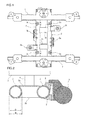
- FIG. 1 is a plan view of a conventional bogie frame.
- FIG. 2 is a cross-sectional view of cross beams of the conventional bogie frame, schematically showing an example of a configuration for mounting a functional part.
- FIG. 2 is a sectional view, taken along the direction of rails, in which a vehicle body 5 and a center pin 6 of the vehicle body are also clearly shown for ease of understanding of the configuration.
- the bogie frame includes a pair of left and right side beams 1 disposed along the direction of rails and the cross beams 2 that connect the side beams 1 to each other.
- the cross beams 2 are constituted by two round pipes having a circular cross section arranged in parallel to each other as shown in FIG. 2 , and each of them is welded at both ends thereof to the side beams 1.
- a pair of upper and lower reinforcing plates 2a and 2b is disposed between the cross beams 2 and welded to them.
- the cross beams 2 are provided with mounting brackets 3 for mounting a functional part, each welded to the outer peripheral surfaces of the cross beams 2.
- the mounting brackets 3 include a mounting bracket 3a for mounting a traction motor, a mounting bracket 3b for mounting a gearbox, and a mounting bracket 3c for mounting a brake.
- FIG. 2 illustrates a state in which the mounting bracket 3 has been welded to the outside half of the outer peripheral surface of one of the two round pipe cross beams 2, and a traction motor, as a functional part 4, has been attached to the mounting bracket 3.
- the mounting bracket 3 is formed of a plurality of steel plates welded to each other.
- a mounting bracket formed of a plurality of steel plates welded to each other has a reduced fatigue strength (according to JIS-E-4207 (Japanese Industrial Standards), for example) at the weld zone where it is welded to the cross beam and at the weld zones of the mounting bracket-forming steel plates where they are welded together, as compared to the base metal regions of the steel plates. Because of this, measures for inhibiting an unwanted decrease in fatigue strength of a mounting bracket are desired.
- Patent Literature 1 discloses a technique of modifying the shapes of the steel plates that constitute the mounting bracket to reduce stress.
- Patent Literature 2 discloses a technique of improving the quality of the weld joint by optimizing the welding procedure when fabricating the mounting bracket as well as by modifying the shapes of the steel plates that constitute the mounting bracket.
- the conventional techniques address the need by modifying the size and shape of the mounting bracket, i.e., the size and shape of the steel plates constituting the mounting bracket so as to conform to the positions where functional parts which are in conformity with specifications of railway vehicles are mounted. Needless to say, in the design modification, it is necessary to form the mounting bracket into a shape that provides sufficient strength so as to prevent a decrease in fatigue strength of the mounting bracket.
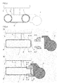
- FIG. 3 is a cross-sectional view of cross beams of the conventional bogie frame, schematically showing an example of the difficulties encountered in mounting a functional part.
- FIG. 3 shows a sectional view taken along the direction of rails as with FIG. 2 .
- FIG. 3 shows a case in which a functional part 4 is to be mounted to one of the two round pipe cross beams 2 at a location lower than the top thereof and close thereto, as required by certain specifications of railway vehicles.
- a functional part 4 there is no space for placement of a mounting bracket and thus the functional part 4 interferes with the cross beam 2.
- mounting of the functional part 4 cannot be accomplished by any modifications to the size and shape of the mounting bracket, and therefore the overall dimensional configuration of the bogie frame, including that of the cross beams 2, must be revised.
- the conventional bogie frame has a significantly low degree of design flexibility for the positions where functional parts are mounted.
- the present invention has been made in view of the foregoing problems. Accordingly, it is an object of the present invention to provide a bogie frame for railway vehicles which has enhanced welding workability for welding thereto mounting brackets for mounting a functional part and also allows a greater degree of design flexibility for the positions where functional parts are mounted.
- the present inventors intensively searched for techniques that allow mounting of functional parts to suitable positions in accordance with individual specifications of railway vehicles, while satisfying the conditions under which weld lines that are formed when mounting brackets for mounting a functional part are welded to the cross beam are relatively long and straight, and further, not necessitating a change of the overall dimensional configuration of the bogie frame including that of the cross beam.
- a bogie frame for railway vehicles comprising: a pair of left and right side beams disposed along a direction of rails; a cross beam that connects the side beams to each other; and a mounting bracket for mounting a functional part, the mounting bracket being joined to the cross beam, wherein the cross beam has a rectangular cross section and includes a top plate section, a bottom plate section, and a pair of side plate sections; the top plate section has a cutout opening extending to one of the side plate sections; the mounting bracket is inserted in the cutout opening; and the mounting bracket and the top plate section are joined together by butt welding.
- the mounting bracket is a monolithically formed component formed by forging or machining.
- the cross beam comprises a joined-four-plate body, a rectangular pipe, or a press formed product.
- the bogie frame for railway vehicles of the present invention is capable of being provided with enhanced welding workability because the weld lines, formed between the cross beam and the mounting brackets for mounting a functional part when the mounting brackets are welded to the cross beam, are relatively long and straight. Moreover, a variety of types of functional parts can be mounted to the cross beam simply by modifying the sizes and shapes of the mounting bracket and the cutout opening in accordance with individual specifications of railway vehicles. Thus, it is possible to provide a greater degree of design flexibility for the positions where functional parts are mounted.
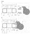
- FIG. 4 shows cross-sectional views of a cross beam of the bogie frame in accordance with a first embodiment of the present invention, which schematically shows an example of a configuration for mounting a functional part.
- FIG. 4(a) shows a state in which the functional part and the mounting bracket are detached from the cross beam
- FIG. 4(b) shows a state in which the mounting bracket has been joined to the cross beam and the functional part has been mounted thereon.
- FIG. 4 shows sectional views taken along the direction of rails as with FIG. 2 , with a traction motor being illustrated as the functional part 4.
- the bogie frame of the first embodiment shown in FIG. 4 is based on the configuration of the bogie frame shown in FIGS. 1 and 2 , and therefore redundant descriptions may not be repeated when appropriate.
- the mounting bracket 3 is composed of two vertically separate parts, an upper bracket member 31 and a lower bracket member 32, as shown in FIG. 4 .
- the upper bracket member 31 holds the functional part 4 at an upper portion thereof
- the lower bracket member 32 holds the functional part 4 at a lower portion thereof.
- Both the upper bracket member 31 and the lower bracket member 32 are monolithically formed components.
- this mounting bracket 3 (the upper bracket member 31 and the lower bracket member 32), which is a monolithically formed component, may be one formed by forging or machining.
- this mounting bracket 3 By using a forging or machining process, it is possible to form the mounting bracket 3 relatively easily even if it has a complex shape and to greatly increase the strength of the mounting bracket 3 itself (base metal region).
- the cross beam 2 has a horizontally elongated rectangular cross section and includes a top plate section 21, a bottom plate section 22, and a pair of side plate sections 23, 24.
- the cross beam 2 of the first embodiment is composed of a rectangular pipe having a horizontally elongated cross section.
- the cross beam 2 may be constructed by joining together a pair of press formed products having a channel-shaped cross section by welding, or by joining together a press formed product having a channel-shaped cross section and a steel plate by welding.
- the top plate section 21 of the cross beam 2 has an upper cutout opening 26, extending to one of the side plate sections 23 (the right-hand side plate section in FIG. 4 ), for receiving the upper bracket member 31.
- the bottom plate section 22 of the cross beam 2 has a lower cutout opening 27, similarly extending to one of the side plate sections 23, for receiving the lower bracket member 32.
- These upper cutout opening 26 and the lower cutout opening 27 are hereinafter also collectively referred to as a cutout opening 25.
- the upper bracket member 31 is inserted in the upper cutout opening 26 of the cross beam 2, and a groove is formed as appropriate in the upper bracket member 31 in conformity with the contour of the upper cutout opening 26, and then a welding process is applied. As shown in FIG. 4(b) , the upper bracket member 31 is joined to the top plate section 21 of the cross beam 2 by butt welding, and joined to the side plate section 23 (as well as a portion of the top plate section 21 closer to the side plate section 23, to be exact) by fillet welding.
- the lower bracket member 32 is inserted in the lower cutout opening 27 of the cross beam 2, and the lower bracket member 32 is subjected to welding along the contour of the lower cutout opening 27.
- the lower bracket member 32 is joined to the bottom plate section 22 of the cross beam 2 by butt welding, and joined to the side plate section 23 (as well as a portion of the bottom plate section 22 closer to the side plate section 23, to be exact) by fillet welding.
- FIG. 4(b) clearly shows a weld bead wg 1 of the butt weld and a weld bead wg 2 of the fillet weld. It is noted that the shape of the groove in the weld zone is not shown in FIG. 4(b) .
- the bogie frame fitted with the mounting bracket 3 (the upper bracket member 31 and the lower bracket member 32) which has been welded to its cross beam 2 incorporates the functional part 4 via the mounting bracket 3.
- the weld lines are relatively long and straight because of the configuration in which: a cross beam 2 with a rectangular cross section which includes a top plate section 21, a bottom plate section 22 and a pair of side plate sections 23, 24 is adopted; and then, a cutout opening 25 is formed in the top plate section 21 in such a manner that it extends to one of the side plate sections 23, the mounting bracket 3 is inserted in the cutout opening 25, and the mounting bracket 3 is joined to the top plate section 21 by butt welding.
- This configuration enhances welding workability for the mounting bracket 3 to be welded to the cross beam 2, and therefore enables automatic welding by a welding robot to be readily performed.
- fatigue strength (according to JIS-E-4207, for example) is higher at a base metal region than at a weld zone.
- the weld zone between the mounting bracket 3 and the cross beam 2 is a shape-changing portion and thus stress concentration occurs in the weld zone.
- the weld zone between the mounting bracket 3 and the cross beam 2 (the top plate section 21) is a region formed by butt welding, and therefore stress concentration does not occur in the weld zone.
- the mounting bracket 3, which is a monolithically formed component, may be formed to have a shape-changing portion in accordance with the position where the functional part 4 is mounted so that an area of stress concentration can be kept away from the weld zone.
- the monolithically formed mounting bracket 3 can have an increased sectional area along the direction of sleepers that is perpendicular to the direction of rails as compared to a mounting bracket formed of a plurality of steel plates welded to each other as employed in the conventional bogie frame, and therefore has further reduced stress concentration.
- the mounting bracket 3 of the bogie frame according to the first embodiment exhibits an increased fatigue safety factor.
- FIG. 5 shows cross-sectional views of a cross beam of the bogie frame in accordance with a second embodiment of the present invention, which schematically shows an example of a configuration for mounting a functional part.
- FIG. 5(a) shows a state in which the functional part and the mounting bracket are detached from the cross beam
- FIG. 5(b) shows a state in which the mounting bracket has been joined to the cross beam and the functional part has been mounted thereon.
- the bogie frame of the second embodiment shown in FIG. 5 is a variation of the bogie frame of the first embodiment shown in FIG. 4 , in which the configuration of the mounting bracket has been changed and accordingly the configuration of the cutout opening in the cross beam has been changed.
- the mounting bracket 3 is not composed of two vertically separate parts as shown in FIG. 5 . That is, the mounting bracket 3 of the second embodiment is composed of a single monolithically formed component that holds both upper and lower portions of the functional part 4 singly.
- the cutout opening 25 of the second embodiment is provided to receive a single mounting bracket 3 and thus is not composed of two vertically separate openings. It extends from the top plate section 21 of the cross beam 2 through one of the side plate sections 23 thereof (the right-hand side plate section in FIG. 5 ) over to the bottom plate section 22 thereof.
- the mounting bracket 3 is inserted in the cutout opening 25 of the cross beam 2, and the mounting bracket 3 is subjected to welding along the contour of the cutout opening 25. Specifically, as shown in FIG. 5(b) , the mounting bracket 3 is joined to the top plate section 21 and the bottom plate section 22 of the cross beam 2 by butt welding, and joined to the side plate section 23 by fillet welding, although at a very small area in a lower portion thereof.
- the bogie frame fitted with the mounting bracket 3 which has been welded to its cross beam 2 incorporates the functional part 4 via the mounting bracket 3.
- Such a bogie frame according to the second embodiment provides the same advantages as the bogie frame of the first embodiment as described above.
- the bogie frame of the second embodiment is particularly useful in the case in which the functional part 4 is to be mounted at a location lower than the top of the cross beam 2 and close thereto, i.e., the case in which the functional part 4 would interfere with the cross beam 2 if no measure is taken.
- FIG. 6 shows cross-sectional views of a cross beam of the bogie frame in accordance with a third embodiment of the present invention, which schematically shows an example of a configuration for mounting a functional part.
- FIG. 6(a) shows a state in which the functional part and the mounting bracket are detached from the cross beam
- FIG. 6(b) shows a state in which the mounting bracket has been joined to the cross beam and the functional part has been mounted thereon.
- the bogie frame of the third embodiment shown in FIG. 6 is a variation of the bogie frame of the first embodiment shown in FIG. 4 , in which the configuration of the cross beam has been changed.
- the cross beam 2 is composed of two rectangular pipes each having a square cross section that are arranged in parallel to each other as shown in FIG. 6 . Between the rectangular pipe cross beams 2 is disposed a pair of upper and lower reinforcing plates 2a and 2b which are welded thereto, similarly to the case of the round pipe cross beams 2 shown in FIGS. 1 and 2 .
- the cutout opening 25 of the third embodiment is composed of an upper cutout opening 26 for receiving the upper bracket member 31 and a lower cutout opening 27 for receiving the lower bracket member 32.
- the upper cutout opening 26 extends from the top plate section 21 of one of the two rectangular pipe cross beams 2 to one of the side plate sections 23 thereof (the right-hand side plate section in FIG. 6 ) which connects to the top plate section 21.
- the lower cutout opening 27 extends from the bottom plate section 22 of the rectangular pipe cross beam 2 where the upper cutout opening 26 is formed to one of the side plate sections 23 thereof (the right-hand side plate section in FIG. 6 ) which leads to the bottom plate section 22.
- the upper bracket member 31 and the lower bracket member 32 are inserted in the upper cutout opening 26 and the lower cutout opening 27, respectively, and a welding process is applied. Then, a functional part 4 is attached to the mounting bracket 3 (the upper bracket member 31 and the lower bracket member 32).
- Such a bogie frame according to the third embodiment provides the same advantages as the bogie frame of the first embodiment as described above.
- the bogie frame of the third embodiment provides the advantage of reduced stress, which is achieved by an increased second moment of area of the cross beam, as compared to the conventional bogie frame. The reasons for this are set out below.
- the second moments of area of them are compared.
- the conventional cross beam since it is a round pipe having a circular cross section, its outside diameter is d 2 and its inside diameter is d 1 ; and, in the case of the cross beam of the third embodiment, since it is a rectangular pipe having a square cross section, its outside width is d 2 and its inside width is d 1 (see FIG. 2 and FIG. 6(b) ).
- the second moment of area I A of the conventional cross beam is determined by the following equation (1)
- the second moment of area I B of the cross beam of the third embodiment is determined by the following equation (2):
- cross beam configuration of the bogie frame in the third embodiment may be applied to the bogie frame of the second embodiment as described above.
- FIG. 7 shows cross-sectional views of a cross beam of the bogie frame in accordance with a fourth embodiment of the present invention, which schematically shows an example of a configuration for mounting a functional part.
- FIG. 7(a) shows a state in which the functional part and the mounting bracket are detached from the cross beam
- FIG. 7(b) shows a state in which the mounting bracket has been joined to the cross beam and the functional part has been mounted thereon.
- the bogie frame of the fourth embodiment shown in FIG. 7 is a variation of the bogie frame of the first embodiment shown in FIG. 4 , in which the configuration of the cross beam has been changed.
- the cross beam 2 is composed of four plates joined together in such a manner that it has a horizontally elongated rectangular cross section as shown in FIG. 7 .
- the cross beam 2 of the fourth embodiment is formed of steel plates joined together by welding, which constitute the respective sections, i.e., a top plate section 21, a bottom plate section 22, and a pair of side plate sections 23, 24.
- the cross beam 2 includes therein reinforcing ribs 2c disposed parallel to the side plate sections 23, 24 to ensure sufficient strength.
- the cross beam 2 of this embodiment has an upper cutout opening 26 and a lower cutout opening 27.
- the upper bracket member 31 and the lower bracket member 32 are inserted in the upper cutout opening 26 and the lower cutout opening 27, respectively, and a welding process is applied. Then, a functional part 4 is attached to the mounting bracket 3 (the upper bracket member 31 and the lower bracket member 32).
- Such a bogie frame according to the fourth embodiment provides the same advantages as the bogie frame of the first embodiment as described above.
- cross beam configuration in the bogie frame of the fourth embodiment may also be applied to the bogie frame of the second embodiment as described above.
- FIG. 8 shows cross-sectional views of a cross beam of the bogie frame in accordance with a fifth embodiment of the present invention, which schematically shows an example of a configuration for mounting a functional part.
- FIG. 8(a) shows a state in which the functional part and the mounting bracket are detached from the cross beam
- FIG. 8(b) shows a state in which the mounting bracket has been joined to the cross beam and the functional part has been mounted thereon.
- the bogie frame of the fifth embodiment shown in FIG. 8 is a variation of the bogie frame of the first embodiment shown in FIG. 4 , in which the configuration of the mounting bracket has been changed and accordingly the configuration of the cutout opening in the cross beam has been changed.
- the mounting bracket 3 is composed of two vertically separate parts, an upper bracket member 31and a lower bracket member 32, as shown in FIG. 8 .
- the lower bracket member 32 is to be located above the lowermost portion of the cross beam 2.
- the top plate section 21 of the cross beam 2 has an upper cutout opening 26, extending to one of the side plate sections 23 (the right-hand side plate section in FIG. 8 ), for receiving the upper bracket member 31, as with the first embodiment.
- the side plate section 23 of the cross beam 2 has a lower cutout opening 27 for receiving the lower bracket member 32.
- the bottom plate section 22 of the cross beam 2 has an opening 28 for work in the vicinity of the lower cutout opening 27.
- the upper bracket member 31 is inserted in the upper cutout opening 26 of the cross beam 2, and a welding process is applied.
- the lower bracket member 32 is inserted in the lower cutout opening 27 of the cross beam 2, and a welding process is applied.
- the lower bracket member 32 is joined to the side plate section 23 of the cross beam 2 by fillet welding as shown in FIG. 8(b) .
- the bogie frame fitted with the mounting bracket 3 (the upper bracket member 31 and the lower bracket member 32) which has been welded to its cross beam 2 incorporates the functional part 4 via the mounting bracket 3.
- the functional part 4 is fixed to the lower bracket member 32 by a bolt 29, for example.
- the work of fixing may be performed through the opening 28 formed in the bottom plate section 22 of the cross beam 2.
- Such a bogie frame according to the fifth embodiment provides the same advantages as the bogie frame of the first embodiment as described above.
- mounting bracket configuration and the cross beam configuration of the bogie frame in the fifth embodiment may be applied to the bogie frames of the third and fourth embodiments as described above.
- the bogie frame for railway vehicles of the present invention is useful in a variety of railway vehicle applications.
Landscapes
- Engineering & Computer Science (AREA)
- Mechanical Engineering (AREA)
- Body Structure For Vehicles (AREA)
- Butt Welding And Welding Of Specific Article (AREA)
- Connection Of Plates (AREA)
- Mounting Of Bearings Or Others (AREA)
Abstract
Description
- The present invention relates to a bogie frame for railway vehicles, with particular attention to its mounting brackets for mounting functional parts such as a traction motor, a gearbox, and a brake to the bogie frame. More specifically, the present invention relates to a bogie frame for railway vehicles which is provided with enhanced welding workability for the mounting brackets to be welded to the bogie frame and also with a greater degree of design flexibility for the positions where functional parts are mounted.
- In general, railway vehicles are composed of a vehicle body and a bogie that supports the vehicle body, and functional parts such as traction motors, gearboxes, brakes, and the like are mounted to a bogie frame of the bogie. Railway vehicles run on rails on power transmitted from traction motors to wheel sets through gearboxes, and braking is applied by actuating the braking system, which causes the rotation of the wheel sets to be inhibited, for example.
-
FIG. 1 is a plan view of a conventional bogie frame.FIG. 2 is a cross-sectional view of cross beams of the conventional bogie frame, schematically showing an example of a configuration for mounting a functional part.FIG. 2 is a sectional view, taken along the direction of rails, in which avehicle body 5 and acenter pin 6 of the vehicle body are also clearly shown for ease of understanding of the configuration. - As shown in
FIG. 1 , the bogie frame includes a pair of left and right side beams 1 disposed along the direction of rails and thecross beams 2 that connect the side beams 1 to each other. Thecross beams 2 are constituted by two round pipes having a circular cross section arranged in parallel to each other as shown inFIG. 2 , and each of them is welded at both ends thereof to the side beams 1. To ensure integral stiffness of the two roundpipe cross beams 2, a pair of upper andlower reinforcing plates cross beams 2 and welded to them. - The
cross beams 2 are provided withmounting brackets 3 for mounting a functional part, each welded to the outer peripheral surfaces of thecross beams 2. Themounting brackets 3 include amounting bracket 3a for mounting a traction motor, a mountingbracket 3b for mounting a gearbox, and amounting bracket 3c for mounting a brake.FIG. 2 illustrates a state in which themounting bracket 3 has been welded to the outside half of the outer peripheral surface of one of the two roundpipe cross beams 2, and a traction motor, as afunctional part 4, has been attached to themounting bracket 3. Themounting bracket 3 is formed of a plurality of steel plates welded to each other. - It is to be noted that functional parts such as a traction motor, a gearbox, and a brake impose a heavy load on the bogie frame (cross beams), and therefore it is essential that mounting brackets for mounting a functional part be firm and solid with high fatigue strength. However, a mounting bracket formed of a plurality of steel plates welded to each other has a reduced fatigue strength (according to JIS-E-4207 (Japanese Industrial Standards), for example) at the weld zone where it is welded to the cross beam and at the weld zones of the mounting bracket-forming steel plates where they are welded together, as compared to the base metal regions of the steel plates. Because of this, measures for inhibiting an unwanted decrease in fatigue strength of a mounting bracket are desired.
- As a conventional technique that addresses this need, Patent Literature 1 discloses a technique of modifying the shapes of the steel plates that constitute the mounting bracket to reduce stress. Furthermore,
Patent Literature 2 discloses a technique of improving the quality of the weld joint by optimizing the welding procedure when fabricating the mounting bracket as well as by modifying the shapes of the steel plates that constitute the mounting bracket. - However, in bogie frames of the conventional type as shown in
FIGS. 1 and 2 , including the ones disclosed inPatent Literatures 1 and 2, there are many short weld lines and curved weld lines. This is because themounting bracket 3 is formed of a plurality of steel plates welded to each other, and further, themounting bracket 3 is welded to the outer peripheral surface of thecross beams 2 which are constituted by round pipes. Consequently, this is likely to reduce the efficiency of the work of welding and increase the difficulty in automatic welding by a welding robot. - Furthermore, as a matter of fact, different types of functional parts having different weights and performance (acting forces, loads, and the like) are used in accordance with individual specifications of railway vehicles. Hence, the positions at which functional parts are to be mounted in the bogie frame (cross beam) cannot be uniformly determined, and thus separate design is necessary for each railway vehicle specifications. In this regard, the conventional techniques address the need by modifying the size and shape of the mounting bracket, i.e., the size and shape of the steel plates constituting the mounting bracket so as to conform to the positions where functional parts which are in conformity with specifications of railway vehicles are mounted. Needless to say, in the design modification, it is necessary to form the mounting bracket into a shape that provides sufficient strength so as to prevent a decrease in fatigue strength of the mounting bracket.
- However, with conventional bogie frames, difficulties may arise in mounting a functional part. The difficulties are described in the following.
-
FIG. 3 is a cross-sectional view of cross beams of the conventional bogie frame, schematically showing an example of the difficulties encountered in mounting a functional part.FIG. 3 shows a sectional view taken along the direction of rails as withFIG. 2 . -
FIG. 3 shows a case in which afunctional part 4 is to be mounted to one of the two roundpipe cross beams 2 at a location lower than the top thereof and close thereto, as required by certain specifications of railway vehicles. In this case, there is no space for placement of a mounting bracket and thus thefunctional part 4 interferes with thecross beam 2. In this case, mounting of thefunctional part 4 cannot be accomplished by any modifications to the size and shape of the mounting bracket, and therefore the overall dimensional configuration of the bogie frame, including that of thecross beams 2, must be revised. Thus, the conventional bogie frame has a significantly low degree of design flexibility for the positions where functional parts are mounted. -
- Patent Literature 1: Japanese Patent No.
4292980 - Patent Literature 2: Japanese Patent No.
3873659 - The present invention has been made in view of the foregoing problems. Accordingly, it is an object of the present invention to provide a bogie frame for railway vehicles which has enhanced welding workability for welding thereto mounting brackets for mounting a functional part and also allows a greater degree of design flexibility for the positions where functional parts are mounted.
- In order to achieve the above object, the present inventors intensively searched for techniques that allow mounting of functional parts to suitable positions in accordance with individual specifications of railway vehicles, while satisfying the conditions under which weld lines that are formed when mounting brackets for mounting a functional part are welded to the cross beam are relatively long and straight, and further, not necessitating a change of the overall dimensional configuration of the bogie frame including that of the cross beam. Consequently, they have found that it is advantageous to: adopt a cross beam configuration with a rectangular cross section which includes a top plate section, a bottom plate section and a pair of side plate sections; and then form a cutout opening in the top plate section in such a manner that it extends to one of the side plate sections, insert a mounting bracket in the cutout opening, and join the mounting bracket to the top plate section by butt welding.
- The present invention has been accomplished based on this finding, and the summaries thereof are set forth below as to a bogie frame for railway vehicles. Specifically, there is provided a bogie frame for railway vehicles, comprising: a pair of left and right side beams disposed along a direction of rails; a cross beam that connects the side beams to each other; and a mounting bracket for mounting a functional part, the mounting bracket being joined to the cross beam, wherein the cross beam has a rectangular cross section and includes a top plate section, a bottom plate section, and a pair of side plate sections; the top plate section has a cutout opening extending to one of the side plate sections; the mounting bracket is inserted in the cutout opening; and the mounting bracket and the top plate section are joined together by butt welding.
- In the above-mentioned bogie frame, it is preferred that the mounting bracket is a monolithically formed component formed by forging or machining.
- Furthermore, in the above-mentioned bogie frame, it is preferred that the cross beam comprises a joined-four-plate body, a rectangular pipe, or a press formed product.
- The bogie frame for railway vehicles of the present invention is capable of being provided with enhanced welding workability because the weld lines, formed between the cross beam and the mounting brackets for mounting a functional part when the mounting brackets are welded to the cross beam, are relatively long and straight. Moreover, a variety of types of functional parts can be mounted to the cross beam simply by modifying the sizes and shapes of the mounting bracket and the cutout opening in accordance with individual specifications of railway vehicles. Thus, it is possible to provide a greater degree of design flexibility for the positions where functional parts are mounted.
-
- [
FIG. 1] FIG. 1 is a plan view of a conventional bogie frame. - [
FIG. 2] FIG. 2 is a cross-sectional view of cross beams of the conventional bogie frame, schematically showing an example of a configuration for mounting a functional part. - [
FIG. 3] FIG. 3 is a cross-sectional view of the cross beams of the conventional bogie frame, schematically showing an example of the difficulties encountered in mounting a functional part. - [
FIG. 4] FIG. 4 shows cross-sectional views of a cross beam of the bogie frame in accordance with a first embodiment of the present invention, which schematically shows an example of a configuration for mounting a functional part.FIG. 4(a) shows a state in which the functional part and the mounting bracket are detached from the cross beam, andFIG. 4(b) shows a state in which the mounting bracket has been joined to the cross beam and the functional part has been mounted thereon. - [
FIG. 5] FIG. 5 shows cross-sectional views of a cross beam of the bogie frame in accordance with a second embodiment of the present invention, which schematically shows an example of a configuration for mounting a functional part.FIG. 5(a) shows a state in which the functional part and the mounting bracket are detached from the cross beam, andFIG. 5(b) shows a state in which the mounting bracket has been joined to the cross beam and the functional part has been mounted thereon. - [
FIG. 6] FIG. 6 shows cross-sectional views of a cross beam of the bogie frame in accordance with a third embodiment of the present invention, which schematically shows an example of a configuration for mounting a functional part.FIG. 6(a) shows a state in which the functional part and the mounting bracket are detached from the cross beam, andFIG. 6(b) shows a state in which the mounting bracket has been joined to the cross beam and the functional part has been mounted thereon. - [
FIG. 7] FIG. 7 shows cross-sectional views of a cross beam of the bogie frame in accordance with a fourth embodiment of the present invention, which schematically shows an example of a configuration for mounting a functional part.FIG. 7(a) shows a state in which the functional part and the mounting bracket are detached from the cross beam, andFIG. 7(b) shows a state in which the mounting bracket has been joined to the cross beam and the functional part has been mounted thereon. - [
FIG. 8] FIG. 8 shows cross-sectional views of a cross beam of the bogie frame in accordance with a fifth embodiment of the present invention, which schematically shows an example of a configuration for mounting a functional part.FIG. 8(a) shows a state in which the functional part and the mounting bracket are detached from the cross beam, andFIG. 8(b) shows a state in which the mounting bracket has been joined to the cross beam and the functional part has been mounted thereon. - Hereinafter, embodiments of the bogie frame for railway vehicles of the present invention are described in detail.
-
FIG. 4 shows cross-sectional views of a cross beam of the bogie frame in accordance with a first embodiment of the present invention, which schematically shows an example of a configuration for mounting a functional part.FIG. 4(a) shows a state in which the functional part and the mounting bracket are detached from the cross beam, andFIG. 4(b) shows a state in which the mounting bracket has been joined to the cross beam and the functional part has been mounted thereon.FIG. 4 shows sectional views taken along the direction of rails as withFIG. 2 , with a traction motor being illustrated as thefunctional part 4. The same applies to the later-described second to fifth embodiments. The bogie frame of the first embodiment shown inFIG. 4 is based on the configuration of the bogie frame shown inFIGS. 1 and 2 , and therefore redundant descriptions may not be repeated when appropriate. - In the first embodiment, the mounting
bracket 3 is composed of two vertically separate parts, anupper bracket member 31 and alower bracket member 32, as shown inFIG. 4 . Theupper bracket member 31 holds thefunctional part 4 at an upper portion thereof, and thelower bracket member 32 holds thefunctional part 4 at a lower portion thereof. Both theupper bracket member 31 and thelower bracket member 32 are monolithically formed components. - Preferably, this mounting bracket 3 (the
upper bracket member 31 and the lower bracket member 32), which is a monolithically formed component, may be one formed by forging or machining. By using a forging or machining process, it is possible to form the mountingbracket 3 relatively easily even if it has a complex shape and to greatly increase the strength of the mountingbracket 3 itself (base metal region). - The
cross beam 2 has a horizontally elongated rectangular cross section and includes atop plate section 21, abottom plate section 22, and a pair ofside plate sections cross beam 2 of the first embodiment is composed of a rectangular pipe having a horizontally elongated cross section. Alternatively, thecross beam 2 may be constructed by joining together a pair of press formed products having a channel-shaped cross section by welding, or by joining together a press formed product having a channel-shaped cross section and a steel plate by welding. - As shown in
FIG. 4(a) , thetop plate section 21 of thecross beam 2 has anupper cutout opening 26, extending to one of the side plate sections 23 (the right-hand side plate section inFIG. 4 ), for receiving theupper bracket member 31. Thebottom plate section 22 of thecross beam 2 has alower cutout opening 27, similarly extending to one of theside plate sections 23, for receiving thelower bracket member 32. Theseupper cutout opening 26 and thelower cutout opening 27 are hereinafter also collectively referred to as acutout opening 25. - The
upper bracket member 31 is inserted in the upper cutout opening 26 of thecross beam 2, and a groove is formed as appropriate in theupper bracket member 31 in conformity with the contour of theupper cutout opening 26, and then a welding process is applied. As shown inFIG. 4(b) , theupper bracket member 31 is joined to thetop plate section 21 of thecross beam 2 by butt welding, and joined to the side plate section 23 (as well as a portion of thetop plate section 21 closer to theside plate section 23, to be exact) by fillet welding. - Likewise, the
lower bracket member 32 is inserted in thelower cutout opening 27 of thecross beam 2, and thelower bracket member 32 is subjected to welding along the contour of thelower cutout opening 27. As shown inFIG. 4(b) , thelower bracket member 32 is joined to thebottom plate section 22 of thecross beam 2 by butt welding, and joined to the side plate section 23 (as well as a portion of thebottom plate section 22 closer to theside plate section 23, to be exact) by fillet welding.FIG. 4(b) clearly shows a weld bead wg 1 of the butt weld and aweld bead wg 2 of the fillet weld. It is noted that the shape of the groove in the weld zone is not shown inFIG. 4(b) . - The bogie frame fitted with the mounting bracket 3 (the
upper bracket member 31 and the lower bracket member 32) which has been welded to itscross beam 2 incorporates thefunctional part 4 via the mountingbracket 3. - In such a bogie frame of the first embodiment, the weld lines are relatively long and straight because of the configuration in which: a
cross beam 2 with a rectangular cross section which includes atop plate section 21, abottom plate section 22 and a pair ofside plate sections cutout opening 25 is formed in thetop plate section 21 in such a manner that it extends to one of theside plate sections 23, the mountingbracket 3 is inserted in thecutout opening 25, and the mountingbracket 3 is joined to thetop plate section 21 by butt welding. This configuration enhances welding workability for the mountingbracket 3 to be welded to thecross beam 2, and therefore enables automatic welding by a welding robot to be readily performed. Moreover, a variety of types offunctional parts 4 can be mounted to thecross beam 2 simply by modifying the sizes and shapes of the mountingbracket 3 and thecutout opening 25 in accordance with individual specifications of railway vehicles. As a result, it is possible to provide a greater degree of design flexibility for the position where thefunctional part 4 is mounted. - Furthermore, it is also possible to increase the fatigue safety factor for the mounting
bracket 3. The reasons for this are set out below. Based on general technical knowledge, fatigue strength (according to JIS-E-4207, for example) is higher at a base metal region than at a weld zone. In the conventional bogie frame, the weld zone between the mountingbracket 3 and thecross beam 2 is a shape-changing portion and thus stress concentration occurs in the weld zone. In contrast, in the bogie frame of the first embodiment, the weld zone between the mountingbracket 3 and the cross beam 2 (the top plate section 21) is a region formed by butt welding, and therefore stress concentration does not occur in the weld zone. Also, the mountingbracket 3, which is a monolithically formed component, may be formed to have a shape-changing portion in accordance with the position where thefunctional part 4 is mounted so that an area of stress concentration can be kept away from the weld zone. Moreover, the monolithically formed mountingbracket 3 can have an increased sectional area along the direction of sleepers that is perpendicular to the direction of rails as compared to a mounting bracket formed of a plurality of steel plates welded to each other as employed in the conventional bogie frame, and therefore has further reduced stress concentration. For the above reasons, the mountingbracket 3 of the bogie frame according to the first embodiment exhibits an increased fatigue safety factor. -
FIG. 5 shows cross-sectional views of a cross beam of the bogie frame in accordance with a second embodiment of the present invention, which schematically shows an example of a configuration for mounting a functional part.FIG. 5(a) shows a state in which the functional part and the mounting bracket are detached from the cross beam, andFIG. 5(b) shows a state in which the mounting bracket has been joined to the cross beam and the functional part has been mounted thereon. The bogie frame of the second embodiment shown inFIG. 5 is a variation of the bogie frame of the first embodiment shown inFIG. 4 , in which the configuration of the mounting bracket has been changed and accordingly the configuration of the cutout opening in the cross beam has been changed. - In the second embodiment, the mounting
bracket 3 is not composed of two vertically separate parts as shown inFIG. 5 . That is, the mountingbracket 3 of the second embodiment is composed of a single monolithically formed component that holds both upper and lower portions of thefunctional part 4 singly. - The
cutout opening 25 of the second embodiment, as shown inFIG. 5 (a) , is provided to receive asingle mounting bracket 3 and thus is not composed of two vertically separate openings. It extends from thetop plate section 21 of thecross beam 2 through one of theside plate sections 23 thereof (the right-hand side plate section inFIG. 5 ) over to thebottom plate section 22 thereof. - The mounting
bracket 3 is inserted in thecutout opening 25 of thecross beam 2, and the mountingbracket 3 is subjected to welding along the contour of thecutout opening 25. Specifically, as shown inFIG. 5(b) , the mountingbracket 3 is joined to thetop plate section 21 and thebottom plate section 22 of thecross beam 2 by butt welding, and joined to theside plate section 23 by fillet welding, although at a very small area in a lower portion thereof. The bogie frame fitted with the mountingbracket 3 which has been welded to itscross beam 2 incorporates thefunctional part 4 via the mountingbracket 3. - Such a bogie frame according to the second embodiment provides the same advantages as the bogie frame of the first embodiment as described above. The bogie frame of the second embodiment is particularly useful in the case in which the
functional part 4 is to be mounted at a location lower than the top of thecross beam 2 and close thereto, i.e., the case in which thefunctional part 4 would interfere with thecross beam 2 if no measure is taken. -
FIG. 6 shows cross-sectional views of a cross beam of the bogie frame in accordance with a third embodiment of the present invention, which schematically shows an example of a configuration for mounting a functional part.FIG. 6(a) shows a state in which the functional part and the mounting bracket are detached from the cross beam, andFIG. 6(b) shows a state in which the mounting bracket has been joined to the cross beam and the functional part has been mounted thereon. The bogie frame of the third embodiment shown inFIG. 6 is a variation of the bogie frame of the first embodiment shown inFIG. 4 , in which the configuration of the cross beam has been changed. - In the third embodiment, the
cross beam 2 is composed of two rectangular pipes each having a square cross section that are arranged in parallel to each other as shown inFIG. 6 . Between the rectangular pipe cross beams 2 is disposed a pair of upper and lower reinforcingplates pipe cross beams 2 shown inFIGS. 1 and 2 . - The
cutout opening 25 of the third embodiment, as shown inFIG. 6(a) , is composed of an upper cutout opening 26 for receiving theupper bracket member 31 and alower cutout opening 27 for receiving thelower bracket member 32. Theupper cutout opening 26 extends from thetop plate section 21 of one of the two rectangularpipe cross beams 2 to one of theside plate sections 23 thereof (the right-hand side plate section inFIG. 6 ) which connects to thetop plate section 21. Thelower cutout opening 27 extends from thebottom plate section 22 of the rectangularpipe cross beam 2 where theupper cutout opening 26 is formed to one of theside plate sections 23 thereof (the right-hand side plate section inFIG. 6 ) which leads to thebottom plate section 22. - As with the first embodiment, the
upper bracket member 31 and thelower bracket member 32 are inserted in theupper cutout opening 26 and thelower cutout opening 27, respectively, and a welding process is applied. Then, afunctional part 4 is attached to the mounting bracket 3 (theupper bracket member 31 and the lower bracket member 32). - Such a bogie frame according to the third embodiment provides the same advantages as the bogie frame of the first embodiment as described above.
- In particular, the bogie frame of the third embodiment provides the advantage of reduced stress, which is achieved by an increased second moment of area of the cross beam, as compared to the conventional bogie frame. The reasons for this are set out below.
- Assuming that the cross beam of the bogie frame of the third embodiment and the cross beam of the conventional bogie frame have the same external dimensions, the second moments of area of them are compared. Specifically, in the case of the conventional cross beam, since it is a round pipe having a circular cross section, its outside diameter is d2 and its inside diameter is d1; and, in the case of the cross beam of the third embodiment, since it is a rectangular pipe having a square cross section, its outside width is d2 and its inside width is d1 (see
FIG. 2 andFIG. 6(b) ). - In this instance, in accordance with the formulae, the second moment of area IA of the conventional cross beam is determined by the following equation (1), and the second moment of area IB of the cross beam of the third embodiment is determined by the following equation (2):


- Also, in accordance with the formula, the bending stress σ is determined by the following equation (3) based on the second moment of area I and the bending moment M.

where h is a height. - From the above equation (3), it is seen that, when the same bending moment is produced, the bending stress σ becomes smaller as the second moment of area I increases. When IA of the cross beam of the conventional bogie frame and IB of the cross beam of the third embodiment are compared based on the above equations (1) and (2), it is noted that the factor for the third embodiment is greater than that for the conventional art. Accordingly, in the bogie frame of the third embodiment, the bending stress acting on the cross beam is reduced as compared to the case of the conventional bogie frame. Thus, the advantage of reduced stress is achieved.
- It is to be noted that the cross beam configuration of the bogie frame in the third embodiment may be applied to the bogie frame of the second embodiment as described above.
-
FIG. 7 shows cross-sectional views of a cross beam of the bogie frame in accordance with a fourth embodiment of the present invention, which schematically shows an example of a configuration for mounting a functional part.FIG. 7(a) shows a state in which the functional part and the mounting bracket are detached from the cross beam, andFIG. 7(b) shows a state in which the mounting bracket has been joined to the cross beam and the functional part has been mounted thereon. The bogie frame of the fourth embodiment shown inFIG. 7 is a variation of the bogie frame of the first embodiment shown inFIG. 4 , in which the configuration of the cross beam has been changed. - In the fourth embodiment, the
cross beam 2 is composed of four plates joined together in such a manner that it has a horizontally elongated rectangular cross section as shown inFIG. 7 . Specifically, thecross beam 2 of the fourth embodiment is formed of steel plates joined together by welding, which constitute the respective sections, i.e., atop plate section 21, abottom plate section 22, and a pair ofside plate sections cross beam 2 includes therein reinforcingribs 2c disposed parallel to theside plate sections cross beam 2 of this embodiment has anupper cutout opening 26 and alower cutout opening 27. - As with the first embodiment, the
upper bracket member 31 and thelower bracket member 32 are inserted in theupper cutout opening 26 and thelower cutout opening 27, respectively, and a welding process is applied. Then, afunctional part 4 is attached to the mounting bracket 3 (theupper bracket member 31 and the lower bracket member 32). - Such a bogie frame according to the fourth embodiment provides the same advantages as the bogie frame of the first embodiment as described above.
- It is to be noted that the cross beam configuration in the bogie frame of the fourth embodiment may also be applied to the bogie frame of the second embodiment as described above.
-
FIG. 8 shows cross-sectional views of a cross beam of the bogie frame in accordance with a fifth embodiment of the present invention, which schematically shows an example of a configuration for mounting a functional part.FIG. 8(a) shows a state in which the functional part and the mounting bracket are detached from the cross beam, andFIG. 8(b) shows a state in which the mounting bracket has been joined to the cross beam and the functional part has been mounted thereon. The bogie frame of the fifth embodiment shown inFIG. 8 is a variation of the bogie frame of the first embodiment shown inFIG. 4 , in which the configuration of the mounting bracket has been changed and accordingly the configuration of the cutout opening in the cross beam has been changed. - In the fifth embodiment, the mounting
bracket 3 is composed of two vertically separate parts, an upper bracket member 31and alower bracket member 32, as shown inFIG. 8 . Thelower bracket member 32 is to be located above the lowermost portion of thecross beam 2. - As shown in
FIG. 8(a) , thetop plate section 21 of thecross beam 2 has anupper cutout opening 26, extending to one of the side plate sections 23 (the right-hand side plate section inFIG. 8 ), for receiving theupper bracket member 31, as with the first embodiment. Theside plate section 23 of thecross beam 2 has alower cutout opening 27 for receiving thelower bracket member 32. In addition, thebottom plate section 22 of thecross beam 2 has anopening 28 for work in the vicinity of thelower cutout opening 27. - As with the first embodiment, the
upper bracket member 31 is inserted in the upper cutout opening 26 of thecross beam 2, and a welding process is applied. Also, thelower bracket member 32 is inserted in thelower cutout opening 27 of thecross beam 2, and a welding process is applied. In this process, thelower bracket member 32 is joined to theside plate section 23 of thecross beam 2 by fillet welding as shown inFIG. 8(b) . The bogie frame fitted with the mounting bracket 3 (theupper bracket member 31 and the lower bracket member 32) which has been welded to itscross beam 2 incorporates thefunctional part 4 via the mountingbracket 3. Thefunctional part 4 is fixed to thelower bracket member 32 by abolt 29, for example. The work of fixing may be performed through theopening 28 formed in thebottom plate section 22 of thecross beam 2. - Such a bogie frame according to the fifth embodiment provides the same advantages as the bogie frame of the first embodiment as described above.
- It is to be noted that the mounting bracket configuration and the cross beam configuration of the bogie frame in the fifth embodiment may be applied to the bogie frames of the third and fourth embodiments as described above.
- The bogie frame for railway vehicles of the present invention is useful in a variety of railway vehicle applications.
-
- 1: side beam, 2: cross beam, 2a, 2b: reinforcing plate,
- 2c: reinforcing rib,
- 3, 3a, 3b, 3c: mounting bracket, 4: functional part,
- 5: vehicle body, 6: center pin,
- 21: top plate section, 22: bottom plate section, 23, 24: side plate section,
- 25: cutout opening, 26: upper cutout opening, 27: lower cutout opening,
- 28: opening, 29: bolt,
- 31: upper bracket member, 32: lower bracket member,
- wg 1: weld bead of butt weld,
- wg 2: weld bead of fillet weld
Claims (3)
- A bogie frame for railway vehicles, comprising:a pair of left and right side beams disposed along a direction of rails;a cross beam that connects the side beams to each other; anda mounting bracket for mounting a functional part, the mounting bracket being joined to the cross beam,characterized in that: the cross beam has a rectangular cross section and includes a top plate section, a bottom plate section, and a pair of side plate sections; the top plate section has a cutout opening extending to one of the side plate sections; the mounting bracket is inserted in the cutout opening; and the mounting bracket and the top plate section are joined together by butt welding.
- The bogie frame for railway vehicles according to claim 1, characterized in that the mounting bracket is a monolithically formed component formed by forging or machining.
- The bogie frame for railway vehicles according to claim 1 or 2, characterized in that the cross beam comprises a joined-four-plate body, a rectangular pipe, or a press formed product.
Applications Claiming Priority (2)
| Application Number | Priority Date | Filing Date | Title |
|---|---|---|---|
| JP2012179373A JP5772761B2 (en) | 2012-08-13 | 2012-08-13 | Bogie frame for railway vehicles |
| PCT/JP2013/004357 WO2014027440A1 (en) | 2012-08-13 | 2013-07-17 | Truck frame for railroad vehicle |
Publications (3)
| Publication Number | Publication Date |
|---|---|
| EP2883778A1 true EP2883778A1 (en) | 2015-06-17 |
| EP2883778A4 EP2883778A4 (en) | 2016-05-04 |
| EP2883778B1 EP2883778B1 (en) | 2019-10-23 |
Family
ID=50285664
Family Applications (1)
| Application Number | Title | Priority Date | Filing Date |
|---|---|---|---|
| EP13879543.0A Active EP2883778B1 (en) | 2012-08-13 | 2013-07-17 | Bogie frame for railway vehicles |
Country Status (9)
| Country | Link |
|---|---|
| US (1) | US9446775B2 (en) |
| EP (1) | EP2883778B1 (en) |
| JP (1) | JP5772761B2 (en) |
| KR (1) | KR101707342B1 (en) |
| CN (1) | CN104507781B (en) |
| CA (1) | CA2879515C (en) |
| ES (1) | ES2762233T3 (en) |
| TW (1) | TWI507313B (en) |
| WO (1) | WO2014027440A1 (en) |
Cited By (1)
| Publication number | Priority date | Publication date | Assignee | Title |
|---|---|---|---|---|
| EP3375708A1 (en) * | 2017-03-17 | 2018-09-19 | Safran Landing Systems UK Limited | Aircraft landing gear assembly |
Families Citing this family (12)
| Publication number | Priority date | Publication date | Assignee | Title |
|---|---|---|---|---|
| JP5765292B2 (en) * | 2012-05-21 | 2015-08-19 | 新日鐵住金株式会社 | Bogie frame for railway vehicles |
| JP5772761B2 (en) * | 2012-08-13 | 2015-09-02 | 新日鐵住金株式会社 | Bogie frame for railway vehicles |
| JP6564300B2 (en) * | 2015-10-26 | 2019-08-21 | 日本車輌製造株式会社 | Bogie frame for railway vehicles |
| JP6864504B2 (en) * | 2017-03-07 | 2021-04-28 | 川崎重工業株式会社 | Bogie frame for railroad vehicles and railroad vehicles equipped with it |
| CN108099937A (en) * | 2018-02-01 | 2018-06-01 | 株洲时代电子技术有限公司 | A kind of Subway track engineering vehicle electrical transmission turning framework frame |
| JP6622842B2 (en) * | 2018-04-16 | 2019-12-18 | 川崎重工業株式会社 | Railcar drive cart |
| CN108909757A (en) * | 2018-06-15 | 2018-11-30 | 中车青岛四方机车车辆股份有限公司 | A kind of bogies for railway vehicles framework and bogie |
| CN113442966B (en) * | 2020-03-27 | 2022-10-18 | 比亚迪股份有限公司 | Bogie for railway vehicle and railway vehicle with same |
| CN111994117B (en) * | 2020-08-14 | 2022-05-17 | 中车唐山机车车辆有限公司 | Bogie side beam, bogie and railway vehicle |
| CN111994116A (en) * | 2020-08-14 | 2020-11-27 | 中车唐山机车车辆有限公司 | Bogie and rail vehicle |
| US12409549B2 (en) * | 2022-01-21 | 2025-09-09 | International Business Machines Corporation | Increasing strength of a robotic structure using swarm robot(s) |
| CN121693445A (en) | 2023-08-10 | 2026-03-17 | 日本制铁株式会社 | Support seat |
Family Cites Families (56)
| Publication number | Priority date | Publication date | Assignee | Title |
|---|---|---|---|---|
| US2098459A (en) * | 1935-06-11 | 1937-11-09 | John S Mcwhirter | Car truck |
| US3948188A (en) * | 1970-06-05 | 1976-04-06 | Swiss Aluminium Ltd. | Resilient railway bogie |
| US4173933A (en) * | 1974-05-08 | 1979-11-13 | Maschinenfabrik Augsburg-Nurnberg Aktiengesellschaft | High speed bogie |
| US4175772A (en) * | 1977-04-01 | 1979-11-27 | Cambria Spring Company | Vehicle suspension system having auxiliary spring for lightly loaded conditions |
| GB1580620A (en) * | 1978-05-26 | 1980-12-03 | British Railways Boards | Railway vehicles and bogies |
| US4242966A (en) * | 1979-04-26 | 1981-01-06 | Acf Industries, Incorporated | Railway car truck transom including a tubular bearing assembly |
| US4363277A (en) * | 1980-05-13 | 1982-12-14 | Dofasco Inc. | Stabilizing high speed railway truck safety device |
| EP0072328B1 (en) * | 1981-08-07 | 1985-05-08 | SOCIETE M T E Société anonyme | Bogie with orientatable wheel axles |
| US4648326A (en) * | 1985-02-22 | 1987-03-10 | Lukens General Industries, Inc. | Radial axle railway truck with axle couplings at sides transversely interconnected with each other |
| JPS63159173A (en) * | 1986-12-23 | 1988-07-02 | 三菱電機株式会社 | Truck for loading motor |
| JPS63269770A (en) * | 1987-04-27 | 1988-11-08 | Hitachi Ltd | Support device for traction motors for railway vehicles |
| DE3800587C1 (en) * | 1988-01-12 | 1989-04-27 | Krupp Brueninghaus Gmbh, 5980 Werdohl, De | |
| FR2636110B1 (en) * | 1988-09-02 | 1990-11-02 | Renault Vehicules Ind | DEVICE FOR FIXING A BLADE SPRING IN COMPOSITE MATERIAL |
| JPH04292980A (en) | 1991-03-20 | 1992-10-16 | Fujitsu Ltd | Ribbon cassette |
| JPH04113274U (en) * | 1991-03-25 | 1992-10-02 | 住友金属工業株式会社 | Railway vehicle bogie frame |
| IT1259517B (en) * | 1992-04-03 | 1996-03-20 | Fiat Ferroviaria Spa | TROLLEY FOR HIGH PERFORMANCE RAILWAY VEHICLES |
| US5632208A (en) * | 1995-11-13 | 1997-05-27 | National Castings Incorporated | Multi-axle railroad car truck |
| JP4060901B2 (en) * | 1996-10-24 | 2008-03-12 | 株式会社都市文化研究所 | Shaft box support device for bogie truck |
| DE19731867C1 (en) * | 1997-07-24 | 1998-10-29 | Abb Daimler Benz Transp | Bogie for railway vehicle |
| FR2782687B1 (en) * | 1998-09-02 | 2003-01-10 | Alstom Technology | COMPOSITE LONGERON BOGIE |
| JP2002187549A (en) * | 2000-12-22 | 2002-07-02 | Kawasaki Heavy Ind Ltd | Lightweight additive welded mounting structure for railway vehicles |
| JP3747783B2 (en) | 2001-01-16 | 2006-02-22 | 東海ゴム工業株式会社 | Anti-vibration rubber bush assembly for rail shaft connection |
| JP3873659B2 (en) | 2001-05-23 | 2007-01-24 | 住友金属工業株式会社 | Railway vehicle bogie frame, assembling method thereof, and railcar bogie |
| JP2004148948A (en) * | 2002-10-30 | 2004-05-27 | Kawasaki Heavy Ind Ltd | Trucks for railway vehicles |
| FR2862935B1 (en) * | 2003-12-02 | 2006-03-03 | Alstom | FLEXIBLE CONNECTION DEVICE BETWEEN A LONGERON AND AN AXLE BOX |
| RU2280575C2 (en) * | 2003-12-10 | 2006-07-27 | Закрытое акционерное общество "Управляющая компания ВКМ" | Vehicle bogie |
| JP4292980B2 (en) | 2003-12-18 | 2009-07-08 | 住友金属工業株式会社 | Railcar bogie frame and railcar bogie |
| PL1727720T3 (en) * | 2004-03-26 | 2008-06-30 | Skf Ab | Railway bogie |
| US8047139B2 (en) * | 2004-03-26 | 2011-11-01 | Contitech Luftfedersysteme Gmbh | Railway bogie |
| JP4731900B2 (en) * | 2004-12-16 | 2011-07-27 | 株式会社日立製作所 | Bogie frame for railway vehicles |
| JP4458013B2 (en) * | 2005-09-30 | 2010-04-28 | 株式会社Ihi | Work positioning method and apparatus |
| FR2914610A1 (en) * | 2007-04-05 | 2008-10-10 | Alstom Transport Sa | PRIMARY SUSPENSION DEVICE OF A RAIL VEHICLE BOGIE |
| CN201116124Y (en) * | 2007-11-02 | 2008-09-17 | 长春轨道客车股份有限公司 | Power steering truck frame work for low floor light railway |
| CN101565051A (en) * | 2008-04-25 | 2009-10-28 | 南车青岛四方机车车辆股份有限公司 | Central cross beam connecting type hinging framework |
| JP5227683B2 (en) * | 2008-07-22 | 2013-07-03 | 日本車輌製造株式会社 | Railcar bogie |
| ES2479591T3 (en) * | 2009-07-16 | 2014-07-24 | Siemens Ag Österreich | Translation mechanism frame for rail vehicles |
| CN201472409U (en) * | 2009-09-08 | 2010-05-19 | 南车南京浦镇车辆有限公司 | Motor transitional hanger base |
| GB2475325A (en) * | 2009-11-16 | 2011-05-18 | Bombardier Transp Gmbh | Torsion bar assembly and method, particularly for rail vehicle anti-roll bar |
| CN101700775B (en) * | 2009-11-27 | 2011-06-08 | 齐齐哈尔轨道交通装备有限责任公司 | Bogie for freight car and freight car |
| IN2012DN05112A (en) * | 2010-02-15 | 2015-10-09 | Nippon Sharyo Ltd | |
| DE102010020981A1 (en) * | 2010-05-12 | 2011-11-17 | Bombardier Transportation Gmbh | Drive for rail vehicles |
| JP5650464B2 (en) * | 2010-08-26 | 2015-01-07 | 東日本旅客鉄道株式会社 | Method for manufacturing railcar bogie |
| CN102069816A (en) * | 2010-12-27 | 2011-05-25 | 中国北车集团大连机车车辆有限公司 | Motor hanger and urban rail vehicle bogie |
| DE202011004025U1 (en) * | 2011-03-16 | 2012-07-10 | Bombardier Transportation Gmbh | Chassis frame for a chassis of a rail vehicle |
| JP5947590B2 (en) * | 2011-07-14 | 2016-07-06 | 川崎重工業株式会社 | Railcar bogie |
| CN202213591U (en) * | 2011-08-10 | 2012-05-09 | 南车青岛四方机车车辆股份有限公司 | Lightweight bogie welding framework |
| DE102011110090A1 (en) * | 2011-08-12 | 2013-02-14 | Bombardier Transportation Gmbh | Radträgeranlenkung for a rail vehicle |
| CN202243514U (en) * | 2011-08-13 | 2012-05-30 | 南车青岛四方机车车辆股份有限公司 | Highs-speed motor train unit bogie |
| JP5576990B2 (en) * | 2011-09-15 | 2014-08-20 | 株式会社ジーエイチクラフト | Leaf spring for railcar bogie |
| CN202294848U (en) * | 2011-09-27 | 2012-07-04 | 宝鸡南车时代工程机械有限公司 | A railway track car bogie frame |
| JP5878791B2 (en) * | 2012-02-29 | 2016-03-08 | 川崎重工業株式会社 | Leaf spring unit and bogie for railway vehicles using the same |
| US9352757B2 (en) * | 2012-04-06 | 2016-05-31 | Kawasaki Jukogyo Kabushiki Kaisha | Railcar bogie |
| EP2860081B1 (en) * | 2012-04-06 | 2018-05-02 | Kawasaki Jukogyo Kabushiki Kaisha | Railcar bogie |
| JP5765292B2 (en) * | 2012-05-21 | 2015-08-19 | 新日鐵住金株式会社 | Bogie frame for railway vehicles |
| JP5772761B2 (en) * | 2012-08-13 | 2015-09-02 | 新日鐵住金株式会社 | Bogie frame for railway vehicles |
| JP6038578B2 (en) * | 2012-10-03 | 2016-12-07 | 川崎重工業株式会社 | Railcar bogie with a shaft spring |
-
2012
- 2012-08-13 JP JP2012179373A patent/JP5772761B2/en active Active
-
2013
- 2013-07-17 CA CA2879515A patent/CA2879515C/en not_active Expired - Fee Related
- 2013-07-17 WO PCT/JP2013/004357 patent/WO2014027440A1/en not_active Ceased
- 2013-07-17 ES ES13879543T patent/ES2762233T3/en active Active
- 2013-07-17 KR KR1020157001891A patent/KR101707342B1/en not_active Expired - Fee Related
- 2013-07-17 CN CN201380040445.6A patent/CN104507781B/en active Active
- 2013-07-17 EP EP13879543.0A patent/EP2883778B1/en active Active
- 2013-07-17 US US14/418,092 patent/US9446775B2/en not_active Expired - Fee Related
- 2013-07-31 TW TW102127412A patent/TWI507313B/en not_active IP Right Cessation
Cited By (1)
| Publication number | Priority date | Publication date | Assignee | Title |
|---|---|---|---|---|
| EP3375708A1 (en) * | 2017-03-17 | 2018-09-19 | Safran Landing Systems UK Limited | Aircraft landing gear assembly |
Also Published As
| Publication number | Publication date |
|---|---|
| JP2014037186A (en) | 2014-02-27 |
| CA2879515C (en) | 2016-07-05 |
| TWI507313B (en) | 2015-11-11 |
| ES2762233T3 (en) | 2020-05-22 |
| KR20150023872A (en) | 2015-03-05 |
| CN104507781B (en) | 2016-09-14 |
| KR101707342B1 (en) | 2017-02-15 |
| CA2879515A1 (en) | 2014-02-20 |
| EP2883778B1 (en) | 2019-10-23 |
| US20150203132A1 (en) | 2015-07-23 |
| CN104507781A (en) | 2015-04-08 |
| WO2014027440A1 (en) | 2014-02-20 |
| EP2883778A4 (en) | 2016-05-04 |
| TW201420403A (en) | 2014-06-01 |
| US9446775B2 (en) | 2016-09-20 |
| JP5772761B2 (en) | 2015-09-02 |
Similar Documents
| Publication | Publication Date | Title |
|---|---|---|
| EP2883778B1 (en) | Bogie frame for railway vehicles | |
| EP2853464B1 (en) | Bogie frame for railway vehicle | |
| RU2480364C2 (en) | Railway vehicle frame | |
| KR20110074723A (en) | Structural I-beam Car Suspension Arm | |
| US10766509B2 (en) | Longitudinal support and transverse support for a chassis frame of a rail vehicle | |
| CN103538631A (en) | Hydroformed side pillar to lower back joint structure | |
| WO2013157464A1 (en) | Rail vehicle body structure | |
| EP1171339B1 (en) | Vehicle frame and method of manufacture thereof | |
| RU2677751C2 (en) | Construction of front sill, floor and headboard of cargo box on pickup truck | |
| US9868329B2 (en) | Spring bracket arm | |
| US7021721B2 (en) | Axle housing with suspension flange | |
| RU190782U1 (en) | Rail vehicle frame | |
| KR20100115385A (en) | Bumper beam for a vehicle | |
| RU2678797C1 (en) | Trailer frame and trailer trolley with such frame | |
| AU2015101794A4 (en) | Chassis Assembly | |
| EP3339130B1 (en) | Bogie for railway vehicle | |
| US20210206198A1 (en) | Wheel for a commercial vehicle, and use thereof | |
| CN107472283B (en) | Trailer framework and trailer bogie with same | |
| CN208608265U (en) | The installation frame mechanism of new energy battery pack | |
| RU2656929C2 (en) | Suspension member and method of its manufacture | |
| EP4234341A1 (en) | Closed crossmember construction comprising two elongated profiles | |
| CN206030996U (en) | Condenser installation component and vehicle with same | |
| RU2187439C1 (en) | Vehicle roof | |
| CN102267492A (en) | Automobile longitudinal beam structure |
Legal Events
| Date | Code | Title | Description |
|---|---|---|---|
| PUAI | Public reference made under article 153(3) epc to a published international application that has entered the european phase |
Free format text: ORIGINAL CODE: 0009012 |
|
| 17P | Request for examination filed |
Effective date: 20150310 |
|
| AK | Designated contracting states |
Kind code of ref document: A1 Designated state(s): AL AT BE BG CH CY CZ DE DK EE ES FI FR GB GR HR HU IE IS IT LI LT LU LV MC MK MT NL NO PL PT RO RS SE SI SK SM TR |
|
| AX | Request for extension of the european patent |
Extension state: BA ME |
|
| DAX | Request for extension of the european patent (deleted) | ||
| RA4 | Supplementary search report drawn up and despatched (corrected) |
Effective date: 20160404 |
|
| RIC1 | Information provided on ipc code assigned before grant |
Ipc: B61F 5/52 20060101AFI20160329BHEP |
|
| GRAP | Despatch of communication of intention to grant a patent |
Free format text: ORIGINAL CODE: EPIDOSNIGR1 |
|
| STAA | Information on the status of an ep patent application or granted ep patent |
Free format text: STATUS: GRANT OF PATENT IS INTENDED |
|
| RAP1 | Party data changed (applicant data changed or rights of an application transferred) |
Owner name: NIPPON STEEL CORPORATION |
|
| INTG | Intention to grant announced |
Effective date: 20190606 |
|
| GRAS | Grant fee paid |
Free format text: ORIGINAL CODE: EPIDOSNIGR3 |
|
| GRAA | (expected) grant |
Free format text: ORIGINAL CODE: 0009210 |
|
| STAA | Information on the status of an ep patent application or granted ep patent |
Free format text: STATUS: THE PATENT HAS BEEN GRANTED |
|
| AK | Designated contracting states |
Kind code of ref document: B1 Designated state(s): AL AT BE BG CH CY CZ DE DK EE ES FI FR GB GR HR HU IE IS IT LI LT LU LV MC MK MT NL NO PL PT RO RS SE SI SK SM TR |
|
| REG | Reference to a national code |
Ref country code: GB Ref legal event code: FG4D |
|
| REG | Reference to a national code |
Ref country code: CH Ref legal event code: EP |
|
| REG | Reference to a national code |
Ref country code: IE Ref legal event code: FG4D |
|
| REG | Reference to a national code |
Ref country code: DE Ref legal event code: R096 Ref document number: 602013062135 Country of ref document: DE |
|
| REG | Reference to a national code |
Ref country code: AT Ref legal event code: REF Ref document number: 1193314 Country of ref document: AT Kind code of ref document: T Effective date: 20191115 |
|
| REG | Reference to a national code |
Ref country code: CH Ref legal event code: NV Representative=s name: E. BLUM AND CO. AG PATENT- UND MARKENANWAELTE , CH |
|
| REG | Reference to a national code |
Ref country code: NL Ref legal event code: MP Effective date: 20191023 |
|
| REG | Reference to a national code |
Ref country code: LT Ref legal event code: MG4D |
|
| PG25 | Lapsed in a contracting state [announced via postgrant information from national office to epo] |
Ref country code: FI Free format text: LAPSE BECAUSE OF FAILURE TO SUBMIT A TRANSLATION OF THE DESCRIPTION OR TO PAY THE FEE WITHIN THE PRESCRIBED TIME-LIMIT Effective date: 20191023 Ref country code: BG Free format text: LAPSE BECAUSE OF FAILURE TO SUBMIT A TRANSLATION OF THE DESCRIPTION OR TO PAY THE FEE WITHIN THE PRESCRIBED TIME-LIMIT Effective date: 20200123 Ref country code: PT Free format text: LAPSE BECAUSE OF FAILURE TO SUBMIT A TRANSLATION OF THE DESCRIPTION OR TO PAY THE FEE WITHIN THE PRESCRIBED TIME-LIMIT Effective date: 20200224 Ref country code: PL Free format text: LAPSE BECAUSE OF FAILURE TO SUBMIT A TRANSLATION OF THE DESCRIPTION OR TO PAY THE FEE WITHIN THE PRESCRIBED TIME-LIMIT Effective date: 20191023 Ref country code: LT Free format text: LAPSE BECAUSE OF FAILURE TO SUBMIT A TRANSLATION OF THE DESCRIPTION OR TO PAY THE FEE WITHIN THE PRESCRIBED TIME-LIMIT Effective date: 20191023 Ref country code: NL Free format text: LAPSE BECAUSE OF FAILURE TO SUBMIT A TRANSLATION OF THE DESCRIPTION OR TO PAY THE FEE WITHIN THE PRESCRIBED TIME-LIMIT Effective date: 20191023 Ref country code: NO Free format text: LAPSE BECAUSE OF FAILURE TO SUBMIT A TRANSLATION OF THE DESCRIPTION OR TO PAY THE FEE WITHIN THE PRESCRIBED TIME-LIMIT Effective date: 20200123 Ref country code: SE Free format text: LAPSE BECAUSE OF FAILURE TO SUBMIT A TRANSLATION OF THE DESCRIPTION OR TO PAY THE FEE WITHIN THE PRESCRIBED TIME-LIMIT Effective date: 20191023 Ref country code: LV Free format text: LAPSE BECAUSE OF FAILURE TO SUBMIT A TRANSLATION OF THE DESCRIPTION OR TO PAY THE FEE WITHIN THE PRESCRIBED TIME-LIMIT Effective date: 20191023 Ref country code: GR Free format text: LAPSE BECAUSE OF FAILURE TO SUBMIT A TRANSLATION OF THE DESCRIPTION OR TO PAY THE FEE WITHIN THE PRESCRIBED TIME-LIMIT Effective date: 20200124 |
|
| REG | Reference to a national code |
Ref country code: ES Ref legal event code: FG2A Ref document number: 2762233 Country of ref document: ES Kind code of ref document: T3 Effective date: 20200522 |
|
| PG25 | Lapsed in a contracting state [announced via postgrant information from national office to epo] |
Ref country code: HR Free format text: LAPSE BECAUSE OF FAILURE TO SUBMIT A TRANSLATION OF THE DESCRIPTION OR TO PAY THE FEE WITHIN THE PRESCRIBED TIME-LIMIT Effective date: 20191023 Ref country code: IS Free format text: LAPSE BECAUSE OF FAILURE TO SUBMIT A TRANSLATION OF THE DESCRIPTION OR TO PAY THE FEE WITHIN THE PRESCRIBED TIME-LIMIT Effective date: 20200224 Ref country code: RS Free format text: LAPSE BECAUSE OF FAILURE TO SUBMIT A TRANSLATION OF THE DESCRIPTION OR TO PAY THE FEE WITHIN THE PRESCRIBED TIME-LIMIT Effective date: 20191023 |
|
| PG25 | Lapsed in a contracting state [announced via postgrant information from national office to epo] |
Ref country code: AL Free format text: LAPSE BECAUSE OF FAILURE TO SUBMIT A TRANSLATION OF THE DESCRIPTION OR TO PAY THE FEE WITHIN THE PRESCRIBED TIME-LIMIT Effective date: 20191023 |
|
| REG | Reference to a national code |
Ref country code: DE Ref legal event code: R097 Ref document number: 602013062135 Country of ref document: DE |
|
| PG2D | Information on lapse in contracting state deleted |
Ref country code: IS |
|
| PG25 | Lapsed in a contracting state [announced via postgrant information from national office to epo] |
Ref country code: EE Free format text: LAPSE BECAUSE OF FAILURE TO SUBMIT A TRANSLATION OF THE DESCRIPTION OR TO PAY THE FEE WITHIN THE PRESCRIBED TIME-LIMIT Effective date: 20191023 Ref country code: RO Free format text: LAPSE BECAUSE OF FAILURE TO SUBMIT A TRANSLATION OF THE DESCRIPTION OR TO PAY THE FEE WITHIN THE PRESCRIBED TIME-LIMIT Effective date: 20191023 Ref country code: CZ Free format text: LAPSE BECAUSE OF FAILURE TO SUBMIT A TRANSLATION OF THE DESCRIPTION OR TO PAY THE FEE WITHIN THE PRESCRIBED TIME-LIMIT Effective date: 20191023 Ref country code: DK Free format text: LAPSE BECAUSE OF FAILURE TO SUBMIT A TRANSLATION OF THE DESCRIPTION OR TO PAY THE FEE WITHIN THE PRESCRIBED TIME-LIMIT Effective date: 20191023 Ref country code: IS Free format text: LAPSE BECAUSE OF FAILURE TO SUBMIT A TRANSLATION OF THE DESCRIPTION OR TO PAY THE FEE WITHIN THE PRESCRIBED TIME-LIMIT Effective date: 20200223 |
|
| PLBE | No opposition filed within time limit |
Free format text: ORIGINAL CODE: 0009261 |
|
| STAA | Information on the status of an ep patent application or granted ep patent |
Free format text: STATUS: NO OPPOSITION FILED WITHIN TIME LIMIT |
|
| PG25 | Lapsed in a contracting state [announced via postgrant information from national office to epo] |
Ref country code: SM Free format text: LAPSE BECAUSE OF FAILURE TO SUBMIT A TRANSLATION OF THE DESCRIPTION OR TO PAY THE FEE WITHIN THE PRESCRIBED TIME-LIMIT Effective date: 20191023 Ref country code: SK Free format text: LAPSE BECAUSE OF FAILURE TO SUBMIT A TRANSLATION OF THE DESCRIPTION OR TO PAY THE FEE WITHIN THE PRESCRIBED TIME-LIMIT Effective date: 20191023 |
|
| 26N | No opposition filed |
Effective date: 20200724 |
|
| REG | Reference to a national code |
Ref country code: AT Ref legal event code: UEP Ref document number: 1193314 Country of ref document: AT Kind code of ref document: T Effective date: 20191023 |
|
| PG25 | Lapsed in a contracting state [announced via postgrant information from national office to epo] |
Ref country code: SI Free format text: LAPSE BECAUSE OF FAILURE TO SUBMIT A TRANSLATION OF THE DESCRIPTION OR TO PAY THE FEE WITHIN THE PRESCRIBED TIME-LIMIT Effective date: 20191023 |
|
| PG25 | Lapsed in a contracting state [announced via postgrant information from national office to epo] |
Ref country code: MC Free format text: LAPSE BECAUSE OF FAILURE TO SUBMIT A TRANSLATION OF THE DESCRIPTION OR TO PAY THE FEE WITHIN THE PRESCRIBED TIME-LIMIT Effective date: 20191023 |
|
| REG | Reference to a national code |
Ref country code: BE Ref legal event code: MM Effective date: 20200731 |
|
| PG25 | Lapsed in a contracting state [announced via postgrant information from national office to epo] |
Ref country code: LU Free format text: LAPSE BECAUSE OF NON-PAYMENT OF DUE FEES Effective date: 20200717 |
|
| PG25 | Lapsed in a contracting state [announced via postgrant information from national office to epo] |
Ref country code: BE Free format text: LAPSE BECAUSE OF NON-PAYMENT OF DUE FEES Effective date: 20200731 |
|
| PG25 | Lapsed in a contracting state [announced via postgrant information from national office to epo] |
Ref country code: IE Free format text: LAPSE BECAUSE OF NON-PAYMENT OF DUE FEES Effective date: 20200717 |
|
| PG25 | Lapsed in a contracting state [announced via postgrant information from national office to epo] |
Ref country code: TR Free format text: LAPSE BECAUSE OF FAILURE TO SUBMIT A TRANSLATION OF THE DESCRIPTION OR TO PAY THE FEE WITHIN THE PRESCRIBED TIME-LIMIT Effective date: 20191023 Ref country code: MT Free format text: LAPSE BECAUSE OF FAILURE TO SUBMIT A TRANSLATION OF THE DESCRIPTION OR TO PAY THE FEE WITHIN THE PRESCRIBED TIME-LIMIT Effective date: 20191023 Ref country code: CY Free format text: LAPSE BECAUSE OF FAILURE TO SUBMIT A TRANSLATION OF THE DESCRIPTION OR TO PAY THE FEE WITHIN THE PRESCRIBED TIME-LIMIT Effective date: 20191023 |
|
| PG25 | Lapsed in a contracting state [announced via postgrant information from national office to epo] |
Ref country code: MK Free format text: LAPSE BECAUSE OF FAILURE TO SUBMIT A TRANSLATION OF THE DESCRIPTION OR TO PAY THE FEE WITHIN THE PRESCRIBED TIME-LIMIT Effective date: 20191023 |
|
| PGFP | Annual fee paid to national office [announced via postgrant information from national office to epo] |
Ref country code: ES Payment date: 20240801 Year of fee payment: 12 |
|
| PGFP | Annual fee paid to national office [announced via postgrant information from national office to epo] |
Ref country code: GB Payment date: 20250529 Year of fee payment: 13 |
|
| PGFP | Annual fee paid to national office [announced via postgrant information from national office to epo] |
Ref country code: FR Payment date: 20250610 Year of fee payment: 13 |
|
| PGFP | Annual fee paid to national office [announced via postgrant information from national office to epo] |
Ref country code: DE Payment date: 20250528 Year of fee payment: 13 |
|
| PGFP | Annual fee paid to national office [announced via postgrant information from national office to epo] |
Ref country code: IT Payment date: 20250623 Year of fee payment: 13 |
|
| PGFP | Annual fee paid to national office [announced via postgrant information from national office to epo] |
Ref country code: AT Payment date: 20250625 Year of fee payment: 13 |
|
| PGFP | Annual fee paid to national office [announced via postgrant information from national office to epo] |
Ref country code: CH Payment date: 20250801 Year of fee payment: 13 |