EP2883741A1 - Unit for occupant detection for a vehicle seat - Google Patents
Unit for occupant detection for a vehicle seat Download PDFInfo
- Publication number
- EP2883741A1 EP2883741A1 EP14004050.2A EP14004050A EP2883741A1 EP 2883741 A1 EP2883741 A1 EP 2883741A1 EP 14004050 A EP14004050 A EP 14004050A EP 2883741 A1 EP2883741 A1 EP 2883741A1
- Authority
- EP
- European Patent Office
- Prior art keywords
- unit according
- housing
- housing part
- circuit board
- switching element
- Prior art date
- Legal status (The legal status is an assumption and is not a legal conclusion. Google has not performed a legal analysis and makes no representation as to the accuracy of the status listed.)
- Granted
Links
- 238000001514 detection method Methods 0.000 title claims description 6
- 238000011156 evaluation Methods 0.000 claims description 5
- 238000000034 method Methods 0.000 claims description 2
- 230000000284 resting effect Effects 0.000 claims description 2
- 230000005355 Hall effect Effects 0.000 description 5
- 238000006073 displacement reaction Methods 0.000 description 3
- 230000000712 assembly Effects 0.000 description 1
- 238000000429 assembly Methods 0.000 description 1
- 239000006185 dispersion Substances 0.000 description 1
- 239000002184 metal Substances 0.000 description 1
Images


Classifications
-
- B—PERFORMING OPERATIONS; TRANSPORTING
- B60—VEHICLES IN GENERAL
- B60N—SEATS SPECIALLY ADAPTED FOR VEHICLES; VEHICLE PASSENGER ACCOMMODATION NOT OTHERWISE PROVIDED FOR
- B60N2/00—Seats specially adapted for vehicles; Arrangement or mounting of seats in vehicles
- B60N2/002—Seats provided with an occupancy detection means mounted therein or thereon
-
- B—PERFORMING OPERATIONS; TRANSPORTING
- B60—VEHICLES IN GENERAL
- B60N—SEATS SPECIALLY ADAPTED FOR VEHICLES; VEHICLE PASSENGER ACCOMMODATION NOT OTHERWISE PROVIDED FOR
- B60N2/00—Seats specially adapted for vehicles; Arrangement or mounting of seats in vehicles
- B60N2/70—Upholstery springs ; Upholstery
- B60N2/7094—Upholstery springs
Definitions
- the present invention relates to a unit for seat occupancy recognition of a vehicle seat with at least one switch unit, which comprises a housing with an upper housing part and a lower housing part and at least one switching element arranged in the housing, which can be actuated by a release element arranged on one of the housing parts, wherein the housing halves are movable relative to each other and are held by a spring in an initial position at a distance, that the trigger element does not actuate the switching element, and that the housing halves, starting from this starting position, against the spring force of the spring, against each other are displaceable the trigger element actuates the switching element.
- Such a unit is for example from the DE 10 2004 031 143 A1 known.
- This document describes a sensor assembly for use in a vehicle seat cushion, which serves to determine the occupancy of a seat by a person.
- the sensor arrangement comprises a first part and a second part, which are displaceable against each other against the pressure of a spring, which is arranged in an inner space of the parts.
- One part is assigned a magnet, while the other part has a Hall effect sensor.
- the spring is held in a starting position of the magnet at a predetermined distance from the Hall effect sensor.
- the magnet of the sensor assembly When a person sits down on the seat cushion, the magnet of the sensor assembly is displaced toward the Hall effect sensor and the Hall effect sensor detects the shifted position of the magnetic field, thereby generating a sensor input to a controller corresponding to the weight or force applied to the sensor assembly corresponds to the acting force.
- the two parts of the sensor assembly When the person leaves the seat cushion, the two parts of the sensor assembly are pressed by the spring back to its original position. A plurality of these sensor arrangements are distributed on a mat, so that the weight distributed over the seat can be determined.
- a similar vehicle occupant detection system is in the DE 10 2006 011 015 A1 described.
- This detection system includes a plurality of sensor assemblies, each having a base portion and an upper slide portion that is supported to move toward and away from the base. Base part and slide are held in a starting position by a spring at a distance. Inside this sensor arrangement are an emitter and a sensor, for example a permanent magnet and a Hall effect sensor.
- the DE 10 2010 043 416 A1 describes a vehicle seat with at least one seat occupancy switch, wherein the seat occupancy switch is arranged in the region of the spring rods on the underside of the seat cushion.
- the seat occupancy switch has a housing and an actuating element which is arranged to be movable relative to the housing.
- the switching elements of the seat occupancy switch are constructed of contact parts which are inserted into the housing.
- the DE 10 2010 043 417 A1 describes a seat occupancy switch, which is comparable in its basic structure with that in the DE 10 2010 043 416 A1 is described.
- a housing there is a circuit board having a first contact and a second contact and a spring washer, which, when a force acts on the housing, deformed so that the first contact with the second contact is electrically connected. From the underside of the printed circuit board pins, which are connected to the respective contacts lead to the outside of the housing for an electrical connection.
- the present invention has for its object, a unit for the seat occupancy detection of a vehicle seat with the features specified above in such a way that it performs switching operations with low dispersion and allows a cost-effective arrangement.
- a unit for seat occupancy recognition with the features of claim 1.
- the switching element comprises at least one micro-switch.
- a microswitch is a simple, commercially available component that is available in a variety.
- suitable switches for use in the seat occupancy detection unit can be selected from among the variety of components offered, which are extremely inexpensive as a mass-produced item.
- Such micro-switches require only a very small force to trigger a switching operation. Therefore, the switching operations of the microswitches are reproducible, also show the microswitches only small differences with respect to their switching thresholds.
- the at least one micro-switch is supported on a bottom surface of the lower housing part and is actuated by the movement of the upper housing part against the spring force of the spring, starting from a starting position in which the seat is not occupied.
- the microswitch is supported via a support plate resting on the bottom surface of the lower housing part, so that a broad and stable base for the microswitch in the housing part is created.
- this support plate is formed by a printed circuit board, which is equipped with the micro-switch.
- This circuit board is also advantageous in that it can be equipped with further discrete components. In order to check, for example, the functional state of the switch unit, the printed circuit board can be equipped with at least one resistor as a further component for this purpose.
- the circuit board should have a width and / or a length of 6 mm to 30 mm, preferably in a rectangular format, wherein the corners may also be rounded.
- the circuit board can also have a round format with a diameter of 10 mm to 30 mm.
- the printed circuit board may also have approximately the size of the base of the lower housing part or of the upper housing part.
- At least one pin is provided, which is anchored in the housing.
- At least one contact pin is provided on the circuit board.
- the at least one contact pin extends approximately perpendicular to the surface of the circuit board, so that the connection can be made on the underside of the housing;
- the at least one contact pin extends approximately parallel to the surface of the circuit board, so that an electrical connection can be made via a side surface of the housing.
- a connecting element should be arranged, which may form a part of the housing into which the at least one contact pin extends.
- the spring force of the spring should be designed so that the microswitch, with a weight acting on the housing, switches at least 500 grams, preferably from 1000 grams to 2500 grams, more preferably from 1000 grams to 1500 grams. In these areas, it is possible to differentiate the different conditions of a seat occupancy and thus to detect.
- the switching element with the at least one microswitch has at least two switching states.
- two micro-switches are preferably provided, each having a switching state and switch at different triggering thresholds. Only when reaching the signal of the second switching element with the second triggering threshold is used as a signal to indicate a busy state of a seat. In contrast, only reaching back to the first triggering threshold after a busy state of the seat is displayed was used to reset the occupied state.
- At least two springs are provided by which the different triggering thresholds are determined by their respective spring force or spring constant.
- a processing the signals of the switching element processing unit can be arranged, which is also integrated on the carrier plate or circuit board on which the micro-switch is arranged, for example by a corresponding IC or microprocessor.
- a temperature sensor can be integrated in the housing in order to detect the current temperatures in the region of the unit. These temperatures are then taken into account in the determination of the occupancy states, since temperature fluctuations, such as can occur in a vehicle, affect the switching behavior of the unit.
- the temperature sensor is connected to the evaluation unit.
- the seat occupancy recognition unit of a vehicle seat according to a first embodiment as shown in FIGS Figures 1A to 1D
- the two housing halves are cup-shaped and are aligned in the direction of the axis, which is designated by the reference numeral 4, which is aligned perpendicular to a bottom surface 5 of the lower housing part 3 is, mutually displaceable.
- the possible displacement of the two housing parts 2 and 3 to each other is limited.
- a circumferential side wall 6 of the lower housing part 3 engages in a circumferential groove 7, which is formed by two circumferential side walls 8 of the upper housing part 2, a.
- the two housing parts 2 and 3 can only be pushed together until the end face of the side wall 6 of the lower housing part 3 abuts the bottom surface 5 of the circumferential groove 7.
- the maximum displacement of the upper housing part 2 is limited to the lower housing part 3 by at least two tabs 9, which bear against the outside of the side wall 6 of the lower housing part 3 and each having a window 10, in which a projection 11 at the outside of the side wall 6 extends into it.
- the projections 11 have a length, seen in the direction of the axis 4, which is less than the opening width of the respective window 10 in this direction. The difference between this length of the projections 11 and the opening width of the window 10 determines the size of the possible displacement of the upper housing part 2 to the lower housing part 3 fixed.
- a coil spring 12 is inserted, which is supported on the bottom surface 5 of the lower housing part 3 on the one hand and on the ceiling surface 13 of the upper housing part 2.
- This coil spring 12 has a diameter which is approximately adapted to the inner diameter of the interior of the housing.
- This coil spring 12 is designed so that they hold the two housing parts 2 and 3 at a maximum distance from each other in an initial position.
- a micro-switch 14 On the bottom surface 5 of the lower housing part 3 is a micro-switch 14, which is shown only schematically.
- This microswitch 14 is not mounted directly on the bottom surface 5, but via a support plate 15, which is designed as a printed circuit board.
- On this carrier plate or circuit board 15 of the micro switch 14 is soldered as a printed circuit board component.
- a triggering element 18 is located on the ceiling surface 13 of the upper housing part 2, a triggering element 18; this is a surface part projecting from the ceiling surface 13, or cam, which actuates the microswitch 14 when the upper housing part 2 is displaced downwardly towards the lower housing part 3 by a force acting on it.
- the support plate or printed circuit board 15 on which the microswitch 14 is arranged forms a stable support for the microswitch 14.
- the dimensions of this plate 15 are in the range of 6 mm to 30 mm, wherein the base of the microswitch 14 less than 30% of Surface of the plate 15 occupied.
- the plate 15 has a length, as seen in the direction of the connecting pin 16 (see Figures 1 B and 1 C ), which is smaller than the diameter of the lower housing part 3 in this direction.
- the length of the plate 15 including the length of the terminal pin 16 is selected so that it is not larger than the diameter of the lower housing part 3. Due to these dimensions, in order to mount the microswitch 14 with the support plate 15 in the lower housing part 3, this component can first be placed on the bottom surface 5 of the lower housing part 3, then the plate 15 on the bottom surface 5 in the direction of the arrow 19 move, so that the pin or the terminal pins 16 inserted into correspondingly positioned holes 20 in the side wall 6 of the lower housing part 3. Thus, no further fasteners are required to secure the microswitch 14 in the lower housing part 3.
- the housing 1 is surrounded by a frame 21, preferably of metal, which at appropriate locations brackets 22 for engagement includes in parts of the support structure.
- the designed as a circuit board 15 carrier plate to accommodate the microswitch 14, has the advantage that this circuit board 15 can be equipped with other discrete components, such as at least one resistor 23, without the need for further attachment and / or holding elements are necessary , Such a resistor 23 is used in the arrangement as described here to check the functional state of the microswitch in a suitable circuit unit.
- FIGS. 2A and 2B show a first embodiment of the unit according to the invention is in the FIGS. 2A and 2B a second embodiment shown.
- This second embodiment differs from the first embodiment in that the at least one contact pin which connects the microswitch 14 or the printed circuit board 15 to the outside of the housing 1, not parallel to the bottom surface 5 of the lower housing part 3 and perpendicular to the Axis 4 of the housing 1 is guided to the outside, but in a direction which is perpendicular to the bottom surface 5 and parallel to the axis 4.
- the connecting element 17 is arranged on the underside of the bottom of the lower housing part 3.
- the circuit board 15 with the protruding from the bottom terminal pins 16 through corresponding holes in the FIGS. 2A and 2B are not shown through, so that they end in the connecting element 17.
- the spring force of the spring 12 is designed so that the two housing parts 2 and 3 can only be moved against each other when the spring force exerted by the spring 12 is overcome. Only then can the triggering element 18 come into contact with the microswitch 14. To achieve triggering of the switch contact, the unit is designed via the spring 12 so that the housing must have a weight of at least 500 grams, preferably from 1000 grams to 2500 grams, more preferably from 1000 grams to 1500 grams. Below this threshold, it is assumed that no person has yet sat on the seat.
- the switching element In order to impose a hysteresis on the switching behavior of the microswitch 14, the switching element should have at least two switching states with the at least one microswitch 14, starting from the starting position. Preferably, two microswitches 14 are provided for this purpose; Each of the two microswitches then has a different triggering threshold to make a switching state (on or off).
- triggering thresholds can also be achieved in that in the housing 1, two different springs are used and the different triggering thresholds are determined by the respective spring force of the two springs.
- an evaluation unit is preferably used, which processes the signals of the switching element directly.
- the evaluation unit processes the signals of the switching element directly.
- a temperature sensor which is not shown in detail, are integrated, preferably as a discrete component on the circuit board 15.
- the temperature in the range of the unit is determined to this temperature value for correcting the trip point of the microswitch with strong Temperature fluctuations within the vehicle to use. It has been found that the temperature in the vehicle can greatly influence the triggering threshold of the switching element, for example also by the fact that the compressive strength of the seat cushion changes at the different temperatures.
Abstract
Die Erfindung betrifft eine Einheit für die Sitzbelegungserkennung eines Fahrzeugsitzes mit mindestens einer Schaltereinheit, die ein Gehäuse mit einem oberen Gehäuseteil und einem unteren Gehäuseteil und mindestens einem in dem Gehäuse angeordneten Schaltelement, das durch ein an einem der Gehäuseteile angeordneten Auslöseelement betätigbar ist, umfasst, wobei die Gehäusehälften relativ zueinander bewegbar sind und durch eine Feder in einer Ausgangsstellung so auf Abstand gehalten sind, dass das Auslöseelement das Schaltelement nicht betätigt, und dass die Gehäusehälften, ausgehend von dieser Ausgangsstellung, gegen die Federkraft der Feder, so gegeneinander verschiebbar sind, dass das Auslöseelement das Schaltelement betätigt. Das Schaltelement umfasst mindestens einen Mikroschalter.The invention relates to a unit for seat occupancy recognition of a vehicle seat with at least one switch unit comprising a housing having an upper housing part and a lower housing part and at least one arranged in the housing switching element which is actuated by a arranged on one of the housing parts triggering element, wherein the housing halves are movable relative to each other and are held by a spring in an initial position at a distance, that the trigger element does not actuate the switching element, and that the housing halves, starting from this starting position, against the spring force of the spring, are mutually displaceable, that the Triggering element actuates the switching element. The switching element comprises at least one microswitch.
Description
Die vorliegende Erfindung betrifft eine Einheit für die Sitzbelegungserkennung eines Fahrzeugsitzes mit mindestens einer Schaltereinheit, die ein Gehäuse mit einem oberen Gehäuseteil und einem unteren Gehäuseteil und mindestens einem in dem Gehäuse angeordneten Schaltelement, das durch ein an einem der Gehäuseteile angeordneten Auslöseelement betätigbar ist, umfasst, wobei die Gehäusehälften relativ zueinander bewegbar sind und durch eine Feder in einer Ausgangsstellung so auf Abstand gehalten sind, dass das Auslöseelement das Schaltelement nicht betätigt, und dass die Gehäusehälften, ausgehend von dieser Ausgangsstellung, gegen die Federkraft der Feder, so gegeneinander verschiebbar sind, dass das Auslöseelement das Schaltelement betätigt.The present invention relates to a unit for seat occupancy recognition of a vehicle seat with at least one switch unit, which comprises a housing with an upper housing part and a lower housing part and at least one switching element arranged in the housing, which can be actuated by a release element arranged on one of the housing parts, wherein the housing halves are movable relative to each other and are held by a spring in an initial position at a distance, that the trigger element does not actuate the switching element, and that the housing halves, starting from this starting position, against the spring force of the spring, against each other are displaceable the trigger element actuates the switching element.
Eine solche Einheit ist beispielsweise aus der
Ein ähnliches Fahrzeuginsassen-Erfassungssystem ist in der
Die
Die
Die Anordnungen, wie sie vorstehend beschrieben sind, stellen eine konstruktiv einfache Lösung für die Sitzbelegungserkennung in Fahrzeugen dar, insbesondere verglichen mit Foliendrucksensoren.The arrangements as described above represent a structurally simple solution for seat occupancy recognition in vehicles, in particular compared to film pressure sensors.
Der vorliegenden Erfindung liegt die Aufgabe zugrunde, eine Einheit für die Sitzbelegungserkennung eines Fahrzeugsitzes mit den vorstehend angegebenen Merkmalen so auszubilden, dass sie Schaltvorgänge mit geringer Streuung durchführt und eine kostengünstige Anordnung ermöglicht.The present invention has for its object, a unit for the seat occupancy detection of a vehicle seat with the features specified above in such a way that it performs switching operations with low dispersion and allows a cost-effective arrangement.
Gelöst wird diese Aufgabe durch eine Einheit für die Sitzbelegungserkennung mit den Merkmalen des Anspruchs 1. Diese Anordnung zeichnet sich dadurch aus, dass das Schaltelement mindestens einen Mikroschalter umfasst. Bei einem solchen Mikroschalter handelt es sich um ein einfaches, handelsübliches Bauteil, das in einer Vielfalt verfügbar ist. Somit können geeignete Schalter für den Einsatz in der Einheit für die Sitzbelegungserkennung aus dieser Vielfalt der angebotenen Bauteile ausgewählt werden, die als Massenware äußerst kostengünstig sind. Derartige Mikroschalter benötigen nur eine sehr geringe Kraft, um einen Schaltvorgang auszulösen. Daher sind auch die Schaltvorgänge der Mikroschalter reproduzierbar, außerdem zeigen die Mikroschalter nur geringe Streuungen untereinander in Bezug auf deren Schaltschwellen.This object is achieved by a unit for seat occupancy recognition with the features of
In einer Ausführungsform stützt sich der mindestens eine Mikroschalter auf einer Bodenfläche des unteren Gehäuseteils ab und wird durch die Bewegung des oberen Gehäuseteils gegen die Federkraft der Feder, ausgehend von einer Ausgangsstellung, in der der Sitz nicht belegt ist, betätigt.In one embodiment, the at least one micro-switch is supported on a bottom surface of the lower housing part and is actuated by the movement of the upper housing part against the spring force of the spring, starting from a starting position in which the seat is not occupied.
In einer besonders bevorzugten Ausführung stützt sich der Mikroschalter über eine auf der Bodenfläche des unteren Gehäuseteils aufliegenden Trägerplatte ab, so dass eine breite und stabile Basis für den Mikroschalter in dem Gehäuseteil geschaffen ist. Ein besonderer Vorteil ist dann gegeben, wenn diese Trägerplatte durch eine Leiterplatte gebildet ist, die mit dem Mikroschalter bestückt ist. Diese Leiterplatte ist auch dahingehend von Vorteil, dass sie mit weiteren diskreten Bauteilen bestückt werden kann. Um zum Beispiel den Funktionszustand der Schaltereinheit zu überprüfen, kann hierzu die Leiterplatte mit mindestens einem Widerstand als weiteres Bauteil bestückt werden.In a particularly preferred embodiment, the microswitch is supported via a support plate resting on the bottom surface of the lower housing part, so that a broad and stable base for the microswitch in the housing part is created. A particular advantage is given if this support plate is formed by a printed circuit board, which is equipped with the micro-switch. This circuit board is also advantageous in that it can be equipped with further discrete components. In order to check, for example, the functional state of the switch unit, the printed circuit board can be equipped with at least one resistor as a further component for this purpose.
Die Leiterplatte sollte eine Breite und/oder eine Länge von 6 mm bis 30 mm aufweisen, vorzugsweise in einem rechteckigen Format, wobei die Ecken auch abgerundet sein können.The circuit board should have a width and / or a length of 6 mm to 30 mm, preferably in a rectangular format, wherein the corners may also be rounded.
Die Leiterplatte kann auch ein rundes Format aufweisen mit einem Durchmesser von 10 mm bis 30 mm. Die Leiterplatte kann auch in etwa die Größe der Grundfläche des Gehäuseunterteils oder des Gehäuseoberteils aufweisen.The circuit board can also have a round format with a diameter of 10 mm to 30 mm. The printed circuit board may also have approximately the size of the base of the lower housing part or of the upper housing part.
Um die Trägerplatte oder die als Trägerplatte eingesetzte Leiterplatte an dem unteren Gehäuseteil zu fixieren, wird mindestens ein Stift vorgesehen, der in dem Gehäuse verankert ist.In order to fix the carrier plate or the circuit board used as a carrier plate to the lower housing part, at least one pin is provided, which is anchored in the housing.
Um sowohl die Leiterplatte an dem unteren Gehäuseteil zu fixieren als auch einen elektrischen Anschluss zu der Außenseite des Gehäuses hin zu bilden, wird an der Leiterplatte mindestens ein Kontaktstift vorgesehen. In Abhängigkeit davon, wie die Einheit in einem Sitz eingebaut werden soll, erstreckt sich der mindestens eine Kontaktstift etwa senkrecht zu der Fläche der Leiterplatte, so dass der Anschluss an der Unterseite des Gehäuses erfolgen kann; alternativ dazu erstreckt sich der mindestens eine Kontaktstift etwa parallel zu der Fläche der Leiterplatte, so dass ein elektrischer Anschluss über eine Seitenfläche des Gehäuses vorgenommen werden kann. Auf der Außenseite des Gehäuses sollte ein Verbindungselement angeordnet werden, das einen Teil des Gehäuses bilden kann, in den sich der mindestens eine Kontaktstift hinein erstreckt.In order to fix both the circuit board to the lower housing part as well as to form an electrical connection to the outside of the housing, at least one contact pin is provided on the circuit board. Depending on how the unit is to be installed in a seat, the at least one contact pin extends approximately perpendicular to the surface of the circuit board, so that the connection can be made on the underside of the housing; Alternatively, the at least one contact pin extends approximately parallel to the surface of the circuit board, so that an electrical connection can be made via a side surface of the housing. On the outside of the housing, a connecting element should be arranged, which may form a part of the housing into which the at least one contact pin extends.
Um die Auslöseschwelle des Mikroschalters festzulegen, sollte die Federkraft der Feder so ausgelegt sein, dass der Mikroschalter bei einem auf das Gehäuse einwirkenden Gewicht von mindestens 500 Gramm, vorzugsweise von 1000 Gramm bis 2500 Gramm, besonders bevorzugt von 1000 Gramm bis 1500 Gramm, schaltet. In diesen Bereichen ist es möglich, die unterschiedlichen Bedingungen einer Sitzbelegung zu unterscheiden und damit zu detektieren.To set the trip level of the microswitch, the spring force of the spring should be designed so that the microswitch, with a weight acting on the housing, switches at least 500 grams, preferably from 1000 grams to 2500 grams, more preferably from 1000 grams to 1500 grams. In these areas, it is possible to differentiate the different conditions of a seat occupancy and thus to detect.
Um über einen großen Temperaturbereich von Temperaturschwankungen, die üblicherweise in einem Fahrzeug auftreten, reproduzierbare Signale über den Belegungszustand zu erhalten, ist vorgesehen, dass das Schaltelement mit dem mindestens einen Mikroschalter, ausgehend von der Ausgangsstellung, mindestens zwei Schaltzustände aufweist. Bevorzugt sind hierzu zwei Mikroschalter vorgesehen, die jeweils einen Schaltzustand aufweisen und bei unterschiedlichen Auslöseschwellen schalten. Erst bei Erreichen des Signals des zweiten Schaltelements mit der zweiten Auslöseschwelle wird als Signal herangezogen, um einen belegten Zustand eines Sitzes anzuzeigen. Dagegen wird erst ein Erreichen wieder der ersten Auslöseschwelle, nachdem ein belegter Zustand des Sitzes angezeigt wurde, dafür verwendet, den als belegt ermittelten Zustand zurückzusetzen.In order to obtain reproducible signals about the occupancy state over a wide temperature range of temperature fluctuations, which usually occur in a vehicle, it is provided that the switching element with the at least one microswitch, starting from the initial position, has at least two switching states. For this purpose, two micro-switches are preferably provided, each having a switching state and switch at different triggering thresholds. Only when reaching the signal of the second switching element with the second triggering threshold is used as a signal to indicate a busy state of a seat. In contrast, only reaching back to the first triggering threshold after a busy state of the seat is displayed was used to reset the occupied state.
Um die zwei unterschiedlichen Auslöseschwellen einzustellen, werden bevorzugt mindestens zwei Federn vorgesehen, durch die die unterschiedlichen Auslöseschwellen durch deren jeweilige Federkraft bzw. Federkonstante festgelegt sind.In order to set the two different triggering thresholds, preferably at least two springs are provided by which the different triggering thresholds are determined by their respective spring force or spring constant.
In dem Gehäuse kann eine die Signale des Schaltelements verarbeitende Auswerteeinheit angeordnet werden, die darüber hinaus auf der Trägerplatte bzw. Leiterplatte, auf der der Mikroschalter angeordnet ist, integriert ist, beispielsweise durch einen entsprechenden IC oder Mikroprozessor.In the housing, a processing the signals of the switching element processing unit can be arranged, which is also integrated on the carrier plate or circuit board on which the micro-switch is arranged, for example by a corresponding IC or microprocessor.
Weiterhin kann in dem Gehäuse ein Temperatursensor integriert sein, um die aktuellen Temperaturen im Bereich der Einheit zu erfassen. Diese Temperaturen werden dann bei der Ermittlung der Belegungszustände berücksichtigt, da Temperaturschwankungen, wie sie in einem Fahrzeug auftreten können, das Schaltverhalten der Einheit beeinflussen. Hierzu wird beispielsweise der Temperatursensor mit der Auswerteeinheit verbunden.Furthermore, a temperature sensor can be integrated in the housing in order to detect the current temperatures in the region of the unit. These temperatures are then taken into account in the determination of the occupancy states, since temperature fluctuations, such as can occur in a vehicle, affect the switching behavior of the unit. For this purpose, for example, the temperature sensor is connected to the evaluation unit.
Weitere Einzelheiten und Merkmale der Erfindung ergeben sich aus der nachfolgenden Beschreibung von Ausführungsbeispielen anhand der Zeichnung. In der Zeichnung zeigt
- Figur 1A
- eine perspektivische Ansicht einer erfindungsgemäßen Einheit gemäß einer ersten Ausführungsform,
Figur 1B- einen Schnitt entlang der
Schnittlinie 1B-1B inFigur 1A , - Figur 1C
- die Schnittdarstellung der
Figur 1 B - Figur 1D
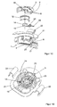
- die Einheit der
Figur 1A ohne das obere Gehäuseteil in einer perspektivischen Draufsicht von schräg oben, - Figur 2A
- eine perspektivische Ansicht einer erfindungsgemäßen Einheit gemäß einer zweiten Ausführungsform, und
Figur 2B- einen Schnitt entlang der
Schnittlinie 2B-2B inFigur 2A .
- Figure 1A
- a perspective view of a unit according to the invention according to a first embodiment,
- FIG. 1B
- a section along the
section line 1B-1B inFigure 1A . - Figure 1C
- the sectional view of
Figure 1 B in an exploded view, - FIG. 1D
- the unity of
Figure 1A without the upper housing part in a perspective top view obliquely from above, - FIG. 2A
- a perspective view of a unit according to the invention according to a second embodiment, and
- FIG. 2B
- a section along the
section line 2B-2B inFIG. 2A ,
Die Einheit für die Sitzbelegungserkennung eines Fahrzeugsitzes gemäß einer ersten Ausführungsform, wie sie in den
Der mögliche Verschiebeweg der beiden Gehäuseteile 2 und 3 zueinander ist begrenzt. Hierzu greift eine umlaufende Seitenwand 6 des unteren Gehäuseteils 3 in eine umlaufende Nut 7, die durch zwei umlaufende Seitenwände 8 des oberen Gehäuseteils 2 gebildet ist, ein. Dadurch können die beiden Gehäuseteile 2 und 3 nur soweit zusammengeschoben werden, bis die Stirnfläche der Seitenwand 6 des unteren Gehäuseteils 3 an die Bodenfläche 5 der umlaufenden Nut 7 anschlägt. In der anderen Richtung ist der maximale Verschiebeweg des oberen Gehäuseteils 2 zu dem unteren Gehäuseteil 3 durch mindestens zwei Laschen 9 begrenzt, die an der Außenseite der Seitenwand 6 des unteren Gehäuseteils 3 anliegen und jeweils ein Fenster 10 aufweisen, in das sich ein Vorsprung 11 an der Außenseite der Seitenwand 6 hinein erstreckt. Die Vorsprünge 11 besitzen eine Länge, in Richtung der Achse 4 gesehen, die geringer ist als die Öffnungsweite des jeweiligen Fensters 10 in dieser Richtung. Die Differenz zwischen dieser Länge der Vorsprünge 11 und der Öffnungsweite der Fenster 10 legt die Größe des möglichen Verschiebewegs des oberen Gehäuseteils 2 zu dem unteren Gehäuseteil 3 fest.The possible displacement of the two
In dem Innenraum des Gehäuses 1 ist eine Schraubenfeder 12 eingesetzt, die sich auf der Bodenfläche 5 des unteren Gehäuseteils 3 einerseits und an der Deckenfläche 13 des oberen Gehäuseteils 2 abstützt. Diese Schraubenfeder 12 besitzt einen Durchmesser, der annähernd dem Innendurchmesser des Innenraums des Gehäuses angepasst ist. Diese Schraubenfeder 12 ist so ausgelegt, dass sie in einer Ausgangsstellung die beiden Gehäuseteile 2 und 3 unter maximalem Abstand zueinander halten.In the interior of the
Auf der Bodenfläche 5 des unteren Gehäuseteils 3 befindet sich ein Mikroschalter 14, der nur schematisch dargestellt ist. Dieser Mikroschalter 14 ist nicht unmittelbar auf der Bodenfläche 5 montiert, sondern über eine Trägerplatte 15, die als Leiterplatte ausgeführt ist. Auf diese Trägerplatte bzw. Leiterplatte 15 ist der Mikroschalter 14 als Leiterplattenbauteil aufgelötet. Gleichzeitig befinden sich an dieser Leiterplatte 15 Anschlussstifte 16, die die Leiterbahnen der Leiterplatte zur Außenseite des Gehäuses 1 hin, und dort in einem Verbindungselement 17 als Teil des Gehäuses 1 endend, verbinden. Wie weiterhin anhand der
Die Trägerplatte bzw. Leiterplatte 15, auf der der Mikroschalter 14 angeordnet ist, bildet eine stabile Auflage für den Mikroschalter 14. Die Abmessungen dieser Platte 15 liegen im Bereich von 6 mm bis 30 mm, wobei die Grundfläche des Mikroschalters 14 weniger als 30% der Fläche der Platte 15 belegt.The support plate or printed
Die Platte 15 besitzt eine Länge, in Richtung des Anschlussstifts 16 gesehen (siehe
Um die Einheit, wie sie in den Figuren dargestellt ist, in einem Fahrzeugsitz, beispielsweise an einer gitterförmigen Tragekonstruktion des Sitzes, zu befestigen, ist das Gehäuse 1 durch einen Rahmen 21, vorzugsweise aus Metall, umgeben, der an geeigneten Stellen Klammern 22 zum Eingreifen in Teile der Tragekonstruktion umfasst.In order to secure the unit, as shown in the figures, in a vehicle seat, for example on a latticed support structure of the seat, the
Die als Leiterplatte 15 ausgeführte Trägerplatte, um den Mikroschalter 14 aufzunehmen, hat den Vorteil, dass diese Leiterplatte 15 mit weiteren diskreten Bauteilen, wie beispielsweise mit mindestens einem Widerstand 23, bestückt werden kann, ohne dass hierzu weitere Befestigungs- und/oder Halteelemente notwendig sind. Ein solcher Widerstand 23 wird in der Anordnung, wie sie hier beschrieben wird, dazu verwendet, in einer passenden Schaltungseinheit den Funktionszustand des Mikroschalters zu überprüfen.The designed as a
Während die
Um den Mikroschalter 14 mit der Leiterplatte 15 als Trägerplatte auf der Bodenfläche 5 des unteren Gehäuseteils 3 zu montieren, wird die Leiterplatte 15 mit den von der Unterseite vorstehenden Anschlussstiften 16 durch entsprechende Bohrungen, die in den
An dieser Stelle ist darauf hinzuweisen, dass in den beiden Ausführungsformen, wie sie in den Figuren dargestellt sind, Bauteile, die in ihrer Funktion in beiden Ausführungsformen vergleichbar sind, mit denselben Bezugszeichen versehen, so dass Angaben zu einer Ausführungsform auf die entsprechenden Bauteile der anderen Ausführungsform übertragen werden können, ohne dass dies ausdrücklich erwähnt ist. Auch können die Begriffe "oberes Gehäuseteil" und "unteres Gehäuseteil" in Abhängigkeit davon, in welcher Orientierung das Gehäuse in einem Sitz eingebaut wird, ausgetauscht werden.It should be noted that in the two embodiments, as shown in the figures, components which are similar in function in both embodiments, provided with the same reference numerals, so that information on an embodiment can be transferred to the corresponding components of the other embodiment, without this being explicitly mentioned. Also, the terms "upper case" and "lower case" may be interchanged depending on the orientation in which the case is installed in a seat.
Die Federkraft der Feder 12 ist so ausgelegt, dass die beiden Gehäuseteile 2 und 3 erst gegeneinander verschoben werden können, wenn die durch die Feder 12 ausgeübte Federkraft überwunden wird. Erst dann kann das Auslöseelement 18 mit dem Mikroschalter 14 in Kontakt gelangen. Um ein Auslösen des Schaltkontakts zu erreichen, ist die Einheit über die Feder 12 so ausgelegt, dass auf das Gehäuse ein Gewicht von mindestens 500 Gramm, vorzugsweise von 1000 Gramm bis 2500 Gramm, besonders bevorzugt von 1000 Gramm bis 1500 Gramm, einwirken muss. Unterhalb dieser Schwelle wird davon ausgegangen, dass noch keine Person auf dem Sitz Platz genommen hat.The spring force of the
Um dem Schaltverhalten des Mikroschalters 14 eine Hysterese aufzuerlegen, sollte das Schaltelement mit dem mindestens einen Mikroschalter 14, ausgehend von der Ausgangsstellung, mindestens zwei Schaltzustände aufweisen. Vorzugsweise werden hierzu zwei Mikroschalter 14 vorgesehen; jeder der beiden Mikroschalter besitzt dann eine unterschiedliche Auslöseschwelle, um einen Schaltzustand (ein oder aus) vorzunehmen.In order to impose a hysteresis on the switching behavior of the
Diese unterschiedlichen Auslöseschwellen können auch dadurch erreicht werden, dass in dem Gehäuse 1 zwei unterschiedliche Federn eingesetzt sind und die unterschiedlichen Auslöseschwellen durch die jeweilige Federkraft der zwei Federn festgelegt sind.These different triggering thresholds can also be achieved in that in the
In dem Gehäuse 1 wird bevorzugt auch eine Auswerteeinheit eingesetzt, die die Signale des Schaltelements unmittelbar verarbeitet. Dadurch sind nur kurze Verbindungen zwischen der Auswerteeinheit und dem Mikroschalter innerhalb des Gehäuses 1 erforderlich, wodurch die Handhabung der Einheit vereinfacht wird.In the
Weiterhin kann in dem Gehäuse 1 ein Temperatursensor, der nicht näher dargestellt ist, integriert werden, vorzugsweise als diskretes Bauteil auf der Leiterplatte 15. Über diesen Temperatursensor wird die Temperatur im Bereich der Einheit ermittelt, um diesen Temperaturwert zur Korrektur des Auslösepunkts des Mikroschalters bei starken Temperaturschwankungen innerhalb des Fahrzeugs heranzuziehen. Es wurde nämlich festgestellt, dass die Temperatur im Fahrzeug die Auslöseschwelle des Schaltelements stark beeinflussen kann, beispielsweise auch dadurch, dass sich bei den unterschiedlichen Temperaturen die Stauchhärte des Sitzpolsters ändert.Furthermore, in the
Claims (15)
Applications Claiming Priority (1)
| Application Number | Priority Date | Filing Date | Title |
|---|---|---|---|
| DE201320010948 DE202013010948U1 (en) | 2013-12-10 | 2013-12-10 | Unit for seat occupancy recognition of a vehicle seat |
Publications (2)
| Publication Number | Publication Date |
|---|---|
| EP2883741A1 true EP2883741A1 (en) | 2015-06-17 |
| EP2883741B1 EP2883741B1 (en) | 2018-02-07 |
Family
ID=52020888
Family Applications (1)
| Application Number | Title | Priority Date | Filing Date |
|---|---|---|---|
| EP14004050.2A Active EP2883741B1 (en) | 2013-12-10 | 2014-12-02 | Unit for occupant detection for a vehicle seat |
Country Status (2)
| Country | Link |
|---|---|
| EP (1) | EP2883741B1 (en) |
| DE (2) | DE202013010948U1 (en) |
Families Citing this family (1)
| Publication number | Priority date | Publication date | Assignee | Title |
|---|---|---|---|---|
| JP2018177048A (en) * | 2017-04-17 | 2018-11-15 | アイシン精機株式会社 | Seating detection device |
Citations (6)
| Publication number | Priority date | Publication date | Assignee | Title |
|---|---|---|---|---|
| US4795865A (en) * | 1987-12-10 | 1989-01-03 | Delta Systems, Inc. | Safety switch for automatic de-activation of a motor vehicle |
| US5424502A (en) * | 1993-07-27 | 1995-06-13 | Delta Systems, Inc. | Quick-install seat switch |
| DE102004031143A1 (en) | 2003-06-26 | 2005-04-14 | Lear Corp., Southfield | Spring sensor arrangement for a vehicle seat cushion |
| DE102006011015A1 (en) | 2005-03-22 | 2006-10-05 | Lear Corp., Southfield | Vehicle occupant detection system with a restraining member for a biasing member |
| DE102010043417A1 (en) | 2010-11-04 | 2012-05-10 | Mayser Gmbh & Co. Kg | Seat occupancy switch and vehicle seat |
| DE102010043416A1 (en) | 2010-11-04 | 2012-05-10 | Mayser Gmbh & Co. Kg | vehicle seat |
-
2013
- 2013-12-10 DE DE201320010948 patent/DE202013010948U1/en not_active Expired - Lifetime
-
2014
- 2014-12-02 DE DE102014017723.8A patent/DE102014017723A1/en not_active Withdrawn
- 2014-12-02 EP EP14004050.2A patent/EP2883741B1/en active Active
Patent Citations (6)
| Publication number | Priority date | Publication date | Assignee | Title |
|---|---|---|---|---|
| US4795865A (en) * | 1987-12-10 | 1989-01-03 | Delta Systems, Inc. | Safety switch for automatic de-activation of a motor vehicle |
| US5424502A (en) * | 1993-07-27 | 1995-06-13 | Delta Systems, Inc. | Quick-install seat switch |
| DE102004031143A1 (en) | 2003-06-26 | 2005-04-14 | Lear Corp., Southfield | Spring sensor arrangement for a vehicle seat cushion |
| DE102006011015A1 (en) | 2005-03-22 | 2006-10-05 | Lear Corp., Southfield | Vehicle occupant detection system with a restraining member for a biasing member |
| DE102010043417A1 (en) | 2010-11-04 | 2012-05-10 | Mayser Gmbh & Co. Kg | Seat occupancy switch and vehicle seat |
| DE102010043416A1 (en) | 2010-11-04 | 2012-05-10 | Mayser Gmbh & Co. Kg | vehicle seat |
Also Published As
| Publication number | Publication date |
|---|---|
| DE202013010948U1 (en) | 2015-03-11 |
| DE102014017723A1 (en) | 2015-06-11 |
| EP2883741B1 (en) | 2018-02-07 |
Similar Documents
| Publication | Publication Date | Title |
|---|---|---|
| DE2347722B2 (en) | PUSH BUTTON SWITCH | |
| DE2744206A1 (en) | CAPACITIVE KEY FOR KEYPAD | |
| WO2014167076A1 (en) | Device for operating multiple functions in a motor vehicle | |
| EP2795799A1 (en) | Operating device | |
| EP2450229A2 (en) | Seat occupation switch and vehicle seat | |
| EP2326534A1 (en) | Horn module for a vehicle steering wheel and vehicle steering wheel | |
| EP2984668A1 (en) | Device for operating multiple functions in a motor vehicle | |
| EP2883741B1 (en) | Unit for occupant detection for a vehicle seat | |
| DE102020005342A1 (en) | Electromagnetic relay | |
| DE202016104021U1 (en) | Seat occupancy sensor unit and seat | |
| DE102016203560A1 (en) | Sensor module for an actuator with displaceable armature and actuator arrangement | |
| DE102007003567A1 (en) | Belt buckle for a safety belt | |
| CH702088A2 (en) | Buckle with a switch arrangement for detecting the locking state. | |
| EP2650897B1 (en) | Temperature-sensitive electrical switch and method for producing the same | |
| DE102015219348B3 (en) | BUTTON FOR A CONTACT DEVICE | |
| EP4014244B1 (en) | Electric push-button switch | |
| EP3413465B1 (en) | Operating device for operating least one device of a motor vehicle, with a separate spring element as earthing connection and motor vehicle | |
| DE102022107300B3 (en) | Device for detecting a keystroke, keyboard | |
| DE19941500A1 (en) | Automobile seat connector arrangement has first and second protrusions forming first and second contact surfaces at distance apart for direct or indirect connection of two conductors | |
| DE102019112680A1 (en) | Surge protection device | |
| DE10056656C2 (en) | Microswitch with increased contact force | |
| EP0620577B1 (en) | Electric pushbutton switch | |
| EP3450243B1 (en) | Device for mechanical control of an electric or electronic input unit | |
| EP3301697B1 (en) | Push-button switch | |
| DE102005014792A1 (en) | Load transducer with non-contact detector unit |
Legal Events
| Date | Code | Title | Description |
|---|---|---|---|
| PUAI | Public reference made under article 153(3) epc to a published international application that has entered the european phase |
Free format text: ORIGINAL CODE: 0009012 |
|
| 17P | Request for examination filed |
Effective date: 20141202 |
|
| AK | Designated contracting states |
Kind code of ref document: A1 Designated state(s): AL AT BE BG CH CY CZ DE DK EE ES FI FR GB GR HR HU IE IS IT LI LT LU LV MC MK MT NL NO PL PT RO RS SE SI SK SM TR |
|
| AX | Request for extension of the european patent |
Extension state: BA ME |
|
| R17P | Request for examination filed (corrected) |
Effective date: 20151215 |
|
| RBV | Designated contracting states (corrected) |
Designated state(s): AL AT BE BG CH CY CZ DE DK EE ES FI FR GB GR HR HU IE IS IT LI LT LU LV MC MK MT NL NO PL PT RO RS SE SI SK SM TR |
|
| RIC1 | Information provided on ipc code assigned before grant |
Ipc: B60N 2/00 20060101AFI20170630BHEP |
|
| GRAP | Despatch of communication of intention to grant a patent |
Free format text: ORIGINAL CODE: EPIDOSNIGR1 |
|
| INTG | Intention to grant announced |
Effective date: 20170831 |
|
| RIN1 | Information on inventor provided before grant (corrected) |
Inventor name: MICHELMANN, JOCHEN Inventor name: YETIM, ZUEHER |
|
| GRAS | Grant fee paid |
Free format text: ORIGINAL CODE: EPIDOSNIGR3 |
|
| GRAA | (expected) grant |
Free format text: ORIGINAL CODE: 0009210 |
|
| AK | Designated contracting states |
Kind code of ref document: B1 Designated state(s): AL AT BE BG CH CY CZ DE DK EE ES FI FR GB GR HR HU IE IS IT LI LT LU LV MC MK MT NL NO PL PT RO RS SE SI SK SM TR |
|
| REG | Reference to a national code |
Ref country code: GB Ref legal event code: FG4D Free format text: NOT ENGLISH |
|
| REG | Reference to a national code |
Ref country code: AT Ref legal event code: REF Ref document number: 968643 Country of ref document: AT Kind code of ref document: T Effective date: 20180215 Ref country code: CH Ref legal event code: EP |
|
| REG | Reference to a national code |
Ref country code: IE Ref legal event code: FG4D Free format text: LANGUAGE OF EP DOCUMENT: GERMAN |
|
| REG | Reference to a national code |
Ref country code: DE Ref legal event code: R096 Ref document number: 502014007187 Country of ref document: DE |
|
| REG | Reference to a national code |
Ref country code: SE Ref legal event code: TRGR |
|
| REG | Reference to a national code |
Ref country code: NL Ref legal event code: MP Effective date: 20180207 |
|
| PG25 | Lapsed in a contracting state [announced via postgrant information from national office to epo] |
Ref country code: LT Free format text: LAPSE BECAUSE OF FAILURE TO SUBMIT A TRANSLATION OF THE DESCRIPTION OR TO PAY THE FEE WITHIN THE PRESCRIBED TIME-LIMIT Effective date: 20180207 Ref country code: FI Free format text: LAPSE BECAUSE OF FAILURE TO SUBMIT A TRANSLATION OF THE DESCRIPTION OR TO PAY THE FEE WITHIN THE PRESCRIBED TIME-LIMIT Effective date: 20180207 Ref country code: HR Free format text: LAPSE BECAUSE OF FAILURE TO SUBMIT A TRANSLATION OF THE DESCRIPTION OR TO PAY THE FEE WITHIN THE PRESCRIBED TIME-LIMIT Effective date: 20180207 Ref country code: NO Free format text: LAPSE BECAUSE OF FAILURE TO SUBMIT A TRANSLATION OF THE DESCRIPTION OR TO PAY THE FEE WITHIN THE PRESCRIBED TIME-LIMIT Effective date: 20180507 Ref country code: ES Free format text: LAPSE BECAUSE OF FAILURE TO SUBMIT A TRANSLATION OF THE DESCRIPTION OR TO PAY THE FEE WITHIN THE PRESCRIBED TIME-LIMIT Effective date: 20180207 Ref country code: NL Free format text: LAPSE BECAUSE OF FAILURE TO SUBMIT A TRANSLATION OF THE DESCRIPTION OR TO PAY THE FEE WITHIN THE PRESCRIBED TIME-LIMIT Effective date: 20180207 Ref country code: CY Free format text: LAPSE BECAUSE OF FAILURE TO SUBMIT A TRANSLATION OF THE DESCRIPTION OR TO PAY THE FEE WITHIN THE PRESCRIBED TIME-LIMIT Effective date: 20180207 |
|
| PG25 | Lapsed in a contracting state [announced via postgrant information from national office to epo] |
Ref country code: PL Free format text: LAPSE BECAUSE OF FAILURE TO SUBMIT A TRANSLATION OF THE DESCRIPTION OR TO PAY THE FEE WITHIN THE PRESCRIBED TIME-LIMIT Effective date: 20180207 Ref country code: RS Free format text: LAPSE BECAUSE OF FAILURE TO SUBMIT A TRANSLATION OF THE DESCRIPTION OR TO PAY THE FEE WITHIN THE PRESCRIBED TIME-LIMIT Effective date: 20180207 Ref country code: LV Free format text: LAPSE BECAUSE OF FAILURE TO SUBMIT A TRANSLATION OF THE DESCRIPTION OR TO PAY THE FEE WITHIN THE PRESCRIBED TIME-LIMIT Effective date: 20180207 Ref country code: IS Free format text: LAPSE BECAUSE OF FAILURE TO SUBMIT A TRANSLATION OF THE DESCRIPTION OR TO PAY THE FEE WITHIN THE PRESCRIBED TIME-LIMIT Effective date: 20180607 Ref country code: GR Free format text: LAPSE BECAUSE OF FAILURE TO SUBMIT A TRANSLATION OF THE DESCRIPTION OR TO PAY THE FEE WITHIN THE PRESCRIBED TIME-LIMIT Effective date: 20180508 Ref country code: BG Free format text: LAPSE BECAUSE OF FAILURE TO SUBMIT A TRANSLATION OF THE DESCRIPTION OR TO PAY THE FEE WITHIN THE PRESCRIBED TIME-LIMIT Effective date: 20180507 |
|
| PG25 | Lapsed in a contracting state [announced via postgrant information from national office to epo] |
Ref country code: MT Free format text: LAPSE BECAUSE OF FAILURE TO SUBMIT A TRANSLATION OF THE DESCRIPTION OR TO PAY THE FEE WITHIN THE PRESCRIBED TIME-LIMIT Effective date: 20180207 |
|
| PG25 | Lapsed in a contracting state [announced via postgrant information from national office to epo] |
Ref country code: EE Free format text: LAPSE BECAUSE OF FAILURE TO SUBMIT A TRANSLATION OF THE DESCRIPTION OR TO PAY THE FEE WITHIN THE PRESCRIBED TIME-LIMIT Effective date: 20180207 Ref country code: AL Free format text: LAPSE BECAUSE OF FAILURE TO SUBMIT A TRANSLATION OF THE DESCRIPTION OR TO PAY THE FEE WITHIN THE PRESCRIBED TIME-LIMIT Effective date: 20180207 Ref country code: RO Free format text: LAPSE BECAUSE OF FAILURE TO SUBMIT A TRANSLATION OF THE DESCRIPTION OR TO PAY THE FEE WITHIN THE PRESCRIBED TIME-LIMIT Effective date: 20180207 |
|
| REG | Reference to a national code |
Ref country code: DE Ref legal event code: R097 Ref document number: 502014007187 Country of ref document: DE |
|
| PG25 | Lapsed in a contracting state [announced via postgrant information from national office to epo] |
Ref country code: CZ Free format text: LAPSE BECAUSE OF FAILURE TO SUBMIT A TRANSLATION OF THE DESCRIPTION OR TO PAY THE FEE WITHIN THE PRESCRIBED TIME-LIMIT Effective date: 20180207 Ref country code: SK Free format text: LAPSE BECAUSE OF FAILURE TO SUBMIT A TRANSLATION OF THE DESCRIPTION OR TO PAY THE FEE WITHIN THE PRESCRIBED TIME-LIMIT Effective date: 20180207 Ref country code: SM Free format text: LAPSE BECAUSE OF FAILURE TO SUBMIT A TRANSLATION OF THE DESCRIPTION OR TO PAY THE FEE WITHIN THE PRESCRIBED TIME-LIMIT Effective date: 20180207 Ref country code: DK Free format text: LAPSE BECAUSE OF FAILURE TO SUBMIT A TRANSLATION OF THE DESCRIPTION OR TO PAY THE FEE WITHIN THE PRESCRIBED TIME-LIMIT Effective date: 20180207 |
|
| PLBE | No opposition filed within time limit |
Free format text: ORIGINAL CODE: 0009261 |
|
| STAA | Information on the status of an ep patent application or granted ep patent |
Free format text: STATUS: NO OPPOSITION FILED WITHIN TIME LIMIT |
|
| 26N | No opposition filed |
Effective date: 20181108 |
|
| PG25 | Lapsed in a contracting state [announced via postgrant information from national office to epo] |
Ref country code: SI Free format text: LAPSE BECAUSE OF FAILURE TO SUBMIT A TRANSLATION OF THE DESCRIPTION OR TO PAY THE FEE WITHIN THE PRESCRIBED TIME-LIMIT Effective date: 20180207 |
|
| REG | Reference to a national code |
Ref country code: CH Ref legal event code: PL |
|
| PG25 | Lapsed in a contracting state [announced via postgrant information from national office to epo] |
Ref country code: MC Free format text: LAPSE BECAUSE OF FAILURE TO SUBMIT A TRANSLATION OF THE DESCRIPTION OR TO PAY THE FEE WITHIN THE PRESCRIBED TIME-LIMIT Effective date: 20180207 Ref country code: LU Free format text: LAPSE BECAUSE OF NON-PAYMENT OF DUE FEES Effective date: 20181202 |
|
| REG | Reference to a national code |
Ref country code: IE Ref legal event code: MM4A |
|
| REG | Reference to a national code |
Ref country code: BE Ref legal event code: MM Effective date: 20181231 |
|
| PG25 | Lapsed in a contracting state [announced via postgrant information from national office to epo] |
Ref country code: IE Free format text: LAPSE BECAUSE OF NON-PAYMENT OF DUE FEES Effective date: 20181202 |
|
| PG25 | Lapsed in a contracting state [announced via postgrant information from national office to epo] |
Ref country code: BE Free format text: LAPSE BECAUSE OF NON-PAYMENT OF DUE FEES Effective date: 20181231 |
|
| PG25 | Lapsed in a contracting state [announced via postgrant information from national office to epo] |
Ref country code: LI Free format text: LAPSE BECAUSE OF NON-PAYMENT OF DUE FEES Effective date: 20181231 Ref country code: CH Free format text: LAPSE BECAUSE OF NON-PAYMENT OF DUE FEES Effective date: 20181231 |
|
| PG25 | Lapsed in a contracting state [announced via postgrant information from national office to epo] |
Ref country code: TR Free format text: LAPSE BECAUSE OF FAILURE TO SUBMIT A TRANSLATION OF THE DESCRIPTION OR TO PAY THE FEE WITHIN THE PRESCRIBED TIME-LIMIT Effective date: 20180207 |
|
| PG25 | Lapsed in a contracting state [announced via postgrant information from national office to epo] |
Ref country code: PT Free format text: LAPSE BECAUSE OF FAILURE TO SUBMIT A TRANSLATION OF THE DESCRIPTION OR TO PAY THE FEE WITHIN THE PRESCRIBED TIME-LIMIT Effective date: 20180207 |
|
| PG25 | Lapsed in a contracting state [announced via postgrant information from national office to epo] |
Ref country code: MK Free format text: LAPSE BECAUSE OF NON-PAYMENT OF DUE FEES Effective date: 20180207 Ref country code: HU Free format text: LAPSE BECAUSE OF FAILURE TO SUBMIT A TRANSLATION OF THE DESCRIPTION OR TO PAY THE FEE WITHIN THE PRESCRIBED TIME-LIMIT; INVALID AB INITIO Effective date: 20141202 |
|
| REG | Reference to a national code |
Ref country code: AT Ref legal event code: MM01 Ref document number: 968643 Country of ref document: AT Kind code of ref document: T Effective date: 20191202 |
|
| PG25 | Lapsed in a contracting state [announced via postgrant information from national office to epo] |
Ref country code: AT Free format text: LAPSE BECAUSE OF NON-PAYMENT OF DUE FEES Effective date: 20191202 |
|
| PGFP | Annual fee paid to national office [announced via postgrant information from national office to epo] |
Ref country code: GB Payment date: 20231219 Year of fee payment: 10 |
|
| PGFP | Annual fee paid to national office [announced via postgrant information from national office to epo] |
Ref country code: SE Payment date: 20231222 Year of fee payment: 10 Ref country code: IT Payment date: 20231221 Year of fee payment: 10 Ref country code: FR Payment date: 20231226 Year of fee payment: 10 Ref country code: DE Payment date: 20230810 Year of fee payment: 10 |