EP2883731B1 - Disconnector for hybrid vehicle - Google Patents
Disconnector for hybrid vehicle Download PDFInfo
- Publication number
- EP2883731B1 EP2883731B1 EP13197375.2A EP13197375A EP2883731B1 EP 2883731 B1 EP2883731 B1 EP 2883731B1 EP 13197375 A EP13197375 A EP 13197375A EP 2883731 B1 EP2883731 B1 EP 2883731B1
- Authority
- EP
- European Patent Office
- Prior art keywords
- shift fork
- disconnector
- input shaft
- hub
- upper housing
- Prior art date
- Legal status (The legal status is an assumption and is not a legal conclusion. Google has not performed a legal analysis and makes no representation as to the accuracy of the status listed.)
- Active
Links
Images

Classifications
-
- B—PERFORMING OPERATIONS; TRANSPORTING
- B60—VEHICLES IN GENERAL
- B60K—ARRANGEMENT OR MOUNTING OF PROPULSION UNITS OR OF TRANSMISSIONS IN VEHICLES; ARRANGEMENT OR MOUNTING OF PLURAL DIVERSE PRIME-MOVERS IN VEHICLES; AUXILIARY DRIVES FOR VEHICLES; INSTRUMENTATION OR DASHBOARDS FOR VEHICLES; ARRANGEMENTS IN CONNECTION WITH COOLING, AIR INTAKE, GAS EXHAUST OR FUEL SUPPLY OF PROPULSION UNITS IN VEHICLES
- B60K6/00—Arrangement or mounting of plural diverse prime-movers for mutual or common propulsion, e.g. hybrid propulsion systems comprising electric motors and internal combustion engines
- B60K6/20—Arrangement or mounting of plural diverse prime-movers for mutual or common propulsion, e.g. hybrid propulsion systems comprising electric motors and internal combustion engines the prime-movers consisting of electric motors and internal combustion engines, e.g. HEVs
- B60K6/50—Architecture of the driveline characterised by arrangement or kind of transmission units
- B60K6/52—Driving a plurality of drive axles, e.g. four-wheel drive
-
- F—MECHANICAL ENGINEERING; LIGHTING; HEATING; WEAPONS; BLASTING
- F16—ENGINEERING ELEMENTS AND UNITS; GENERAL MEASURES FOR PRODUCING AND MAINTAINING EFFECTIVE FUNCTIONING OF MACHINES OR INSTALLATIONS; THERMAL INSULATION IN GENERAL
- F16H—GEARING
- F16H57/00—General details of gearing
- F16H57/02—Gearboxes; Mounting gearing therein
-
- B—PERFORMING OPERATIONS; TRANSPORTING
- B60—VEHICLES IN GENERAL
- B60K—ARRANGEMENT OR MOUNTING OF PROPULSION UNITS OR OF TRANSMISSIONS IN VEHICLES; ARRANGEMENT OR MOUNTING OF PLURAL DIVERSE PRIME-MOVERS IN VEHICLES; AUXILIARY DRIVES FOR VEHICLES; INSTRUMENTATION OR DASHBOARDS FOR VEHICLES; ARRANGEMENTS IN CONNECTION WITH COOLING, AIR INTAKE, GAS EXHAUST OR FUEL SUPPLY OF PROPULSION UNITS IN VEHICLES
- B60K6/00—Arrangement or mounting of plural diverse prime-movers for mutual or common propulsion, e.g. hybrid propulsion systems comprising electric motors and internal combustion engines
- B60K6/20—Arrangement or mounting of plural diverse prime-movers for mutual or common propulsion, e.g. hybrid propulsion systems comprising electric motors and internal combustion engines the prime-movers consisting of electric motors and internal combustion engines, e.g. HEVs
- B60K6/22—Arrangement or mounting of plural diverse prime-movers for mutual or common propulsion, e.g. hybrid propulsion systems comprising electric motors and internal combustion engines the prime-movers consisting of electric motors and internal combustion engines, e.g. HEVs characterised by apparatus, components or means specially adapted for HEVs
- B60K6/38—Arrangement or mounting of plural diverse prime-movers for mutual or common propulsion, e.g. hybrid propulsion systems comprising electric motors and internal combustion engines the prime-movers consisting of electric motors and internal combustion engines, e.g. HEVs characterised by apparatus, components or means specially adapted for HEVs characterised by the driveline clutches
-
- B—PERFORMING OPERATIONS; TRANSPORTING
- B60—VEHICLES IN GENERAL
- B60K—ARRANGEMENT OR MOUNTING OF PROPULSION UNITS OR OF TRANSMISSIONS IN VEHICLES; ARRANGEMENT OR MOUNTING OF PLURAL DIVERSE PRIME-MOVERS IN VEHICLES; AUXILIARY DRIVES FOR VEHICLES; INSTRUMENTATION OR DASHBOARDS FOR VEHICLES; ARRANGEMENTS IN CONNECTION WITH COOLING, AIR INTAKE, GAS EXHAUST OR FUEL SUPPLY OF PROPULSION UNITS IN VEHICLES
- B60K6/00—Arrangement or mounting of plural diverse prime-movers for mutual or common propulsion, e.g. hybrid propulsion systems comprising electric motors and internal combustion engines
- B60K6/20—Arrangement or mounting of plural diverse prime-movers for mutual or common propulsion, e.g. hybrid propulsion systems comprising electric motors and internal combustion engines the prime-movers consisting of electric motors and internal combustion engines, e.g. HEVs
- B60K6/22—Arrangement or mounting of plural diverse prime-movers for mutual or common propulsion, e.g. hybrid propulsion systems comprising electric motors and internal combustion engines the prime-movers consisting of electric motors and internal combustion engines, e.g. HEVs characterised by apparatus, components or means specially adapted for HEVs
- B60K6/38—Arrangement or mounting of plural diverse prime-movers for mutual or common propulsion, e.g. hybrid propulsion systems comprising electric motors and internal combustion engines the prime-movers consisting of electric motors and internal combustion engines, e.g. HEVs characterised by apparatus, components or means specially adapted for HEVs characterised by the driveline clutches
- B60K6/387—Actuated clutches, i.e. clutches engaged or disengaged by electric, hydraulic or mechanical actuating means
-
- F—MECHANICAL ENGINEERING; LIGHTING; HEATING; WEAPONS; BLASTING
- F16—ENGINEERING ELEMENTS AND UNITS; GENERAL MEASURES FOR PRODUCING AND MAINTAINING EFFECTIVE FUNCTIONING OF MACHINES OR INSTALLATIONS; THERMAL INSULATION IN GENERAL
- F16H—GEARING
- F16H59/00—Control inputs to control units of change-speed- or reversing-gearings for conveying rotary motion
- F16H59/68—Inputs being a function of gearing status
- F16H59/70—Inputs being a function of gearing status dependent on the ratio established
-
- F—MECHANICAL ENGINEERING; LIGHTING; HEATING; WEAPONS; BLASTING
- F16—ENGINEERING ELEMENTS AND UNITS; GENERAL MEASURES FOR PRODUCING AND MAINTAINING EFFECTIVE FUNCTIONING OF MACHINES OR INSTALLATIONS; THERMAL INSULATION IN GENERAL
- F16H—GEARING
- F16H63/00—Control outputs from the control unit to change-speed- or reversing-gearings for conveying rotary motion or to other devices than the final output mechanism
- F16H63/02—Final output mechanisms therefor; Actuating means for the final output mechanisms
- F16H63/30—Constructional features of the final output mechanisms
- F16H63/304—Constructional features of the final output mechanisms the final output mechanisms comprising elements moved by electrical or magnetic force
-
- F—MECHANICAL ENGINEERING; LIGHTING; HEATING; WEAPONS; BLASTING
- F16—ENGINEERING ELEMENTS AND UNITS; GENERAL MEASURES FOR PRODUCING AND MAINTAINING EFFECTIVE FUNCTIONING OF MACHINES OR INSTALLATIONS; THERMAL INSULATION IN GENERAL
- F16H—GEARING
- F16H63/00—Control outputs from the control unit to change-speed- or reversing-gearings for conveying rotary motion or to other devices than the final output mechanism
- F16H63/02—Final output mechanisms therefor; Actuating means for the final output mechanisms
- F16H63/30—Constructional features of the final output mechanisms
- F16H63/304—Constructional features of the final output mechanisms the final output mechanisms comprising elements moved by electrical or magnetic force
- F16H2063/3063—Constructional features of the final output mechanisms the final output mechanisms comprising elements moved by electrical or magnetic force using screw devices
-
- Y—GENERAL TAGGING OF NEW TECHNOLOGICAL DEVELOPMENTS; GENERAL TAGGING OF CROSS-SECTIONAL TECHNOLOGIES SPANNING OVER SEVERAL SECTIONS OF THE IPC; TECHNICAL SUBJECTS COVERED BY FORMER USPC CROSS-REFERENCE ART COLLECTIONS [XRACs] AND DIGESTS
- Y02—TECHNOLOGIES OR APPLICATIONS FOR MITIGATION OR ADAPTATION AGAINST CLIMATE CHANGE
- Y02T—CLIMATE CHANGE MITIGATION TECHNOLOGIES RELATED TO TRANSPORTATION
- Y02T10/00—Road transport of goods or passengers
- Y02T10/60—Other road transportation technologies with climate change mitigation effect
- Y02T10/62—Hybrid vehicles
Definitions
- the present invention relates to a disconnector for a hybrid vehicle, and more particularly, to a disconnector for a hybrid vehicle, which can accurately control interruption or transmission of rotary power by accurately measuring and monitoring a transfer distance of a shift fork using a linear sensor while interrupting or transmitting the rotary power of an engine or a motor using the shift fork.
- the hybrid vehicle includes an engine generating rotary power by fossil fuel and a driving motor generating rotary power by electricity and is configured to interrupt or transmit the rotary power of the engine according to the necessity.
- the conventional hybrid vehicle uses a clutch to interrupt or transmit the rotary power of the engine, the efficiency of the engine may be lowered.
- a split axle drive mechanism for part-time four-wheel drive vehicle ( US 4625584 ).
- This mechanism comprises a disconnector with the features of the preamble of claim 1, more specifically a clutch mechanism disengageable for disconnecting the first axle shaft from the first output member when the vehicle is in a two-wheel drive mode and engageable for connecting the first exit shaft to the first output member when the vehicle is in the four-wheel drive mode.
- An actuator is provided to shift a shift fork between two positions. Both positions can be detected by a sensing arrangement.
- An activator with a linearly movable drive screw as part of a vehicle system is also known ( US 2010/0242642 A1 ). This activator can be used in the drive system of a vehicle. Both end positions of the drive screw can be detected by a noncontact position sensing system.
- the present invention provides a disconnector for a hybrid vehicle, which can accurately control interruption or transmission of rotary power by accurately measuring and monitoring a transfer distance of a shift fork using a linear sensor while interrupting or transmitting the rotary power of an engine or a motor using the shift fork.
- a disconnector in accordance with the present invention, there is provided a disconnector according to claim 1, that includes an upper housing connected to a reducer, an input shaft installed inside the upper housing and transmitting rotary power of the reducer, bearings installed between the upper housing and the input shaft, a hub disposed under the input shaft, a sleeve having an inner circumferential surface spline-coupled to outer circumferential surfaces of the input shaft and the hub to then be shifted to transmit or interrupt the rotary power of the input shaft to the hub, a shift fork coupled to an outer circumferential surface of the sleeve and shifting the sleeve, a first spring installed between the upper housing and the shift fork, a lower case connected to a lower portion of the upper housing, a constant velocity joint connected to the hub through the inside of the lower case, a needle roller installed between the lower case and the constant velocity joint, an actuator coupled to the inside of the lower case and pushing out the shift fork, and a linear sensor sensing a transfer distance of the shift
- the actuator may include a motor generating rotary power, a lead screw converting a rotary motion into a linear motion, a cover mounted at a front end of the lead screw, a second spring installed between the lead screw and the cover, and a position sensor installed to be spaced apart from one side of the lead screw.
- the disconnector may further include a controller controlling a motor of the actuator of the motor according to the transfer distance of the shift fork measured by the linear sensor.
- the motor may be a reversible motor.
- the shift fork may have an inclined surface formed at a region positioned to correspond to the linear sensor.
- interruption or transmission of rotary power can be accurately controlled by accurately measuring and monitoring a transfer distance of a shift fork using a linear sensor while interrupting or transmitting the rotary power of an engine or a motor using the shift fork.
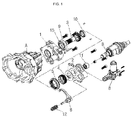
- FIG. 1 is a perspective view illustrating an assembled state of a disconnector for a hybrid vehicle according to an embodiment of the present invention
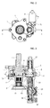
- FIG. 2 is a front view of the disconnector for a hybrid vehicle shown in FIG. 1
- FIG. 3 is a cross-sectional view taken along the line A-A of FIG. 2
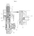
- FIG. 4 is a cross-sectional view taken along the line B-B of FIG. 2 , illustrating a case of interrupting power
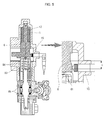
- FIG. 5 is a cross-sectional view taken along the line B-B of FIG. 2 , illustrating a case of transmitting power.
- the disconnector for a hybrid vehicle includes an upper housing 1 connected to a reducer A, an input shaft 3 installed inside the upper housing 1 and transmitting rotary power of the reducer A, bearings 9 and 10 installed between the upper housing 1 and the input shaft 3, a hub 4 disposed under the input shaft 3, a sleeve 5 having an inner circumferential surface spline-coupled to outer circumferential surfaces of the input shaft 3 and the hub 4 to then be shifted to transmit or interrupt the rotary power of the input shaft 3 to the hub 4, a shift fork 6 coupled to an outer circumferential surface of the sleeve 5 and shifting the sleeve 5, a first spring 12 installed between the upper housing 1 and the shift fork 6, a lower case 2 connected to a lower portion of the upper housing 1, a constant velocity joint B connected to the hub 4 through the inside of the lower case 2, a needle roller 11 installed between the lower case 2 and the constant velocity joint B, an actuator 8 coupled to the
- the actuator 8 includes a motor 81 generating rotary power, a lead screw 82 converting a rotary motion of the motor 81 into a linear motion, a cover 84 mounted at a front end of the lead screw 82, a second spring 83 installed between the lead screw 82 and the cover 84, and a position sensor 85 installed to be spaced apart from one side of the lead screw 82.
- a reversible motor is used as the motor 81.
- FIG. 6 is a perspective view of a shift fork of the disconnector for a hybrid vehicle shown in FIG. 1 and FIG. 7 is a cross-sectional view taken along the line C-C of FIG. 6 .
- the shift fork 6 has an inclined surface 61 formed at a region positioned to correspond to the linear sensor 15.
- the aforementioned disconnector for a hybrid vehicle operates as follows.
- the rotary power is generated from the motor 81 and the lead screw 82 converts a rotary motion of a rotary shaft of the motor 81 into a linear motion to transfer the linear motion to the cover 84.
- a transfer completion position of the lead screw 82 is sensed by the position sensor 85.
- the cover 84 lifts the shift fork 6 while exhibiting a buffering action derived from an elastic force of the second spring 83. Accordingly, the shift fork 6 shifts the sleeve 5 coupled to the hub 4 toward the input shaft 3, thereby commonly coupling the sleeve 5 to the hub 4 and the input shaft 3.
- the linear sensor 15 is installed at a region corresponding to the inclined surface 61 of the shift fork 6 to measure a transfer distance of the shift fork 6, thereby accurately controlling the transfer distance of the shift fork 6.
- the lead screw 82 returns to its original position.
- the transfer completion position of the lead screw 82 is sensed by the position sensor 85.
- the shift fork 6 is pushed out by a restoring force of the first spring 12 installed between the upper housing 1 and the shift fork 6, thereby shifting the sleeve 5 commonly coupled to the hub 4 and the input shaft 3 to separate the hub 4 and the input shaft 3 from each other.
- the transfer distance of the shift fork 6 is measured by the linear sensor 15 installed at the region positioned to correspond to the inclined surface 61 of the shift fork 6, so that a controller(not shown) can accurately control the transfer distance of the shift fork 6.
Landscapes
- Engineering & Computer Science (AREA)
- General Engineering & Computer Science (AREA)
- Mechanical Engineering (AREA)
- Chemical & Material Sciences (AREA)
- Combustion & Propulsion (AREA)
- Transportation (AREA)
- Hybrid Electric Vehicles (AREA)
- Gear-Shifting Mechanisms (AREA)
- Electric Propulsion And Braking For Vehicles (AREA)
Description
- The present invention relates to a disconnector for a hybrid vehicle, and more particularly, to a disconnector for a hybrid vehicle, which can accurately control interruption or transmission of rotary power by accurately measuring and monitoring a transfer distance of a shift fork using a linear sensor while interrupting or transmitting the rotary power of an engine or a motor using the shift fork.
- As fossil fuels are running out, development of hybrid vehicles using a combination of fossil fuel and electricity, instead of vehicles using fossil fuel such as gasoline or diesel, is underway.
- The hybrid vehicle includes an engine generating rotary power by fossil fuel and a driving motor generating rotary power by electricity and is configured to interrupt or transmit the rotary power of the engine according to the necessity.
- A technique of using an engine clutch to interrupt the rotary power of the engine is disclosed in Korean Patent Publication No.
10-2009-0024915 (March 10, 2009 - However, since the conventional hybrid vehicle uses a clutch to interrupt or transmit the rotary power of the engine, the efficiency of the engine may be lowered.
- Furthermore is known a split axle drive mechanism for part-time four-wheel drive vehicle (
US 4625584 ). This mechanism comprises a disconnector with the features of the preamble ofclaim 1, more specifically a clutch mechanism disengageable for disconnecting the first axle shaft from the first output member when the vehicle is in a two-wheel drive mode and engageable for connecting the first exit shaft to the first output member when the vehicle is in the four-wheel drive mode. An actuator is provided to shift a shift fork between two positions. Both positions can be detected by a sensing arrangement. - An activator with a linearly movable drive screw as part of a vehicle system is also known (
US 2010/0242642 A1 ). This activator can be used in the drive system of a vehicle. Both end positions of the drive screw can be detected by a noncontact position sensing system. - The present invention provides a disconnector for a hybrid vehicle, which can accurately control interruption or transmission of rotary power by accurately measuring and monitoring a transfer distance of a shift fork using a linear sensor while interrupting or transmitting the rotary power of an engine or a motor using the shift fork.
- In accordance with the present invention, there is provided a disconnector according to
claim 1, that includes an upper housing connected to a reducer, an input shaft installed inside the upper housing and transmitting rotary power of the reducer, bearings installed between the upper housing and the input shaft, a hub disposed under the input shaft, a sleeve having an inner circumferential surface spline-coupled to outer circumferential surfaces of the input shaft and the hub to then be shifted to transmit or interrupt the rotary power of the input shaft to the hub, a shift fork coupled to an outer circumferential surface of the sleeve and shifting the sleeve, a first spring installed between the upper housing and the shift fork, a lower case connected to a lower portion of the upper housing, a constant velocity joint connected to the hub through the inside of the lower case, a needle roller installed between the lower case and the constant velocity joint, an actuator coupled to the inside of the lower case and pushing out the shift fork, and a linear sensor sensing a transfer distance of the shift fork. - The actuator may include a motor generating rotary power, a lead screw converting a rotary motion into a linear motion, a cover mounted at a front end of the lead screw, a second spring installed between the lead screw and the cover, and a position sensor installed to be spaced apart from one side of the lead screw.
- The disconnector may further include a controller controlling a motor of the actuator of the motor according to the transfer distance of the shift fork measured by the linear sensor.
- The motor may be a reversible motor.
- The shift fork may have an inclined surface formed at a region positioned to correspond to the linear sensor.
- As described above, according to the present invention, interruption or transmission of rotary power can be accurately controlled by accurately measuring and monitoring a transfer distance of a shift fork using a linear sensor while interrupting or transmitting the rotary power of an engine or a motor using the shift fork.
- Additional aspects and/or advantages of the invention will be set forth in part in the description which follows and, in part, will be obvious from the description, or may be learned by practice of the invention.
- The objects, features and advantages of the present invention will be more apparent from the following detailed description in conjunction with the accompanying drawings, in which:
-
FIG. 1 is a perspective view illustrating an assembled state of a disconnector for a hybrid vehicle according to an embodiment of the present invention; -
FIG. 2 is a front view of the disconnector for a hybrid vehicle shown inFIG. 1 ; -
FIG. 3 is a cross-sectional view taken along the line A-A ofFIG. 2 ; -
FIG. 4 is a cross-sectional view taken along the line B-B ofFIG. 2 , illustrating a case of interrupting power; -
FIG. 5 is a cross-sectional view taken along the line B-B ofFIG. 2 , illustrating a case of transmitting power; -
FIG. 6 is a perspective view of a shift fork of the disconnector for a hybrid vehicle shown inFIG. 1 ; and -
FIG. 7 is a cross-sectional view taken along the line C-C ofFIG. 6 . - Hereinafter, examples of embodiments of the invention will be described in detail with reference to the accompanying drawings such that they can easily be made and used by those skilled in the art. Advantages and features of the present invention and methods of accomplishing the same may be understood more readily by reference to the following detailed description of preferred embodiments and the accompanying drawings.
- However, the following descriptions of such embodiments are intended primarily for illustrating the principles and exemplary constructions of the present invention, and the present invention as defined in the appended claims is not specifically limited to these exemplary embodiments.
- In addition, it should be understood that the terms and words used in the specification and the appended claims should not be construed as limited to general and dictionary meanings, but interpreted based on the meanings and concepts corresponding to technical aspects of the present invention on the basis of the principle that the inventor is allowed to define terms appropriately for the best explanation for the invention. For the sake of convenience, an orientation is set on the basis of illustration of figures.
-
FIG. 1 is a perspective view illustrating an assembled state of a disconnector for a hybrid vehicle according to an embodiment of the present invention,FIG. 2 is a front view of the disconnector for a hybrid vehicle shown inFIG. 1 ,FIG. 3 is a cross-sectional view taken along the line A-A ofFIG. 2 ,FIG. 4 is a cross-sectional view taken along the line B-B ofFIG. 2 , illustrating a case of interrupting power, andFIG. 5 is a cross-sectional view taken along the line B-B ofFIG. 2 , illustrating a case of transmitting power. - As shown in
FIGS. 1 to 5 , the disconnector for a hybrid vehicle according to an embodiment of the present invention includes anupper housing 1 connected to a reducer A, aninput shaft 3 installed inside theupper housing 1 and transmitting rotary power of the reducer A,bearings upper housing 1 and theinput shaft 3, ahub 4 disposed under theinput shaft 3, asleeve 5 having an inner circumferential surface spline-coupled to outer circumferential surfaces of theinput shaft 3 and thehub 4 to then be shifted to transmit or interrupt the rotary power of theinput shaft 3 to thehub 4, ashift fork 6 coupled to an outer circumferential surface of thesleeve 5 and shifting thesleeve 5, afirst spring 12 installed between theupper housing 1 and theshift fork 6, alower case 2 connected to a lower portion of theupper housing 1, a constant velocity joint B connected to thehub 4 through the inside of thelower case 2, aneedle roller 11 installed between thelower case 2 and the constant velocity joint B, anactuator 8 coupled to the inside of thelower case 2 and pushing out theshift fork 6, and alinear sensor 15 sensing a transfer distance of theshift fork 6. - The
actuator 8 includes amotor 81 generating rotary power, alead screw 82 converting a rotary motion of themotor 81 into a linear motion, acover 84 mounted at a front end of thelead screw 82, asecond spring 83 installed between thelead screw 82 and thecover 84, and aposition sensor 85 installed to be spaced apart from one side of thelead screw 82. - A reversible motor is used as the
motor 81. -
FIG. 6 is a perspective view of a shift fork of the disconnector for a hybrid vehicle shown inFIG. 1 andFIG. 7 is a cross-sectional view taken along the line C-C ofFIG. 6 . - As shown in
FIG. 6 , in the disconnector for a hybrid vehicle according to an embodiment of the present invention, theshift fork 6 has aninclined surface 61 formed at a region positioned to correspond to thelinear sensor 15. - The aforementioned disconnector for a hybrid vehicle according to an embodiment of the present invention operates as follows.
- If power is applied to the
actuator 8 to transfer rotary power from the reducer A to the constant velocity joint B, the rotary power is generated from themotor 81 and thelead screw 82 converts a rotary motion of a rotary shaft of themotor 81 into a linear motion to transfer the linear motion to thecover 84. Here, a transfer completion position of thelead screw 82 is sensed by theposition sensor 85. - If the
lead screw 82 pushes thecover 84, thecover 84 lifts theshift fork 6 while exhibiting a buffering action derived from an elastic force of thesecond spring 83. Accordingly, theshift fork 6 shifts thesleeve 5 coupled to thehub 4 toward theinput shaft 3, thereby commonly coupling thesleeve 5 to thehub 4 and theinput shaft 3. Here, thelinear sensor 15 is installed at a region corresponding to theinclined surface 61 of theshift fork 6 to measure a transfer distance of theshift fork 6, thereby accurately controlling the transfer distance of theshift fork 6. - If the
shift fork 6 shifts thesleeve 5 toward theinput shaft 3 in such a manner, theinput shaft 3 and thehub 4 separated from each other by thesleeve 5 are coupled to each other, thereby transmitting the rotary power of the reducer A transmitted through theinput shaft 3 to thehub 4 to be combined with the rotary power of the constant velocity joint B. - If the
motor 81 of theactuator 8 is rotated in the opposite direction to interrupt transmission of the rotary power from the reducer A to the constant velocity joint B, thelead screw 82 returns to its original position. Here, the transfer completion position of thelead screw 82 is sensed by theposition sensor 85. - If the
lead screw 82 returns to its original position, theshift fork 6 is pushed out by a restoring force of thefirst spring 12 installed between theupper housing 1 and theshift fork 6, thereby shifting thesleeve 5 commonly coupled to thehub 4 and theinput shaft 3 to separate thehub 4 and theinput shaft 3 from each other. Here, the transfer distance of theshift fork 6 is measured by thelinear sensor 15 installed at the region positioned to correspond to theinclined surface 61 of theshift fork 6, so that a controller(not shown) can accurately control the transfer distance of theshift fork 6. - If the
shift fork 6 shifts thesleeve 5 commonly coupled to thehub 4 and theinput shaft 3 in the above-described a manner, theinput shaft 3 and thehub 4 are separated from each other by thesleeve 5. Accordingly, the rotary power of the reducer a transmitted through theinput shaft 3 is not transmitted to thehub 4, so that the constant velocity joint B does not rotate.
Claims (5)
- A disconnector for a hybrid vehicle, comprising:an upper housing (1) connected to a reducer (A);an input shaft (3) installed inside the upper housing (1) and transmitting rotary power of the reducer (A);bearings (9, 10) installed between the upper housing (1) and the input shaft (3);a hub (4) disposed under the input shaft (3);a sleeve (5) having an inner circumferential surface spline-coupled to outer circumferential surfaces of the input shaft (3) and the hub (4) to then be shifted to transmit or interrupt the rotary power of the input shaft (3) to the hub (4);a shift fork (6) coupled to an outer circumferential surface of the sleeve (5) and shifting the sleeve (5);a first spring (12) installed between the upper housing (1) and the shift fork (6); a lower case (2) connected to a lower portion of the upper housing (1);a constant velocity joint (B) connected to the hub (4) through the inside of the lower case (2);a needle roller (11) installed between the lower case (2) and the constant velocity joint (B);an actuator (8) coupled to the inside of the lower case (2) and pushing out the shift fork (6); and a sensor (15)characterized in thatthe sensor is a linear sensor (15) sensing a transfer distance of the shift fork (6) and a controller is provided to accurately control the transfer distance of the shift fork (6).
- The disconnector of claim 1, wherein the actuator (8) comprises:a motor (81) generating rotary power;a lead screw (82) converting a rotary motion into a linear motion;a cover (84) mounted at a front end of the lead screw (82);a second spring (83) installed between the lead screw (82) and the cover (84); anda position sensor (85) installed to be spaced apart from one side of the lead screw (82).
- The disconnector of claim 2, further comprising a controller controlling a motor (81) of the actuator of the motor according to the transfer distance of the shift fork (6) measured by the linear sensor (15).
- The disconnector of claim 2 or 3, wherein the motor (81) is a reversible motor.
- The disconnector of claim 1, wherein the shift fork (6) has an inclined surface (61) formed at a region positioned to correspond to the linear sensor (15).
Priority Applications (3)
| Application Number | Priority Date | Filing Date | Title |
|---|---|---|---|
| KR1020120080280A KR101926197B1 (en) | 2012-07-23 | 2012-07-23 | Disconnector for hybrid vehicle |
| EP13197375.2A EP2883731B1 (en) | 2012-07-23 | 2013-12-16 | Disconnector for hybrid vehicle |
| CN201310711323.7A CN104723873B (en) | 2012-07-23 | 2013-12-20 | Disconnection device for hybrid vehicle |
Applications Claiming Priority (3)
| Application Number | Priority Date | Filing Date | Title |
|---|---|---|---|
| KR1020120080280A KR101926197B1 (en) | 2012-07-23 | 2012-07-23 | Disconnector for hybrid vehicle |
| EP13197375.2A EP2883731B1 (en) | 2012-07-23 | 2013-12-16 | Disconnector for hybrid vehicle |
| CN201310711323.7A CN104723873B (en) | 2012-07-23 | 2013-12-20 | Disconnection device for hybrid vehicle |
Publications (2)
| Publication Number | Publication Date |
|---|---|
| EP2883731A1 EP2883731A1 (en) | 2015-06-17 |
| EP2883731B1 true EP2883731B1 (en) | 2016-10-19 |
Family
ID=55074412
Family Applications (1)
| Application Number | Title | Priority Date | Filing Date |
|---|---|---|---|
| EP13197375.2A Active EP2883731B1 (en) | 2012-07-23 | 2013-12-16 | Disconnector for hybrid vehicle |
Country Status (3)
| Country | Link |
|---|---|
| EP (1) | EP2883731B1 (en) |
| KR (1) | KR101926197B1 (en) |
| CN (1) | CN104723873B (en) |
Cited By (1)
| Publication number | Priority date | Publication date | Assignee | Title |
|---|---|---|---|---|
| DE102019107728A1 (en) * | 2019-02-14 | 2020-08-20 | Schaeffler Technologies AG & Co. KG | Switching group and motor vehicle transmission with such a switching group |
Families Citing this family (5)
| Publication number | Priority date | Publication date | Assignee | Title |
|---|---|---|---|---|
| KR200479233Y1 (en) * | 2014-04-10 | 2016-01-07 | 계양전기 주식회사 | Disconnector-type Clutch of Rear Wheel-Driving for Four-Wheel Driving Electric Vehicle |
| KR101521388B1 (en) * | 2014-04-29 | 2015-05-18 | 현대위아 주식회사 | Device for driving rear wheel of 4 wheel driving electric vehicle |
| KR101577913B1 (en) * | 2014-11-26 | 2015-12-28 | 현대위아 주식회사 | Disconecting device for hybrid vehicle |
| KR101939910B1 (en) * | 2017-06-29 | 2019-01-17 | 현대위아 주식회사 | Power transmission device for electric vehicle of 4 wheel driving |
| KR102251702B1 (en) | 2020-02-18 | 2021-05-14 | 현대위아(주) | Method and system for controlling disconnecter of four-wheel drive system |
Family Cites Families (7)
| Publication number | Priority date | Publication date | Assignee | Title |
|---|---|---|---|---|
| US4625584A (en) * | 1984-11-05 | 1986-12-02 | Toyota Jidosha Kabushiki Kaisha | Split axle drive mechanism for part-time four-wheel drive vehicle |
| AT6377U1 (en) | 2002-05-17 | 2003-09-25 | Steyr Daimler Puch Ag | 4WD VEHICLE WITH HYBRID DRIVE |
| US7101304B2 (en) | 2004-09-24 | 2006-09-05 | Magna Powertrain Usa, Inc. | Electric shift transfer case |
| KR100969085B1 (en) | 2007-09-05 | 2010-07-09 | 현대자동차주식회사 | Hybrid Power Train |
| KR101633143B1 (en) * | 2009-01-21 | 2016-06-23 | 마그나 파워트레인 오브 아메리카, 인크. | Awd vehicle with disconnect system |
| US8256313B2 (en) | 2009-02-27 | 2012-09-04 | Stoneridge Control Devices, Inc. | Actuator with linearly movable drive screw |
| CN102310767B (en) * | 2010-07-09 | 2013-07-10 | 北汽福田汽车股份有限公司 | Axle assembly and automobile comprising same |
-
2012
- 2012-07-23 KR KR1020120080280A patent/KR101926197B1/en active Active
-
2013
- 2013-12-16 EP EP13197375.2A patent/EP2883731B1/en active Active
- 2013-12-20 CN CN201310711323.7A patent/CN104723873B/en active Active
Cited By (2)
| Publication number | Priority date | Publication date | Assignee | Title |
|---|---|---|---|---|
| DE102019107728A1 (en) * | 2019-02-14 | 2020-08-20 | Schaeffler Technologies AG & Co. KG | Switching group and motor vehicle transmission with such a switching group |
| DE102019107728B4 (en) * | 2019-02-14 | 2021-04-15 | Schaeffler Technologies AG & Co. KG | Switching group and motor vehicle transmission with such a switching group |
Also Published As
| Publication number | Publication date |
|---|---|
| EP2883731A1 (en) | 2015-06-17 |
| CN104723873B (en) | 2017-08-25 |
| KR20140013414A (en) | 2014-02-05 |
| CN104723873A (en) | 2015-06-24 |
| KR101926197B1 (en) | 2018-12-06 |
Similar Documents
| Publication | Publication Date | Title |
|---|---|---|
| EP2883731A1 (en) | Disconnector for hybrid vehicle | |
| EP2789491B1 (en) | Disconnector-type clutch for rear wheel-driving device in four-wheel driving electric vehicle | |
| CN103596794B (en) | Power transmission unit | |
| US9656548B2 (en) | Motorized disconnect system and operation methods | |
| EP2514620B1 (en) | Accessory drive mechanism for hybrid vehicle | |
| US8696510B2 (en) | Driveline for four-wheel drive vehicle | |
| US9180858B2 (en) | Hybrid drive device | |
| US11608879B2 (en) | Disconnector apparatus | |
| RU2667420C1 (en) | Control device of four wheel drive vehicle | |
| KR20110047195A (en) | Vehicles with detachable permanent four-wheel drive system | |
| CN103348156B (en) | Clutch operating device | |
| JP5626601B2 (en) | Control device for vehicle drive system | |
| EP4023515B1 (en) | Power transmission device | |
| KR101345954B1 (en) | Driving device for rear wheels of 4 Wheel Driving Electric Vehicle | |
| US9574662B2 (en) | Disconnector for hybrid vehicle | |
| CN103935238A (en) | Electric vehicles and electric drive systems for electric vehicles | |
| KR101577913B1 (en) | Disconecting device for hybrid vehicle | |
| US9061577B2 (en) | Driving device for rear wheels of four wheel driving electric vehicle | |
| US20170198764A1 (en) | Controller of vehicle and vehicle | |
| EP2873543A1 (en) | Driving device for rear wheels of 4 wheel driving electric vehicle | |
| JP6024230B2 (en) | Power transmission device for vehicle | |
| CN102829177B (en) | Driving mode switching device for four-wheel driving automobile | |
| CN117396690A (en) | Systems and methods for rotary disconnects | |
| CN212055571U (en) | Clutch mechanism and vehicle | |
| KR101314356B1 (en) | Power transfer unit for 4wd vehicle |
Legal Events
| Date | Code | Title | Description |
|---|---|---|---|
| PUAI | Public reference made under article 153(3) epc to a published international application that has entered the european phase |
Free format text: ORIGINAL CODE: 0009012 |
|
| 17P | Request for examination filed |
Effective date: 20131216 |
|
| AK | Designated contracting states |
Kind code of ref document: A1 Designated state(s): AL AT BE BG CH CY CZ DE DK EE ES FI FR GB GR HR HU IE IS IT LI LT LU LV MC MK MT NL NO PL PT RO RS SE SI SK SM TR |
|
| AX | Request for extension of the european patent |
Extension state: BA ME |
|
| RIC1 | Information provided on ipc code assigned before grant |
Ipc: F16H 63/30 20060101ALN20160428BHEP Ipc: B60K 6/52 20071001ALI20160428BHEP Ipc: F16H 63/04 20060101ALI20160428BHEP Ipc: B60K 6/387 20071001AFI20160428BHEP Ipc: B60K 6/405 20071001ALI20160428BHEP |
|
| GRAP | Despatch of communication of intention to grant a patent |
Free format text: ORIGINAL CODE: EPIDOSNIGR1 |
|
| INTG | Intention to grant announced |
Effective date: 20160610 |
|
| GRAS | Grant fee paid |
Free format text: ORIGINAL CODE: EPIDOSNIGR3 |
|
| GRAA | (expected) grant |
Free format text: ORIGINAL CODE: 0009210 |
|
| AK | Designated contracting states |
Kind code of ref document: B1 Designated state(s): AL AT BE BG CH CY CZ DE DK EE ES FI FR GB GR HR HU IE IS IT LI LT LU LV MC MK MT NL NO PL PT RO RS SE SI SK SM TR |
|
| REG | Reference to a national code |
Ref country code: GB Ref legal event code: FG4D |
|
| REG | Reference to a national code |
Ref country code: CH Ref legal event code: EP |
|
| REG | Reference to a national code |
Ref country code: AT Ref legal event code: REF Ref document number: 838012 Country of ref document: AT Kind code of ref document: T Effective date: 20161115 |
|
| REG | Reference to a national code |
Ref country code: IE Ref legal event code: FG4D |
|
| REG | Reference to a national code |
Ref country code: DE Ref legal event code: R096 Ref document number: 602013012909 Country of ref document: DE |
|
| REG | Reference to a national code |
Ref country code: NL Ref legal event code: MP Effective date: 20161019 |
|
| REG | Reference to a national code |
Ref country code: LT Ref legal event code: MG4D |
|
| PG25 | Lapsed in a contracting state [announced via postgrant information from national office to epo] |
Ref country code: LV Free format text: LAPSE BECAUSE OF FAILURE TO SUBMIT A TRANSLATION OF THE DESCRIPTION OR TO PAY THE FEE WITHIN THE PRESCRIBED TIME-LIMIT Effective date: 20161019 |
|
| REG | Reference to a national code |
Ref country code: AT Ref legal event code: MK05 Ref document number: 838012 Country of ref document: AT Kind code of ref document: T Effective date: 20161019 |
|
| PG25 | Lapsed in a contracting state [announced via postgrant information from national office to epo] |
Ref country code: NO Free format text: LAPSE BECAUSE OF FAILURE TO SUBMIT A TRANSLATION OF THE DESCRIPTION OR TO PAY THE FEE WITHIN THE PRESCRIBED TIME-LIMIT Effective date: 20170119 Ref country code: GR Free format text: LAPSE BECAUSE OF FAILURE TO SUBMIT A TRANSLATION OF THE DESCRIPTION OR TO PAY THE FEE WITHIN THE PRESCRIBED TIME-LIMIT Effective date: 20170120 Ref country code: SE Free format text: LAPSE BECAUSE OF FAILURE TO SUBMIT A TRANSLATION OF THE DESCRIPTION OR TO PAY THE FEE WITHIN THE PRESCRIBED TIME-LIMIT Effective date: 20161019 Ref country code: LT Free format text: LAPSE BECAUSE OF FAILURE TO SUBMIT A TRANSLATION OF THE DESCRIPTION OR TO PAY THE FEE WITHIN THE PRESCRIBED TIME-LIMIT Effective date: 20161019 |
|
| PG25 | Lapsed in a contracting state [announced via postgrant information from national office to epo] |
Ref country code: PL Free format text: LAPSE BECAUSE OF FAILURE TO SUBMIT A TRANSLATION OF THE DESCRIPTION OR TO PAY THE FEE WITHIN THE PRESCRIBED TIME-LIMIT Effective date: 20161019 Ref country code: ES Free format text: LAPSE BECAUSE OF FAILURE TO SUBMIT A TRANSLATION OF THE DESCRIPTION OR TO PAY THE FEE WITHIN THE PRESCRIBED TIME-LIMIT Effective date: 20161019 Ref country code: AT Free format text: LAPSE BECAUSE OF FAILURE TO SUBMIT A TRANSLATION OF THE DESCRIPTION OR TO PAY THE FEE WITHIN THE PRESCRIBED TIME-LIMIT Effective date: 20161019 Ref country code: RS Free format text: LAPSE BECAUSE OF FAILURE TO SUBMIT A TRANSLATION OF THE DESCRIPTION OR TO PAY THE FEE WITHIN THE PRESCRIBED TIME-LIMIT Effective date: 20161019 Ref country code: IS Free format text: LAPSE BECAUSE OF FAILURE TO SUBMIT A TRANSLATION OF THE DESCRIPTION OR TO PAY THE FEE WITHIN THE PRESCRIBED TIME-LIMIT Effective date: 20170219 Ref country code: BE Free format text: LAPSE BECAUSE OF FAILURE TO SUBMIT A TRANSLATION OF THE DESCRIPTION OR TO PAY THE FEE WITHIN THE PRESCRIBED TIME-LIMIT Effective date: 20161019 Ref country code: HR Free format text: LAPSE BECAUSE OF FAILURE TO SUBMIT A TRANSLATION OF THE DESCRIPTION OR TO PAY THE FEE WITHIN THE PRESCRIBED TIME-LIMIT Effective date: 20161019 Ref country code: PT Free format text: LAPSE BECAUSE OF FAILURE TO SUBMIT A TRANSLATION OF THE DESCRIPTION OR TO PAY THE FEE WITHIN THE PRESCRIBED TIME-LIMIT Effective date: 20170220 Ref country code: NL Free format text: LAPSE BECAUSE OF FAILURE TO SUBMIT A TRANSLATION OF THE DESCRIPTION OR TO PAY THE FEE WITHIN THE PRESCRIBED TIME-LIMIT Effective date: 20161019 Ref country code: FI Free format text: LAPSE BECAUSE OF FAILURE TO SUBMIT A TRANSLATION OF THE DESCRIPTION OR TO PAY THE FEE WITHIN THE PRESCRIBED TIME-LIMIT Effective date: 20161019 |
|
| REG | Reference to a national code |
Ref country code: DE Ref legal event code: R097 Ref document number: 602013012909 Country of ref document: DE |
|
| PG25 | Lapsed in a contracting state [announced via postgrant information from national office to epo] |
Ref country code: SK Free format text: LAPSE BECAUSE OF FAILURE TO SUBMIT A TRANSLATION OF THE DESCRIPTION OR TO PAY THE FEE WITHIN THE PRESCRIBED TIME-LIMIT Effective date: 20161019 Ref country code: EE Free format text: LAPSE BECAUSE OF FAILURE TO SUBMIT A TRANSLATION OF THE DESCRIPTION OR TO PAY THE FEE WITHIN THE PRESCRIBED TIME-LIMIT Effective date: 20161019 Ref country code: DK Free format text: LAPSE BECAUSE OF FAILURE TO SUBMIT A TRANSLATION OF THE DESCRIPTION OR TO PAY THE FEE WITHIN THE PRESCRIBED TIME-LIMIT Effective date: 20161019 Ref country code: RO Free format text: LAPSE BECAUSE OF FAILURE TO SUBMIT A TRANSLATION OF THE DESCRIPTION OR TO PAY THE FEE WITHIN THE PRESCRIBED TIME-LIMIT Effective date: 20161019 Ref country code: CZ Free format text: LAPSE BECAUSE OF FAILURE TO SUBMIT A TRANSLATION OF THE DESCRIPTION OR TO PAY THE FEE WITHIN THE PRESCRIBED TIME-LIMIT Effective date: 20161019 |
|
| REG | Reference to a national code |
Ref country code: CH Ref legal event code: PL |
|
| PLBE | No opposition filed within time limit |
Free format text: ORIGINAL CODE: 0009261 |
|
| STAA | Information on the status of an ep patent application or granted ep patent |
Free format text: STATUS: NO OPPOSITION FILED WITHIN TIME LIMIT |
|
| PG25 | Lapsed in a contracting state [announced via postgrant information from national office to epo] |
Ref country code: IT Free format text: LAPSE BECAUSE OF FAILURE TO SUBMIT A TRANSLATION OF THE DESCRIPTION OR TO PAY THE FEE WITHIN THE PRESCRIBED TIME-LIMIT Effective date: 20161019 Ref country code: BG Free format text: LAPSE BECAUSE OF FAILURE TO SUBMIT A TRANSLATION OF THE DESCRIPTION OR TO PAY THE FEE WITHIN THE PRESCRIBED TIME-LIMIT Effective date: 20170119 Ref country code: SM Free format text: LAPSE BECAUSE OF FAILURE TO SUBMIT A TRANSLATION OF THE DESCRIPTION OR TO PAY THE FEE WITHIN THE PRESCRIBED TIME-LIMIT Effective date: 20161019 |
|
| 26N | No opposition filed |
Effective date: 20170720 |
|
| PG25 | Lapsed in a contracting state [announced via postgrant information from national office to epo] |
Ref country code: MC Free format text: LAPSE BECAUSE OF FAILURE TO SUBMIT A TRANSLATION OF THE DESCRIPTION OR TO PAY THE FEE WITHIN THE PRESCRIBED TIME-LIMIT Effective date: 20161019 |
|
| REG | Reference to a national code |
Ref country code: FR Ref legal event code: ST Effective date: 20170831 |
|
| REG | Reference to a national code |
Ref country code: IE Ref legal event code: MM4A |
|
| PG25 | Lapsed in a contracting state [announced via postgrant information from national office to epo] |
Ref country code: FR Free format text: LAPSE BECAUSE OF NON-PAYMENT OF DUE FEES Effective date: 20170102 Ref country code: CH Free format text: LAPSE BECAUSE OF NON-PAYMENT OF DUE FEES Effective date: 20161231 Ref country code: LU Free format text: LAPSE BECAUSE OF NON-PAYMENT OF DUE FEES Effective date: 20161216 Ref country code: LI Free format text: LAPSE BECAUSE OF NON-PAYMENT OF DUE FEES Effective date: 20161231 |
|
| PG25 | Lapsed in a contracting state [announced via postgrant information from national office to epo] |
Ref country code: IE Free format text: LAPSE BECAUSE OF NON-PAYMENT OF DUE FEES Effective date: 20161216 Ref country code: SI Free format text: LAPSE BECAUSE OF FAILURE TO SUBMIT A TRANSLATION OF THE DESCRIPTION OR TO PAY THE FEE WITHIN THE PRESCRIBED TIME-LIMIT Effective date: 20161019 |
|
| PG25 | Lapsed in a contracting state [announced via postgrant information from national office to epo] |
Ref country code: HU Free format text: LAPSE BECAUSE OF FAILURE TO SUBMIT A TRANSLATION OF THE DESCRIPTION OR TO PAY THE FEE WITHIN THE PRESCRIBED TIME-LIMIT; INVALID AB INITIO Effective date: 20131216 |
|
| PG25 | Lapsed in a contracting state [announced via postgrant information from national office to epo] |
Ref country code: MK Free format text: LAPSE BECAUSE OF FAILURE TO SUBMIT A TRANSLATION OF THE DESCRIPTION OR TO PAY THE FEE WITHIN THE PRESCRIBED TIME-LIMIT Effective date: 20161019 Ref country code: CY Free format text: LAPSE BECAUSE OF FAILURE TO SUBMIT A TRANSLATION OF THE DESCRIPTION OR TO PAY THE FEE WITHIN THE PRESCRIBED TIME-LIMIT Effective date: 20161019 |
|
| GBPC | Gb: european patent ceased through non-payment of renewal fee |
Effective date: 20171216 |
|
| PG25 | Lapsed in a contracting state [announced via postgrant information from national office to epo] |
Ref country code: MT Free format text: LAPSE BECAUSE OF NON-PAYMENT OF DUE FEES Effective date: 20161216 |
|
| PG25 | Lapsed in a contracting state [announced via postgrant information from national office to epo] |
Ref country code: TR Free format text: LAPSE BECAUSE OF FAILURE TO SUBMIT A TRANSLATION OF THE DESCRIPTION OR TO PAY THE FEE WITHIN THE PRESCRIBED TIME-LIMIT Effective date: 20161019 |
|
| PG25 | Lapsed in a contracting state [announced via postgrant information from national office to epo] |
Ref country code: GB Free format text: LAPSE BECAUSE OF NON-PAYMENT OF DUE FEES Effective date: 20171216 |
|
| REG | Reference to a national code |
Ref country code: DE Ref legal event code: R082 Ref document number: 602013012909 Country of ref document: DE Representative=s name: ETL IP PATENTANWALTSGESELLSCHAFT MBH, DE Ref country code: DE Ref legal event code: R082 Ref document number: 602013012909 Country of ref document: DE Representative=s name: ETL IP PATENT- UND RECHTSANWALTSGESELLSCHAFT M, DE Ref country code: DE Ref legal event code: R082 Ref document number: 602013012909 Country of ref document: DE Representative=s name: ETL WABLAT & KOLLEGEN PATENT- UND RECHTSANWALT, DE |
|
| RIC2 | Information provided on ipc code assigned after grant |
Ipc: B60K 6/52 20071001ALI20160428BHEP Ipc: B60K 6/387 20071001AFI20160428BHEP Ipc: F16H 63/30 20060101ALN20160428BHEP Ipc: B60K 6/405 20071001ALI20160428BHEP Ipc: F16H 63/04 20060101ALI20160428BHEP |
|
| REG | Reference to a national code |
Ref country code: DE Ref legal event code: R082 Ref document number: 602013012909 Country of ref document: DE Representative=s name: ETL IP PATENTANWALTSGESELLSCHAFT MBH, DE Ref country code: DE Ref legal event code: R082 Ref document number: 602013012909 Country of ref document: DE Representative=s name: ETL IP PATENT- UND RECHTSANWALTSGESELLSCHAFT M, DE |
|
| PG25 | Lapsed in a contracting state [announced via postgrant information from national office to epo] |
Ref country code: AL Free format text: LAPSE BECAUSE OF FAILURE TO SUBMIT A TRANSLATION OF THE DESCRIPTION OR TO PAY THE FEE WITHIN THE PRESCRIBED TIME-LIMIT Effective date: 20161019 |
|
| PGFP | Annual fee paid to national office [announced via postgrant information from national office to epo] |
Ref country code: DE Payment date: 20251105 Year of fee payment: 13 |