EP2883719A2 - Self-inflating tire and pressure regulator - Google Patents
Self-inflating tire and pressure regulator Download PDFInfo
- Publication number
- EP2883719A2 EP2883719A2 EP14196687.9A EP14196687A EP2883719A2 EP 2883719 A2 EP2883719 A2 EP 2883719A2 EP 14196687 A EP14196687 A EP 14196687A EP 2883719 A2 EP2883719 A2 EP 2883719A2
- Authority
- EP
- European Patent Office
- Prior art keywords
- tire
- self
- assembly
- air passageway
- inlet
- Prior art date
- Legal status (The legal status is an assumption and is not a legal conclusion. Google has not performed a legal analysis and makes no representation as to the accuracy of the status listed.)
- Granted
Links
Images






Classifications
-
- B—PERFORMING OPERATIONS; TRANSPORTING
- B60—VEHICLES IN GENERAL
- B60C—VEHICLE TYRES; TYRE INFLATION; TYRE CHANGING; CONNECTING VALVES TO INFLATABLE ELASTIC BODIES IN GENERAL; DEVICES OR ARRANGEMENTS RELATED TO TYRES
- B60C23/00—Devices for measuring, signalling, controlling, or distributing tyre pressure or temperature, specially adapted for mounting on vehicles; Arrangement of tyre inflating devices on vehicles, e.g. of pumps or of tanks; Tyre cooling arrangements
- B60C23/10—Arrangement of tyre-inflating pumps mounted on vehicles
- B60C23/12—Arrangement of tyre-inflating pumps mounted on vehicles operated by a running wheel
- B60C23/121—Arrangement of tyre-inflating pumps mounted on vehicles operated by a running wheel the pumps being mounted on the tyres
- B60C23/123—Elongate peristaltic pumps
-
- B—PERFORMING OPERATIONS; TRANSPORTING
- B60—VEHICLES IN GENERAL
- B60C—VEHICLE TYRES; TYRE INFLATION; TYRE CHANGING; CONNECTING VALVES TO INFLATABLE ELASTIC BODIES IN GENERAL; DEVICES OR ARRANGEMENTS RELATED TO TYRES
- B60C23/00—Devices for measuring, signalling, controlling, or distributing tyre pressure or temperature, specially adapted for mounting on vehicles; Arrangement of tyre inflating devices on vehicles, e.g. of pumps or of tanks; Tyre cooling arrangements
- B60C23/10—Arrangement of tyre-inflating pumps mounted on vehicles
- B60C23/12—Arrangement of tyre-inflating pumps mounted on vehicles operated by a running wheel
- B60C23/135—Arrangement of tyre-inflating pumps mounted on vehicles operated by a running wheel activated due to tyre deformation
-
- Y—GENERAL TAGGING OF NEW TECHNOLOGICAL DEVELOPMENTS; GENERAL TAGGING OF CROSS-SECTIONAL TECHNOLOGIES SPANNING OVER SEVERAL SECTIONS OF THE IPC; TECHNICAL SUBJECTS COVERED BY FORMER USPC CROSS-REFERENCE ART COLLECTIONS [XRACs] AND DIGESTS
- Y10—TECHNICAL SUBJECTS COVERED BY FORMER USPC
- Y10T—TECHNICAL SUBJECTS COVERED BY FORMER US CLASSIFICATION
- Y10T152/00—Resilient tires and wheels
- Y10T152/10—Tires, resilient
- Y10T152/10495—Pneumatic tire or inner tube
Definitions
- the invention relates generally to self-inflating tires and, more specifically, to a pump mechanism and pressure regulator for such tires.
- Tire Pressure Monitoring Systems have been proposed to warn drivers when tire pressure is significantly low. Such systems, however, remain dependant upon the driver taking remedial action when warned to re-inflate a tire to recommended pressure. It is a desirable, therefore, to incorporate a self-inflating feature within a tire that will self-inflate the tire in order to compensate for any reduction in tire pressure over time without the need for driver intervention.
- the invention relates to a tire assembly in accordance with claim 1.
- the invention provides a self-inflating tire assembly includes a tire which may be mounted to a rim.
- the tire has a tire cavity, first and second sidewalls extending respectively from first and second tire bead regions to a tire tread region, an air passageway having an inlet end and an outlet end, the air passageway being composed of or established by a flexible material operative to open and close when the tire rotates, wherein the outlet end is in fluid communication with the tire cavity, the inlet control valve having a regulator body having an interior chamber.
- a pressure membrane is mounted on the inlet control valve to enclose the interior chamber, wherein the pressure membrane has a lower surface that is positioned to open and close the outlet port mounted in the interior chamber, and wherein the pressure membrane is in fluid communication with the tire cavity pressure.
- the body of the inlet control valve has a first and second flexible duct, wherein said first and second flexible ducts each have an internal passageway; wherein the first flexible duct has a first end connected to an inlet filter assembly and a second end is connected to the interior chamber of the inlet control valve, and wherein the second flexible duct has a first end connected to the outlet port of the inlet control valve. A second end is in fluid communication with the inlet end of the air passageway.
- Axial and “axially” means lines or directions that are parallel to the axis of rotation of the tire.
- “Chafer” is a strip of material placed around the outside of a tire bead to protect the plies from wearing and cutting against the rim and distribute the flexing above the rim.
- “Circumferential” means lines or directions extending along the perimeter of a surface, perpendicular to the axial direction.
- Equatorial Centerplane means the plane perpendicular to the tire's axis of rotation and passing through the center of the tread.
- “Footprint” means the contact patch or area of contact of the tire tread with a flat surface at zero speed and under normal load and pressure.
- “Lateral” means an axial direction.
- Periodaltic means operating by means of wave-like contractions that propel contained matter, such as air, along tubular pathways.
- Ring and radially means directions radially toward or away from the axis of rotation of the tire.
- a tire assembly 10 includes a tire 12, a pump assembly 14, and optionally a tire rim 16.
- the tire and rim enclose a tire cavity 40.
- the pump assembly 14 is preferably mounted into the sidewall area 15 of the tire, preferably near the bead region.
- the pump assembly 14 includes an air passageway 43 which may be molded into the sidewall of the tire during vulcanization or formed post cure.
- the air passageway When the air passageway is molded into the tire sidewall as shown in Figure 2 , the air passageway has an arc length L as measured by an angle ⁇ that is measured from the center of rotation of the tire.
- the angle ⁇ may range, and is preferably in the range of about 15-50 degrees or optionally, an angular length sufficient to extend the length of the tire footprint Z, as shown in Fig. 10 .
- the air passageway has an arc length L that may extend in a circumferential direction, or any direction.
- the arc length L may range, and is preferably about the length of the tire footprint Z, as shown in Fig 10 .
- the length is typically about 20-40 degrees when the shorter length is used.
- the pump tube length may be any desired length, typically 20 degrees or more.
- the pump air passageway 43 comprises a tube body formed of a resilient, flexible material such as plastic, elastomer or rubber compounds, and is capable of withstanding repeated deformation cycles when the tube is deformed into a flattened condition subject to external force and, upon removal of such force, returns to an original condition generally circular in cross-section.
- the tube is of a diameter sufficient to operatively pass a volume of air sufficient for the purposes described herein and allowing a positioning of the tube in an operable location within the tire assembly as will be described.
- the tube has a circular cross-sectional shape, although other shapes such as elliptical may be utilized.
- the tube may be a discrete tube that is inserted into the tire during tire manufacturing, or the tube may be molded into shape by the presence of a removable strip that forms the passageway when removed.
- the pump passageway 43 has an inlet end 42 connected to an inlet fitting 100, and an outlet end 44 that is connected to an outlet valve 200.
- the inlet fitting 100 is in fluid communication with a inlet control valve 300.
- the inlet control valve 300 is in fluid communication with an inlet filter assembly 450.
- a first embodiment of an inlet control valve 300 is shown in Figures 2-5 .
- the inlet control valve 300 functions to regulate the flow of air to the pump 14.
- the inlet control valve 300 has a central housing 310 that houses an interior chamber 320.
- the interior chamber 320 has a central opening 312.
- Opposite the central opening 312 is an outlet port 330.
- the outlet port is raised from the bottom surface 313 and extends into the interior of the chamber 320.
- the outlet port is positioned to engage a pressure membrane 550.
- the pressure membrane has an upper surface 551 that is substantially planar.
- the pressure membrane has a lower surface 553 wherein a plug 555 extends from the lower surface.
- the pressure membrane further has an annular sidewall 556 which extends downwardly from the upper surface, forming a lip 557.
- the lip 557 is preferably annular, and snaps in an annular cutout 559 formed on the outer housing 310.
- the pressure membrane is a disk shaped member made of a flexible material such as, but not limited to, rubber, elastomer, plastic or silicone.
- the outer surface 551 of the pressure membrane is in fluid communication with the pressure of the tire chamber 40.
- the lower surface 553 of the pressure membrane is in fluid communication with the interior chamber 320.
- the plug 555 is positioned to close the outlet port 330.
- a spring 580 is positioned in the interior chamber 320 to bias the pressure membrane 550 in the open position.
- the spring has a first end 582 that is received about the plug 555.
- the spring has a second end 584 that is wrapped around the outer surface of the outlet port 330.
- a first washer 586 may be received between the spring first end 582 and the pressure membrane 550.
- a second washer 588 may be received between the spring second end 584 and the bottom of the chamber 313.
- the membrane support member 590 has a plurality of holes 592 in the outer surface 591 of the lid, to allow the pressure membrane to be in fluid communication with the tire cavity 40.
- the membrane support member 590 is formed of a rigid material, and the support member allows a preloading of the spring via the pressure membrane.
- Each flexible duct 400, 500 may be integrally formed with the central housing as shown, or be a discrete part connected to the central housing 310.
- Each flexible duct 400, 500 has an internal passageway 404, 504 for communicating fluid.
- the internal passageway 404 of the first flexible duct 400 has a first opening 402 that is located inside the interior chamber 320.
- the internal passageway 404 of the first flexible duct 400 has a second end 406 that is in fluid communication with an inlet filter assembly 450.
- the inlet device 450 supplies outside filtered air to the regulator via the first flexible duct 400, and is described in more detail below.
- the internal passageway 504 of the second flexible duct 500 is shown integrally formed with the outlet port 330 of the interior chamber 320.
- the internal passageway 504 has a second end 506 in fluid communication with an inlet fitting 100.
- the inlet fitting 100 may be a hollow screw such as a banjo screw.
- the inlet fitting 100 has an internal passageway 102 with inlet holes 104 that communicate flow to the inlet 42 of the pump passageway 43.
- the inlet fitting 100 may comprise a screw with an internal passageway, and has an outer threaded surface 106 that is received in a sleeve 110.
- the sleeve 110 has a bore that extends completely therethrough. The sleeve is mounted in the tire.
- a second embodiment of the inlet control valve 1100 is shown in Figures 6-9 .
- the inlet control valve 1100 is the same as 300 except for the following differences.
- the membrane 1102 does not have a plug 555 on the lower surface.
- the membrane has a non-planar upper surface with a recessed interior portion 1104.
- the recessed interior portion extends into the interior of the interior chamber and is positioned to open and close the outlet passageway 330.
- a coil spring 580 is positioned to bias the pressure membrane in the open position.
- the coil spring 580 may be replaced with a leaf spring 583 as shown in Figure 8A .
- the inlet filter assembly 450 is shown in Figure 4 .
- the inlet filter assembly 450 includes an insert sleeve 452 that is hollow and has an internal threaded bore 454.
- the insert sleeve 452 is inserted into the tire, typically in the sidewall 15.
- the insert sleeve 452 may be inserted into the tire post cure or may be molded into the tire as shown in Figure 2 .
- An air passage screw 460 has an outer threaded body 463 that is screwed into the internal threaded bore 454 of the insert sleeve.
- the air passage screw 460 has an internal passageway 462 having an opening 464.
- a filter 470 is inserted through opening 464 and is received in the internal passageway 462.
- a filter cap 480 has a threaded end 482 that is received in the opening 464 of the air passage screw 460.
- the filter cap is positioned on the outside surface of the tire, typically on the tire sidewall as shown in Figure 1 .
- the filter cap has a plurality of holes 484 for allowing the flow of air into the inlet filter 470. Outside air enters hole 484 and then through the filter cap into and through filter 470. The filter air exits the filter 470 into the internal passageway 462 of the air passage screw 460. The air exits the internal passageway 462 through exit hole 490 and then into the inlet end 406 of the first flexible duct 400.
- the inlet end of the flexible duct 400 has a circular flange 495 surrounding a hole 410 through which the air passage screw is inserted.
- the exit hole 490 is located in a circumferential groove 491 to facilitate fluid communication with inlet hole 406 of the first flexible duct 400.
- the circular flange 495 functions like a sealing gasket if it is made of a flexible soft material like rubber.
- a first end 42 of the pump is connected to a regulator and a check valve.
- the second end 44 of the pump is connected to a pump outlet valve 200.
- the pump outlet valve is shown in Figures 11 , 12A-C .
- the pump outlet valve 200 includes an insert sleeve 202 that is inserted into the tire on an interior surface, typically the inner sidewall as shown in Figure 2 .
- the insert sleeve 202 has an internal threaded bore 204.
- the insert sleeve 202 may be molded into the tire 12 or inserted post cure.
- the insert is installed in the tire area so that the internal bore 204 is in fluid communication with the pump outlet end 44.
- a valve body 210 has an outer threaded surface 212 that is received within insert 202.
- the valve body 210 has a central passage 215 that has a first opening 218 that is in fluid communication with the insert sleeve bore 204 and the pump passageway 43 outlet end 44 when inserted into the tire.
- the central passage 215 has an outlet end 217 that is in fluid communication with the tire cavity.
- the valve body has a shaped head 222 such as a hexagonal shaped head bore 223 for receiving a mating tool such as an alien wrench useful for tightening the valve body 210 inside the sleeve 202.
- the central passage 215 further includes a retainer slot 230 for receiving flexible stopper 240.
- the flexible stopper 240 is preferably made of a resilient material such as rubber, silicone, or an elastomer.
- the flexible stopper 240 has a disk shaped lower end 242, and two opposed legs 244 which extend from the lower end 242.
- Each leg 244 has a shoe 250 which has a curved enlarged shape and is made of a resilient material. As shown, the shoe is a semi-circle, although other shapes would work for the invention.
- the flexible stopper 240 is shown with two legs 244, the stopper could have a single leg 244 with a shoe thereon, and the shoe could be annular with holes that allow passage of air therethrough.
- the flexible stopper is mounted inside the central passage so that each shoe 250 of the flexible stopper is received in the annular retainer slot 230, and the disk lower end 242 is positioned to open and close the pump end 44.
- Figures 12A-C illustrate the pump outlet valve 200 installed and operational.
- Figure 12C illustrates flow from the pump outlet 44 to the pump outlet valve 200.
- the disk lower end 242 of the flexible stopper 240 does not seal the pump outlet 44 when the flow direction is towards the pump outlet valve 200.
- the flow travels through the central passage 215, around and through the legs 244 and exits the passage outlet 217 to the tire cavity.
- Figure 12A illustrates the disk lower end 142 of the flexible stopper 140 sealing the pump end 44 so that flow is blocked from flowing to the tire cavity 40.
- Figure 12B illustrates the disk lower end 142 of the flexible stopper 140 being lifted by the valve cracking pressure when the pump starts pumping.
- An additional check valve like the check valve 200 may be optionally used between the pump inlet passageway 42 and the outlet of the regulator.
- the inlet control valve 300 is in fluid communication with the inlet end of the pump passageway 43.
- a footprint is formed against the ground surface.
- a compressive force F is directed into the tire from the footprint and acts to flatten the pump passageway 43.
- Flattening of the pump passageway 43 forces the compressed air towards the pump outlet device 200.
- the pressure unseats the disk 242 from the opening of the pump outlet 44, which allows the pumped air to exit the pump outlet device through passage 215 into the tire cavity 40, as shown in Fig. 12C .
- the inlet control valve 300 controls the flow of outside air into the pump. If the tire pressure is low, the membrane 550 in the inlet control valve 300 is responsive to the tire pressure in the tire cavity 40. If the tire cavity pressure falls below a preset threshold value, the plug of the membrane will unseat from the central outlet port 330. Outside air will enter the filter assembly 450, exit through the filter and enter the first flexible duct 400, as shown in Figs. 4 and 8 . The flow then exits the first flexible duct and enters the chamber and then into the second flexible duct, through the inlet fitting 100 and then into the pump inlet. The flow is then compressed through the pump and then exits the pump outlet valve into the tire cavity. The pump will pump air with each tire rotation.
- the pump passageway 43 fills with air when the pump system is not in the footprint. If the tire pressure is sufficient, the inlet control valve will block flow from exiting the inlet control valve, as shown in Figs. 5 and 9 .
- the pressure membrane is responsive to the cavity tire pressure and engages the central port 330 forming a seal which prevents air flow from passing through the inlet control valve.
- the pressure membrane material properties are adjusted to have the desired tire pressure settings.
- the pump assembly 14 is positioned in the tire sidewall, radially outward of the rim flange surface in the chafer 600. So positioned, the air passageway 43 is radially inward from the tire footprint and is thus positioned to be flattened by forces directed from the tire footprint as described above. Although the positioning of the air passageway 43 is specifically shown in a chafer 600 of the tire near the bead region, it is not limited to same, and may be located at any region of the tire that undergoes cyclical compression. The cross-sectional shape of the air passageway 43 may be elliptical or round.
- the length L of the pump passageway may be about the size of the tire's footprint length Z.
- the invention is not limited to same, and may be shorter or longer as desired. See Figure 14 which illustrates an approximate 170 degree length, Figure 15 which illustrates an approximate 340 degree length. As the length of the pump increases, the pump passageway will need to substantially open and close like a peristaltic pump.
- the pump assembly 14 may also be used with a secondary tire pressure monitoring system (TPMS) (not shown) of conventional configuration that serves as a system fault detector.
- TPMS secondary tire pressure monitoring system
- the TPMS may be used to detect any fault in the self-inflation system of the tire assembly and alert the user of such a condition.
Landscapes
- Engineering & Computer Science (AREA)
- Mechanical Engineering (AREA)
- Tires In General (AREA)
Abstract
Description
- The invention relates generally to self-inflating tires and, more specifically, to a pump mechanism and pressure regulator for such tires.
- Normal air diffusion reduces tire pressure over time. The natural state of tires is under inflated. Accordingly, drivers must repeatedly act to maintain tire pressures or they will see reduced fuel economy, tire life and reduced vehicle braking and handling performance. Tire Pressure Monitoring Systems have been proposed to warn drivers when tire pressure is significantly low. Such systems, however, remain dependant upon the driver taking remedial action when warned to re-inflate a tire to recommended pressure. It is a desirable, therefore, to incorporate a self-inflating feature within a tire that will self-inflate the tire in order to compensate for any reduction in tire pressure over time without the need for driver intervention.
- The invention relates to a tire assembly in accordance with
claim 1. - Dependent claims refer to preferred embodiments of the invention.
- In a first preferred aspect, the invention provides a self-inflating tire assembly includes a tire which may be mounted to a rim. The tire has a tire cavity, first and second sidewalls extending respectively from first and second tire bead regions to a tire tread region, an air passageway having an inlet end and an outlet end, the air passageway being composed of or established by a flexible material operative to open and close when the tire rotates, wherein the outlet end is in fluid communication with the tire cavity, the inlet control valve having a regulator body having an interior chamber. A pressure membrane is mounted on the inlet control valve to enclose the interior chamber, wherein the pressure membrane has a lower surface that is positioned to open and close the outlet port mounted in the interior chamber, and wherein the pressure membrane is in fluid communication with the tire cavity pressure. The body of the inlet control valve has a first and second flexible duct, wherein said first and second flexible ducts each have an internal passageway; wherein the first flexible duct has a first end connected to an inlet filter assembly and a second end is connected to the interior chamber of the inlet control valve, and wherein the second flexible duct has a first end connected to the outlet port of the inlet control valve. A second end is in fluid communication with the inlet end of the air passageway.
- "Axial" and "axially" means lines or directions that are parallel to the axis of rotation of the tire.
- "Chafer" is a strip of material placed around the outside of a tire bead to protect the plies from wearing and cutting against the rim and distribute the flexing above the rim.
- "Circumferential" means lines or directions extending along the perimeter of a surface, perpendicular to the axial direction.
- "Equatorial Centerplane (CP)" means the plane perpendicular to the tire's axis of rotation and passing through the center of the tread.
- "Footprint" means the contact patch or area of contact of the tire tread with a flat surface at zero speed and under normal load and pressure.
- "Lateral" means an axial direction.
- "Peristaltic" means operating by means of wave-like contractions that propel contained matter, such as air, along tubular pathways.
- "Radial" and "radially" means directions radially toward or away from the axis of rotation of the tire.
- The invention will be described by way of example and with reference to the accompanying drawings in which:
-
FIG. 1 is an isometric view of tire and rim assembly showing a pump and regulator assembly. -
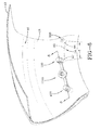
FIG. 2 is a front view of the pump and regulator assembly as shown from inside the tire ofFig. 1 . -
FIG. 3 is an exploded view of the regulator assembly. -
Fig. 4 is a section view ofFigure 2 in the direction 4-4 showing the regulator in the open position during operation. -
Fig. 5 is a section view ofFigure 2 in the direction 4-4 showing the regulator in the closed position during operation. -
FIG. 6 is a front view of a second embodiment of a regulator assembly as shown from inside the tire ofFig. 1 . -
FIG. 7 is an exploded view of the second embodiment of the regulator assembly. -
Fig. 8 is a section view ofFigure 6 in the direction 8-8 showing the regulator in the open position during operation. -
Fig. 8a is the same asFig. 8 , except that the coil spring has been replaced with a leaf spring. -
Fig. 9 is a section view ofFigure 6 in the direction 8-8 showing the regulator in the closed position during operation. -
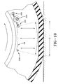
Fig. 10 is a view from inside the tire during operation. -
Fig. 11 is an exploded view of a pump outlet valve. -
Fig 12a is a cross-sectional view of the pump outlet valve in the closed position. -
Fig 12b is a cross-sectional view of the pump outlet valve during the cracking open position. -
Fig 12c is a cross-sectional view of the pump outlet valve in the open position. -
Fig. 13 is a cross-sectional view of the lower tire sidewall. -
Fig. 14 is a front view of the regulator and pump assembly illustrating a pump length of about 170 degrees. -
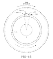
Fig. 15 is a front view of the regulator and pump assembly illustrating a pump length of about 350 degrees. - Referring to
FIG. 1 and2 , atire assembly 10 includes atire 12, apump assembly 14, and optionally atire rim 16. The tire and rim enclose atire cavity 40. As shown inFIGS. 1-2 , thepump assembly 14 is preferably mounted into thesidewall area 15 of the tire, preferably near the bead region. - The
pump assembly 14 includes anair passageway 43 which may be molded into the sidewall of the tire during vulcanization or formed post cure. When the air passageway is molded into the tire sidewall as shown inFigure 2 , the air passageway has an arc length L as measured by an angle Ψ that is measured from the center of rotation of the tire. In a first embodiment, the angle Ψ may range, and is preferably in the range of about 15-50 degrees or optionally, an angular length sufficient to extend the length of the tire footprint Z, as shown inFig. 10 . The air passageway has an arc length L that may extend in a circumferential direction, or any direction. The arc length L may range, and is preferably about the length of the tire footprint Z, as shown inFig 10 . The length is typically about 20-40 degrees when the shorter length is used. Alternatively, the pump tube length may be any desired length, typically 20 degrees or more. Thepump air passageway 43 comprises a tube body formed of a resilient, flexible material such as plastic, elastomer or rubber compounds, and is capable of withstanding repeated deformation cycles when the tube is deformed into a flattened condition subject to external force and, upon removal of such force, returns to an original condition generally circular in cross-section. The tube is of a diameter sufficient to operatively pass a volume of air sufficient for the purposes described herein and allowing a positioning of the tube in an operable location within the tire assembly as will be described. Preferably, the tube has a circular cross-sectional shape, although other shapes such as elliptical may be utilized. The tube may be a discrete tube that is inserted into the tire during tire manufacturing, or the tube may be molded into shape by the presence of a removable strip that forms the passageway when removed. - As shown in
Figure 2 , thepump passageway 43 has aninlet end 42 connected to aninlet fitting 100, and anoutlet end 44 that is connected to anoutlet valve 200. Theinlet fitting 100 is in fluid communication with ainlet control valve 300. Theinlet control valve 300 is in fluid communication with aninlet filter assembly 450. - A first embodiment of an
inlet control valve 300 is shown inFigures 2-5 . Theinlet control valve 300 functions to regulate the flow of air to thepump 14. Theinlet control valve 300 has acentral housing 310 that houses aninterior chamber 320. Theinterior chamber 320 has acentral opening 312. Opposite thecentral opening 312 is anoutlet port 330. The outlet port is raised from thebottom surface 313 and extends into the interior of thechamber 320. The outlet port is positioned to engage apressure membrane 550. - The pressure membrane has an
upper surface 551 that is substantially planar. The pressure membrane has alower surface 553 wherein aplug 555 extends from the lower surface. The pressure membrane further has anannular sidewall 556 which extends downwardly from the upper surface, forming alip 557. Thelip 557 is preferably annular, and snaps in anannular cutout 559 formed on theouter housing 310. The pressure membrane is a disk shaped member made of a flexible material such as, but not limited to, rubber, elastomer, plastic or silicone. Theouter surface 551 of the pressure membrane is in fluid communication with the pressure of thetire chamber 40. Thelower surface 553 of the pressure membrane is in fluid communication with theinterior chamber 320. Theplug 555 is positioned to close theoutlet port 330. Aspring 580 is positioned in theinterior chamber 320 to bias thepressure membrane 550 in the open position. The spring has afirst end 582 that is received about theplug 555. The spring has asecond end 584 that is wrapped around the outer surface of theoutlet port 330. Afirst washer 586 may be received between the springfirst end 582 and thepressure membrane 550. Asecond washer 588 may be received between the springsecond end 584 and the bottom of thechamber 313. Thus the balance of pressure forces on each side of the pressure membrane actuates thepressure membrane plug 555 to open and close theoutlet port 330. Amembrane support member 590 is received over thepressure membrane 550. Themembrane support member 590 has a plurality ofholes 592 in theouter surface 591 of the lid, to allow the pressure membrane to be in fluid communication with thetire cavity 40. Themembrane support member 590 is formed of a rigid material, and the support member allows a preloading of the spring via the pressure membrane. - Extending from the
central housing 310 is a first and secondflexible duct central housing 310. Eachflexible duct central housing 310. Eachflexible duct internal passageway - The
internal passageway 404 of the firstflexible duct 400 has afirst opening 402 that is located inside theinterior chamber 320. Theinternal passageway 404 of the firstflexible duct 400 has asecond end 406 that is in fluid communication with aninlet filter assembly 450. Theinlet device 450 supplies outside filtered air to the regulator via the firstflexible duct 400, and is described in more detail below. - The
internal passageway 504 of the secondflexible duct 500 is shown integrally formed with theoutlet port 330 of theinterior chamber 320. Theinternal passageway 504 has asecond end 506 in fluid communication with aninlet fitting 100. The inlet fitting 100 may be a hollow screw such as a banjo screw. The inlet fitting 100 has aninternal passageway 102 withinlet holes 104 that communicate flow to theinlet 42 of thepump passageway 43. The inlet fitting 100 may comprise a screw with an internal passageway, and has an outer threaded surface 106 that is received in asleeve 110. Thesleeve 110 has a bore that extends completely therethrough. The sleeve is mounted in the tire. - A second embodiment of the
inlet control valve 1100 is shown inFigures 6-9 . Theinlet control valve 1100 is the same as 300 except for the following differences. Themembrane 1102 does not have aplug 555 on the lower surface. The membrane has a non-planar upper surface with a recessedinterior portion 1104. The recessed interior portion extends into the interior of the interior chamber and is positioned to open and close theoutlet passageway 330. Acoil spring 580 is positioned to bias the pressure membrane in the open position. Thecoil spring 580 may be replaced with aleaf spring 583 as shown inFigure 8A . - The
inlet filter assembly 450 is shown inFigure 4 . Theinlet filter assembly 450 includes aninsert sleeve 452 that is hollow and has an internal threadedbore 454. Theinsert sleeve 452 is inserted into the tire, typically in thesidewall 15. Theinsert sleeve 452 may be inserted into the tire post cure or may be molded into the tire as shown inFigure 2 . Anair passage screw 460 has an outer threadedbody 463 that is screwed into the internal threaded bore 454 of the insert sleeve. Theair passage screw 460 has aninternal passageway 462 having anopening 464. Afilter 470 is inserted throughopening 464 and is received in theinternal passageway 462. Afilter cap 480 has a threadedend 482 that is received in theopening 464 of theair passage screw 460. The filter cap is positioned on the outside surface of the tire, typically on the tire sidewall as shown inFigure 1 . The filter cap has a plurality ofholes 484 for allowing the flow of air into theinlet filter 470. Outside air entershole 484 and then through the filter cap into and throughfilter 470. The filter air exits thefilter 470 into theinternal passageway 462 of theair passage screw 460. The air exits theinternal passageway 462 throughexit hole 490 and then into theinlet end 406 of the firstflexible duct 400. The inlet end of theflexible duct 400 has acircular flange 495 surrounding ahole 410 through which the air passage screw is inserted. Theexit hole 490 is located in acircumferential groove 491 to facilitate fluid communication withinlet hole 406 of the firstflexible duct 400. Thecircular flange 495 functions like a sealing gasket if it is made of a flexible soft material like rubber. - As described above, a
first end 42 of the pump is connected to a regulator and a check valve. Thesecond end 44 of the pump is connected to apump outlet valve 200. The pump outlet valve is shown inFigures 11 ,12A-C . Thepump outlet valve 200 includes aninsert sleeve 202 that is inserted into the tire on an interior surface, typically the inner sidewall as shown inFigure 2 . Theinsert sleeve 202 has an internal threadedbore 204. Theinsert sleeve 202 may be molded into thetire 12 or inserted post cure. The insert is installed in the tire area so that theinternal bore 204 is in fluid communication with thepump outlet end 44. Avalve body 210 has an outer threadedsurface 212 that is received withininsert 202. Thevalve body 210 has acentral passage 215 that has afirst opening 218 that is in fluid communication with the insert sleeve bore 204 and thepump passageway 43outlet end 44 when inserted into the tire. Thecentral passage 215 has anoutlet end 217 that is in fluid communication with the tire cavity. The valve body has a shapedhead 222 such as a hexagonal shaped head bore 223 for receiving a mating tool such as an alien wrench useful for tightening thevalve body 210 inside thesleeve 202. Thecentral passage 215 further includes aretainer slot 230 for receivingflexible stopper 240. Theflexible stopper 240 is preferably made of a resilient material such as rubber, silicone, or an elastomer. Theflexible stopper 240 has a disk shapedlower end 242, and twoopposed legs 244 which extend from thelower end 242. Eachleg 244 has ashoe 250 which has a curved enlarged shape and is made of a resilient material. As shown, the shoe is a semi-circle, although other shapes would work for the invention. Although theflexible stopper 240 is shown with twolegs 244, the stopper could have asingle leg 244 with a shoe thereon, and the shoe could be annular with holes that allow passage of air therethrough. - The flexible stopper is mounted inside the central passage so that each
shoe 250 of the flexible stopper is received in theannular retainer slot 230, and the disklower end 242 is positioned to open and close thepump end 44. -
Figures 12A-C illustrate thepump outlet valve 200 installed and operational.Figure 12C illustrates flow from thepump outlet 44 to thepump outlet valve 200. The disklower end 242 of theflexible stopper 240 does not seal thepump outlet 44 when the flow direction is towards thepump outlet valve 200. The flow travels through thecentral passage 215, around and through thelegs 244 and exits thepassage outlet 217 to the tire cavity.Figure 12A illustrates the disk lower end 142 of the flexible stopper 140 sealing thepump end 44 so that flow is blocked from flowing to thetire cavity 40.Figure 12B illustrates the disk lower end 142 of the flexible stopper 140 being lifted by the valve cracking pressure when the pump starts pumping. - An additional check valve like the
check valve 200 may be optionally used between thepump inlet passageway 42 and the outlet of the regulator. - As will be appreciated from
FIG. 2 , theinlet control valve 300 is in fluid communication with the inlet end of thepump passageway 43. As shown inFigure 10 , as the tire rotates, a footprint is formed against the ground surface. A compressive force F is directed into the tire from the footprint and acts to flatten thepump passageway 43. Flattening of thepump passageway 43 forces the compressed air towards thepump outlet device 200. Due to the increase in pressure at thepump outlet 44, the pressure unseats thedisk 242 from the opening of thepump outlet 44, which allows the pumped air to exit the pump outlet device throughpassage 215 into thetire cavity 40, as shown inFig. 12C . - The
inlet control valve 300 controls the flow of outside air into the pump. If the tire pressure is low, themembrane 550 in theinlet control valve 300 is responsive to the tire pressure in thetire cavity 40. If the tire cavity pressure falls below a preset threshold value, the plug of the membrane will unseat from thecentral outlet port 330. Outside air will enter thefilter assembly 450, exit through the filter and enter the firstflexible duct 400, as shown inFigs. 4 and8 . The flow then exits the first flexible duct and enters the chamber and then into the second flexible duct, through the inlet fitting 100 and then into the pump inlet. The flow is then compressed through the pump and then exits the pump outlet valve into the tire cavity. The pump will pump air with each tire rotation. Thepump passageway 43 fills with air when the pump system is not in the footprint. If the tire pressure is sufficient, the inlet control valve will block flow from exiting the inlet control valve, as shown inFigs. 5 and9 . The pressure membrane is responsive to the cavity tire pressure and engages thecentral port 330 forming a seal which prevents air flow from passing through the inlet control valve. The pressure membrane material properties are adjusted to have the desired tire pressure settings. - The location of the pump assembly in the tire will be understood from
FIGS. 1 and13 . In one embodiment, thepump assembly 14 is positioned in the tire sidewall, radially outward of the rim flange surface in thechafer 600. So positioned, theair passageway 43 is radially inward from the tire footprint and is thus positioned to be flattened by forces directed from the tire footprint as described above. Although the positioning of theair passageway 43 is specifically shown in achafer 600 of the tire near the bead region, it is not limited to same, and may be located at any region of the tire that undergoes cyclical compression. The cross-sectional shape of theair passageway 43 may be elliptical or round. - As described above, the length L of the pump passageway may be about the size of the tire's footprint length Z. However, the invention is not limited to same, and may be shorter or longer as desired. See
Figure 14 which illustrates an approximate 170 degree length,Figure 15 which illustrates an approximate 340 degree length. As the length of the pump increases, the pump passageway will need to substantially open and close like a peristaltic pump. - The
pump assembly 14 may also be used with a secondary tire pressure monitoring system (TPMS) (not shown) of conventional configuration that serves as a system fault detector. The TPMS may be used to detect any fault in the self-inflation system of the tire assembly and alert the user of such a condition.
Claims (15)
- A self-inflating tire assembly comprising a tire (12) having
a tire cavity (40), first and second sidewalls (15) extending respectively from first and second tire bead regions to a tire tread region;
an air passageway (43) having an inlet end (42) and an outlet end (43), the air passageway being composed of or established by a flexible material operative to open and close when the tire (12) rotates, wherein the outlet end is in fluid communication with the tire cavity (40);
an inlet control valve (1100) having a regulator body having an interior chamber; and
a pressure membrane being mounted on the inlet control valve (1100) to enclose the interior chamber, wherein the pressure membrane has a first or lower surface that is positioned to open and close an outlet port mounted in the interior chamber, wherein the pressure membrane is in fluid communication with the tire cavity (40);
wherein the body of the inlet control valve (1100) has a first and second flexible duct, wherein said first and second flexible ducts each have an internal passageway, wherein the first flexible duct has a first end connected to an inlet filter assembly (450) and a second end is connected to the interior chamber of the inlet control valve (1100), wherein the second flexible duct has a first end connected to the outlet port of the inlet control valve (1100), and a second end in fluid communication with the inlet end of the air passageway (43). - The self-inflating tire assembly of claim 1 wherein the air passageway (43) is integrally formed in the sidewall (15) of the tire (12).
- The self-inflating tire assembly of claim 1 or 2 wherein a spring biases the pressure membrane in an open position.
- The self-inflating tire assembly of claim 3 wherein the spring is a leaf spring.
- The self-inflating tire assembly of at least one of the previous claims wherein the regulator body is not affixed or mounted in the tire (12).
- The self-inflating tire assembly of at least one of the previous claims wherein the inlet device comprises a filter (450)
- The self-inflating tire assembly of at least one of the previous claims, wherein the air passageway extends in at least one sidewall (15) or in a chafer of the tire (12) and has length of 10 degrees or greater than 10 degrees, or wherein the length of the air passageway (43) is about the same as the length of the tire footprint.
- The self-inflating tire assembly of claim 7, wherein the length of the air passageway (43) is in the range of from 10 to 30 degrees.
- The self-inflating tire assembly of at least one of the previous claims, wherein the air passageway (43) is substantially of elliptical in cross-section.
- The self-inflating tire assembly of at least one of the previous claims, wherein the air passageway (43) is positioned in a chafer of the tire (12) or wherein the air passageway (43) is positioned between a tire bead region and the rim tire mounting surface radially inward of the tire tread region.
- The self-inflating tire assembly of at least one of the previous claims, wherein a first check valve is located between the outlet of the air passageway (43) and the tire cavity (40).
- The self-inflating tire assembly of at least one of the previous claims, wherein a second check valve is located between the inlet of the air passageway (43) and the outlet of the regulator body, the second check valve being preferably mounted to the tire.
- The self-inflating tire assembly of at least one of the previous claims, wherein the filter assembly (450) has an insert sleeve (452) affixed to the tire sidewall (15), wherein the insert sleeve has an internally threaded bore that extends completely therethrough, wherein the internal bore has a first end in the tire cavity (40) and a second end open to the ambient air outside the tire (12), an air passage screw (460) having an internal passageway is received in the first end of the insert sleeve, and a filter is received within the internal passageway of the air passage screw (460).
- The self-inflating tire assembly of at least one of the previous claims, wherein the first check valve has an insert sleeve affixed to the tire sidewall, wherein the insert sleeve has an internally threaded bore that extends completely therethrough, wherein the internal bore has a first end open to the tire cavity, and a second end connected to the air passageway outlet end, wherein a flexible stopper is received in the internal bore.
- The self inflating tire assembly of claim 14 wherein the flexible stopper has a disk shaped lower end that is positioned to open and close the air passageway outlet end.
Applications Claiming Priority (1)
| Application Number | Priority Date | Filing Date | Title |
|---|---|---|---|
| US201361914630P | 2013-12-11 | 2013-12-11 |
Publications (3)
| Publication Number | Publication Date |
|---|---|
| EP2883719A2 true EP2883719A2 (en) | 2015-06-17 |
| EP2883719A3 EP2883719A3 (en) | 2015-07-29 |
| EP2883719B1 EP2883719B1 (en) | 2016-09-14 |
Family
ID=52021019
Family Applications (1)
| Application Number | Title | Priority Date | Filing Date |
|---|---|---|---|
| EP14196687.9A Active EP2883719B1 (en) | 2013-12-11 | 2014-12-08 | Self-inflating tire and pressure regulator |
Country Status (5)
| Country | Link |
|---|---|
| US (1) | US9539869B2 (en) |
| EP (1) | EP2883719B1 (en) |
| JP (1) | JP2015113120A (en) |
| CN (1) | CN104708996B (en) |
| BR (1) | BR102014031117A2 (en) |
Cited By (1)
| Publication number | Priority date | Publication date | Assignee | Title |
|---|---|---|---|---|
| EP2886375A3 (en) * | 2013-12-23 | 2015-08-05 | The Goodyear Tire & Rubber Company | Self inflating tire with pressure regulator |
Families Citing this family (8)
| Publication number | Priority date | Publication date | Assignee | Title |
|---|---|---|---|---|
| US9701166B2 (en) * | 2013-12-17 | 2017-07-11 | The Goodyear Tire & Rubber Company | Bi-directional self-inflating tire with pressure regulator |
| US9233582B2 (en) * | 2013-12-17 | 2016-01-12 | The Goodyear Tire & Rubber Company | Self-inflating tire with inlet control valve |
| US9783015B2 (en) | 2014-08-12 | 2017-10-10 | The Goodyear Tire & Rubber Company | Control regulator and pumping system for an air maintenance tire |
| US9744816B2 (en) | 2014-08-12 | 2017-08-29 | The Goodyear Tire & Rubber Company | Air maintenance tire |
| US10189321B2 (en) | 2016-06-20 | 2019-01-29 | The Goodyear Tire & Rubber Company | Air maintenance tire system component protector |
| WO2018075826A1 (en) * | 2016-10-19 | 2018-04-26 | Equalaire Systems, Inc. | Inflation manifold |
| US11285764B2 (en) | 2016-12-22 | 2022-03-29 | The Goodyear Tire & Rubber Company | Control valve for an air maintenance tire |
| US10807422B2 (en) | 2016-12-22 | 2020-10-20 | The Goodyear Tire & Rubber Company | Inlet control valve for an air maintenance tire |
Family Cites Families (31)
| Publication number | Priority date | Publication date | Assignee | Title |
|---|---|---|---|---|
| US638628A (en) | 1899-03-21 | 1899-12-05 | James Frederick Everett | Self-inflating tire for bicycles. |
| US1050886A (en) | 1910-02-23 | 1913-01-21 | Anson B Wetherell | Vehicle-tire. |
| US1134361A (en) | 1912-02-13 | 1915-04-06 | Anson B Wetherell | Self-filling tire. |
| US2095489A (en) | 1934-09-13 | 1937-10-12 | Cotton George Albert | Pneumatic tire |
| GB1086512A (en) | 1964-02-24 | 1967-10-11 | Ronald Leslie Sheppard | Improvements in or relating to pneumatic tyres |
| CH548499A (en) | 1971-05-22 | 1974-04-30 | Zingone Strutture Spa | INDUSTRIAL BUILDING. |
| DE2632622A1 (en) | 1975-07-25 | 1977-02-10 | Dunlop Ltd | TIRE |
| US4570691A (en) * | 1984-05-03 | 1986-02-18 | Martus Donald G | Tire pressure regulation system |
| US4651792A (en) * | 1984-07-02 | 1987-03-24 | Allen F. Ehle | Automatic tire pressurizing system |
| FR2618102B1 (en) * | 1987-07-15 | 1990-02-16 | Michelin & Cie | INFLATION OF A ROTATING TIRE |
| US20040112495A1 (en) | 2002-12-09 | 2004-06-17 | Curtis Arlen Weise | Self inflating tire |
| DE10335244A1 (en) | 2003-08-01 | 2005-03-10 | Bayerische Motoren Werke Ag | Device for air filling a rotating pneumatic tire |
| EP1604842B1 (en) | 2004-06-11 | 2013-04-03 | Volvo Car Corporation | Automatic tire pressurizing device |
| DE102005031099A1 (en) | 2005-06-27 | 2007-01-04 | Siemens Ag | Tire inflating device connected to wheel rim, comprises membrane and piston acting as air pump |
| CZ303718B6 (en) | 2006-05-23 | 2013-04-03 | Sithold S.R.O. | Retentivity component for adjusting pneumatic tyre pressure and process for producing thereof |
| US8919402B2 (en) | 2009-11-23 | 2014-12-30 | Anthony D. A. Hansen | Automatic inflator for maintaining a tire pressure |
| US8113254B2 (en) | 2009-12-21 | 2012-02-14 | The Goodyear Tire & Rubber Company | Self-inflating tire |
| US8042586B2 (en) | 2009-12-21 | 2011-10-25 | The Goodyear Tire & Rubber Company | Self-inflating tire assembly |
| US8291950B2 (en) | 2010-10-18 | 2012-10-23 | The Goodyear Tire & Rubber Company | Self-inflating tire assembly |
| US8156978B1 (en) | 2010-10-18 | 2012-04-17 | The Goodyear Tire & Rubber Company | Tire and self-inflation apparatus assembly |
| US8235081B2 (en) | 2010-11-22 | 2012-08-07 | The Goodyear Tire & Rubber Company | In-line pumping assembly for self-inflating tire |
| US8662127B2 (en) | 2010-12-22 | 2014-03-04 | The Goodyear Tire & Rubber Company | Pump and actuator assembly for a self-inflating tire |
| US8656972B2 (en) | 2011-03-23 | 2014-02-25 | The Goodyear Tire & Rubber Company | Hydraulic membrane pump assembly for air maintenance tire |
| US8651155B2 (en) | 2011-03-23 | 2014-02-18 | The Goodyear Tire & Rubber Company | Hydraulic piston pump assembly for air maintenance tire |
| US8573270B2 (en) * | 2011-08-30 | 2013-11-05 | The Goodyear Tire & Rubber Company | Self-inflating tire and pressure regulator |
| US8857484B2 (en) * | 2011-08-30 | 2014-10-14 | The Goodyear Tire & Rubber Company | Self-inflating tire |
| US8701726B2 (en) | 2011-08-30 | 2014-04-22 | The Goodyear Tire & Rubber Company | Self-inflating tire |
| US8820369B2 (en) * | 2011-11-09 | 2014-09-02 | The Goodyear Tire & Rubber Company | Self-inflating tire |
| US8746306B2 (en) | 2011-11-09 | 2014-06-10 | The Goodyear Tire & Rubber Company | Self-inflating tire |
| US8955567B2 (en) | 2011-12-21 | 2015-02-17 | Richard B. O'Planick | Air maintenance tire and integral pump assembly |
| US9308784B2 (en) | 2013-12-09 | 2016-04-12 | The Goodyear Tire & Rubber Company | Pneumatic tire comprising an air pressure regulator and pressure regulator kit |
-
2014
- 2014-11-18 US US14/546,490 patent/US9539869B2/en active Active
- 2014-12-08 EP EP14196687.9A patent/EP2883719B1/en active Active
- 2014-12-10 JP JP2014249815A patent/JP2015113120A/en active Pending
- 2014-12-11 BR BR102014031117A patent/BR102014031117A2/en not_active IP Right Cessation
- 2014-12-11 CN CN201410754740.4A patent/CN104708996B/en active Active
Non-Patent Citations (1)
| Title |
|---|
| None |
Cited By (1)
| Publication number | Priority date | Publication date | Assignee | Title |
|---|---|---|---|---|
| EP2886375A3 (en) * | 2013-12-23 | 2015-08-05 | The Goodyear Tire & Rubber Company | Self inflating tire with pressure regulator |
Also Published As
| Publication number | Publication date |
|---|---|
| US20150158353A1 (en) | 2015-06-11 |
| CN104708996B (en) | 2017-08-08 |
| BR102014031117A2 (en) | 2016-03-01 |
| CN104708996A (en) | 2015-06-17 |
| US9539869B2 (en) | 2017-01-10 |
| JP2015113120A (en) | 2015-06-22 |
| EP2883719B1 (en) | 2016-09-14 |
| EP2883719A3 (en) | 2015-07-29 |
Similar Documents
| Publication | Publication Date | Title |
|---|---|---|
| EP2883719B1 (en) | Self-inflating tire and pressure regulator | |
| EP2886374B1 (en) | Self-inflatng tire with pressure regulator | |
| EP2565061B1 (en) | Self-inflating tire and pressure regulator device | |
| EP2883717B1 (en) | Self-inflating tire and pressure regulator | |
| EP2746073B1 (en) | Compact valve system for a self-inflating tire | |
| EP2886373B1 (en) | Bi-directional self-inflating tire with pressure regulator | |
| EP2842772B1 (en) | Tire having a pump and valve assembly | |
| US9126462B2 (en) | Compact valve system for self-inflating tire | |
| EP2886372B1 (en) | Self-inflating tire with inlet control valve | |
| EP2565059A2 (en) | Pneumatic tire | |
| EP2842774B1 (en) | Tire having a pump and valve assembly | |
| EP2886375A2 (en) | Self inflating tire with pressure regulator | |
| US10017016B2 (en) | Inlet air passage screw assembly for an air maintenance tire | |
| US10023016B2 (en) | Outlet screw assembly for an air maintenance tire |
Legal Events
| Date | Code | Title | Description |
|---|---|---|---|
| PUAI | Public reference made under article 153(3) epc to a published international application that has entered the european phase |
Free format text: ORIGINAL CODE: 0009012 |
|
| 17P | Request for examination filed |
Effective date: 20141208 |
|
| AK | Designated contracting states |
Kind code of ref document: A2 Designated state(s): AL AT BE BG CH CY CZ DE DK EE ES FI FR GB GR HR HU IE IS IT LI LT LU LV MC MK MT NL NO PL PT RO RS SE SI SK SM TR |
|
| AX | Request for extension of the european patent |
Extension state: BA ME |
|
| PUAL | Search report despatched |
Free format text: ORIGINAL CODE: 0009013 |
|
| AK | Designated contracting states |
Kind code of ref document: A3 Designated state(s): AL AT BE BG CH CY CZ DE DK EE ES FI FR GB GR HR HU IE IS IT LI LT LU LV MC MK MT NL NO PL PT RO RS SE SI SK SM TR |
|
| AX | Request for extension of the european patent |
Extension state: BA ME |
|
| RIC1 | Information provided on ipc code assigned before grant |
Ipc: B60C 5/12 20060101ALI20150622BHEP Ipc: B60C 23/12 20060101AFI20150622BHEP Ipc: B60C 19/00 20060101ALI20150622BHEP |
|
| R17P | Request for examination filed (corrected) |
Effective date: 20160129 |
|
| RBV | Designated contracting states (corrected) |
Designated state(s): AL AT BE BG CH CY CZ DE DK EE ES FI FR GB GR HR HU IE IS IT LI LT LU LV MC MK MT NL NO PL PT RO RS SE SI SK SM TR |
|
| GRAP | Despatch of communication of intention to grant a patent |
Free format text: ORIGINAL CODE: EPIDOSNIGR1 |
|
| RIC1 | Information provided on ipc code assigned before grant |
Ipc: B60C 5/12 20060101ALI20160308BHEP Ipc: B60C 19/00 20060101ALI20160308BHEP Ipc: B60C 23/12 20060101AFI20160308BHEP |
|
| INTG | Intention to grant announced |
Effective date: 20160408 |
|
| GRAS | Grant fee paid |
Free format text: ORIGINAL CODE: EPIDOSNIGR3 |
|
| GRAA | (expected) grant |
Free format text: ORIGINAL CODE: 0009210 |
|
| AK | Designated contracting states |
Kind code of ref document: B1 Designated state(s): AL AT BE BG CH CY CZ DE DK EE ES FI FR GB GR HR HU IE IS IT LI LT LU LV MC MK MT NL NO PL PT RO RS SE SI SK SM TR |
|
| REG | Reference to a national code |
Ref country code: GB Ref legal event code: FG4D |
|
| REG | Reference to a national code |
Ref country code: CH Ref legal event code: EP |
|
| REG | Reference to a national code |
Ref country code: FR Ref legal event code: PLFP Year of fee payment: 3 |
|
| REG | Reference to a national code |
Ref country code: IE Ref legal event code: FG4D |
|
| REG | Reference to a national code |
Ref country code: AT Ref legal event code: REF Ref document number: 828528 Country of ref document: AT Kind code of ref document: T Effective date: 20161015 |
|
| REG | Reference to a national code |
Ref country code: DE Ref legal event code: R096 Ref document number: 602014003658 Country of ref document: DE |
|
| REG | Reference to a national code |
Ref country code: LT Ref legal event code: MG4D |
|
| REG | Reference to a national code |
Ref country code: NL Ref legal event code: MP Effective date: 20160914 |
|
| PG25 | Lapsed in a contracting state [announced via postgrant information from national office to epo] |
Ref country code: NO Free format text: LAPSE BECAUSE OF FAILURE TO SUBMIT A TRANSLATION OF THE DESCRIPTION OR TO PAY THE FEE WITHIN THE PRESCRIBED TIME-LIMIT Effective date: 20161214 Ref country code: HR Free format text: LAPSE BECAUSE OF FAILURE TO SUBMIT A TRANSLATION OF THE DESCRIPTION OR TO PAY THE FEE WITHIN THE PRESCRIBED TIME-LIMIT Effective date: 20160914 Ref country code: RS Free format text: LAPSE BECAUSE OF FAILURE TO SUBMIT A TRANSLATION OF THE DESCRIPTION OR TO PAY THE FEE WITHIN THE PRESCRIBED TIME-LIMIT Effective date: 20160914 Ref country code: FI Free format text: LAPSE BECAUSE OF FAILURE TO SUBMIT A TRANSLATION OF THE DESCRIPTION OR TO PAY THE FEE WITHIN THE PRESCRIBED TIME-LIMIT Effective date: 20160914 Ref country code: LT Free format text: LAPSE BECAUSE OF FAILURE TO SUBMIT A TRANSLATION OF THE DESCRIPTION OR TO PAY THE FEE WITHIN THE PRESCRIBED TIME-LIMIT Effective date: 20160914 |
|
| REG | Reference to a national code |
Ref country code: AT Ref legal event code: MK05 Ref document number: 828528 Country of ref document: AT Kind code of ref document: T Effective date: 20160914 |
|
| PG25 | Lapsed in a contracting state [announced via postgrant information from national office to epo] |
Ref country code: GR Free format text: LAPSE BECAUSE OF FAILURE TO SUBMIT A TRANSLATION OF THE DESCRIPTION OR TO PAY THE FEE WITHIN THE PRESCRIBED TIME-LIMIT Effective date: 20161215 Ref country code: LV Free format text: LAPSE BECAUSE OF FAILURE TO SUBMIT A TRANSLATION OF THE DESCRIPTION OR TO PAY THE FEE WITHIN THE PRESCRIBED TIME-LIMIT Effective date: 20160914 Ref country code: NL Free format text: LAPSE BECAUSE OF FAILURE TO SUBMIT A TRANSLATION OF THE DESCRIPTION OR TO PAY THE FEE WITHIN THE PRESCRIBED TIME-LIMIT Effective date: 20160914 Ref country code: SE Free format text: LAPSE BECAUSE OF FAILURE TO SUBMIT A TRANSLATION OF THE DESCRIPTION OR TO PAY THE FEE WITHIN THE PRESCRIBED TIME-LIMIT Effective date: 20160914 |
|
| PG25 | Lapsed in a contracting state [announced via postgrant information from national office to epo] |
Ref country code: RO Free format text: LAPSE BECAUSE OF FAILURE TO SUBMIT A TRANSLATION OF THE DESCRIPTION OR TO PAY THE FEE WITHIN THE PRESCRIBED TIME-LIMIT Effective date: 20160914 Ref country code: EE Free format text: LAPSE BECAUSE OF FAILURE TO SUBMIT A TRANSLATION OF THE DESCRIPTION OR TO PAY THE FEE WITHIN THE PRESCRIBED TIME-LIMIT Effective date: 20160914 |
|
| PG25 | Lapsed in a contracting state [announced via postgrant information from national office to epo] |
Ref country code: SM Free format text: LAPSE BECAUSE OF FAILURE TO SUBMIT A TRANSLATION OF THE DESCRIPTION OR TO PAY THE FEE WITHIN THE PRESCRIBED TIME-LIMIT Effective date: 20160914 Ref country code: CZ Free format text: LAPSE BECAUSE OF FAILURE TO SUBMIT A TRANSLATION OF THE DESCRIPTION OR TO PAY THE FEE WITHIN THE PRESCRIBED TIME-LIMIT Effective date: 20160914 Ref country code: IS Free format text: LAPSE BECAUSE OF FAILURE TO SUBMIT A TRANSLATION OF THE DESCRIPTION OR TO PAY THE FEE WITHIN THE PRESCRIBED TIME-LIMIT Effective date: 20170114 Ref country code: AT Free format text: LAPSE BECAUSE OF FAILURE TO SUBMIT A TRANSLATION OF THE DESCRIPTION OR TO PAY THE FEE WITHIN THE PRESCRIBED TIME-LIMIT Effective date: 20160914 Ref country code: BE Free format text: LAPSE BECAUSE OF FAILURE TO SUBMIT A TRANSLATION OF THE DESCRIPTION OR TO PAY THE FEE WITHIN THE PRESCRIBED TIME-LIMIT Effective date: 20160914 Ref country code: PL Free format text: LAPSE BECAUSE OF FAILURE TO SUBMIT A TRANSLATION OF THE DESCRIPTION OR TO PAY THE FEE WITHIN THE PRESCRIBED TIME-LIMIT Effective date: 20160914 Ref country code: BG Free format text: LAPSE BECAUSE OF FAILURE TO SUBMIT A TRANSLATION OF THE DESCRIPTION OR TO PAY THE FEE WITHIN THE PRESCRIBED TIME-LIMIT Effective date: 20161214 Ref country code: SK Free format text: LAPSE BECAUSE OF FAILURE TO SUBMIT A TRANSLATION OF THE DESCRIPTION OR TO PAY THE FEE WITHIN THE PRESCRIBED TIME-LIMIT Effective date: 20160914 Ref country code: PT Free format text: LAPSE BECAUSE OF FAILURE TO SUBMIT A TRANSLATION OF THE DESCRIPTION OR TO PAY THE FEE WITHIN THE PRESCRIBED TIME-LIMIT Effective date: 20170116 Ref country code: ES Free format text: LAPSE BECAUSE OF FAILURE TO SUBMIT A TRANSLATION OF THE DESCRIPTION OR TO PAY THE FEE WITHIN THE PRESCRIBED TIME-LIMIT Effective date: 20160914 |
|
| REG | Reference to a national code |
Ref country code: DE Ref legal event code: R097 Ref document number: 602014003658 Country of ref document: DE |
|
| PLBE | No opposition filed within time limit |
Free format text: ORIGINAL CODE: 0009261 |
|
| STAA | Information on the status of an ep patent application or granted ep patent |
Free format text: STATUS: NO OPPOSITION FILED WITHIN TIME LIMIT |
|
| PG25 | Lapsed in a contracting state [announced via postgrant information from national office to epo] |
Ref country code: DK Free format text: LAPSE BECAUSE OF FAILURE TO SUBMIT A TRANSLATION OF THE DESCRIPTION OR TO PAY THE FEE WITHIN THE PRESCRIBED TIME-LIMIT Effective date: 20160914 |
|
| 26N | No opposition filed |
Effective date: 20170615 |
|
| PG25 | Lapsed in a contracting state [announced via postgrant information from national office to epo] |
Ref country code: MC Free format text: LAPSE BECAUSE OF FAILURE TO SUBMIT A TRANSLATION OF THE DESCRIPTION OR TO PAY THE FEE WITHIN THE PRESCRIBED TIME-LIMIT Effective date: 20160914 |
|
| REG | Reference to a national code |
Ref country code: IE Ref legal event code: MM4A |
|
| PG25 | Lapsed in a contracting state [announced via postgrant information from national office to epo] |
Ref country code: LU Free format text: LAPSE BECAUSE OF NON-PAYMENT OF DUE FEES Effective date: 20161208 |
|
| REG | Reference to a national code |
Ref country code: FR Ref legal event code: PLFP Year of fee payment: 4 |
|
| PG25 | Lapsed in a contracting state [announced via postgrant information from national office to epo] |
Ref country code: SI Free format text: LAPSE BECAUSE OF FAILURE TO SUBMIT A TRANSLATION OF THE DESCRIPTION OR TO PAY THE FEE WITHIN THE PRESCRIBED TIME-LIMIT Effective date: 20160914 Ref country code: IE Free format text: LAPSE BECAUSE OF NON-PAYMENT OF DUE FEES Effective date: 20161208 |
|
| PG25 | Lapsed in a contracting state [announced via postgrant information from national office to epo] |
Ref country code: HU Free format text: LAPSE BECAUSE OF FAILURE TO SUBMIT A TRANSLATION OF THE DESCRIPTION OR TO PAY THE FEE WITHIN THE PRESCRIBED TIME-LIMIT; INVALID AB INITIO Effective date: 20141208 |
|
| PG25 | Lapsed in a contracting state [announced via postgrant information from national office to epo] |
Ref country code: CY Free format text: LAPSE BECAUSE OF FAILURE TO SUBMIT A TRANSLATION OF THE DESCRIPTION OR TO PAY THE FEE WITHIN THE PRESCRIBED TIME-LIMIT Effective date: 20160914 Ref country code: MK Free format text: LAPSE BECAUSE OF FAILURE TO SUBMIT A TRANSLATION OF THE DESCRIPTION OR TO PAY THE FEE WITHIN THE PRESCRIBED TIME-LIMIT Effective date: 20160914 |
|
| REG | Reference to a national code |
Ref country code: CH Ref legal event code: PL |
|
| PG25 | Lapsed in a contracting state [announced via postgrant information from national office to epo] |
Ref country code: MT Free format text: LAPSE BECAUSE OF NON-PAYMENT OF DUE FEES Effective date: 20161208 |
|
| PG25 | Lapsed in a contracting state [announced via postgrant information from national office to epo] |
Ref country code: TR Free format text: LAPSE BECAUSE OF FAILURE TO SUBMIT A TRANSLATION OF THE DESCRIPTION OR TO PAY THE FEE WITHIN THE PRESCRIBED TIME-LIMIT Effective date: 20160914 Ref country code: AL Free format text: LAPSE BECAUSE OF FAILURE TO SUBMIT A TRANSLATION OF THE DESCRIPTION OR TO PAY THE FEE WITHIN THE PRESCRIBED TIME-LIMIT Effective date: 20160914 |
|
| PG25 | Lapsed in a contracting state [announced via postgrant information from national office to epo] |
Ref country code: LI Free format text: LAPSE BECAUSE OF NON-PAYMENT OF DUE FEES Effective date: 20171231 Ref country code: CH Free format text: LAPSE BECAUSE OF NON-PAYMENT OF DUE FEES Effective date: 20171231 |
|
| GBPC | Gb: european patent ceased through non-payment of renewal fee |
Effective date: 20181208 |
|
| PG25 | Lapsed in a contracting state [announced via postgrant information from national office to epo] |
Ref country code: GB Free format text: LAPSE BECAUSE OF NON-PAYMENT OF DUE FEES Effective date: 20181208 |
|
| PGFP | Annual fee paid to national office [announced via postgrant information from national office to epo] |
Ref country code: DE Payment date: 20241001 Year of fee payment: 11 |
|
| PGFP | Annual fee paid to national office [announced via postgrant information from national office to epo] |
Ref country code: FR Payment date: 20241001 Year of fee payment: 11 |
|
| PGFP | Annual fee paid to national office [announced via postgrant information from national office to epo] |
Ref country code: IT Payment date: 20241112 Year of fee payment: 11 |