EP2883651A1 - method of fabricatind a steam turbine blade equipped with erosion shield with electron beam welding using a shim - Google Patents
method of fabricatind a steam turbine blade equipped with erosion shield with electron beam welding using a shim Download PDFInfo
- Publication number
- EP2883651A1 EP2883651A1 EP14192971.1A EP14192971A EP2883651A1 EP 2883651 A1 EP2883651 A1 EP 2883651A1 EP 14192971 A EP14192971 A EP 14192971A EP 2883651 A1 EP2883651 A1 EP 2883651A1
- Authority
- EP
- European Patent Office
- Prior art keywords
- steam turbine
- turbine blade
- erosion shield
- electron beam
- blade
- Prior art date
- Legal status (The legal status is an assumption and is not a legal conclusion. Google has not performed a legal analysis and makes no representation as to the accuracy of the status listed.)
- Granted
Links
Images


Classifications
-
- B—PERFORMING OPERATIONS; TRANSPORTING
- B23—MACHINE TOOLS; METAL-WORKING NOT OTHERWISE PROVIDED FOR
- B23K—SOLDERING OR UNSOLDERING; WELDING; CLADDING OR PLATING BY SOLDERING OR WELDING; CUTTING BY APPLYING HEAT LOCALLY, e.g. FLAME CUTTING; WORKING BY LASER BEAM
- B23K15/00—Electron-beam welding or cutting
- B23K15/0046—Welding
- B23K15/0053—Seam welding
- B23K15/0066—Seam welding with backing means disposed under the seams
-
- B—PERFORMING OPERATIONS; TRANSPORTING
- B23—MACHINE TOOLS; METAL-WORKING NOT OTHERWISE PROVIDED FOR
- B23K—SOLDERING OR UNSOLDERING; WELDING; CLADDING OR PLATING BY SOLDERING OR WELDING; CUTTING BY APPLYING HEAT LOCALLY, e.g. FLAME CUTTING; WORKING BY LASER BEAM
- B23K15/00—Electron-beam welding or cutting
- B23K15/0046—Welding
- B23K15/0053—Seam welding
- B23K15/0073—Seam welding with interposition of particular material to facilitate connecting the parts, e.g. using a filler
-
- B—PERFORMING OPERATIONS; TRANSPORTING
- B23—MACHINE TOOLS; METAL-WORKING NOT OTHERWISE PROVIDED FOR
- B23K—SOLDERING OR UNSOLDERING; WELDING; CLADDING OR PLATING BY SOLDERING OR WELDING; CUTTING BY APPLYING HEAT LOCALLY, e.g. FLAME CUTTING; WORKING BY LASER BEAM
- B23K15/00—Electron-beam welding or cutting
- B23K15/0046—Welding
- B23K15/0093—Welding characterised by the properties of the materials to be welded
-
- B—PERFORMING OPERATIONS; TRANSPORTING
- B23—MACHINE TOOLS; METAL-WORKING NOT OTHERWISE PROVIDED FOR
- B23K—SOLDERING OR UNSOLDERING; WELDING; CLADDING OR PLATING BY SOLDERING OR WELDING; CUTTING BY APPLYING HEAT LOCALLY, e.g. FLAME CUTTING; WORKING BY LASER BEAM
- B23K37/00—Auxiliary devices or processes, not specially adapted for a procedure covered by only one of the other main groups of this subclass
- B23K37/06—Auxiliary devices or processes, not specially adapted for a procedure covered by only one of the other main groups of this subclass for positioning the molten material, e.g. confining it to a desired area
-
- B—PERFORMING OPERATIONS; TRANSPORTING
- B23—MACHINE TOOLS; METAL-WORKING NOT OTHERWISE PROVIDED FOR
- B23P—METAL-WORKING NOT OTHERWISE PROVIDED FOR; COMBINED OPERATIONS; UNIVERSAL MACHINE TOOLS
- B23P15/00—Making specific metal objects by operations not covered by a single other subclass or a group in this subclass
- B23P15/04—Making specific metal objects by operations not covered by a single other subclass or a group in this subclass turbine or like blades from several pieces
-
- C—CHEMISTRY; METALLURGY
- C22—METALLURGY; FERROUS OR NON-FERROUS ALLOYS; TREATMENT OF ALLOYS OR NON-FERROUS METALS
- C22C—ALLOYS
- C22C14/00—Alloys based on titanium
-
- C—CHEMISTRY; METALLURGY
- C22—METALLURGY; FERROUS OR NON-FERROUS ALLOYS; TREATMENT OF ALLOYS OR NON-FERROUS METALS
- C22C—ALLOYS
- C22C38/00—Ferrous alloys, e.g. steel alloys
- C22C38/18—Ferrous alloys, e.g. steel alloys containing chromium
-
- F—MECHANICAL ENGINEERING; LIGHTING; HEATING; WEAPONS; BLASTING
- F01—MACHINES OR ENGINES IN GENERAL; ENGINE PLANTS IN GENERAL; STEAM ENGINES
- F01D—NON-POSITIVE DISPLACEMENT MACHINES OR ENGINES, e.g. STEAM TURBINES
- F01D5/00—Blades; Blade-carrying members; Heating, heat-insulating, cooling or antivibration means on the blades or the members
- F01D5/12—Blades
- F01D5/14—Form or construction
- F01D5/147—Construction, i.e. structural features, e.g. of weight-saving hollow blades
-
- F—MECHANICAL ENGINEERING; LIGHTING; HEATING; WEAPONS; BLASTING
- F01—MACHINES OR ENGINES IN GENERAL; ENGINE PLANTS IN GENERAL; STEAM ENGINES
- F01D—NON-POSITIVE DISPLACEMENT MACHINES OR ENGINES, e.g. STEAM TURBINES
- F01D5/00—Blades; Blade-carrying members; Heating, heat-insulating, cooling or antivibration means on the blades or the members
- F01D5/12—Blades
- F01D5/28—Selecting particular materials; Particular measures relating thereto; Measures against erosion or corrosion
-
- F—MECHANICAL ENGINEERING; LIGHTING; HEATING; WEAPONS; BLASTING
- F01—MACHINES OR ENGINES IN GENERAL; ENGINE PLANTS IN GENERAL; STEAM ENGINES
- F01D—NON-POSITIVE DISPLACEMENT MACHINES OR ENGINES, e.g. STEAM TURBINES
- F01D5/00—Blades; Blade-carrying members; Heating, heat-insulating, cooling or antivibration means on the blades or the members
- F01D5/12—Blades
- F01D5/28—Selecting particular materials; Particular measures relating thereto; Measures against erosion or corrosion
- F01D5/288—Protective coatings for blades
-
- B—PERFORMING OPERATIONS; TRANSPORTING
- B23—MACHINE TOOLS; METAL-WORKING NOT OTHERWISE PROVIDED FOR
- B23K—SOLDERING OR UNSOLDERING; WELDING; CLADDING OR PLATING BY SOLDERING OR WELDING; CUTTING BY APPLYING HEAT LOCALLY, e.g. FLAME CUTTING; WORKING BY LASER BEAM
- B23K2101/00—Articles made by soldering, welding or cutting
- B23K2101/001—Turbines
-
- F—MECHANICAL ENGINEERING; LIGHTING; HEATING; WEAPONS; BLASTING
- F05—INDEXING SCHEMES RELATING TO ENGINES OR PUMPS IN VARIOUS SUBCLASSES OF CLASSES F01-F04
- F05D—INDEXING SCHEME FOR ASPECTS RELATING TO NON-POSITIVE-DISPLACEMENT MACHINES OR ENGINES, GAS-TURBINES OR JET-PROPULSION PLANTS
- F05D2220/00—Application
- F05D2220/30—Application in turbines
- F05D2220/31—Application in turbines in steam turbines
-
- F—MECHANICAL ENGINEERING; LIGHTING; HEATING; WEAPONS; BLASTING
- F05—INDEXING SCHEMES RELATING TO ENGINES OR PUMPS IN VARIOUS SUBCLASSES OF CLASSES F01-F04
- F05D—INDEXING SCHEME FOR ASPECTS RELATING TO NON-POSITIVE-DISPLACEMENT MACHINES OR ENGINES, GAS-TURBINES OR JET-PROPULSION PLANTS
- F05D2230/00—Manufacture
- F05D2230/10—Manufacture by removing material
-
- F—MECHANICAL ENGINEERING; LIGHTING; HEATING; WEAPONS; BLASTING
- F05—INDEXING SCHEMES RELATING TO ENGINES OR PUMPS IN VARIOUS SUBCLASSES OF CLASSES F01-F04
- F05D—INDEXING SCHEME FOR ASPECTS RELATING TO NON-POSITIVE-DISPLACEMENT MACHINES OR ENGINES, GAS-TURBINES OR JET-PROPULSION PLANTS
- F05D2230/00—Manufacture
- F05D2230/20—Manufacture essentially without removing material
- F05D2230/23—Manufacture essentially without removing material by permanently joining parts together
- F05D2230/232—Manufacture essentially without removing material by permanently joining parts together by welding
- F05D2230/233—Electron beam welding
Definitions
- the invention relates to a fabrication method of a steam turbine blade equipped with an erosion shield, and in particular, to a method of fabricating a steam turbine blade by joining an erosion shield to a steam turbine blade by means of welding.
- an erosion protection material is jointed to the leading edge of a steam turbine blade, on a side thereof, adjacent to steam-inflow with a shim material interposed therebetween through GTAW (Gas Tungsten Arc Welding) or electron beam welding in order to prevent erosion from occurring at the leading edge of the steam turbine blade for use in wet steam, as described in Patent Literatures 1 through 3.
- GTAW Gas Tungsten Arc Welding
- electron beam welding in order to prevent erosion from occurring at the leading edge of the steam turbine blade for use in wet steam
- a welding condition such as an acceleration voltage, an electron beam current, a welding speed, a focal length, etc.
- a welding condition such as an acceleration voltage, an electron beam current, a welding speed, a focal length, etc.
- a method of fabricating a steam turbine blade equipped with an erosion shield includes the steps of preparing constituent elements including the steam turbine blade having a blade part, the erosion shield, and a shim, wherein any of the constituent elements has a backing part to serve as a backing for preventing burn through of molten metal at the time of the electron beam welding; assembling the constituent elements so that the backing part is arranged on the back side of a groove; performing electron beam welding to the leading edge part of the blade part, the erosion shield and the shim while utilizing the backing; and/or applying a machining work including removal of the backing part after the electron beam welding so as to be finished up in the final shape of the blade part as a target.
- an erosion shield can be welded to the leading edge of a steam turbine blade without separately preparing a backing material, while preventing occurrence of burn through.
- Fig. 4 is a general view of a steam turbine blade, as an example of a steam turbine blade to which each of the embodiments of the present invention is applied.
- Fig. 4 illustrates the turbine blade in the final stage of the steam turbine in the case of a low pressure turbine.
- the steam turbine blade has a blade part 1, a shroud cove 7, a coupling part 8 to be coupled with a turbine rotor, and an erosion shield 2 provided at a leading edge part of the blade part (on the steam inflow side of the steam turbine blade), on the tip side thereof.
- FIGs. 1(a) through 3 (d) to be referred to later on there is shown the blade part of the steam turbine blade, in cross section, taken on line A - A of Fig. 4 .
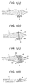
- Figs. 1 (a) through 1 (d) each illustrate a fabrication process of a steam turbine blade, according to a first embodiment of the present invention.
- a leading edge part of the tip of the steam turbine blade is shown in the respective figures.
- Constituent materials (constituent elements) that constitute the steam turbine blade are composed of the blade part 1 of the steam turbine blade, the erosion shield 2, and a shim 3 disposed between the blade part 1 and the erosion shield 2, as shown in Fig. 1 (a) .
- a Ti alloy for example, a Ti alloy containing 16% Al, and 4% V
- 12-Cr stainless steel etc.
- an erosion-resistant Ti alloy for example, a Ti alloy containing 15% Mo, 5% Zr, and 13% Al
- a Co alloy if the turbine blade is made of 12-Cr stainless steel.
- a Ti-made shim or an Ni alloy-made shim both lower in hardness than the turbine blade and the erosion shield.
- the blade part 1, the erosion shield 2, and the shim 3 are assembled, as shown in Fig. 1 (b) .
- a mechanism for prevention of burn through occurring at the time of the electron beam welding is provided in the shim 3. More specifically, a part of the shim 3 is used to serve as the mechanism for prevention of the burn through, provided on the back side of a groove, that is, on the outlet side of the electron beam.
- the shim 3 is in a sectional shape resembling the letter T as inverted.
- And tack welding 9 using GTAW is applied to respective back surfaces of the blade part 1, the erosion shield 2, and the shim 3, opposite from an incidence side of the electron beam, (on the upper side in the figure), and the blade part 1, the erosion shield 2, and the shim 3 are attached to each other in such a way as to minimize a gap therebetween so as to have no opening in the gap.
- the single-layer welding by use of the electron beam welding is applied ( Fig. 1(c) ).
- the single-layer welding is applied to the blade part 1, the erosion shield 2, and the shim 3 by use of low-voltage electron beam welding (for example, up to 60KW) using the low-voltage electron beam welding machine.
- low-voltage electron beam welding for example, up to 60KW
- occurrence of burn through at a weld metal part 4 is prevented by means of the mechanism for prevention of the burn through, composed of the part of the shim 3.
- portions of the respective constituent materials including the mechanism for prevention of the burn through, are removed by a machining work so as to be finished up in the shape of the blade part as a target ( Fig. 1 (d) ).
- a machining work removal of the mechanism for prevention of the burn through, provided in the shim 3, including removal of portions denoted by reference sign 10 shown in Fig. 1 (c) is executed.
- the removal of the portions denoted by the reference sign 10 is executed so that the blade part of the turbine blade can have the three-dimensional shape for the purpose of flow optimization.
- a finish processing is executed as appropriate after the machining work.
- a weld tip at the time of the electron beam welding are also removed.
- the weld tip is susceptible to formation of a blowhole, however, since the portions denoted by reference sign 10, including the weldtip, are removed, the soundness of a welded joint is secured.
- a backing function is imparted to a constituent material (the shim in the case of the present embodiment) by making use of the constituent material
- joining of the erosion shield to the leading edge of the steam turbine blade jointing of an erosion protection plate to the board of the blade material as a target by means of one-time welding
- the single-layer welding of the low-voltage electron beam welding without separately preparing the backing material, while preventing occurrence of the burn through. Accordingly, a cost for preparing a separate backing material is saved, and a fabrication cost can be reduced.
- the erosion shield, and the shim respectively, in particular, (at the time of an increase in the board thickness, burn through is liable to occur), the joining of the erosion shield can be easily executed. Accordingly, it is possible to fabricate a steam turbine blade designed to suit for a longer turbine blade, and a more complex three-dimensional shape by use of the electron beam welding.
- the steam turbine blade excellent in strength can be obtained owing to lack of an unwelded part. Still further, since the groove shape of the blade part 1 as well as the erosion shield 2 will be linear, it is also possible to obtain advantageous effects in that the groove shape can be easily formed.
- a second embodiment of the present invention is described below with reference to Figs. 2 (a) through 2 (d) . Description of parts in the second embodiment, identical to those in the first embodiment, is omitted.
- a part of the constituent material of a blade part 1 is used as the mechanism for prevention of burn through, provided on the back face of a groove, that is, on the outlet side of an electron beam.
- a joining area between the part of the constituent material of the blade part 1, and an erosion shield 2 is formed in a shape resembling the letter L.
- a shim 3 and the erosion shield 2 are fitted to a protrusion (pedestal) of the blade part 1, in a shape resembling the letter L.
- the protrusion in the shape resembling the letter L acts as the mechanism for prevention of the burn through.
- the present embodiment is similar to the first embodiment, and after the electron beam welding, a machining work including removal of the protrusion of the blade part 1, in the shape resembling the letter L, is executed so as to be finished up in the shape of a turbine blade as a target.
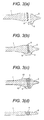
- a third embodiment of the present invention is described below with reference to Figs. 3 (a) through 3 (d) . Description of parts in the third embodiment, identical to those in the first embodiment, is omitted.
- part of the constituent material of an erosion shield 2 is used as the mechanism for prevention of burn through, provided on the back of a groove, that is, on the outlet side of an electron beam.
- a joining area between the part of the constituent material of the erosion shield 2 and a blade part 1 is formed in a shape resembling the letter L when viewed from the back side of the drawing in Figs. 3(a) and 3(b) .
- a shim 3 and the erosion shield 2 having a protrusion (pedestal) in the shape resembling the letter L are fitted to the blade part 1.
- the protrusion in the shape resembling the letter L acts as the mechanism for prevention of the burn through.
- the present embodiment is similar to the first embodiment, and after the electron beam welding, a machining work including removal of the protrusion of the erosion shield 2, in the shape resembling the letter L, is executed so as to be finished up in the shape of a turbine blade as a target.
Landscapes
- Engineering & Computer Science (AREA)
- Mechanical Engineering (AREA)
- Chemical & Material Sciences (AREA)
- Materials Engineering (AREA)
- General Engineering & Computer Science (AREA)
- Metallurgy (AREA)
- Organic Chemistry (AREA)
- Architecture (AREA)
- Physics & Mathematics (AREA)
- Optics & Photonics (AREA)
- Turbine Rotor Nozzle Sealing (AREA)
- Welding Or Cutting Using Electron Beams (AREA)
Abstract
Description
- The invention relates to a fabrication method of a steam turbine blade equipped with an erosion shield, and in particular, to a method of fabricating a steam turbine blade by joining an erosion shield to a steam turbine blade by means of welding.
- With a steam-power steam turbine or a nuclear power generation steam turbine, an erosion protection material is jointed to the leading edge of a steam turbine blade, on a side thereof, adjacent to steam-inflow with a shim material interposed therebetween through GTAW (Gas Tungsten Arc Welding) or electron beam welding in order to prevent erosion from occurring at the leading edge of the steam turbine blade for use in wet steam, as described in
Patent Literatures 1 through 3. - In general, in the case of joining executed by single-layer welding, using an electron beam, a welding condition, such as an acceleration voltage, an electron beam current, a welding speed, a focal length, etc., is finely adjusted against the type and the board thickness of a constituent material to thereby select an optimum condition for preventing occurrence of burn through before the joining is executed.
-
- [Patent Literature 1] Japanese Unexamined Patent Application Publication No.
S62(1987)-250124 - [Patent Literature 2] Japanese Unexamined Patent Application Publication No.
S63(1988)-97802 - [Patent Literature 3] Japanese Unexamined Patent Application Publication No.
Hei05(1993)-23920 - As higher efficiency of the steam turbine has been attained in recent years, there have been advances in trends toward a longer length of the blade of a turbine blade, and rendering of the turbine blade in a three-dimensional shape, for the purpose of attaining flow optimization, resulting in an increase of the board thickness of the erosion protection material. In the case where the single-layer welding by use of downward electron beam welding is applied to a blade material, an erosion protection material, and a shimmaterial, each of which is larger in thickness, metal melted by heat of the electron beam is caused to flow downward due to empty weight, concurrently with the electron beam penetrating through the board, thereby causing occurrence of burn through of molten metal. A resultant occurrence of an undercut of a bead surface will pose an important issue in the joining of the erosion protection material from a fabrication point of view.
- Further, with welding using an electron beam, the larger the thickness of a weldment as a target is, the greater will be the need for increasing a welding current value, that is, an output. Still further, with a low-voltage electron beam welding machine, there is the need for rendering a working current value larger than that for a high-voltage electron beam welding machine. As the output is increased, so does a deviation of an electron beam output, and the range of an optimum welding condition for the single-layer welding will become narrower. The deviation in a welding current will become the cause of a defect due to the burn through of the molten metal and incomplete fusion, thereby causing the joining of the erosion protection material through the single-layer welding using the electron beam welding to be extremely difficult.
- There is conceivably a method whereby a stiffening plate is placed on the back side of a groove, in a joint geometry, to thereby prevent occurrence of the burn through in order to cope with the burn through occurring at the time of application of the electron beam welding. With this method, however, there arises the need for preparing a backing material aside from those materials for use in fabrication, resulting in occurrence of a supply cost of the backing material, so that the method has demerits in terms of a fabrication cost.
- It is therefore an object of the present invention to provide a fabrication method of a steam turbine blade equipped with an erosion shield, whereby an erosion shield can be welded to the leading edge of a steam turbine blade by electron beam welding without separately preparing a backing material, while preventing occurrence of burn through.
- According to one aspect of the present invention, there is provided a method of fabricating a steam turbine blade equipped with an erosion shield. The method includes the steps of preparing constituent elements including the steam turbine blade having a blade part, the erosion shield, and a shim, wherein any of the constituent elements has a backing part to serve as a backing for preventing burn through of molten metal at the time of the electron beam welding; assembling the constituent elements so that the backing part is arranged on the back side of a groove; performing electron beam welding to the leading edge part of the blade part, the erosion shield and the shim while utilizing the backing; and/or applying a machining work including removal of the backing part after the electron beam welding so as to be finished up in the final shape of the blade part as a target.
- With the present invention, an erosion shield can be welded to the leading edge of a steam turbine blade without separately preparing a backing material, while preventing occurrence of burn through.
- Other problems, configurations, and effects of the invention will be apparent from the following detailed description of the preferred embodiments of the invention.
-
-
Figs. 1 (a) through 1 (d) each are a view illustrating the flow of a joining process for an erosion protection material, according to an embodiment of the present invention (a first embodiment); -
Figs. 2 (a) through 2 (d) each are a view illustrating the flow of a joining process for an erosion protection material, according to another embodiment of the present invention (a second embodiment); -
Figs. 3 (a) through 3 (d) each are a view illustrating the flow of a joining process for an erosion protection material, according to still another embodiment of the present invention (a third embodiment); and -
Fig. 4 is a general view of a steam turbine blade as an example of the steam turbine blade to which each embodiment of the present invention is applied. - Embodiments of the present invention are described below with reference to the accompanied drawings.
-
Fig. 4 is a general view of a steam turbine blade, as an example of a steam turbine blade to which each of the embodiments of the present invention is applied.Fig. 4 illustrates the turbine blade in the final stage of the steam turbine in the case of a low pressure turbine. The steam turbine blade has ablade part 1, a shroud cove 7, acoupling part 8 to be coupled with a turbine rotor, and anerosion shield 2 provided at a leading edge part of the blade part (on the steam inflow side of the steam turbine blade), on the tip side thereof. In each ofFigs. 1(a) through 3 (d) to be referred to later on, there is shown the blade part of the steam turbine blade, in cross section, taken on line A - A ofFig. 4 . -
Figs. 1 (a) through 1 (d) each illustrate a fabrication process of a steam turbine blade, according to a first embodiment of the present invention. A leading edge part of the tip of the steam turbine blade is shown in the respective figures. Constituent materials (constituent elements) that constitute the steam turbine blade are composed of theblade part 1 of the steam turbine blade, theerosion shield 2, and ashim 3 disposed between theblade part 1 and theerosion shield 2, as shown inFig. 1 (a) . For the turbine blade, use is made of a Ti alloy (for example, a Ti alloy containing 16% Al, and 4% V), 12-Cr stainless steel, etc. For the erosion shield, use is made of an erosion-resistant Ti alloy (for example, a Ti alloy containing 15% Mo, 5% Zr, and 13% Al) if the turbine blade is made of the Ti alloy, while use is made of a Co alloy if the turbine blade is made of 12-Cr stainless steel. For the shim, use is made of a Ti-made shim or an Ni alloy-made shim, both lower in hardness than the turbine blade and the erosion shield. - The
blade part 1, theerosion shield 2, and theshim 3 are assembled, as shown inFig. 1 (b) . With the present embodiment, a mechanism for prevention of burn through occurring at the time of the electron beam welding is provided in theshim 3. More specifically, a part of theshim 3 is used to serve as the mechanism for prevention of the burn through, provided on the back side of a groove, that is, on the outlet side of the electron beam. With the present embodiment, theshim 3 is in a sectional shape resembling the letter T as inverted. Andtack welding 9 using GTAW is applied to respective back surfaces of theblade part 1, theerosion shield 2, and theshim 3, opposite from an incidence side of the electron beam, (on the upper side in the figure), and theblade part 1, theerosion shield 2, and theshim 3 are attached to each other in such a way as to minimize a gap therebetween so as to have no opening in the gap. - Thereafter, the single-layer welding by use of the electron beam welding is applied (
Fig. 1(c) ). With the electron beam welding according to the present embodiment, the single-layer welding is applied to theblade part 1, theerosion shield 2, and theshim 3 by use of low-voltage electron beam welding (for example, up to 60KW) using the low-voltage electron beam welding machine. At this point in time, occurrence of burn through at aweld metal part 4 is prevented by means of the mechanism for prevention of the burn through, composed of the part of theshim 3. By so doing, it is possible to expand tolerance of an electron beam condition in the case of the low-voltage electron beam welding. - Subsequently, portions of the respective constituent materials, including the mechanism for prevention of the burn through, are removed by a machining work so as to be finished up in the shape of the blade part as a target (
Fig. 1 (d) ). In this machining work, removal of the mechanism for prevention of the burn through, provided in theshim 3, including removal of portions denoted byreference sign 10 shown inFig. 1 (c) is executed. The removal of the portions denoted by thereference sign 10 is executed so that the blade part of the turbine blade can have the three-dimensional shape for the purpose of flow optimization. A finish processing is executed as appropriate after the machining work. - In the machining work shown in
Fig. 1 (d) , a weld tip at the time of the electron beam welding, are also removed. The weld tip is susceptible to formation of a blowhole, however, since the portions denoted byreference sign 10, including the weldtip, are removed, the soundness of a welded joint is secured. - With the present embodiment, as a backing function is imparted to a constituent material (the shim in the case of the present embodiment) by making use of the constituent material, joining of the erosion shield to the leading edge of the steam turbine blade (joining of an erosion protection plate to the board of the blade material as a target by means of one-time welding) is enabled by the single-layer welding of the low-voltage electron beam welding without separately preparing the backing material, while preventing occurrence of the burn through. Accordingly, a cost for preparing a separate backing material is saved, and a fabrication cost can be reduced. In the case of an increase in board thickness with respect to the blade part, the erosion shield, and the shim, respectively, in particular, (at the time of an increase in the board thickness, burn through is liable to occur), the joining of the erosion shield can be easily executed. Accordingly, it is possible to fabricate a steam turbine blade designed to suit for a longer turbine blade, and a more complex three-dimensional shape by use of the electron beam welding.
- Further, with the present embodiment, the steam turbine blade excellent in strength can be obtained owing to lack of an unwelded part. Still further, since the groove shape of the
blade part 1 as well as theerosion shield 2 will be linear, it is also possible to obtain advantageous effects in that the groove shape can be easily formed. - A second embodiment of the present invention is described below with reference to
Figs. 2 (a) through 2 (d) . Description of parts in the second embodiment, identical to those in the first embodiment, is omitted. - With the present embodiment, a part of the constituent material of a
blade part 1, is used as the mechanism for prevention of burn through, provided on the back face of a groove, that is, on the outlet side of an electron beam. With the present embodiment, a joining area between the part of the constituent material of theblade part 1, and anerosion shield 2 is formed in a shape resembling the letter L. Ashim 3 and theerosion shield 2 are fitted to a protrusion (pedestal) of theblade part 1, in a shape resembling the letter L. The protrusion in the shape resembling the letter L acts as the mechanism for prevention of the burn through. Otherwise, the present embodiment is similar to the first embodiment, and after the electron beam welding, a machining work including removal of the protrusion of theblade part 1, in the shape resembling the letter L, is executed so as to be finished up in the shape of a turbine blade as a target. - With the present embodiment as well, advantageous effects basically identical to those of the first embodiment are obtained.
- A third embodiment of the present invention is described below with reference to
Figs. 3 (a) through 3 (d) . Description of parts in the third embodiment, identical to those in the first embodiment, is omitted. - With the present embodiment, part of the constituent material of an
erosion shield 2 is used as the mechanism for prevention of burn through, provided on the back of a groove, that is, on the outlet side of an electron beam. With the present embodiment, a joining area between the part of the constituent material of theerosion shield 2 and ablade part 1 is formed in a shape resembling the letter L when viewed from the back side of the drawing inFigs. 3(a) and 3(b) . Ashim 3 and theerosion shield 2 having a protrusion (pedestal) in the shape resembling the letter L are fitted to theblade part 1. The protrusion in the shape resembling the letter L acts as the mechanism for prevention of the burn through. Otherwise, the present embodiment is similar to the first embodiment, and after the electron beam welding, a machining work including removal of the protrusion of theerosion shield 2, in the shape resembling the letter L, is executed so as to be finished up in the shape of a turbine blade as a target. - With the present embodiment as well, advantageous effects basically identical to those of the first embodiment are obtained.
Claims (7)
- A method of fabricating a steam turbine blade equipped with an erosion shield, comprising the steps of:preparing constituent elements for a steam turbine blade equipped with an erosion shield (2), including the steam turbine blade having a blade part (1), the erosion shield (2) to be joined to a leading edge part of the blade part (1) on the tip side thereof, and a shim (3) to be disposed between the blade part (1) and the erosion shield (2) at the time of the electron beam welding, wherein any of the constituent elements has a backing part to serve as a backing for preventing burn through of molten metal at the time of the electron beam welding;assembling the constituent elements so that the backing part is arranged on the back side of a groove;performing electron beam welding to the leading edge part of the blade part, the erosion shield and the shim while utilizing the backing; andapplying a machining work including removal of the backing part after the electron beam welding so as to be finished up in the final shape of the blade part (1) as a target.
- The method of fabricating the steam turbine blade according to claim 1, wherein the shim (3) provided with the backing part is prepared in the step of preparing.
- The method of fabricating the steam turbine blade according to claim 2, wherein the shim (3) formed in a sectional shape resembling the letter T as inverted is prepared in the step of preparing.
- The method of fabricating the steam turbine blade according to claim 1, wherein the steam turbine blade having the blade part (1) provided with the backing part is prepared in the step of preparing.
- The method of fabricating the steam turbine blade according to claim 4, wherein the steam turbine blade having the blade part (1) formed in a sectional shape resembling the letter L at a joining area between the blade part (1) and the erosion shield (2) is prepared in the step of preparing.
- The method of fabricating the steam turbine blade according to claim 1, wherein the erosion shield (2) provided with the backing part is prepared in the step of preparing.
- The method of fabricating the steam turbine blade according to claim 6, wherein the erosion shield (2) formed in a sectional shape resembling the letter L at a joining area between the erosion shield (2) and the blade part (1) is prepared in the step of preparing.
Applications Claiming Priority (1)
| Application Number | Priority Date | Filing Date | Title |
|---|---|---|---|
| JP2013234681A JP6178703B2 (en) | 2013-11-13 | 2013-11-13 | Method for manufacturing steam turbine rotor blade with anticorrosion piece |
Publications (2)
| Publication Number | Publication Date |
|---|---|
| EP2883651A1 true EP2883651A1 (en) | 2015-06-17 |
| EP2883651B1 EP2883651B1 (en) | 2017-09-13 |
Family
ID=51982382
Family Applications (1)
| Application Number | Title | Priority Date | Filing Date |
|---|---|---|---|
| EP14192971.1A Active EP2883651B1 (en) | 2013-11-13 | 2014-11-13 | Method of fabricating a steam turbine blade equipped with erosion shield with electron beam welding using a shim |
Country Status (4)
| Country | Link |
|---|---|
| US (1) | US20160158875A1 (en) |
| EP (1) | EP2883651B1 (en) |
| JP (1) | JP6178703B2 (en) |
| CN (1) | CN104625388B (en) |
Cited By (1)
| Publication number | Priority date | Publication date | Assignee | Title |
|---|---|---|---|---|
| GB2550802B (en) * | 2015-02-17 | 2021-07-21 | Karsten Mfg Corp | Method of forming golf club head assembly |
Families Citing this family (3)
| Publication number | Priority date | Publication date | Assignee | Title |
|---|---|---|---|---|
| JP6100037B2 (en) * | 2013-03-13 | 2017-03-22 | 三菱重工業株式会社 | Steam turbine blade manufacturing method |
| US10258837B2 (en) | 2014-02-18 | 2019-04-16 | Karsten Manufacturing Corporation | Method of forming golf club head assembly |
| CN113399795A (en) * | 2021-07-14 | 2021-09-17 | 哈尔滨汽轮机厂有限责任公司 | Method for installing and welding self-shrouded diaphragm of steam turbine without installing and welding static blade grid |
Citations (7)
| Publication number | Priority date | Publication date | Assignee | Title |
|---|---|---|---|---|
| JPS5431050A (en) * | 1977-08-11 | 1979-03-07 | Toshiba Corp | Corrosion prevention shielded welding method for turbine blade |
| JPS62250124A (en) | 1986-04-23 | 1987-10-31 | Hitachi Ltd | Ti alloy turbine blade |
| JPS6397802A (en) | 1986-10-13 | 1988-04-28 | Hitachi Ltd | Ti alloy turbine blade |
| JPH0523920A (en) | 1991-07-19 | 1993-02-02 | Hitachi Ltd | Method of joining anti-corrosion piece of turbine blade |
| JPH07243302A (en) * | 1994-03-03 | 1995-09-19 | Hitachi Ltd | Welded joint of blower rotor blade with high energy beam |
| JPH09225652A (en) * | 1996-02-20 | 1997-09-02 | Hitachi Ltd | Electron beam welded joint |
| US6568077B1 (en) * | 2000-05-11 | 2003-05-27 | General Electric Company | Blisk weld repair |
Family Cites Families (9)
| Publication number | Priority date | Publication date | Assignee | Title |
|---|---|---|---|---|
| US3874736A (en) * | 1972-12-27 | 1975-04-01 | Martin Marietta Aluminum | Welded vehicle wheel and method of producing same |
| US4156123A (en) * | 1977-07-22 | 1979-05-22 | Smith International, Inc. | Method for making rock bits |
| US4818629A (en) * | 1985-08-26 | 1989-04-04 | Fansteel Inc. | Joint construction for lined equipment |
| GB8904988D0 (en) * | 1989-03-04 | 1989-04-19 | Refurbished Turbine Components | Turbine blade repair |
| JP3481501B2 (en) * | 1999-05-28 | 2003-12-22 | 株式会社日立製作所 | Structure and method of manufacturing the same |
| US6483069B2 (en) * | 2000-10-02 | 2002-11-19 | The Boeing Company | Joining of structural members by welding |
| US6596411B2 (en) * | 2001-12-06 | 2003-07-22 | General Electric Company | High energy beam welding of single-crystal superalloys and assemblies formed thereby |
| US7858897B2 (en) * | 2006-10-27 | 2010-12-28 | United Technologies Corporation | Insert weld repair |
| US7591634B2 (en) * | 2006-11-21 | 2009-09-22 | General Electric Company | Stator shim welding |
-
2013
- 2013-11-13 JP JP2013234681A patent/JP6178703B2/en active Active
-
2014
- 2014-11-12 US US14/539,591 patent/US20160158875A1/en not_active Abandoned
- 2014-11-13 EP EP14192971.1A patent/EP2883651B1/en active Active
- 2014-11-13 CN CN201410641282.3A patent/CN104625388B/en active Active
Patent Citations (7)
| Publication number | Priority date | Publication date | Assignee | Title |
|---|---|---|---|---|
| JPS5431050A (en) * | 1977-08-11 | 1979-03-07 | Toshiba Corp | Corrosion prevention shielded welding method for turbine blade |
| JPS62250124A (en) | 1986-04-23 | 1987-10-31 | Hitachi Ltd | Ti alloy turbine blade |
| JPS6397802A (en) | 1986-10-13 | 1988-04-28 | Hitachi Ltd | Ti alloy turbine blade |
| JPH0523920A (en) | 1991-07-19 | 1993-02-02 | Hitachi Ltd | Method of joining anti-corrosion piece of turbine blade |
| JPH07243302A (en) * | 1994-03-03 | 1995-09-19 | Hitachi Ltd | Welded joint of blower rotor blade with high energy beam |
| JPH09225652A (en) * | 1996-02-20 | 1997-09-02 | Hitachi Ltd | Electron beam welded joint |
| US6568077B1 (en) * | 2000-05-11 | 2003-05-27 | General Electric Company | Blisk weld repair |
Cited By (1)
| Publication number | Priority date | Publication date | Assignee | Title |
|---|---|---|---|---|
| GB2550802B (en) * | 2015-02-17 | 2021-07-21 | Karsten Mfg Corp | Method of forming golf club head assembly |
Also Published As
| Publication number | Publication date |
|---|---|
| CN104625388A (en) | 2015-05-20 |
| CN104625388B (en) | 2017-12-15 |
| US20160158875A1 (en) | 2016-06-09 |
| EP2883651B1 (en) | 2017-09-13 |
| JP6178703B2 (en) | 2017-08-09 |
| JP2015094308A (en) | 2015-05-18 |
Similar Documents
| Publication | Publication Date | Title |
|---|---|---|
| US9951632B2 (en) | Hybrid bonded turbine rotors and methods for manufacturing the same | |
| US8242406B2 (en) | Method for the manufacture of a blisk | |
| RU2649105C2 (en) | Method for friction welding a blade onto a turbine engine rotor disc and corresponding integral blade disc | |
| EP1808577B1 (en) | A welded nozzle assembly for a steam turbine | |
| US7761990B2 (en) | Method of repairing a stationary airfoil array directing three-dimensional flow | |
| EP2298489A1 (en) | Superalloy composition and method of forming a turbine engine component | |
| US20160146024A1 (en) | Hybrid bonded turbine rotors and methods for manufacturing the same | |
| EP2236762B1 (en) | Turbine Nozzle Assembly with Mechanical and Weld Fabrication | |
| US10689989B2 (en) | Method for friction-welding a blade to a turbomachine vane, including a surfacing process | |
| EP2883651B1 (en) | Method of fabricating a steam turbine blade equipped with erosion shield with electron beam welding using a shim | |
| WO2010002295A1 (en) | A welding method | |
| JP2005297066A (en) | Welding method | |
| JP2015520033A (en) | Method for forming a metal reinforcement with an insert for protecting a composite leading edge | |
| JP2014217892A (en) | Joining process, joined article, and process of fabricating joined article | |
| JP2009052559A (en) | Welding nozzle assembly for steam turbine and associated assembly fixture | |
| GB1467163A (en) | Method for joining together members of dissimilar metals | |
| US20240316643A1 (en) | Support strategy for thin-walled additive structure | |
| US9085042B2 (en) | Stud welding repair of superalloy components | |
| CA2823519C (en) | Method for repairing compressor or turbine drums | |
| EP2975225B1 (en) | Steam turbine vane manufacturing method | |
| Gerhard et al. | Manufacturing of turbine blades by shape giving CMT-Welding | |
| US8322595B2 (en) | Joining method and resultant article | |
| US12042875B2 (en) | Weld-brazing techniques | |
| US20080118768A1 (en) | Laser fillet welding | |
| US20190376396A1 (en) | Turbine blisk and process of making |
Legal Events
| Date | Code | Title | Description |
|---|---|---|---|
| PUAI | Public reference made under article 153(3) epc to a published international application that has entered the european phase |
Free format text: ORIGINAL CODE: 0009012 |
|
| 17P | Request for examination filed |
Effective date: 20141219 |
|
| AK | Designated contracting states |
Kind code of ref document: A1 Designated state(s): AL AT BE BG CH CY CZ DE DK EE ES FI FR GB GR HR HU IE IS IT LI LT LU LV MC MK MT NL NO PL PT RO RS SE SI SK SM TR |
|
| AX | Request for extension of the european patent |
Extension state: BA ME |
|
| 17Q | First examination report despatched |
Effective date: 20160519 |
|
| GRAP | Despatch of communication of intention to grant a patent |
Free format text: ORIGINAL CODE: EPIDOSNIGR1 |
|
| STAA | Information on the status of an ep patent application or granted ep patent |
Free format text: STATUS: GRANT OF PATENT IS INTENDED |
|
| INTG | Intention to grant announced |
Effective date: 20170324 |
|
| RIN1 | Information on inventor provided before grant (corrected) |
Inventor name: TANAKA, KATSUMI Inventor name: MARUYAMA, TOSHIYUKI Inventor name: ENDO, HIROYUKI Inventor name: KASHIGUCHI, KOJI Inventor name: ISHIHARA, MIKIHISA |
|
| GRAS | Grant fee paid |
Free format text: ORIGINAL CODE: EPIDOSNIGR3 |
|
| GRAA | (expected) grant |
Free format text: ORIGINAL CODE: 0009210 |
|
| STAA | Information on the status of an ep patent application or granted ep patent |
Free format text: STATUS: THE PATENT HAS BEEN GRANTED |
|
| AK | Designated contracting states |
Kind code of ref document: B1 Designated state(s): AL AT BE BG CH CY CZ DE DK EE ES FI FR GB GR HR HU IE IS IT LI LT LU LV MC MK MT NL NO PL PT RO RS SE SI SK SM TR |
|
| REG | Reference to a national code |
Ref country code: GB Ref legal event code: FG4D |
|
| REG | Reference to a national code |
Ref country code: CH Ref legal event code: EP |
|
| REG | Reference to a national code |
Ref country code: IE Ref legal event code: FG4D |
|
| REG | Reference to a national code |
Ref country code: AT Ref legal event code: REF Ref document number: 927655 Country of ref document: AT Kind code of ref document: T Effective date: 20171015 |
|
| REG | Reference to a national code |
Ref country code: DE Ref legal event code: R096 Ref document number: 602014014483 Country of ref document: DE |
|
| REG | Reference to a national code |
Ref country code: FR Ref legal event code: PLFP Year of fee payment: 4 |
|
| REG | Reference to a national code |
Ref country code: NL Ref legal event code: MP Effective date: 20170913 |
|
| REG | Reference to a national code |
Ref country code: LT Ref legal event code: MG4D |
|
| PG25 | Lapsed in a contracting state [announced via postgrant information from national office to epo] |
Ref country code: FI Free format text: LAPSE BECAUSE OF FAILURE TO SUBMIT A TRANSLATION OF THE DESCRIPTION OR TO PAY THE FEE WITHIN THE PRESCRIBED TIME-LIMIT Effective date: 20170913 Ref country code: SE Free format text: LAPSE BECAUSE OF FAILURE TO SUBMIT A TRANSLATION OF THE DESCRIPTION OR TO PAY THE FEE WITHIN THE PRESCRIBED TIME-LIMIT Effective date: 20170913 Ref country code: LT Free format text: LAPSE BECAUSE OF FAILURE TO SUBMIT A TRANSLATION OF THE DESCRIPTION OR TO PAY THE FEE WITHIN THE PRESCRIBED TIME-LIMIT Effective date: 20170913 Ref country code: NO Free format text: LAPSE BECAUSE OF FAILURE TO SUBMIT A TRANSLATION OF THE DESCRIPTION OR TO PAY THE FEE WITHIN THE PRESCRIBED TIME-LIMIT Effective date: 20171213 Ref country code: HR Free format text: LAPSE BECAUSE OF FAILURE TO SUBMIT A TRANSLATION OF THE DESCRIPTION OR TO PAY THE FEE WITHIN THE PRESCRIBED TIME-LIMIT Effective date: 20170913 |
|
| REG | Reference to a national code |
Ref country code: AT Ref legal event code: MK05 Ref document number: 927655 Country of ref document: AT Kind code of ref document: T Effective date: 20170913 |
|
| PG25 | Lapsed in a contracting state [announced via postgrant information from national office to epo] |
Ref country code: LV Free format text: LAPSE BECAUSE OF FAILURE TO SUBMIT A TRANSLATION OF THE DESCRIPTION OR TO PAY THE FEE WITHIN THE PRESCRIBED TIME-LIMIT Effective date: 20170913 Ref country code: ES Free format text: LAPSE BECAUSE OF FAILURE TO SUBMIT A TRANSLATION OF THE DESCRIPTION OR TO PAY THE FEE WITHIN THE PRESCRIBED TIME-LIMIT Effective date: 20170913 Ref country code: RS Free format text: LAPSE BECAUSE OF FAILURE TO SUBMIT A TRANSLATION OF THE DESCRIPTION OR TO PAY THE FEE WITHIN THE PRESCRIBED TIME-LIMIT Effective date: 20170913 Ref country code: BG Free format text: LAPSE BECAUSE OF FAILURE TO SUBMIT A TRANSLATION OF THE DESCRIPTION OR TO PAY THE FEE WITHIN THE PRESCRIBED TIME-LIMIT Effective date: 20171213 Ref country code: GR Free format text: LAPSE BECAUSE OF FAILURE TO SUBMIT A TRANSLATION OF THE DESCRIPTION OR TO PAY THE FEE WITHIN THE PRESCRIBED TIME-LIMIT Effective date: 20171214 |
|
| PG25 | Lapsed in a contracting state [announced via postgrant information from national office to epo] |
Ref country code: NL Free format text: LAPSE BECAUSE OF FAILURE TO SUBMIT A TRANSLATION OF THE DESCRIPTION OR TO PAY THE FEE WITHIN THE PRESCRIBED TIME-LIMIT Effective date: 20170913 |
|
| PG25 | Lapsed in a contracting state [announced via postgrant information from national office to epo] |
Ref country code: RO Free format text: LAPSE BECAUSE OF FAILURE TO SUBMIT A TRANSLATION OF THE DESCRIPTION OR TO PAY THE FEE WITHIN THE PRESCRIBED TIME-LIMIT Effective date: 20170913 Ref country code: CZ Free format text: LAPSE BECAUSE OF FAILURE TO SUBMIT A TRANSLATION OF THE DESCRIPTION OR TO PAY THE FEE WITHIN THE PRESCRIBED TIME-LIMIT Effective date: 20170913 Ref country code: PL Free format text: LAPSE BECAUSE OF FAILURE TO SUBMIT A TRANSLATION OF THE DESCRIPTION OR TO PAY THE FEE WITHIN THE PRESCRIBED TIME-LIMIT Effective date: 20170913 |
|
| PG25 | Lapsed in a contracting state [announced via postgrant information from national office to epo] |
Ref country code: EE Free format text: LAPSE BECAUSE OF FAILURE TO SUBMIT A TRANSLATION OF THE DESCRIPTION OR TO PAY THE FEE WITHIN THE PRESCRIBED TIME-LIMIT Effective date: 20170913 Ref country code: SK Free format text: LAPSE BECAUSE OF FAILURE TO SUBMIT A TRANSLATION OF THE DESCRIPTION OR TO PAY THE FEE WITHIN THE PRESCRIBED TIME-LIMIT Effective date: 20170913 Ref country code: IS Free format text: LAPSE BECAUSE OF FAILURE TO SUBMIT A TRANSLATION OF THE DESCRIPTION OR TO PAY THE FEE WITHIN THE PRESCRIBED TIME-LIMIT Effective date: 20180113 Ref country code: SM Free format text: LAPSE BECAUSE OF FAILURE TO SUBMIT A TRANSLATION OF THE DESCRIPTION OR TO PAY THE FEE WITHIN THE PRESCRIBED TIME-LIMIT Effective date: 20170913 Ref country code: AT Free format text: LAPSE BECAUSE OF FAILURE TO SUBMIT A TRANSLATION OF THE DESCRIPTION OR TO PAY THE FEE WITHIN THE PRESCRIBED TIME-LIMIT Effective date: 20170913 Ref country code: IT Free format text: LAPSE BECAUSE OF FAILURE TO SUBMIT A TRANSLATION OF THE DESCRIPTION OR TO PAY THE FEE WITHIN THE PRESCRIBED TIME-LIMIT Effective date: 20170913 |
|
| REG | Reference to a national code |
Ref country code: DE Ref legal event code: R097 Ref document number: 602014014483 Country of ref document: DE |
|
| PG25 | Lapsed in a contracting state [announced via postgrant information from national office to epo] |
Ref country code: MC Free format text: LAPSE BECAUSE OF FAILURE TO SUBMIT A TRANSLATION OF THE DESCRIPTION OR TO PAY THE FEE WITHIN THE PRESCRIBED TIME-LIMIT Effective date: 20170913 |
|
| PLBE | No opposition filed within time limit |
Free format text: ORIGINAL CODE: 0009261 |
|
| STAA | Information on the status of an ep patent application or granted ep patent |
Free format text: STATUS: NO OPPOSITION FILED WITHIN TIME LIMIT |
|
| PG25 | Lapsed in a contracting state [announced via postgrant information from national office to epo] |
Ref country code: LI Free format text: LAPSE BECAUSE OF NON-PAYMENT OF DUE FEES Effective date: 20171130 Ref country code: CH Free format text: LAPSE BECAUSE OF NON-PAYMENT OF DUE FEES Effective date: 20171130 Ref country code: DK Free format text: LAPSE BECAUSE OF FAILURE TO SUBMIT A TRANSLATION OF THE DESCRIPTION OR TO PAY THE FEE WITHIN THE PRESCRIBED TIME-LIMIT Effective date: 20170913 |
|
| 26N | No opposition filed |
Effective date: 20180614 |
|
| PG25 | Lapsed in a contracting state [announced via postgrant information from national office to epo] |
Ref country code: LU Free format text: LAPSE BECAUSE OF NON-PAYMENT OF DUE FEES Effective date: 20171113 |
|
| REG | Reference to a national code |
Ref country code: BE Ref legal event code: MM Effective date: 20171130 |
|
| REG | Reference to a national code |
Ref country code: IE Ref legal event code: MM4A |
|
| PG25 | Lapsed in a contracting state [announced via postgrant information from national office to epo] |
Ref country code: MT Free format text: LAPSE BECAUSE OF NON-PAYMENT OF DUE FEES Effective date: 20171113 |
|
| REG | Reference to a national code |
Ref country code: FR Ref legal event code: PLFP Year of fee payment: 5 |
|
| PG25 | Lapsed in a contracting state [announced via postgrant information from national office to epo] |
Ref country code: IE Free format text: LAPSE BECAUSE OF NON-PAYMENT OF DUE FEES Effective date: 20171113 |
|
| PG25 | Lapsed in a contracting state [announced via postgrant information from national office to epo] |
Ref country code: SI Free format text: LAPSE BECAUSE OF FAILURE TO SUBMIT A TRANSLATION OF THE DESCRIPTION OR TO PAY THE FEE WITHIN THE PRESCRIBED TIME-LIMIT Effective date: 20170913 Ref country code: BE Free format text: LAPSE BECAUSE OF NON-PAYMENT OF DUE FEES Effective date: 20171130 |
|
| PG25 | Lapsed in a contracting state [announced via postgrant information from national office to epo] |
Ref country code: HU Free format text: LAPSE BECAUSE OF FAILURE TO SUBMIT A TRANSLATION OF THE DESCRIPTION OR TO PAY THE FEE WITHIN THE PRESCRIBED TIME-LIMIT; INVALID AB INITIO Effective date: 20141113 |
|
| PG25 | Lapsed in a contracting state [announced via postgrant information from national office to epo] |
Ref country code: CY Free format text: LAPSE BECAUSE OF FAILURE TO SUBMIT A TRANSLATION OF THE DESCRIPTION OR TO PAY THE FEE WITHIN THE PRESCRIBED TIME-LIMIT Effective date: 20170913 |
|
| PG25 | Lapsed in a contracting state [announced via postgrant information from national office to epo] |
Ref country code: MK Free format text: LAPSE BECAUSE OF FAILURE TO SUBMIT A TRANSLATION OF THE DESCRIPTION OR TO PAY THE FEE WITHIN THE PRESCRIBED TIME-LIMIT Effective date: 20170913 |
|
| PG25 | Lapsed in a contracting state [announced via postgrant information from national office to epo] |
Ref country code: TR Free format text: LAPSE BECAUSE OF FAILURE TO SUBMIT A TRANSLATION OF THE DESCRIPTION OR TO PAY THE FEE WITHIN THE PRESCRIBED TIME-LIMIT Effective date: 20170913 |
|
| PG25 | Lapsed in a contracting state [announced via postgrant information from national office to epo] |
Ref country code: PT Free format text: LAPSE BECAUSE OF FAILURE TO SUBMIT A TRANSLATION OF THE DESCRIPTION OR TO PAY THE FEE WITHIN THE PRESCRIBED TIME-LIMIT Effective date: 20170913 |
|
| PG25 | Lapsed in a contracting state [announced via postgrant information from national office to epo] |
Ref country code: AL Free format text: LAPSE BECAUSE OF FAILURE TO SUBMIT A TRANSLATION OF THE DESCRIPTION OR TO PAY THE FEE WITHIN THE PRESCRIBED TIME-LIMIT Effective date: 20170913 |
|
| REG | Reference to a national code |
Ref country code: DE Ref legal event code: R082 Ref document number: 602014014483 Country of ref document: DE Representative=s name: MERH-IP MATIAS ERNY REICHL HOFFMANN PATENTANWA, DE Ref country code: DE Ref legal event code: R081 Ref document number: 602014014483 Country of ref document: DE Owner name: MITSUBISHI POWER, LTD., JP Free format text: FORMER OWNER: MITSUBISHI HITACHI POWER SYSTEMS, LTD., YOKOHAMA, JP |
|
| PGFP | Annual fee paid to national office [announced via postgrant information from national office to epo] |
Ref country code: FR Payment date: 20250930 Year of fee payment: 12 |
|
| PGFP | Annual fee paid to national office [announced via postgrant information from national office to epo] |
Ref country code: DE Payment date: 20250930 Year of fee payment: 12 |
|
| PGFP | Annual fee paid to national office [announced via postgrant information from national office to epo] |
Ref country code: GB Payment date: 20251001 Year of fee payment: 12 |