EP2883493A2 - Vorrichtungen und Systeme zur Echtzeit-Erkennung der Wiederherstellung der spontanen Zirkulation (ROSC) in Verfahren der Herz-Lungen-Wiederbelebung.(CPR) - Google Patents
Vorrichtungen und Systeme zur Echtzeit-Erkennung der Wiederherstellung der spontanen Zirkulation (ROSC) in Verfahren der Herz-Lungen-Wiederbelebung.(CPR) Download PDFInfo
- Publication number
- EP2883493A2 EP2883493A2 EP14181330.3A EP14181330A EP2883493A2 EP 2883493 A2 EP2883493 A2 EP 2883493A2 EP 14181330 A EP14181330 A EP 14181330A EP 2883493 A2 EP2883493 A2 EP 2883493A2
- Authority
- EP
- European Patent Office
- Prior art keywords
- rosc
- recognition
- time
- domain
- frequency
- Prior art date
- Legal status (The legal status is an assumption and is not a legal conclusion. Google has not performed a legal analysis and makes no representation as to the accuracy of the status listed.)
- Granted
Links
Images









Classifications
-
- A—HUMAN NECESSITIES
- A61—MEDICAL OR VETERINARY SCIENCE; HYGIENE
- A61B—DIAGNOSIS; SURGERY; IDENTIFICATION
- A61B5/00—Measuring for diagnostic purposes; Identification of persons
- A61B5/02—Detecting, measuring or recording for evaluating the cardiovascular system, e.g. pulse, heart rate, blood pressure or blood flow
- A61B5/024—Measuring pulse rate or heart rate
-
- A—HUMAN NECESSITIES
- A61—MEDICAL OR VETERINARY SCIENCE; HYGIENE
- A61B—DIAGNOSIS; SURGERY; IDENTIFICATION
- A61B5/00—Measuring for diagnostic purposes; Identification of persons
- A61B5/02—Detecting, measuring or recording for evaluating the cardiovascular system, e.g. pulse, heart rate, blood pressure or blood flow
- A61B5/024—Measuring pulse rate or heart rate
- A61B5/02416—Measuring pulse rate or heart rate using photoplethysmograph signals, e.g. generated by infrared radiation
-
- A—HUMAN NECESSITIES
- A61—MEDICAL OR VETERINARY SCIENCE; HYGIENE
- A61B—DIAGNOSIS; SURGERY; IDENTIFICATION
- A61B5/00—Measuring for diagnostic purposes; Identification of persons
- A61B5/02—Detecting, measuring or recording for evaluating the cardiovascular system, e.g. pulse, heart rate, blood pressure or blood flow
- A61B5/026—Measuring blood flow
-
- A—HUMAN NECESSITIES
- A61—MEDICAL OR VETERINARY SCIENCE; HYGIENE
- A61B—DIAGNOSIS; SURGERY; IDENTIFICATION
- A61B5/00—Measuring for diagnostic purposes; Identification of persons
- A61B5/145—Measuring characteristics of blood in vivo, e.g. gas concentration or pH-value ; Measuring characteristics of body fluids or tissues, e.g. interstitial fluid or cerebral tissue
- A61B5/1455—Measuring characteristics of blood in vivo, e.g. gas concentration or pH-value ; Measuring characteristics of body fluids or tissues, e.g. interstitial fluid or cerebral tissue using optical sensors, e.g. spectral photometrical oximeters
- A61B5/14551—Measuring characteristics of blood in vivo, e.g. gas concentration or pH-value ; Measuring characteristics of body fluids or tissues, e.g. interstitial fluid or cerebral tissue using optical sensors, e.g. spectral photometrical oximeters for measuring blood gases
-
- A—HUMAN NECESSITIES
- A61—MEDICAL OR VETERINARY SCIENCE; HYGIENE
- A61B—DIAGNOSIS; SURGERY; IDENTIFICATION
- A61B5/00—Measuring for diagnostic purposes; Identification of persons
- A61B5/72—Signal processing specially adapted for physiological signals or for diagnostic purposes
- A61B5/7235—Details of waveform analysis
-
- A—HUMAN NECESSITIES
- A61—MEDICAL OR VETERINARY SCIENCE; HYGIENE
- A61B—DIAGNOSIS; SURGERY; IDENTIFICATION
- A61B5/00—Measuring for diagnostic purposes; Identification of persons
- A61B5/72—Signal processing specially adapted for physiological signals or for diagnostic purposes
- A61B5/7271—Specific aspects of physiological measurement analysis
- A61B5/7282—Event detection, e.g. detecting unique waveforms indicative of a medical condition
-
- A—HUMAN NECESSITIES
- A61—MEDICAL OR VETERINARY SCIENCE; HYGIENE
- A61H—PHYSICAL THERAPY APPARATUS, e.g. DEVICES FOR LOCATING OR STIMULATING REFLEX POINTS IN THE BODY; ARTIFICIAL RESPIRATION; MASSAGE; BATHING DEVICES FOR SPECIAL THERAPEUTIC OR HYGIENIC PURPOSES OR SPECIFIC PARTS OF THE BODY
- A61H31/00—Artificial respiration by a force applied to the chest; Heart stimulation, e.g. heart massage
-
- A—HUMAN NECESSITIES
- A61—MEDICAL OR VETERINARY SCIENCE; HYGIENE
- A61H—PHYSICAL THERAPY APPARATUS, e.g. DEVICES FOR LOCATING OR STIMULATING REFLEX POINTS IN THE BODY; ARTIFICIAL RESPIRATION; MASSAGE; BATHING DEVICES FOR SPECIAL THERAPEUTIC OR HYGIENIC PURPOSES OR SPECIFIC PARTS OF THE BODY
- A61H31/00—Artificial respiration by a force applied to the chest; Heart stimulation, e.g. heart massage
- A61H31/004—Heart stimulation
- A61H31/005—Heart stimulation with feedback for the user
-
- A—HUMAN NECESSITIES
- A61—MEDICAL OR VETERINARY SCIENCE; HYGIENE
- A61B—DIAGNOSIS; SURGERY; IDENTIFICATION
- A61B2505/00—Evaluating, monitoring or diagnosing in the context of a particular type of medical care
- A61B2505/01—Emergency care
-
- A—HUMAN NECESSITIES
- A61—MEDICAL OR VETERINARY SCIENCE; HYGIENE
- A61H—PHYSICAL THERAPY APPARATUS, e.g. DEVICES FOR LOCATING OR STIMULATING REFLEX POINTS IN THE BODY; ARTIFICIAL RESPIRATION; MASSAGE; BATHING DEVICES FOR SPECIAL THERAPEUTIC OR HYGIENIC PURPOSES OR SPECIFIC PARTS OF THE BODY
- A61H2230/00—Measuring physical parameters of the user
- A61H2230/04—Heartbeat characteristics, e.g. E.G.C., blood pressure modulation
-
- A—HUMAN NECESSITIES
- A61—MEDICAL OR VETERINARY SCIENCE; HYGIENE
- A61H—PHYSICAL THERAPY APPARATUS, e.g. DEVICES FOR LOCATING OR STIMULATING REFLEX POINTS IN THE BODY; ARTIFICIAL RESPIRATION; MASSAGE; BATHING DEVICES FOR SPECIAL THERAPEUTIC OR HYGIENIC PURPOSES OR SPECIFIC PARTS OF THE BODY
- A61H2230/00—Measuring physical parameters of the user
- A61H2230/20—Blood composition characteristics
- A61H2230/207—Blood composition characteristics partial O2-value
Definitions
- This disclosure generally relates to recognition of restoration of spontaneous circulation (ROSC), and in particular relates to devices for real-time recognition of ROSC in cardio-pulmonary resuscitation (CPR) process, ROSC recognition and post-ROSC circulation quality evaluation systems, and ROSC feedback systems in CPR process.
- ROSC spontaneous circulation
- Cardiovascular disease the major manifestation of which is sudden cardiac death (SCD), has become the top cause of death.
- Cardiopulmonary resuscitation (CPR) is universally acknowledged to be the most effective method to rescue patients from cardiac arrest.
- CPR cardiovascular disease
- ROSC spontaneous circulation
- Spontaneous circulation recognition systems can be established based on the theory of pulse oximetry waveform analysis, which would make it easy to recognize ROSC during CPR. These systems may help doctors determine when to stop CPR in time and increase CPR effectiveness.
- ROSC in CPR process can be recognized based on arterial pulse oximetry technology and in combination with clinical physiological characteristics and digital signal processing methods.
- an ROSC recognition device for real-time recognition of ROSC in a CPR process can include a signal acquisition apparatus and a signal analysis apparatus.
- the signal acquisition apparatus can be used to acquire pulse oximetry waveform signals of a patient.
- the signal analysis apparatus can be used to analyze these signals to determine whether there is ROSC in the CPR process in real time.
- the signal analysis apparatus can include time-domain recognition logic and/or frequency-domain recognition logic.
- the time-domain recognition logic can determine whether there is ROSC in the CPR process by detecting envelope features of the signals in the time domain
- the frequency-domain recognition logic can determine whether there is ROSC in the CPR process by detecting time-varying features of spectral peaks of the signals in the frequency domain.
- the time-domain recognition logic can determine that there is ROSC when continuous and regular envelope features are recognized.
- the frequency-domain recognition logic can determine that there is ROSC when spectral peaks are recognized continuously at different frequencies or significant amplitude change is recognized for spectral peaks within a certain period.
- the signal acquisition apparatus may acquire the pulse oximetry waveform signals of the patient by red light and/or infrared light.
- an ROSC recognition and post-ROSC circulation quality evaluation system can include the above-described ROSC recognition device and a post-ROSC circulation quality evaluation apparatus for evaluating post-ROSC circulation quality.
- the post-ROSC circulation quality evaluation apparatus can evaluate the post-ROSC circulation quality based on variations of cardiac stroke volume within a certain period.
- the post-ROSC circulation quality evaluation apparatus can calculate area characteristics of AC components of pulse signals sampled by the ROSC recognition device to evaluate the stroke volume variations under spontaneous cardiac rhythm to reflect the post-ROSC dynamic quality.
- the post-ROSC circulation quality evaluation apparatus can evaluate the post-ROSC circulation quality based on variations of pulse rate.
- an ROSC feedback system in a CPR process can include an ROSC recognition and post-ROSC circulation quality evaluation apparatus and a cardio-pulmonary resuscitation apparatus.
- the ROSC recognition and post-ROSC circulation quality evaluation apparatus may be used for real-time recognition of ROSC in the CPR process and for post-ROSC circulation quality evaluation.
- the cardio-pulmonary resuscitation apparatus may provide compression output to a patient.
- the ROSC recognition and post-ROSC circulation quality evaluation apparatus can control the cardio-pulmonary resuscitation apparatus to stop the compression output, and can start the post-ROSC circulation quality evaluation.
- the ROSC recognition and post-ROSC circulation quality evaluation apparatus can control the cardio-pulmonary resuscitation apparatus to restart the compression output and can restart the real-time recognition of ROSC.
- the ROSC recognition and post-ROSC circulation quality evaluation apparatus can include time-domain recognition logic and/or frequency-domain recognition logic.
- the time-domain recognition logic can determine whether there is ROSC in the CPR process by detecting time envelope features of sampled signals in the time domain
- the frequency-domain recognition logic can determine whether there is ROSC in the CPR process by detecting time-varying features of spectral peaks of the sampled signals in the frequency domain.
- the time-domain recognition logic can determine that there is ROSC when continuous and regular envelope features are recognized.
- the frequency-domain recognition logic can determine that there is ROSC when spectral peaks are recognized continuously at different frequencies or significant amplitude change is recognized for spectral peaks within a certain period.
- an ROSC feedback system in a CPR process can include an ROSC recognition and post-ROSC circulation quality evaluation apparatus, a cardio-pulmonary resuscitation apparatus and a CPR quality evaluation apparatus.
- the ROSC recognition and post-ROSC circulation quality evaluation apparatus may be used for real-time recognition of ROSC in the CPR process and for post-ROSC circulation quality evaluation.
- the cardio-pulmonary resuscitation apparatus may provide compression output to a patient.
- the CPR quality evaluation apparatus may be used to evaluate CPR quality.
- the ROSC recognition and post-ROSC circulation quality evaluation apparatus can control the cardio-pulmonary resuscitation apparatus to stop the compression output, and can start the post-ROSC circulation quality evaluation.
- the ROSC recognition and post-ROSC circulation quality evaluation apparatus can control the cardio-pulmonary resuscitation apparatus to restart the compression output, and can restart the real-time recognition of ROSC. While the cardio-pulmonary resuscitation apparatus is providing the compression output, the cardio-pulmonary resuscitation apparatus can interact with the CPR quality evaluation apparatus so that the CPR quality evaluation apparatus can recognize CPR compression state and provide feedback to the cardio-pulmonary resuscitation apparatus to achieve an optimal compression output.
- the ROSC recognition and post-ROSC circulation quality evaluation apparatus can include time-domain recognition logic and/or frequency-domain recognition logic.
- the time-domain recognition logic can determine whether there is ROSC in the CPR process by detecting time envelope features of sampled signals in the time domain
- the frequency-domain recognition logic can determine whether there is ROSC in the CPR process by detecting time-varying features of spectral peaks of the sampled signals in the frequency domain.
- the time-domain recognition logic can determine that there is ROSC when continuous and regular envelope features are recognized.
- the frequency-domain recognition logic can determine that there is ROSC when spectral peaks are recognized continuously at different frequencies or significant amplitude change is recognized for spectral peaks within a certain period.
- an ROSC recognition device without external compression after defibrillation can include a signal acquisition device and a signal analysis device.
- the signal acquisition apparatus can be used to acquire pulse wave signals of a patient.
- the signal analysis apparatus can be used to analyze these signals to determine whether there is ROSC after defibrillation in real time.
- the signal acquisition apparatus can acquire the pulse wave signals of the patient by red light and/or infrared light.
- the signal analysis apparatus can perform real-time filtering on the signals by a band pass filter before analysis to eliminate noise interference beyond physiological frequency band.
- the signal analysis apparatus can establish a sliding time window for the signals, and then determine whether there is pulse feature within the sliding time window.
- the signal analysis apparatus can determine that there is the ROSC after defibrillation when: pulse wave number in the sliding time window may exceed a threshold number, and quality of a single pulse wave may exceed a threshold quality.
- the quality of the single pulse wave can be determined by its amplitude, width and shape.
- a time duration of the sliding time window can be adaptively adjusted according to frequencies of the pulse wave.
- a doctor can know whether a patient has restored his/her spontaneous circulation in compression interval or even in continuous compression process, and thus the doctor can make clinical decisions in real to avoid potential damage on the circulation system and other systems of the patient with ROSC by the external compression.
- Pulse oximetry waveform (e.g., amplitude and area under the curve) obtained in such detection may be related to hemodynamic effects such as cardiac output, volume condition and peripheral tissue perfusion. It is further discovered that the pulse oximetry waveform can reflect both cardio-pulmonary quality and ROSC characteristics in a CPR process. Therefore, some relevant parameters of the pulse oximetry waveform can be established in this disclosure by using the blood oxygen saturation detection method (e.g., near-infrared light detection), which means a continuous and non-invasive method for automatic recognition of ROSC in the CPR process can be established.
- the blood oxygen saturation detection method e.g., near-infrared light detection
- Determination of blood oxygen saturation may include two parts, namely spectrophotometric determination and blood plethysmography.
- the spectrophotometric determination can be performed by using red light with a wavelength of about 660nm and infrared light with a wavelength of about 940nm.
- Oxyhemoglobin (HbO 2 ) has less absorption for 660nm red light and more absorption for 940nm infrared light
- hemoglobin (Hb) has more absorption for 660nm red light and less absorption for 940nm infrared light.
- a ratio between the infrared light absorption intensity and the red light absorption intensity can be calculated so as to determine an oxygenation degree of hemoglobin, namely the blood oxygen saturation (SaO 2 ).
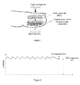
- Figure 1 is a schematic diagram for blood oxygen saturation detection.
- Two light emitting tubes that emit red light and infrared light respectively can be mounted on one side of a probe, while a photoelectric detector (i.e., receiving tube) can be mounted on the other side of the probe, where the photoelectric detector may convert detected red light and infrared light that penetrate through finger arteries into electric signals.
- Skin, muscle, fat, venous blood, pigment and bone may have constant absorption coefficients for these two lights.
- Concentrations of HbO 2 and Hb in arterial blood may have periodic changes with arteriopalmus, thereby causing periodic changes of signal intensity outputted by the photoelectric detector. Blood oxygen saturation and pulse rate can then be determined by processing these signals having periodic changes.
- blood perfusion should be provided.
- the extent of attenuation of transilluminated light energy may be related to cardiac cycle.
- peripheral blood volume is highest, and light absorption intensity reaches a maximum value, while detected light energy reaches a minimum value. The situation is reversed at the time of diastole. Variations of light absorption intensity can reflect variations of blood volume. Varying the blood volume can change the intensity of the transilluminated light energy.
- two light emitting diodes that emit about 660nm red light and about 940nm infrared light respectively may be mounted on one side, while one photoelectric detector may be mounted on an opposite side. Therefore, LEDs should be opened and closed alternatively so that the photoelectric detector can distinguish the absorption intensity under different wavelengths. Influences of ambient light on detection should be eliminated from the transilluminated light at each wavelength.
- the 660nm/940nm light penetrates through the biological tissue, there may be a difference between HbO 2 and Hb in light absorption intensity.
- Absorption at each wavelength can be a function of skin color, skin structure, iliacus muscle, blood as well as other tissues penetrated by the light.
- the light absorption intensity can be considered as a sum of pulsating absorption and non-pulsating absorption.
- Figure 2 is a schematic diagram for signals detected by the SaO 2 sensor, in which AC component can be caused by pulsating arterial blood, while DC component may be constant absorption caused by the light absorption intensities of non-pulsating arterial blood, venous blood and tissues.
- the AC component may be related to a pulsating blood volume.
- the light absorption intensity of the blood may be smallest, while the transilluminated signal may be strongest, and thus the AC signal can reach a maximum value.
- the light absorption intensity of the blood may become largest, while the transilluminated signal may be weakest, and thus the AC signal may reach a minimum value.
- the DC component is caused by non-pulsating transilluminated intensity of muscle and bone, and it represents a minimum signal value.
- a voltage range of sampled signal can be about 0-5 V, and its mapped sampled data can have a range of about 0-2097152.
- a calculated least significant bit (LSB) value can be about 2.38, namely each sampled value may correspond to 2.38 ⁇ V.
- LSB least significant bit
- the infrared light signals can first be filtered in real time by using a band pass filter of about 0.34-5.0Hz.
- a sliding time window can be established to find out whether the pulse features appear therein.
- ROSC after defibrillation can be determined when there are respectively noise line and regular pulse wave at front and back ends of the time window, pulse wave number reaches about 4-6, and a single pulse wave has relatively good quality.
- an interruption period between compressions should not exceed about 10 seconds. Therefore, such recognition can be performed precisely when there are at least about 6 pulse waves within about 10 seconds.
- a spontaneous cardiac rhythm more than about 36 times per minute can thus be accurately recognized by the method of this disclosure, where the spontaneous cardiac rhythm (time per minute) can be obtained by multiplying a frequency of spontaneous cardiac rhythm by 60.
- the pulse wave number used as a determination criterion can be adaptively set according to system features, and a time duration of the sliding time window can be adaptively adjusted according to the frequency of the pulse wave.
- Quality of the single pulse wave can be determined by its amplitude, width and shape.
- An amplitude inspection may refer to amplitude consistency (e.g., with fluctuation of less than about 10%) between a current pulse wave and at least about 3 historical pulse waves. When those pulse waves have no consistency in amplitude, the amplitude quality may be deemed to be poor.
- a width inspection may refer to width consistency (e.g, with fluctuation of less than about 10%) between the time lengths (i.e., cardiac rhythm) of the current pulse wave and the at least about 3 historical pulse waves. When those pulse waves have no consistency in width, the width quality may be deemed to be poor.
- a shape inspection may refer to a shape correlation between the shapes of the current pulse wave and the at least about 3 historical pulse waves. When the correlation is less than about 80%, the shape quality may be deemed to be poor. By considering amplitude, width and shape, the quality level of the single pulse wave can be obtained for further evaluation.
- the thresholds can be adaptively adjusted according to system features.
- the recognition of pulse wave within the sliding time window can be performed by any suitable recognition method such as difference method and inflection point method.
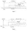
- the "defibrillation” period shows that the sampled signals have no physiological features of the pulse wave.
- the “ROSC” period shows that the patient has restored his/her spontaneous circulation with stable and regular pulse waves after a successful defibrillation.
- the "defibrillation” period shows that the sampled signals have no physiological features of the pulse wave.
- the "ROSC” period shows that the patient has restored his/her spontaneous circulation after a successful defibrillation, where the regular pulse waves grow stronger and gradually become stable.
- the manual compression may disturb the normal spontaneous circulation and the spontaneous cardiac rhythm can have gradual changes provided that the patient has relatively good cardiac functions.
- the spontaneous cardiac rhythm may be maintained at a state of less than about 60 times per minute or larger than about 120 times per minute provided that the patient has relatively poor cardiac functions. All these can provide advantageous physiological features for the ROSC recognition in the CPR process of this disclosure.
- the manual compression can form one waveform signal
- the spontaneous circulation can form another waveform signal.
- Those signals formed by the manual compression and the spontaneous circulation i.e., manual compression signal and spontaneous circulation signal
- the manual compression signal may be formed by stable compression with fixed frequency and fixed depth, such as a sine wave of about 100BPM.
- the spontaneous circulation signal may have fixed frequency, such as a sine wave of about 80BPM.
- the mixed waveform of the manual compression signal and the spontaneous circulation signal may have regular envelope.
- the regular envelope characteristic can be identified, which cannot be shown by any single-way signal. This envelope characteristic thus can provide an effective feature point for the ROSC recognition in the CPR process.
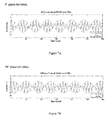
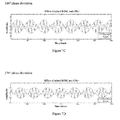
- phase deviation between the manual compression signal and the spontaneous circulation signal namely these two signals are not in 0° phase alignment with each other.
- phase deviations of 0°, 90°, 180° and 270° between the manual compression signal and the spontaneous circulation signal, which can indicate the envelope specificity of the mixed waveform.
- those fixed phase deviations may have no apparent influence on the envelope characteristic of the mixed signal. That is, the phase difference may not affect the regularity of an envelope rhythm.
- the spontaneous cardiac rhythm can have gradual changes during external compression.
- a mode can be deduced in this disclosure, where the manual compression signal can be a sine wave of fixed 100BPM, and the spontaneous cardiac rhythm signal can be a sine wave with gradual change from about 80BPM to about 120BPM.
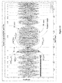
- the mixed waveform of these two signals is shown in Figure 8 .
- the mixed waveform may still have regular envelope rhythm characteristic when the spontaneous cardiac rhythm increases gradually.
- An envelope shape may depend on the spontaneous cardiac rhythm and the compression frequency. The larger the frequency deviation, the narrower the envelope width. The smaller the frequency deviation, the wider the envelope width.
- the widest envelope in Figure 8 corresponds to the situation where the spontaneous cardiac rhythm and the compression frequency are the same.
- the phase deviation between the spontaneous cardiac rhythm and the compression frequency may have no influence on the envelope rhythm characteristic.
- the physiological signals can often have the envelope characteristic during external compression. Therefore, it can be deemed that the patient has restored his/her spontaneous circulation when some continuous and regular envelope characteristics are recognized.
- the following exemplary feature recognition logic can be established based on such features.
- Peak points of each pulse wave of the physiological signals can be recognized by any suitable methods such as difference transformation method and slope transformation method. Missing parts between the peak points of the pulse waves can then be compensated by linear interpolation or curve fitting so as to maintain time synchronization with some original sampled signals and form a positive envelope curve (PE curve).
- PE curve positive envelope curve
- Valley points of each pulse wave of the physiological signals can be recognized by any suitable methods such as difference transformation method and slope transformation method. Missing parts between the valley points of the pulse waves can then be compensated by linear interpolation or curve fitting so as to maintain time synchronization with some original sampled signals and form a negative envelope curve (NE curve).
- NE curve negative envelope curve
- Figure 10 shows a flow chart for such exemplary time-domain recognition logic.
- the formed envelope may include different numbers of pulse peaks.
- the evaluation time may be inconsistent.
- ROSC can be determined and recognized within about 30s.
- Figure 11 shows some calculation parameters on a waveform.
- time-domain feature recognition logic can precisely find and recognize ROSC in the CPR process while further providing some prompt information.
- Time-domain feature recognition is well-known to present dynamic signals on a time axis, thereby having advantages of accuracy and intuition, and having relatively high correlation with the shape of the pulse wave.
- the waveform in time domain may have disorder, in which case the recognition based on the envelope feature may be affected.
- the pulse wave has some physiological echo (which is caused by ejection rebound of a blood vessel), and the envelope feature thus shows certain interfered characteristics.
- frequency domain method can convert the signals into a figure with a frequency axis as the coordinate. In this case, the signals with different frequencies can be reflected at different locations on the frequency axis directly. It can be seen that the frequency domain method may have some advantages when compared with the time domain method.
- this disclosure further describes the feature recognition of ROSC in the CPR process in terms of frequency-domain feature recognition.
- Phase deviation of time-domain waveform can be eliminated in the frequency domain due to frequency-domain characteristics.
- the spontaneous cardiac rhythm and the external compression frequency are different, two independent spectral peaks can be formed in the frequency spectrum.
- the spontaneous cardiac rhythm is a sine wave of about 80BPM and the external compression frequency is a sine wave of about 100BPM
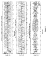
- their mixed waveform and spectral distribution can be shown as Figure 14 .
- two spectral peaks at different frequencies would be present in the frequency spectrum when the spontaneous cardiac rhythm and the external compression frequency are different.
- the spontaneous cardiac rhythm can form a spectral peak at about 1.33Hz
- the external compression can form a spectral peak at about 1.67Hz.
- the physiological signals may often include several sine waves instead of a single sine wave.
- both the external compression signals and the spontaneous cardiac rhythm signals can have harmonic spectral components.
- the spontaneous cardiac rhythm is a sine wave of about 80BPM (having first harmonic information)
- the external compression frequency is a sine wave of about 100BPM (having first harmonic information)
- their mixed waveform and spectral distribution can be shown as Figure 15 .
- a first harmonic frequency of the spontaneous cardiac rhythm can be found at about 2.67Hz, while a first harmonic frequency of the external compression frequency can be found at about 3.33Hz. It can be seen that the harmonic components would neither cause interference to the base frequency information nor have mutual interference among themselves, and the spectral peaks of the external compression and the spontaneous cardiac rhythm may still be located at different frequencies.
- the amplitude of the mixed spectral peak is a summation of the spectral peaks formed by the spontaneous cardiac rhythm and the external compression. It can be seen that the spectral amplitude can have significant changes in the case of the overlapping frequency.
- the physiological signals may often include several sine waves instead of a single sine wave. Assuming that the spontaneous cardiac rhythm is a sine wave of about 100BPM (having first harmonic information) and the external compression frequency is a sine wave of about 100BPM (having first harmonic information), their spectral distributions can be shown as Figure 17 . Theoretically speaking, the harmonic component would have no influence on the accumulation effect of the overlapping frequencies.
- the overlapping spectral peak at the base frequency still has an amplitude as a summation of the amplitudes at the base frequencies of the spontaneous cardiac rhythm and the external compression frequency
- the overlapping first harmonic spectral peak still has an amplitude as a summation of the amplitude of the first harmonic spectral peaks of the spontaneous cardiac rhythm and the external compression frequency.
- Lower spectral peaks in Figure 17 respectively stand for the base frequency information and the harmonic frequency information of the spontaneous cardiac rhythm of about 80BPM and the external compression frequency of about 100BPM. Those lower spectral peaks may function as the amplitude reference so as to show the amplitude accumulation effect.
- the physiological signals may exhibit apparent spectral features with the presence of spontaneous cardiac rhythm during external compression.
- two spectral peaks can be formed in the frequency spectrum; in contrast, the amplitude of the spectral peak may have significant change.
- the patient may have restored his/her spontaneous circulation function when the following situation is recognized: there continuously exist some spectral peaks at different frequencies, or, the amplitudes of certain spectral peaks may have significant changes.
- an exemplary frequency-domain recognition logic can be established as below.
- Sampled infrared light signals can be selected as original signals for the spectral analysis. Sampled red light signals or both kinds of signals can also be used for the analysis. In this disclosure, since the infrared light may have better anti-inference capability, the corresponding analysis will be carried out based on the infrared light.
- the sampled infrared light signals within certain time duration can be selected as the data to be converted for the spectral analysis. In the case where data segment is too long, there may be time delay for the feedback of physiological information. In the case where data segment is too short, the physiological information may be insufficient. Such time duration can be adaptively adjusted according to the requirements of system analysis. In combination with practical applications, the data within about 4-6 seconds may be chosen to be converted for the spectral analysis.
- the time-domain data within about 4-6 seconds may be converted into corresponding frequency-domain data.
- FFT Fast Fourier Transformation
- CZT Chirp z-transform
- SNR signal-to-noise ratio
- partial noise elimination such as baseline drift elimination, high-frequency noise elimination and catastrophe point suppression
- Filter method and/or root mean square method can be used in this disclosure for eliminating the baseline drift, the high-frequency noise and the catastrophe point.
- wavelet transform method, neural network method and adaptive comb filter method can also be used for removing the noise interference.
- a window can be increased for sidelobe suppression. For instance, a Kaiser window may be used for sidelobe suppression in this disclosure.
- the search may be carried out according to the following criterion: when the recognized spectral peak has a frequency beyond a physiological range of about 0.3-5Hz, or when the recognized spectral peak has an amplitude less than that of a maximum spectral peak by about 4%, the corresponding spectral peak will be discarded.
- the search may be carried out according to the following criterion: cancelling a corresponding harmonic spectral peak when a certain spectral peak has a harmonic component. Sidelobe peak of each spectral peak may be searched and deleted according to spectral theoretical formula.
- the determination rule can be as follows: those spectral peaks of about 110BPM ⁇ 10BPM (1.83Hz ⁇ 0.17Hz) can be deemed as the spectral peak of the external compression frequency.
- a sliding time window can be established to evaluate the changes of the frequency location fPeak Freq CPR and the amplitude value fPeak Amp CPR . It can be deemed that the spontaneous cardiac rhythm and the external compression frequency are basically consistent in the following situations: the frequency may be within the sliding time window and stable at about 110BPM+10BPM (1.83Hz ⁇ 0.17Hz), while the amplitude value fPeak Amp CPR has significant changes (e.g., at least about 20% fluctuations).
- Time duration of the sliding time window can be set according to system operation. For example, an observation time can be set to be about 6-8 seconds.
- both the spontaneous cardiac rhythm and the external compression frequency are about 110BPM (1.83Hz)
- the spontaneous cardiac rhythm may occur at about the 6 th second with increasing amplitude and become stable in amplitude from about the 11 th second.
- overlapping amplitude may appear at the spectral peak due to the same frequency.
- Figure 18 shows that the amplitude of the mixed frequency spectrum resulted by the spontaneous cardiac rhythm and the compression frequency can gradually increase and finally maintain stable.
- the spontaneous cardiac rhythm can be determined by evaluating the variation characteristic of the spectral amplitude within the sliding time window.
- the frequency location fPeak Freq CPR and the amplitude value fPeak Amp CPR can be evaluated comprehensively, so that the spectral peaks except that of the external compression may be used as the evaluation subject.
- a sliding time window can be established to observe a distribution range of the frequency spectrum variations therein in every second. Within the observation period, the frequency spectrum and the amplitude of the spontaneous cardiac rhythm can be found in the frequency spectrum continuously, while other interfering spectral peaks may not show any continuous characteristics because of random distribution of white noise. Therefore, whether there is spontaneous cardiac rhythm can be determined according to such continuously stable characteristics of the spectral peak over time.
- the time duration of the sliding time window can be adaptively adjusted according to system features.
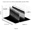
- the sliding time window may be set as about 6-8 seconds. It can be determined that the spontaneous cardiac rhythm has been restored and its frequency is inconsistent with that of the external compression in the following situations: a certain spectral peak lasting for about 6-8s can be detected, and its amplitude in the frequency spectrum per second is larger than a certain proportion of a maximum amplitude of the spectral peak of the external compression frequency. This proportion can be adjusted based on system features. A lower proportion can lead to high sensitivity but also increased risk of misrecognition. In this disclosure, a default proportion can be about 20%. As shown in Figure 19 , assuming that the spontaneous cardiac rhythm can be about 80BPM and the external compression frequency can be about 110BPM, the spontaneous cardiac rhythm can be recognized based on a continuous evaluation of the sliding time window.
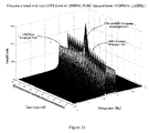
- the frequency of the spontaneous circulation can show gradually increasing tendency in the compression process. For this reason, after detecting a spectral peak lasting for about 6-8s and its amplitude can be a certain proportion (e.g., about 20% in this disclosure) of that of the external compression frequency, a monotonicity evaluation should further be carried out on the variation tendency of the location of the spectral peak. It can be deemed that the spontaneous cardiac rhythm has been restored when all the situations above are met. Assuming that the external compression frequency is about 120BPM (2.0Hz) and a pulse rate of the spontaneous cardiac rhythm increases gradually from about 70BPM to about 100BPM (1.167Hz-1.667Hz) over time, the gradually increasing effect of the spontaneous cardiac rhythm in the compression process can be found in Figure 20 .
- the spontaneous cardiac rhythm As the spontaneous cardiac rhythm increases, it may become overlapped with the external compression frequency. That is, the spontaneous cardiac rhythm and the external compression frequency may be the same at a time instant.
- the above-described feature recognition should be combined in the recognition process.
- whether there is a continuous spectral peak in about 6-8 seconds, whether its amplitude is at least a certain proportion of that of the external compression frequency, and whether this spectral peak has a monotone increasing tendency in the frequency should be evaluated.
- the amplitude variation should be evaluated for the external compression frequency.
- Figure 21 shows how the spontaneous cardiac rhythm increases gradually and overlaps with the external compression frequency, where the overlapping amplitude can be found in the case when the two frequencies are consistent.
- the time-domain logic can recognize the spontaneous cardiac rhythm during external compression from the shape feature of the mixed waveform resulted from waveform superposition.
- the frequency-domain logic can recognize the spontaneous cardiac rhythm during external compression by evaluating whether the spontaneous cardiac rhythm and the external compression frequency can overlap with each other.
- the time-domain recognition may mainly depend on the shape feature, which can be unobvious in the case of low SNR caused by motion interference or low hemoperfusion.
- the frequency-domain recognition may mainly depend on the frequency and amplitude information evaluation based on the frequency spectrum, thus exhibiting good anti-interference capability.
- ROSC may be evaluated comprehensively during external compression based on the frequency-domain analysis while combining with the time-domain analysis.
- the frequency-domain or the time-domain analysis can be used independently for ROSC recognition during external compression.
- fRatio fPeak Amp ROSC n fPeak Amp CPR n , where fRatio represents a ratio at an n th second between the amplitudes of the spectral peaks of the spontaneous cardiac rhythm and the CPR.
- a probability when the fRatio is continuously larger than or equal to 1.0 is counted in a sliding time window of about 6-8s.
- the probability is at least about 75% (which can be adaptively adjusted according to system features)
- the ROSC and even an excellent restoration condition can be determined. In this way, some technical prompt and/or warning information can be provided based on the determination results.
- the ROSC can be determined when the amplitude of the spectral peak of the external compression decreases continuously by about 25%-60% (when compared with the amplitude at an initial moment of the sliding time window) and its corresponding decreasing duration accounts for at least about 70% (which can be adaptively adjusted according to system features) of the sliding time window. In this way, some technical prompt and/or warning information can be provided based on the determination results to avoid any cardiac damage.
- the spontaneous cardiac rhythm can be restored through the CPR emergency treatment, the spontaneous circulation may be unstable and the cardiac arrest may happen again because of ischemia, hypoxia and reperfusion injury of the heart and microcirculation in the CPR process. Once failing to detect such unstable condition or cardiac arrest, an optimal rescue time may be delayed. Therefore, in order to find and warn any unstable spontaneous circulation for timely treatment, an evaluation and feedback system for circulation quality should be established after ROSC is determined.
- a practical mechanism for quality evaluation of the spontaneous cardiac rhythm can be established according to the features of the spontaneous cardiac rhythm.
- Post-ROSC circulation quality evaluation which may also be called ROSC quality for short will be described in detail hereinafter.
- the pulse waves formed by the external compression and the spontaneous circulation are basically consistent with each other, where their difference may be whether the cardiac motion is caused by manual compression or spontaneous circulation.
- a series of parameters for evaluating compression quality disclosed in a patent application CN201310474008.7 can also be used for the quality evaluation of the spontaneous circulation. This disclosure describes how to evaluate the quality of restoration of the spontaneous cardiac rhythm using PVPI parameters disclosed in the patent application CN201310474008.7 as an example.
- Original signals I can include AC components S AC and DC components S DC .
- certain factors such as body movement and background light interference may result in a drift of the DC components S DC over time, namely its numerical value may not be constant but can fluctuate with time.
- suitable technologies such as average value technology, smooth filtering technology, finite impulse response digital filter/infinite impulse response digital filter (FIR/IIR) filtering technology or curve fitting technology, the DC components S DC can be filtered out of the original signals I and the AC components S AC can be left for further data processing.
- Figure 22 shows the AC components S AC after filtering out the DC components S DC . .
- the AC components S AC may be related to blood flow, and its frequency can be consistent with the CPR compression frequency.
- the frequency of the AC components S AC can be multiplied by 60, so as to obtain the blood oxygen frequency, namely CPR compression times per minuter.
- F ROSC f S AC where F ROSC represents the CPR compression frequency, f S AC represents the frequency of the AC components S AC , and the unit of both is Hertz (Hz).
- Area characteristic of each pulse wave of the AC components S AC can be calculated to evaluate the variations of the stroke volume of the spontaneous cardiac rhythm so that the quality of restoration of the spontaneous cardiac rhythm can be reflected indirectly.
- the area value of each pulse wave can be calculated by any suitable technologies such as area integral method, which may be applicable to both continuous signals and discrete signals. In this embodiment, based on the features of fixed sampling frequency of blood oxygen technology, the method of point-by-point accumulation integral can be used to calculate the area parameter.
- S AC (n) represents the n th sampling data point of each pulse wave
- n represents the current data point of the single pulse wave
- N represents the total data length of the single pulse wave.
- Area ROSC can be a stroke volume parameter, and its unit can be defined as: PVPG (Pulse Oximeter Voltage Plethysmography), which is also called voltage volume.
- Area ROSC * can be a stroke volume parameter, and its unit can be defined as: PVPG (Pulse Oximeter Voltage Plethysmography), which is also called voltage volume
- n represents the current effective frequency component f n
- N represents the total number of the effective frequency components
- k represents the data point of the current effective frequency f n
- K represents the total data length of the effective frequency component f n .
- Area ROSC and Area ROSC * can reflect the stroke volume indirectly, which means they are not directly equal to the stroke volume. In theory, they should exhibit linear positive correlation with the cardiac ejection volume in every compression.
- drive current regulation should be performed depending on the signal conditions, so as to make the sampled blood oxygen signals fall within a measurable range.
- the variations of the drive current can lead to the changes of the AC components and the DC components by a same rate.
- the signal in solid line falls within a lower measurement range.
- drive regulation can be made so that the signals would fall within a reasonable measurement range.
- PVPG parameters i.e., Area ROSC and Area ROSC *
- Area ROSC and Area ROSC * can further be transformed as follows when referring to the changes of the corresponding DC components of the pulse wave:
- AreaIndex ROSC refers to a CPR quantization index which can be defined as voltage volume index, and its unit can be PVPI (Pulse Oximeter Voltage Amplitude Index).
- AreaIndex ROSC * refers to a CPR quantization index which can be defined as voltage volume index, and its unit can be PVPI (Pulse Oximeter Voltage Amplitude Index).
- AreaIndex ROSC and AreaIndex ROSC * can be ratios between the area value and its corresponding DC components of the single pulse wave, thus being capable of reducing the individual difference, removing the interference from drive regulation and having sound anti-interference capacity.
- AreaIndex ROSC and AreaIndex ROSC * can reflect the variation of the cardiac stroke volume. It is known from the physiological features that the stroke volume may have a minimum output. The body's peripheral blood circulation is poor in quality or even fails to meet normal physiological needs when the stroke volume is lower than its minimum output. Based on such physiological features, there may be minimum area index thresholds for the parameters AreaIndex ROSC and AreaIndex ROSC * . If these parameters are lower than those thresholds, the body may exhibit poor spontaneous cardiopulmonary quality and fail to meet the normal physiological needs. In case the stroke volume is unstable, or it gradually reduces and even stops over time, the indexes AreaIndex ROSC and AreaIndex ROSC * may have large fluctuations in their parameter values or they may decrease and even disappear over time. Based on these features, the Post-ROSC circulation quality can be recognized and evaluated effectively.
- a sliding time window may be established so that the time-varying fluctuating characteristics of the parameters AreaIndex ROSC and AreaIndex ROSC * can be evaluated in combination with a lowest physiological threshold.
- the time duration of the sliding time window can be adaptively adjusted according to system features. For example, it can be set as about 4-6 seconds.
- the spontaneous circulation under the spontaneous cardiac rhythm may be unstable when the parameters for spontaneous cardiac rhythm AreaIndex ROSC and AreaIndex ROSC * have significant fluctuations or decrease gradually.
- the unstable spontaneous circulation under the spontaneous cardiac rhythm can be determined in the following situation: the parameters in the sliding time window may decrease by about 20% relative to an average value in 30 seconds in an initial stage of the spontaneous cardiac rhythm, where the value of the parameters can be recognized on average value and standard deviation, and the fluctuating proportion can be adaptively adjusted according to system requirements; or the parameters may exhibit time-dependent decreasing tendency and have a maximum decrease by about 30% (which can be adaptively adjusted according to system requirements).
- some prompt and/or warning information can be provided so that doctors can be guided to make immediate decision to avoid further damage.
- Figure 24 is a schematic diagram for the quality evaluation of the spontaneous cardiac rhythm by using the parameter AreaIndex ROSC * as an example.
- the "unstable stage” represents that the parameters may be in a fluctuating state, where some prompt and/or warning information can be provided when the fluctuation is larger than about 20%.
- the “stable stage” represents that the parameters may be relatively stable, and prompt information can be provided to show sound cardiac rhythm of the spontaneous circulation.
- the “decreasing stage” represents that the parameters may be in a decreasing tendency, where some prompt and/or warning information can be provided when it has decreased by at least about 20%. Specifically, another prompt and/or warning information can be provided when the parameters are lower than the threshold line for a certain time.
- “Sliding window” in Figure 24 can stand for the sliding time window which can slide over time.
- the fluctuating characteristics of the parameters can be evaluated in the time window, so that the quality evaluation of the spontaneous cardiac rhythm can be analyzed, and some corresponding prompt and/or warning information can be provided.
- the pulse rate can indicate true tissue perfusion state, while the heart rate shown by ECG activity can represent the cardiac electric activity rhythm. Under the condition of sound spontaneous circulation, the pulse rate should be basically consistent with the heart rate, thereby avoiding severe fluctuations and falling within a reasonable range.
- the pulse rate decreases continuously by more than about 5%/S relative to the heart rate, becomes lower than about 60 times per minute, or seems much smaller when compared to the heart rate, the spontaneous circulation may be in an unstable state.
- ECG HR is a trend line for ECG hear rate
- pulse BPM is a trend line for ROSC pulse rate.
- a sliding time window can be established to evaluate the differences between the ECG heart rate and the ROSC pulse rate within this time window. There may be prompt/warning information when the ROSC pulse rate is detected to decrease by about 5% (which is a ratio between the ROSC pulse rate and the ECG heart rate), or when the ROSC pulse rate is detected to be lower than about 60 times per minute.
- the "stable stage” indicates consistent ECG heart rate and ROSC pulse rate
- the "decreasing-1 stage” shows the dissociation of ROSC pulse rate and ECG hear rate in which an electrical mechanical dissociation may appear
- the "decreasing-2 stage” shows that the ROSC pulse rate is continuously lower than about 60 times per minute.
- the variations of the ECG heart rate and the ROSC pulse rate can be evaluated therein.
- ROSC recognition devices for real-time recognition of ROSC in a CPR process, systems for recognition and quality evaluation of ROSC, ROSC feedback systems in a CPR process, and ROSC recognition devices without external compression after defibrillation can be provided.
- FIG 26 is a block diagram for an ROSC recognition device 100 for real-time recognition of ROSC in a CPR process according to an embodiment of this disclosure.
- the ROSC recognition device 100 may include a signal acquisition apparatus 102 and a signal analysis apparatus 104.
- the signal acquisition apparatus 102 can be used to acquire pulse oximetry waveform signals of a patient.
- the signal analysis apparatus 104 can be used to analyze these signals to determine whether there is ROSC in the CPR process.
- the signal acquisition apparatus 102 can include a receiving tube and a light-emitting tube as shown in Figure 1 . In this way, it can convert detected red light and/or infrared light penetrating through finger arteries into electrical signals so as to obtain the pulse oximetry waveform signals of the patient.
- the signal analysis apparatus 104 can include the above-described exemplary time-domain recognition logic and/or frequency-domain recognition logic.
- the time-domain recognition logic can be used to recognize whether there is ROSC in the CPR process by detecting the time-domain envelope of the sampled signals.
- the frequency-domain recognition logic can be used to recognize whether there is ROSC in the CPR process by detecting the time-varying features of the spectral peak of the sampled signals.
- ROSC can be determined when the continuous envelope feature is recognized; while for the frequency-domain recognition logic, ROSC can be determined when spectral peaks are recognized continuously at different frequencies or significant change in the amplitude of the spectral peak is recognized within a certain time.
- the signal analysis apparatus 104 can include two parts: algorithm software program, and hardware environment such as programmable logic device for the running of the algorithm software program.
- the programmable logic device may be a flash memory or a RAM.
- Other suitable programmable logic devices such as Cortex series can also be used as a carrier for the algorithm software program.
- the ROSC recognition device 100 can be a function module which may be integrated with any other auxiliary diagnostic equipment (e.g., monitoring device, defibrillator, AED, automatic resuscitator equipment and electrocardiograph) as a plug-in unit.
- auxiliary diagnostic equipment e.g., monitoring device, defibrillator, AED, automatic resuscitator equipment and electrocardiograph
- the ROSC recognition device 100 can be one-parameter medical equipments for the recognition of the spontaneous cardiac rhythm during the external compression.
- the one-parameter medical equipment can have the shape factor shown in Figure 27 .
- FIG 28 is a schematic diagram for exemplary hardware of the ROSC recognition device shown in Figure 26 .
- the ROSC recognition device may include a main control panel, an ROSC recognition sub-board, a display (e.g., an LCD screen), a loudspeaker, a battery, a charger and an indicator lamp.
- the main control panel may include two parts: system control part and power control part.
- the ROSC recognition sub-board may function as a source of all the system parameters. It can acquire physiological signals, perform calculations on the physiological signals, output some related parameters and have communication interface with a control system.
- FIG. 29 is a schematic circuit diagram for the above-described ROSC recognition sub-board.
- the ROSC recognition sub-board may include an micro-programmed Control Unit (MCU) chip, a watchdog circuit, a communication interface, an I/V conversion circuit, a gain control circuit, a bias zoom circuit, a sensor drive circuit and sensors.
- the MCU chip can include ROSC recognition algorithms and peripheral control logics.
- FIG 30 is a block diagram for an ROSC recognition and post-ROSC circulation quality evaluation system 200 according to an embodiment of this disclosure.
- This system 200 may include the ROSC recognition device 100 shown in Figure 26 and an Post-ROSC circulation quality evaluation apparatus 202 for quality evaluation of ROSC.
- the Post-ROSC circulation quality evaluation apparatus 202 may be used to evaluate the Post-ROSC circulation quality based on the variations of the cardiac stroke volume within a certain period. After ROSC is determined by the ROSC recognition device, the Post-ROSC circulation quality evaluation apparatus 202 may further calculate an area characteristic of AC components of pulse signals sampled by the ROSC recognition device, so as to evaluate the changes of the stroke volume under the spontaneous cardiac rhythm and thus give indirect indication on the quality of restoration of spontaneous cardiac rhythm. Alternatively, the Post-ROSC circulation quality evaluation apparatus 202 may evaluate the Post-ROSC circulation quality based on the variations of pulse rate as described above.
- the ROSC recognition and post-ROSC circulation quality evaluation system 200 can be a function module which may be integrated with any other auxiliary diagnostic equipments (e.g., monitoring device, defibrillator, automatic external defibrillator (AED), automatic resuscitator equipment and electrocardiograph) as a plug-in unit.
- auxiliary diagnostic equipments e.g., monitoring device, defibrillator, automatic external defibrillator (AED), automatic resuscitator equipment and electrocardiograph
- the ROSC recognition and post-ROSC circulation quality evaluation system 200 can be one-parameter medical equipments for the recognition of the spontaneous cardiac rhythm during the external compression.
- the one-parameter medical equipments can also have the shape factor shown in Figure 27 .
- FIG 31 is a schematic diagram for exemplary hardware of the ROSC recognition and post-ROSC circulation quality evaluation system shown in Figure 30 .
- the ROSC recognition and post-ROSC circulation quality evaluation system may include a main control panel, an ROSC recognition and post-ROSC circulation quality evaluation sub-board, a display (e.g., an LCD screen), a loudspeaker, a battery, a charger and an indicator lamp.
- the main control panel may include two parts: system control part and power control part.
- the ROSC recognition and post-ROSC circulation quality evaluation sub-board may function as a source of all the system parameters. It can acquire physiological signals, perform calculations on the physiological signals, output some related parameters and have communication interface with a control system.
- the ROSC recognition and post-ROSC circulation quality evaluation sub-board in this embodiment may have the same function as the ROSC recognition sub-board shown in Figure 31 .
- FIG 32 is a schematic diagram for an ROSC feedback system 300 in a CPR process according to an embodiment of this disclosure.
- This system 300 may include an ROSC recognition and post-ROSC circulation quality evaluation apparatus 302 and a CPR apparatus 304 respectively connected to a patient's body.
- the CPR apparatus 304 can be connected to a patient's chest
- the ROSC recognition and post-ROSC circulation quality evaluation apparatus 302 can be connected a patient's fingers, forehead or other parts suitable for carrying a probe.
- the ROSC recognition and post-ROSC circulation quality evaluation apparatus 302 can be used to perform real-time recognition on whether a subject has ROSC in the CPR process, and to evaluate the Post-ROSC circulation quality thereafter.
- the CPR apparatus 304 can be used to provide compression output on the patient.
- the ROSC recognition and post-ROSC circulation quality evaluation apparatus 302 and the CPR apparatus 304 can operate on the human body through data interaction so as to realize automatic compression rescue and the ROSC recognition and post-ROSC circulation quality evaluation during the compression process.
- the ROSC recognition and post-ROSC circulation quality evaluation apparatus 302 can control the CPR apparatus 304 to stop its compression output and then start the Post-ROSC circulation quality evaluation when ROSC is determined. Subsequently, when the Post-ROSC circulation quality is evaluated to be unstable, the ROSC recognition and post-ROSC circulation quality evaluation apparatus 302 may control the CPR apparatus 304 to re-start its compression output, and it may perform the ROSC recognition once again.
- Figure 33 gives detailed internal interaction during the operation of the system shown in Figure 32 .
- the ROSC recognition and post-ROSC circulation quality evaluation apparatus 302 may follow and lock the compression frequency according to the frequency settings of the CPR apparatus 304. Meanwhile, it can detect the time-domain envelope and/or the time-varying features of the spectral peak in the frequency spectrum in real time.
- the ROSC recognition and post-ROSC circulation quality evaluation apparatus 302 can include the exemplary time-domain recognition logic and/or the exemplary frequency-domain recognition logic described above.
- the time-domain recognition logic can be used to detect the time envelopes of the sampled signals in the time domain so as to recognize whether there is ROSC in the CPR process, while the frequency-domain recognition logic can be used to detect the time-varying features of the spectral peak of the sampled signals in the frequency domain so as to recognize whether there is ROSC in the CPR process.
- the time-domain recognition logic may determine that there is ROSC when continuous and regular envelope features are recognized.
- the frequency-domain recognition logic can determine that there is ROSC when spectral peaks are recognized continuously at different frequencies or significant change in the amplitude of the spectral peak is recognized within a certain time.
- the system 300 may control the CPR apparatus 304 to output an acceptable compression frequency and compression depth for the corresponding patient according to the parameter information provided by the ROSC recognition and post-ROSC circulation quality evaluation apparatus 302, thereby improving the patient's survival chance. Once the ROSC recognition and post-ROSC circulation quality evaluation apparatus 302 finds stable ROSC, the whole system may be stopped to avoid any damage on the patient's cardiac functions.
- an ROSC feedback system in a CPR process 400 can be provided.
- this system 400 may also include a CPR quality evaluation apparatus 406.
- the ROSC recognition and post-ROSC circulation quality evaluation apparatus 402 can control the CPR apparatus 404 to stop its compression output and then start the Post-ROSC circulation quality evaluation when ROSC is determined. Subsequently, when the Post-ROSC circulation quality is evaluated to be unstable, the ROSC recognition and post-ROSC circulation quality evaluation apparatus 402 may control the CPR apparatus 404 to re-start its compression output, and it may perform the ROSC recognition once again.
- the CPR quality evaluation apparatus 406 can interact with the CPR apparatus 404 to recognize the CPR compression condition and provide feedbacks to control the CPR apparatus 404 to have an effective compression output.
- Figure 34 shows the detailed internal interaction while the system 400 operates.
- FIG 35 is a block diagram for an ROSC recognition device without external compression after defibrillation 500 according to an embodiment of this disclosure.
- the device 500 may include a signal acquisition apparatus 502 for acquiring a patient's pulse wave signals and a signal analysis apparatus 504 for performing real-time analysis on these signals to determine whether there is ROSC after the defibrillation.
- the signal acquisition apparatus 502 can acquire the patient's pulse wave signals through red light and/or infrared light.
- the apparatus 502 may include a receiving tube and a light-emitting tube as shown in Figure 1 . In this way, the apparatus 502 can convert detected red light and/or infrared light penetrating through finger arteries into electrical signals so as to obtain the pulse wave signals of the patient.
- the signal analysis apparatus 504 can be used to determine whether there is ROSC after defibrillation as shown in Figure 5 .
- the signal analysis apparatus 504 in order to eliminate noise interference beyond the physiological frequency band, can be used to perform real-time filtering on the signals by a band pass filter before analysis.
- the signal analysis apparatus 504 can establish a sliding time window for the sampled signals, and then determine whether there is a pulse feature within the sliding time window.
- the signal analysis apparatus 504 can determine that there is ROSC after defibrillation, if the number of the pulse waves in the sliding time window exceeds a threshold number, and/or the quality of a single pulse wave exceeds a threshold quality.
- the quality of the single pulse wave can be determined by its amplitude, width and shape, and the time duration of the sliding time window can be adaptively adjusted according to the frequency of the pulse wave.
- This program can be stored in a readable storage medium of the computer, and the storage medium may include ROM, RAM, disk or optical disk.
Landscapes
- Health & Medical Sciences (AREA)
- Life Sciences & Earth Sciences (AREA)
- Heart & Thoracic Surgery (AREA)
- Cardiology (AREA)
- Physics & Mathematics (AREA)
- Animal Behavior & Ethology (AREA)
- Veterinary Medicine (AREA)
- Public Health (AREA)
- General Health & Medical Sciences (AREA)
- Engineering & Computer Science (AREA)
- Biomedical Technology (AREA)
- Molecular Biology (AREA)
- Surgery (AREA)
- Medical Informatics (AREA)
- Pathology (AREA)
- Biophysics (AREA)
- Physiology (AREA)
- Physical Education & Sports Medicine (AREA)
- Pulmonology (AREA)
- Epidemiology (AREA)
- Pain & Pain Management (AREA)
- Emergency Medicine (AREA)
- Rehabilitation Therapy (AREA)
- Psychiatry (AREA)
- Artificial Intelligence (AREA)
- Computer Vision & Pattern Recognition (AREA)
- Signal Processing (AREA)
- Optics & Photonics (AREA)
- Spectroscopy & Molecular Physics (AREA)
- Hematology (AREA)
- Measuring Pulse, Heart Rate, Blood Pressure Or Blood Flow (AREA)
- Measurement Of The Respiration, Hearing Ability, Form, And Blood Characteristics Of Living Organisms (AREA)
- Percussion Or Vibration Massage (AREA)
Applications Claiming Priority (1)
| Application Number | Priority Date | Filing Date | Title |
|---|---|---|---|
| CN201310685817.2A CN103860180B (zh) | 2013-12-16 | 2013-12-16 | 在心肺复苏(cpr)过程中实时识别自主循环恢复(rosc) |
Publications (3)
| Publication Number | Publication Date |
|---|---|
| EP2883493A2 true EP2883493A2 (de) | 2015-06-17 |
| EP2883493A3 EP2883493A3 (de) | 2015-09-30 |
| EP2883493B1 EP2883493B1 (de) | 2021-03-10 |
Family
ID=50899609
Family Applications (1)
| Application Number | Title | Priority Date | Filing Date |
|---|---|---|---|
| EP14181330.3A Active EP2883493B1 (de) | 2013-12-16 | 2014-08-18 | Vorrichtungen und Systeme zur Echtzeit-Erkennung der Wiederherstellung der spontanen Zirkulation (ROSC) während Herz-Lungen-Wiederbelebung (CPR) |
Country Status (3)
| Country | Link |
|---|---|
| US (1) | US10327650B2 (de) |
| EP (1) | EP2883493B1 (de) |
| CN (1) | CN103860180B (de) |
Cited By (4)
| Publication number | Priority date | Publication date | Assignee | Title |
|---|---|---|---|---|
| WO2016054079A1 (en) * | 2014-09-29 | 2016-04-07 | Zyomed Corp. | Systems and methods for blood glucose and other analyte detection and measurement using collision computing |
| WO2016207306A1 (en) * | 2015-06-26 | 2016-12-29 | Koninklijke Philips N.V. | Determining return of spontaneous circulation during cpr |
| US9554738B1 (en) | 2016-03-30 | 2017-01-31 | Zyomed Corp. | Spectroscopic tomography systems and methods for noninvasive detection and measurement of analytes using collision computing |
| WO2017072626A1 (en) * | 2015-10-27 | 2017-05-04 | Koninklijke Philips N.V. | System and method to automatically adjust, notify or stop chest compressions when a spontaneous pulse is detected during automated cardiopulmonary resuscitation |
Families Citing this family (29)
| Publication number | Priority date | Publication date | Assignee | Title |
|---|---|---|---|---|
| US10695264B2 (en) * | 2014-05-07 | 2020-06-30 | Jolife Ab | CPR chest compression system with rate-based patient tranquility mode |
| US20180256043A1 (en) * | 2014-12-17 | 2018-09-13 | Xhale, Inc. | Methods and devices using photoplethysmography in the optimization of cardiopulmonary resuscitation |
| CN104688198A (zh) * | 2015-01-20 | 2015-06-10 | 吉林大学 | 基于脉搏色素谱分析的心输出无创检测系统及检测方法 |
| US10413476B2 (en) * | 2015-01-20 | 2019-09-17 | Covidien Lp | System and method for cardiopulmonary resuscitation |
| US10542961B2 (en) | 2015-06-15 | 2020-01-28 | The Research Foundation For The State University Of New York | System and method for infrasonic cardiac monitoring |
| CN104970958A (zh) * | 2015-06-18 | 2015-10-14 | 上海第二工业大学 | 一种基于体征信息融合的便携式心肺复苏设备 |
| US10426695B2 (en) | 2015-09-08 | 2019-10-01 | Covidien Lp | System and method for cardiopulmonary resuscitation |
| US10982869B2 (en) * | 2016-09-13 | 2021-04-20 | Board Of Trustees Of Michigan State University | Intelligent sensing system for indoor air quality analytics |
| US11179293B2 (en) | 2017-07-28 | 2021-11-23 | Stryker Corporation | Patient support system with chest compression system and harness assembly with sensor system |
| EP3742963A4 (de) | 2017-12-22 | 2022-04-20 | Sensifree Ltd. | Kontinuierliche blutdruckmessung |
| KR102534851B1 (ko) * | 2017-12-29 | 2023-05-18 | 삼성전자주식회사 | 생체 정보 측정 장치 및 방법 |
| CN108573227B (zh) * | 2018-04-09 | 2022-04-29 | 深圳竹信科技有限公司 | 心电图数据质量评价方法及装置 |
| EP3556281A1 (de) * | 2018-04-17 | 2019-10-23 | Koninklijke Philips N.V. | Vorrichtung, system und verfahren zur unterstützung der detektion der rückkehr von spontaner zirkulation während kardiopulmonaler wiederbelebung |
| CN111699020A (zh) * | 2018-04-26 | 2020-09-22 | 深圳迈瑞生物医疗电子股份有限公司 | 一种可与心肺复苏机连接的监护仪及监护方法 |
| CN108888498B (zh) * | 2018-05-22 | 2021-04-02 | 苏州爱琴生物医疗电子有限公司 | 一种心肺复苏反馈控制方法和系统 |
| CN109009058B (zh) * | 2018-08-22 | 2021-04-16 | 音曼(北京)科技有限公司 | 一种胎心监测方法 |
| CN110192867B (zh) * | 2019-06-25 | 2022-03-25 | 深圳市蓝瑞格生物医疗科技有限公司 | 一种提升测量系统测量精度的方法及系统 |
| US12533059B2 (en) | 2019-06-25 | 2026-01-27 | Shenzhen Narig Bio-Medical Technology Co., Ltd. | Method and system for improving measurement accuracy of measurement system |
| EP3766411A1 (de) * | 2019-07-18 | 2021-01-20 | Koninklijke Philips N.V. | Vorrichtung, system und verfahren zur steuerung der aktivierung und konfiguration von pulserfassungs- und pulsoximetriemessungen während der cpr |
| KR102830103B1 (ko) | 2019-11-20 | 2025-07-03 | 삼성전자주식회사 | 오실로메트릭 포락선의 특징점 검출 장치 및 방법과, 생체정보 추정 장치 |
| CN113116315B (zh) * | 2019-12-30 | 2023-03-24 | Oppo广东移动通信有限公司 | 告警信息的生成方法和装置、可穿戴设备 |
| CN111839491B (zh) * | 2020-06-29 | 2022-10-11 | 中科振知医疗器械(济南)有限公司 | 心搏功能监测方法、心搏功能持续监测方法及电子设备 |
| CN114404802A (zh) * | 2021-12-27 | 2022-04-29 | 北京品驰医疗设备有限公司 | 神经刺激器及其控制方法 |
| CN115641646B (zh) * | 2022-12-15 | 2023-05-09 | 首都医科大学宣武医院 | 一种cpr自动检测质控方法及系统 |
| US12400344B2 (en) | 2022-01-27 | 2025-08-26 | Xuanwu Hospital Capital Medical University | CPR posture evaluation model and system |
| CN120302920A (zh) * | 2022-10-04 | 2025-07-11 | 洛克利光子有限公司 | 可再定位的掌模块 |
| TWI827354B (zh) * | 2022-11-09 | 2023-12-21 | 張國源 | 攜帶型心率分析儀 |
| CN116070081B (zh) * | 2022-12-30 | 2026-01-09 | 苏州尚领医疗科技有限公司 | 一种波形识别方法及装置 |
| CN116602853A (zh) * | 2023-04-03 | 2023-08-18 | 中国科学院空天信息创新研究院 | 一种心肺复苏数据处理方法、心肺复苏辅助装置 |
Family Cites Families (15)
| Publication number | Priority date | Publication date | Assignee | Title |
|---|---|---|---|---|
| US4628939A (en) * | 1980-09-11 | 1986-12-16 | Hughes Aircraft Company | Method and improved apparatus for analyzing heart activity |
| US4883353A (en) * | 1988-02-11 | 1989-11-28 | Puritan-Bennett Corporation | Pulse oximeter |
| US9042952B2 (en) | 1997-01-27 | 2015-05-26 | Lawrence A. Lynn | System and method for automatic detection of a plurality of SPO2 time series pattern types |
| US9248306B2 (en) * | 1999-09-30 | 2016-02-02 | Physio-Control, Inc. | Pulse detection apparatus, software, and methods using patient physiological signals |
| GB2379612A (en) * | 2001-06-25 | 2003-03-19 | Desmond Bryan Mills | Face mask with respiratory gas tester |
| IL145445A (en) * | 2001-09-13 | 2006-12-31 | Conmed Corp | A method for signal processing and a device for improving signal for noise |
| US7190999B2 (en) * | 2003-06-27 | 2007-03-13 | Zoll Medical Corporation | Cardio-pulmonary resuscitation device with feedback from measurement of pulse and/or blood oxygenation |
| US9259543B2 (en) * | 2004-10-25 | 2016-02-16 | Zoll Medical Corporation | Non-invasive device for synchronizing chest compression and ventilation parameters to residual myocardial activity during cardiopulmonary resuscitation |
| US8485978B2 (en) * | 2006-01-17 | 2013-07-16 | The Trustees Of Dartmouth College | Systems and methods for noninvasively monitoring baroreflex response and nominal blood volume |
| US20070169779A1 (en) * | 2006-01-24 | 2007-07-26 | Freeman Gary A | Reperfusion protection in resuscitation |
| US9585617B2 (en) * | 2011-02-22 | 2017-03-07 | Koninklijke Philips N.V. | Capnography system for automatic diagnosis of patient condition |
| US9339241B2 (en) * | 2011-05-27 | 2016-05-17 | Virginia Commonwealth University | Assessment and prediction of cardiovascular status during cardiac arrest and the post-resuscitation period using signal processing and machine learning |
| CN202161540U (zh) * | 2011-07-08 | 2012-03-14 | 朱延华 | 心肺复苏指示仪 |
| US20130282068A1 (en) * | 2012-04-20 | 2013-10-24 | Mustafa H. Sagiroglu | Aed treatment recommendation method and device |
| WO2013181376A1 (en) * | 2012-05-31 | 2013-12-05 | Lifewave, Inc. | Medical radar system for guiding cardiac resuscitation |
-
2013
- 2013-12-16 CN CN201310685817.2A patent/CN103860180B/zh active Active
-
2014
- 2014-08-18 US US14/462,418 patent/US10327650B2/en active Active
- 2014-08-18 EP EP14181330.3A patent/EP2883493B1/de active Active
Cited By (14)
| Publication number | Priority date | Publication date | Assignee | Title |
|---|---|---|---|---|
| US9459203B2 (en) | 2014-09-29 | 2016-10-04 | Zyomed, Corp. | Systems and methods for generating and using projector curve sets for universal calibration for noninvasive blood glucose and other measurements |
| US9610018B2 (en) | 2014-09-29 | 2017-04-04 | Zyomed Corp. | Systems and methods for measurement of heart rate and other heart-related characteristics from photoplethysmographic (PPG) signals using collision computing |
| US9448164B2 (en) | 2014-09-29 | 2016-09-20 | Zyomed Corp. | Systems and methods for noninvasive blood glucose and other analyte detection and measurement using collision computing |
| US9448165B2 (en) | 2014-09-29 | 2016-09-20 | Zyomed Corp. | Systems and methods for control of illumination or radiation collection for blood glucose and other analyte detection and measurement using collision computing |
| US9453794B2 (en) | 2014-09-29 | 2016-09-27 | Zyomed Corp. | Systems and methods for blood glucose and other analyte detection and measurement using collision computing |
| US9459201B2 (en) | 2014-09-29 | 2016-10-04 | Zyomed Corp. | Systems and methods for noninvasive blood glucose and other analyte detection and measurement using collision computing |
| US9459202B2 (en) | 2014-09-29 | 2016-10-04 | Zyomed Corp. | Systems and methods for collision computing for detection and noninvasive measurement of blood glucose and other substances and events |
| WO2016054079A1 (en) * | 2014-09-29 | 2016-04-07 | Zyomed Corp. | Systems and methods for blood glucose and other analyte detection and measurement using collision computing |
| US9442065B2 (en) | 2014-09-29 | 2016-09-13 | Zyomed Corp. | Systems and methods for synthesis of zyotons for use in collision computing for noninvasive blood glucose and other measurements |
| US10675213B2 (en) | 2015-06-26 | 2020-06-09 | Koninklijke Philips N.V. | Determining return of spontaneous circulation during CPR |
| WO2016207306A1 (en) * | 2015-06-26 | 2016-12-29 | Koninklijke Philips N.V. | Determining return of spontaneous circulation during cpr |
| US10987275B2 (en) | 2015-06-26 | 2021-04-27 | Koninklike Philips N.V. | Determining return of spontaneous circulation during CPR |
| WO2017072626A1 (en) * | 2015-10-27 | 2017-05-04 | Koninklijke Philips N.V. | System and method to automatically adjust, notify or stop chest compressions when a spontaneous pulse is detected during automated cardiopulmonary resuscitation |
| US9554738B1 (en) | 2016-03-30 | 2017-01-31 | Zyomed Corp. | Spectroscopic tomography systems and methods for noninvasive detection and measurement of analytes using collision computing |
Also Published As
| Publication number | Publication date |
|---|---|
| EP2883493A3 (de) | 2015-09-30 |
| EP2883493B1 (de) | 2021-03-10 |
| CN103860180A (zh) | 2014-06-18 |
| US20150164339A1 (en) | 2015-06-18 |
| US10327650B2 (en) | 2019-06-25 |
| CN103860180B (zh) | 2016-03-02 |
Similar Documents
| Publication | Publication Date | Title |
|---|---|---|
| EP2883493B1 (de) | Vorrichtungen und Systeme zur Echtzeit-Erkennung der Wiederherstellung der spontanen Zirkulation (ROSC) während Herz-Lungen-Wiederbelebung (CPR) | |
| US11471375B2 (en) | Pulse oximetry-based cardio-pulmonary resuscitation (CPR) quality feedback systems and methods | |
| US6067462A (en) | Signal processing apparatus and method | |
| CN103735401B (zh) | 基于脉搏血氧的心肺复苏质量反馈控制系统 | |
| EP2757944B1 (de) | Systeme und verfahren zur bestimmung von atmungsinformationen aus einem photoplethysmographen | |
| EP2757943B1 (de) | Systeme und verfahren zur bestimmung von atmungsinformationen aus einem photoplethysmographen | |
| US20250143963A1 (en) | System and method for optimization of cpr chest compressions | |
| CA2804788C (en) | System and method for characterizing circulatory blood flow | |
| US12233019B2 (en) | Devices and systems for real-time recognition of restoration of spontaneous circulation (ROSC) in cardio-pulmonary resuscitation (CPR) process | |
| CA2904682A1 (en) | System and method for characterizing circulatory blood flow | |
| Bhoi et al. | Pre-processing of ppg signal with performance based methods | |
| CN119257587A (zh) | 生理参数的确定方法及装置、设备及存储介质 | |
| Selvaraj et al. | Autonomic control mechanism of maximal lower body negative pressure application | |
| CN120643206A (zh) | 用于星状神经节刺激的近红外光可控照射器 | |
| Xu et al. | Response of autonomic nervous system to body positions: Fourier and wavelet analysis | |
| CN113384245A (zh) | 一种生理参数监测装置 | |
| Rivas et al. | Use of the Heart Rate Variability as a Diagnostic Tool |
Legal Events
| Date | Code | Title | Description |
|---|---|---|---|
| PUAI | Public reference made under article 153(3) epc to a published international application that has entered the european phase |
Free format text: ORIGINAL CODE: 0009012 |
|
| 17P | Request for examination filed |
Effective date: 20140818 |
|
| AK | Designated contracting states |
Kind code of ref document: A2 Designated state(s): AL AT BE BG CH CY CZ DE DK EE ES FI FR GB GR HR HU IE IS IT LI LT LU LV MC MK MT NL NO PL PT RO RS SE SI SK SM TR |
|
| AX | Request for extension of the european patent |
Extension state: BA ME |
|
| PUAL | Search report despatched |
Free format text: ORIGINAL CODE: 0009013 |
|
| AK | Designated contracting states |
Kind code of ref document: A3 Designated state(s): AL AT BE BG CH CY CZ DE DK EE ES FI FR GB GR HR HU IE IS IT LI LT LU LV MC MK MT NL NO PL PT RO RS SE SI SK SM TR |
|
| AX | Request for extension of the european patent |
Extension state: BA ME |
|
| RIC1 | Information provided on ipc code assigned before grant |
Ipc: A61B 5/024 20060101ALN20150827BHEP Ipc: A61B 5/02 20060101AFI20150827BHEP Ipc: A61H 31/00 20060101ALI20150827BHEP Ipc: A61B 5/1455 20060101ALN20150827BHEP |
|
| R17P | Request for examination filed (corrected) |
Effective date: 20160329 |
|
| RBV | Designated contracting states (corrected) |
Designated state(s): AL AT BE BG CH CY CZ DE DK EE ES FI FR GB GR HR HU IE IS IT LI LT LU LV MC MK MT NL NO PL PT RO RS SE SI SK SM TR |
|
| STAA | Information on the status of an ep patent application or granted ep patent |
Free format text: STATUS: EXAMINATION IS IN PROGRESS |
|
| 17Q | First examination report despatched |
Effective date: 20190517 |
|
| GRAP | Despatch of communication of intention to grant a patent |
Free format text: ORIGINAL CODE: EPIDOSNIGR1 |
|
| STAA | Information on the status of an ep patent application or granted ep patent |
Free format text: STATUS: GRANT OF PATENT IS INTENDED |
|
| RIC1 | Information provided on ipc code assigned before grant |
Ipc: A61B 5/024 20060101ALN20200115BHEP Ipc: A61B 5/02 20060101AFI20200115BHEP Ipc: A61B 5/1455 20060101ALN20200115BHEP Ipc: A61H 31/00 20060101ALI20200115BHEP |
|
| RIC1 | Information provided on ipc code assigned before grant |
Ipc: A61B 5/024 20060101ALN20200127BHEP Ipc: A61B 5/02 20060101AFI20200127BHEP Ipc: A61B 5/1455 20060101ALN20200127BHEP Ipc: A61H 31/00 20060101ALI20200127BHEP |
|
| INTG | Intention to grant announced |
Effective date: 20200212 |
|
| GRAJ | Information related to disapproval of communication of intention to grant by the applicant or resumption of examination proceedings by the epo deleted |
Free format text: ORIGINAL CODE: EPIDOSDIGR1 |
|
| STAA | Information on the status of an ep patent application or granted ep patent |
Free format text: STATUS: EXAMINATION IS IN PROGRESS |
|
| INTC | Intention to grant announced (deleted) | ||
| RIC1 | Information provided on ipc code assigned before grant |
Ipc: A61B 5/1455 20060101ALN20200731BHEP Ipc: A61H 31/00 20060101ALI20200731BHEP Ipc: A61B 5/02 20060101AFI20200731BHEP Ipc: A61B 5/024 20060101ALN20200731BHEP |
|
| GRAP | Despatch of communication of intention to grant a patent |
Free format text: ORIGINAL CODE: EPIDOSNIGR1 |
|
| STAA | Information on the status of an ep patent application or granted ep patent |
Free format text: STATUS: GRANT OF PATENT IS INTENDED |
|
| RIC1 | Information provided on ipc code assigned before grant |
Ipc: A61B 5/1455 20060101ALN20200908BHEP Ipc: A61H 31/00 20060101ALI20200908BHEP Ipc: A61B 5/02 20060101AFI20200908BHEP Ipc: A61B 5/024 20060101ALN20200908BHEP |
|
| INTG | Intention to grant announced |
Effective date: 20200924 |
|
| GRAS | Grant fee paid |
Free format text: ORIGINAL CODE: EPIDOSNIGR3 |
|
| GRAA | (expected) grant |
Free format text: ORIGINAL CODE: 0009210 |
|
| STAA | Information on the status of an ep patent application or granted ep patent |
Free format text: STATUS: THE PATENT HAS BEEN GRANTED |
|
| AK | Designated contracting states |
Kind code of ref document: B1 Designated state(s): AL AT BE BG CH CY CZ DE DK EE ES FI FR GB GR HR HU IE IS IT LI LT LU LV MC MK MT NL NO PL PT RO RS SE SI SK SM TR |
|
| REG | Reference to a national code |
Ref country code: GB Ref legal event code: FG4D |
|
| REG | Reference to a national code |
Ref country code: AT Ref legal event code: REF Ref document number: 1368866 Country of ref document: AT Kind code of ref document: T Effective date: 20210315 Ref country code: CH Ref legal event code: EP |
|
| REG | Reference to a national code |
Ref country code: DE Ref legal event code: R096 Ref document number: 602014075506 Country of ref document: DE |
|
| REG | Reference to a national code |
Ref country code: IE Ref legal event code: FG4D |
|
| REG | Reference to a national code |
Ref country code: NL Ref legal event code: FP |
|
| REG | Reference to a national code |
Ref country code: LT Ref legal event code: MG9D |
|
| PG25 | Lapsed in a contracting state [announced via postgrant information from national office to epo] |
Ref country code: LT Free format text: LAPSE BECAUSE OF FAILURE TO SUBMIT A TRANSLATION OF THE DESCRIPTION OR TO PAY THE FEE WITHIN THE PRESCRIBED TIME-LIMIT Effective date: 20210310 Ref country code: FI Free format text: LAPSE BECAUSE OF FAILURE TO SUBMIT A TRANSLATION OF THE DESCRIPTION OR TO PAY THE FEE WITHIN THE PRESCRIBED TIME-LIMIT Effective date: 20210310 Ref country code: GR Free format text: LAPSE BECAUSE OF FAILURE TO SUBMIT A TRANSLATION OF THE DESCRIPTION OR TO PAY THE FEE WITHIN THE PRESCRIBED TIME-LIMIT Effective date: 20210611 Ref country code: HR Free format text: LAPSE BECAUSE OF FAILURE TO SUBMIT A TRANSLATION OF THE DESCRIPTION OR TO PAY THE FEE WITHIN THE PRESCRIBED TIME-LIMIT Effective date: 20210310 Ref country code: BG Free format text: LAPSE BECAUSE OF FAILURE TO SUBMIT A TRANSLATION OF THE DESCRIPTION OR TO PAY THE FEE WITHIN THE PRESCRIBED TIME-LIMIT Effective date: 20210610 Ref country code: NO Free format text: LAPSE BECAUSE OF FAILURE TO SUBMIT A TRANSLATION OF THE DESCRIPTION OR TO PAY THE FEE WITHIN THE PRESCRIBED TIME-LIMIT Effective date: 20210610 |
|
| REG | Reference to a national code |
Ref country code: AT Ref legal event code: MK05 Ref document number: 1368866 Country of ref document: AT Kind code of ref document: T Effective date: 20210310 |
|
| PG25 | Lapsed in a contracting state [announced via postgrant information from national office to epo] |
Ref country code: LV Free format text: LAPSE BECAUSE OF FAILURE TO SUBMIT A TRANSLATION OF THE DESCRIPTION OR TO PAY THE FEE WITHIN THE PRESCRIBED TIME-LIMIT Effective date: 20210310 Ref country code: RS Free format text: LAPSE BECAUSE OF FAILURE TO SUBMIT A TRANSLATION OF THE DESCRIPTION OR TO PAY THE FEE WITHIN THE PRESCRIBED TIME-LIMIT Effective date: 20210310 Ref country code: SE Free format text: LAPSE BECAUSE OF FAILURE TO SUBMIT A TRANSLATION OF THE DESCRIPTION OR TO PAY THE FEE WITHIN THE PRESCRIBED TIME-LIMIT Effective date: 20210310 |
|
| PG25 | Lapsed in a contracting state [announced via postgrant information from national office to epo] |
Ref country code: SM Free format text: LAPSE BECAUSE OF FAILURE TO SUBMIT A TRANSLATION OF THE DESCRIPTION OR TO PAY THE FEE WITHIN THE PRESCRIBED TIME-LIMIT Effective date: 20210310 Ref country code: CZ Free format text: LAPSE BECAUSE OF FAILURE TO SUBMIT A TRANSLATION OF THE DESCRIPTION OR TO PAY THE FEE WITHIN THE PRESCRIBED TIME-LIMIT Effective date: 20210310 Ref country code: EE Free format text: LAPSE BECAUSE OF FAILURE TO SUBMIT A TRANSLATION OF THE DESCRIPTION OR TO PAY THE FEE WITHIN THE PRESCRIBED TIME-LIMIT Effective date: 20210310 Ref country code: AT Free format text: LAPSE BECAUSE OF FAILURE TO SUBMIT A TRANSLATION OF THE DESCRIPTION OR TO PAY THE FEE WITHIN THE PRESCRIBED TIME-LIMIT Effective date: 20210310 |
|
| PG25 | Lapsed in a contracting state [announced via postgrant information from national office to epo] |
Ref country code: IS Free format text: LAPSE BECAUSE OF FAILURE TO SUBMIT A TRANSLATION OF THE DESCRIPTION OR TO PAY THE FEE WITHIN THE PRESCRIBED TIME-LIMIT Effective date: 20210710 Ref country code: PT Free format text: LAPSE BECAUSE OF FAILURE TO SUBMIT A TRANSLATION OF THE DESCRIPTION OR TO PAY THE FEE WITHIN THE PRESCRIBED TIME-LIMIT Effective date: 20210712 Ref country code: PL Free format text: LAPSE BECAUSE OF FAILURE TO SUBMIT A TRANSLATION OF THE DESCRIPTION OR TO PAY THE FEE WITHIN THE PRESCRIBED TIME-LIMIT Effective date: 20210310 Ref country code: ES Free format text: LAPSE BECAUSE OF FAILURE TO SUBMIT A TRANSLATION OF THE DESCRIPTION OR TO PAY THE FEE WITHIN THE PRESCRIBED TIME-LIMIT Effective date: 20210310 Ref country code: RO Free format text: LAPSE BECAUSE OF FAILURE TO SUBMIT A TRANSLATION OF THE DESCRIPTION OR TO PAY THE FEE WITHIN THE PRESCRIBED TIME-LIMIT Effective date: 20210310 Ref country code: SK Free format text: LAPSE BECAUSE OF FAILURE TO SUBMIT A TRANSLATION OF THE DESCRIPTION OR TO PAY THE FEE WITHIN THE PRESCRIBED TIME-LIMIT Effective date: 20210310 |
|
| REG | Reference to a national code |
Ref country code: DE Ref legal event code: R097 Ref document number: 602014075506 Country of ref document: DE |
|
| PLBE | No opposition filed within time limit |
Free format text: ORIGINAL CODE: 0009261 |
|
| STAA | Information on the status of an ep patent application or granted ep patent |
Free format text: STATUS: NO OPPOSITION FILED WITHIN TIME LIMIT |
|
| PG25 | Lapsed in a contracting state [announced via postgrant information from national office to epo] |
Ref country code: DK Free format text: LAPSE BECAUSE OF FAILURE TO SUBMIT A TRANSLATION OF THE DESCRIPTION OR TO PAY THE FEE WITHIN THE PRESCRIBED TIME-LIMIT Effective date: 20210310 Ref country code: AL Free format text: LAPSE BECAUSE OF FAILURE TO SUBMIT A TRANSLATION OF THE DESCRIPTION OR TO PAY THE FEE WITHIN THE PRESCRIBED TIME-LIMIT Effective date: 20210310 |
|
| 26N | No opposition filed |
Effective date: 20211213 |
|
| PG25 | Lapsed in a contracting state [announced via postgrant information from national office to epo] |
Ref country code: SI Free format text: LAPSE BECAUSE OF FAILURE TO SUBMIT A TRANSLATION OF THE DESCRIPTION OR TO PAY THE FEE WITHIN THE PRESCRIBED TIME-LIMIT Effective date: 20210310 |
|
| REG | Reference to a national code |
Ref country code: CH Ref legal event code: PL |
|
| PG25 | Lapsed in a contracting state [announced via postgrant information from national office to epo] |
Ref country code: MC Free format text: LAPSE BECAUSE OF FAILURE TO SUBMIT A TRANSLATION OF THE DESCRIPTION OR TO PAY THE FEE WITHIN THE PRESCRIBED TIME-LIMIT Effective date: 20210310 |
|
| REG | Reference to a national code |
Ref country code: BE Ref legal event code: MM Effective date: 20210831 |
|
| PG25 | Lapsed in a contracting state [announced via postgrant information from national office to epo] |
Ref country code: LI Free format text: LAPSE BECAUSE OF NON-PAYMENT OF DUE FEES Effective date: 20210831 Ref country code: IT Free format text: LAPSE BECAUSE OF FAILURE TO SUBMIT A TRANSLATION OF THE DESCRIPTION OR TO PAY THE FEE WITHIN THE PRESCRIBED TIME-LIMIT Effective date: 20210310 Ref country code: CH Free format text: LAPSE BECAUSE OF NON-PAYMENT OF DUE FEES Effective date: 20210831 |
|
| PG25 | Lapsed in a contracting state [announced via postgrant information from national office to epo] |
Ref country code: IS Free format text: LAPSE BECAUSE OF FAILURE TO SUBMIT A TRANSLATION OF THE DESCRIPTION OR TO PAY THE FEE WITHIN THE PRESCRIBED TIME-LIMIT Effective date: 20210710 Ref country code: LU Free format text: LAPSE BECAUSE OF NON-PAYMENT OF DUE FEES Effective date: 20210818 |
|
| PG25 | Lapsed in a contracting state [announced via postgrant information from national office to epo] |
Ref country code: IE Free format text: LAPSE BECAUSE OF NON-PAYMENT OF DUE FEES Effective date: 20210818 Ref country code: FR Free format text: LAPSE BECAUSE OF NON-PAYMENT OF DUE FEES Effective date: 20210831 Ref country code: BE Free format text: LAPSE BECAUSE OF NON-PAYMENT OF DUE FEES Effective date: 20210831 |
|
| PG25 | Lapsed in a contracting state [announced via postgrant information from national office to epo] |
Ref country code: HU Free format text: LAPSE BECAUSE OF FAILURE TO SUBMIT A TRANSLATION OF THE DESCRIPTION OR TO PAY THE FEE WITHIN THE PRESCRIBED TIME-LIMIT; INVALID AB INITIO Effective date: 20140818 |
|
| PG25 | Lapsed in a contracting state [announced via postgrant information from national office to epo] |
Ref country code: CY Free format text: LAPSE BECAUSE OF FAILURE TO SUBMIT A TRANSLATION OF THE DESCRIPTION OR TO PAY THE FEE WITHIN THE PRESCRIBED TIME-LIMIT Effective date: 20210310 |
|
| PG25 | Lapsed in a contracting state [announced via postgrant information from national office to epo] |
Ref country code: MK Free format text: LAPSE BECAUSE OF FAILURE TO SUBMIT A TRANSLATION OF THE DESCRIPTION OR TO PAY THE FEE WITHIN THE PRESCRIBED TIME-LIMIT Effective date: 20210310 |
|
| PG25 | Lapsed in a contracting state [announced via postgrant information from national office to epo] |
Ref country code: TR Free format text: LAPSE BECAUSE OF FAILURE TO SUBMIT A TRANSLATION OF THE DESCRIPTION OR TO PAY THE FEE WITHIN THE PRESCRIBED TIME-LIMIT Effective date: 20210310 |
|
| PG25 | Lapsed in a contracting state [announced via postgrant information from national office to epo] |
Ref country code: MT Free format text: LAPSE BECAUSE OF FAILURE TO SUBMIT A TRANSLATION OF THE DESCRIPTION OR TO PAY THE FEE WITHIN THE PRESCRIBED TIME-LIMIT Effective date: 20210310 |
|
| PGFP | Annual fee paid to national office [announced via postgrant information from national office to epo] |
Ref country code: NL Payment date: 20250821 Year of fee payment: 12 |
|
| PGFP | Annual fee paid to national office [announced via postgrant information from national office to epo] |
Ref country code: DE Payment date: 20250820 Year of fee payment: 12 |
|
| PGFP | Annual fee paid to national office [announced via postgrant information from national office to epo] |
Ref country code: GB Payment date: 20250820 Year of fee payment: 12 |