EP2883325B1 - Verfahren und vorrichtung zur signalisierung von aktiven csi-rs-konfigurationen - Google Patents
Verfahren und vorrichtung zur signalisierung von aktiven csi-rs-konfigurationen Download PDFInfo
- Publication number
- EP2883325B1 EP2883325B1 EP13829053.1A EP13829053A EP2883325B1 EP 2883325 B1 EP2883325 B1 EP 2883325B1 EP 13829053 A EP13829053 A EP 13829053A EP 2883325 B1 EP2883325 B1 EP 2883325B1
- Authority
- EP
- European Patent Office
- Prior art keywords
- csi
- configurations
- signaling
- active
- cell
- Prior art date
- Legal status (The legal status is an assumption and is not a legal conclusion. Google has not performed a legal analysis and makes no representation as to the accuracy of the status listed.)
- Active
Links
- 238000000034 method Methods 0.000 title claims description 42
- 230000011664 signaling Effects 0.000 claims description 133
- 238000004891 communication Methods 0.000 claims description 72
- 238000004590 computer program Methods 0.000 claims description 2
- 230000005540 biological transmission Effects 0.000 description 30
- 230000008569 process Effects 0.000 description 18
- 238000005259 measurement Methods 0.000 description 14
- 239000000969 carrier Substances 0.000 description 11
- 230000008859 change Effects 0.000 description 11
- 230000015654 memory Effects 0.000 description 9
- 125000004122 cyclic group Chemical group 0.000 description 8
- 238000005516 engineering process Methods 0.000 description 6
- 230000001419 dependent effect Effects 0.000 description 5
- 238000010586 diagram Methods 0.000 description 4
- 230000006870 function Effects 0.000 description 4
- 230000002776 aggregation Effects 0.000 description 3
- 238000004220 aggregation Methods 0.000 description 3
- 230000000295 complement effect Effects 0.000 description 3
- 230000003287 optical effect Effects 0.000 description 3
- 238000013461 design Methods 0.000 description 2
- 230000008520 organization Effects 0.000 description 2
- 239000002245 particle Substances 0.000 description 2
- 230000003213 activating effect Effects 0.000 description 1
- 230000004913 activation Effects 0.000 description 1
- 230000002411 adverse Effects 0.000 description 1
- 230000015556 catabolic process Effects 0.000 description 1
- 230000001413 cellular effect Effects 0.000 description 1
- 230000001427 coherent effect Effects 0.000 description 1
- 230000009849 deactivation Effects 0.000 description 1
- 238000006731 degradation reaction Methods 0.000 description 1
- 238000001514 detection method Methods 0.000 description 1
- 230000007774 longterm Effects 0.000 description 1
- 238000013507 mapping Methods 0.000 description 1
- 239000011159 matrix material Substances 0.000 description 1
- 238000010295 mobile communication Methods 0.000 description 1
- 238000005192 partition Methods 0.000 description 1
- 238000004886 process control Methods 0.000 description 1
- 230000001360 synchronised effect Effects 0.000 description 1
- 238000012546 transfer Methods 0.000 description 1
- 230000001960 triggered effect Effects 0.000 description 1
- 238000011144 upstream manufacturing Methods 0.000 description 1
Images


Classifications
-
- H—ELECTRICITY
- H04—ELECTRIC COMMUNICATION TECHNIQUE
- H04W—WIRELESS COMMUNICATION NETWORKS
- H04W24/00—Supervisory, monitoring or testing arrangements
- H04W24/02—Arrangements for optimising operational condition
-
- H—ELECTRICITY
- H04—ELECTRIC COMMUNICATION TECHNIQUE
- H04L—TRANSMISSION OF DIGITAL INFORMATION, e.g. TELEGRAPHIC COMMUNICATION
- H04L5/00—Arrangements affording multiple use of the transmission path
- H04L5/003—Arrangements for allocating sub-channels of the transmission path
- H04L5/0048—Allocation of pilot signals, i.e. of signals known to the receiver
- H04L5/005—Allocation of pilot signals, i.e. of signals known to the receiver of common pilots, i.e. pilots destined for multiple users or terminals
-
- H—ELECTRICITY
- H04—ELECTRIC COMMUNICATION TECHNIQUE
- H04J—MULTIPLEX COMMUNICATION
- H04J11/00—Orthogonal multiplex systems, e.g. using WALSH codes
- H04J11/0023—Interference mitigation or co-ordination
- H04J11/005—Interference mitigation or co-ordination of intercell interference
-
- H—ELECTRICITY
- H04—ELECTRIC COMMUNICATION TECHNIQUE
- H04L—TRANSMISSION OF DIGITAL INFORMATION, e.g. TELEGRAPHIC COMMUNICATION
- H04L5/00—Arrangements affording multiple use of the transmission path
- H04L5/0091—Signaling for the administration of the divided path
- H04L5/0094—Indication of how sub-channels of the path are allocated
-
- H—ELECTRICITY
- H04—ELECTRIC COMMUNICATION TECHNIQUE
- H04L—TRANSMISSION OF DIGITAL INFORMATION, e.g. TELEGRAPHIC COMMUNICATION
- H04L5/00—Arrangements affording multiple use of the transmission path
- H04L5/0001—Arrangements for dividing the transmission path
- H04L5/0003—Two-dimensional division
- H04L5/0005—Time-frequency
- H04L5/0007—Time-frequency the frequencies being orthogonal, e.g. OFDM(A), DMT
- H04L5/001—Time-frequency the frequencies being orthogonal, e.g. OFDM(A), DMT the frequencies being arranged in component carriers
-
- H—ELECTRICITY
- H04—ELECTRIC COMMUNICATION TECHNIQUE
- H04L—TRANSMISSION OF DIGITAL INFORMATION, e.g. TELEGRAPHIC COMMUNICATION
- H04L5/00—Arrangements affording multiple use of the transmission path
- H04L5/0001—Arrangements for dividing the transmission path
- H04L5/0014—Three-dimensional division
- H04L5/0023—Time-frequency-space
-
- H—ELECTRICITY
- H04—ELECTRIC COMMUNICATION TECHNIQUE
- H04L—TRANSMISSION OF DIGITAL INFORMATION, e.g. TELEGRAPHIC COMMUNICATION
- H04L5/00—Arrangements affording multiple use of the transmission path
- H04L5/003—Arrangements for allocating sub-channels of the transmission path
- H04L5/0032—Distributed allocation, i.e. involving a plurality of allocating devices, each making partial allocation
- H04L5/0035—Resource allocation in a cooperative multipoint environment
-
- H—ELECTRICITY
- H04—ELECTRIC COMMUNICATION TECHNIQUE
- H04L—TRANSMISSION OF DIGITAL INFORMATION, e.g. TELEGRAPHIC COMMUNICATION
- H04L5/00—Arrangements affording multiple use of the transmission path
- H04L5/003—Arrangements for allocating sub-channels of the transmission path
- H04L5/0053—Allocation of signaling, i.e. of overhead other than pilot signals
-
- H—ELECTRICITY
- H04—ELECTRIC COMMUNICATION TECHNIQUE
- H04L—TRANSMISSION OF DIGITAL INFORMATION, e.g. TELEGRAPHIC COMMUNICATION
- H04L5/00—Arrangements affording multiple use of the transmission path
- H04L5/003—Arrangements for allocating sub-channels of the transmission path
- H04L5/0058—Allocation criteria
- H04L5/0073—Allocation arrangements that take into account other cell interferences
-
- H—ELECTRICITY
- H04—ELECTRIC COMMUNICATION TECHNIQUE
- H04L—TRANSMISSION OF DIGITAL INFORMATION, e.g. TELEGRAPHIC COMMUNICATION
- H04L5/00—Arrangements affording multiple use of the transmission path
- H04L5/14—Two-way operation using the same type of signal, i.e. duplex
- H04L5/1469—Two-way operation using the same type of signal, i.e. duplex using time-sharing
-
- H—ELECTRICITY
- H04—ELECTRIC COMMUNICATION TECHNIQUE
- H04W—WIRELESS COMMUNICATION NETWORKS
- H04W28/00—Network traffic management; Network resource management
- H04W28/16—Central resource management; Negotiation of resources or communication parameters, e.g. negotiating bandwidth or QoS [Quality of Service]
- H04W28/18—Negotiating wireless communication parameters
- H04W28/22—Negotiating communication rate
Definitions
- the present disclosure relates generally to communication, and more specifically to techniques for supporting communication in a wireless communication network.
- Wireless communication networks are widely deployed to provide various communication content such as voice, video, packet data, messaging, broadcast, etc. These wireless networks may be multiple-access networks capable of supporting multiple users by sharing the available network resources. Examples of such multiple-access networks include Code Division Multiple Access (CDMA) networks, Time Division Multiple Access (TDMA) networks, Frequency Division Multiple Access (FDMA) networks, Orthogonal FDMA (OFDMA) networks, and Single-Carrier FDMA (SC-FDMA) networks.
- CDMA Code Division Multiple Access
- TDMA Time Division Multiple Access
- FDMA Frequency Division Multiple Access
- OFDMA Orthogonal FDMA
- SC-FDMA Single-Carrier FDMA
- a wireless communication network may include a number of base stations that can support communication for a number of user equipments (UEs).
- UE user equipments
- a UE may communicate with a base station via the downlink and uplink.
- the downlink (or forward link) refers to the communication link from the base station to the UE
- the uplink (or reverse link) refers to the communication link from the UE to the base station.
- WO 2011/115421 A2 discloses a method and an apparatus for transmitting and receiving a Channel State Information-Reference Signal (CSI-RS) in a wireless communication system supporting multiple antennas.
- Said method inter alia includes transmitting, at a base station, information of one or more CSI-RS configurations to a mobile station.
- the base station thereby also notifies the mobile station of a CSI-RS configuration to be used for channel state measurement for CSI or CQI feedback from among a plurality of CSI-RS configurations.
- WO 2012/020963 A2 relates to a method and an apparatus for transmitting/receiving a downlink signal, and more particularly, to a method and apparatus for configuring resources, in which a signal is to be transmitted with zero transmission power, i.e., resources to be muted, and a method and apparatus for transmitting/receiving information regarding the resources to be muted.
- the 3GPP TSG RAN WGi Meeting #70 draft R1-123843, Qingdao, China, 13th - 17th August 2012, of ZTE relates to Downlink control signaling for CoMP and discusses the issues of PDSCH RE mapping for CoMP.
- the present invention provides a solution according to the subject matter of the independent claims.
- the UE may be configured with multiple CSI-RS configurations and may receive signaling indicating which of its CSI-RS configurations are active. Improved performance may be obtained by dynamically signaling the active CSI-RS configurations (instead of always assuming that all configured CSI-RS configurations are active) for de-rate matching and other communication tasks.
- CSI-RS active channel state information reference signal
- a UE may receive first signaling (e.g., upper-layer signaling) indicating a plurality of CSI-RS configurations configured for the UE.
- the UE may receive second signaling (e.g., lower-layer signaling) indicating at least one active CSI-RS configuration for the UE.
- the at least one active CSI-RS configuration may include all or a subset of the plurality of CSI-RS configurations.
- the second signaling may relate to an individual CSI-RS configuration, or a set of CSI-RS configurations, or a group of CSI-RS configurations.
- the UE may perform at least one communication task based on the at least one active CSI-RS configuration for the UE.
- the communication task(s) may include de-rate matching, CSI reporting, cell set management, etc.
- a CDMA network may implement a radio technology such as Universal Terrestrial Radio Access (UTRA), cdma2000, etc.
- UTRA includes Wideband CDMA (WCDMA), Time Division Synchronous CDMA (TD-SCDMA), and other variants of CDMA.
- cdma2000 includes IS-2000, IS-95 and IS-856 standards.
- a TDMA network may implement a radio technology such as Global System for Mobile Communications (GSM).
- GSM Global System for Mobile Communications
- An OFDMA network may implement a radio technology such as Evolved UTRA (E-UTRA), Ultra Mobile Broadband (UMB), IEEE 802.11 (Wi-Fi and Wi-Fi Direct), IEEE 802.16 (WiMAX), IEEE 802.20, Flash-OFDM®, etc.
- E-UTRA, E-UTRA, and GSM are part of Universal Mobile Telecommunication System (UMTS).
- 3GPP Long Term Evolution (LTE) and LTE-Advanced (LTE-A), in both frequency division duplexing (FDD) and time division duplexing (TDD), are recent releases of UMTS that use E-UTRA, which employs OFDMA on the downlink and SC-FDMA on the uplink.
- LTE Long Term Evolution
- LTE-A LTE-Advanced
- FDD frequency division duplexing
- TDD time division duplexing
- UTRA, E-UTRA, GSM, UMTS, LTE and LTE-A are described in documents from an organization named "3rd Generation Partnership Project” (3GPP).
- cdma2000 and UMB are described in documents from an organization named “3rd Generation Partnership Project 2" (3GPP2).
- the techniques described herein may be used for the wireless networks and radio technologies mentioned above as well as other wireless networks and radio technologies. For clarity, certain aspects of the techniques are described below for LTE, and LTE terminology is used in much of the description below.
- FIG. 1 shows a wireless communication network 100, which may be an LTE network or some other wireless network.
- Wireless network 100 may include a number of evolved Node Bs (eNBs) and other network entities.
- An eNB may be an entity that can communicate with UEs and relays and may also be referred to as a Node B, a base station, an access point, etc.
- An eNB may provide communication coverage for a particular geographic area and may support communication for the UEs located within the coverage area. To improve network capacity, the overall coverage area of an eNB may be partitioned into multiple (e.g., three) smaller areas. Each smaller area may be served by a respective eNB subsystem.
- the term "cell" can refer to a coverage area of an eNB and/or an eNB subsystem serving this coverage area.
- An eNB may support one or multiple (e.g., three) cells.
- An eNB may provide communication coverage for a macro cell, a pico cell, a femto cell, and/or a cell of some other type.
- a macro cell may cover a relatively large geographic area (e.g., several kilometers in radius) and may allow unrestricted access by UEs with service subscription.
- a pico cell may cover a relatively small geographic area and may allow unrestricted access by UEs with service subscription.
- a femto cell may cover a relatively small geographic area (e.g., a home) and may allow restricted access by UEs having association with the femto cell (e.g., UEs in a Closed Subscriber Group (CSG)).
- CSG Closed Subscriber Group
- wireless network 100 includes a macro eNB 110 for three macro cells 112a, 112b and 112c, a pico eNB 114 for a pico cell 124, and a home eNB (HeNB) 116 for a femto cell 126.
- a network controller 140 may couple to a set of eNBs and may provide coordination and control for these eNBs.
- Wireless network 100 may also include relays.
- a relay may be an entity that can receive a transmission of data and/or other information from an upstream station (e.g., an eNB or a UE) and send a transmission of the data and/or other information to a downstream station (e.g., a UE or an eNB).
- a relay may also be a UE that can relay transmissions for other UEs.
- a relay 120 may communicate with eNB 110 and UE 130 in order to facilitate communication between eNB 110 and UE 130.
- UEs 130 to 136 may be dispersed throughout the wireless network, and each UE may be stationary or mobile.
- a UE may also be referred to as a mobile station, a terminal, an access terminal, a subscriber unit, a station, etc.
- a UE may be a cellular phone, a smartphone, a tablet, a wireless communication device, a personal digital assistant (PDA), a wireless modem, a handheld device, a laptop computer, a cordless phone, a wireless local loop (WLL) station, a netbook, a smartbook, etc.
- PDA personal digital assistant
- WLL wireless local loop
- a UE may be able to communicate with eNBs, relays, other UEs, etc.
- LTE utilizes orthogonal frequency division multiplexing (OFDM) on the downlink and single-carrier frequency division multiplexing (SC-FDM) on the uplink.
- OFDM and SC-FDM partition a frequency range into multiple (N FFT ) orthogonal subcarriers, which are also commonly referred to as tones, bins, etc.
- N FFT multiple orthogonal subcarriers
- Each subcarrier may be modulated with data.
- modulation symbols are sent in the frequency domain with OFDM and in the time domain with SC-FDM.
- the spacing between adjacent subcarriers may be fixed, and the total number of subcarriers (N FFT ) may be dependent on a carrier bandwidth.
- the subcarrier spacing may be 15 kilohertz (KHz)
- N FFT may be equal to 128, 256, 512, 1024 or 2048 for a carrier bandwidth of 1.4, 3, 5, 10 or 20 megahertz (MHz), respectively.
- Wireless network 100 may utilize frequency division duplexing (FDD) and/or time division duplexing (TDD).
- FDD frequency division duplexing
- TDD time division duplexing
- the downlink and uplink may be allocated separate frequencies. Downlink transmissions may be sent on one frequency, and uplink transmissions may be sent on another frequency.
- the downlink and uplink may share the same frequency, and downlink transmissions and uplink transmissions may be sent on the same frequency in different time periods.
- FIG. 2 shows an exemplary frame structure 200 for FDD in LTE.
- the transmission timeline for each of the downlink and uplink may be partitioned into units of radio frames.
- Each radio frame may have a predetermined duration (e.g., 10 milliseconds (ms)) and may be partitioned into 10 subframes with indices of 0 to 9.
- Each subframe may include two slots.
- Each slot may include L symbol periods, e.g., seven symbol periods for a normal cyclic prefix (as shown in FIG. 2 ) or six symbol periods for an extended cyclic prefix.
- the 2L symbol periods in each subframe may be assigned indices of 0 to 2L-1.
- the available time frequency resources for each of the downlink and uplink may be partitioned into resource blocks (RBs).
- the number of RBs may be dependent on carrier bandwidth and may range from 6 to 110 RBs for carrier bandwidth of 1.4 to 20 MHz, respectively.
- Each RB may cover 12 subcarriers in one slot and may include a number of resource elements.
- Each resource element may cover one subcarrier in one symbol period and may be used to send one modulation symbol, which may be a real or complex value.
- a subframe for the downlink may be referred to as a downlink subframe, and a subframe for the uplink may be referred to as an uplink subframe.
- a downlink subframe may include a control region and a data region, which may be time division multiplexed (TDM).
- the control region may include the first Q symbol periods of the downlink subframe, where Q may be equal to 1, 2, 3 or 4. Q may change from subframe to subframe and may be conveyed in the first symbol period of the downlink subframe.
- the data region may include the remaining symbol periods of the downlink subframe.
- a cell may transmit a cell-specific reference signal (CRS) in certain symbol periods of each downlink subframe.
- a reference signal is a signal that is known a priori by a transmitter and a receiver and may also be referred to as pilot.
- a CRS is a reference signal that is specific for a cell, e.g., generated based on a cell identity (ID).
- ID cell identity
- the CRS may be used for various purposes such as coherent demodulation, time and/or frequency synchronization, etc.
- a cell may transmit a Physical Downlink Control Channel (PDCCH) and/or other physical channels in the control region of a downlink subframe.
- the PDCCH may carry downlink control information (DCI) such as downlink grants, uplink grants, transmit power control (TPC) information, etc.
- DCI downlink control information
- the cell may also transmit a Physical Downlink Shared Channel (PDSCH), an enhanced PDCCH (ePDCCH), and/or other physical channels in the data region of a downlink subframe.
- the PDSCH may carry data for UEs scheduled for data transmission on the downlink and/or other information.
- the ePDCCH may carry DCI and/or other information.
- FIG. 3 shows an exemplary transmission of the PDCCH, ePDCCH, and PDSCH in a downlink subframe by a cell.
- the PDCCH and PDSCH are supported in LTE Release 8 and later, and the ePDCCH may be supported in LTE Release 11 and/or later.
- the cell may transmit one or more instances of the PDCCH in the control region of a downlink subframe.
- Each instance of the PDCCH may be transmitted in one or more Control Channel Elements (CCEs), with each CCE including 36 resource elements.
- Each instance of the PDCCH may be transmitted across an entire carrier bandwidth.
- CCEs Control Channel Elements
- the cell may transmit the ePDCCH in the data region of a downlink subframe, similar to the PDSCH.
- the ePDCCH may be used for various purposes such as to increase control channel capacity, to support frequency-domain inter-cell interference coordination (ICIC), to improve spatial reuse of control channel resource, to support beamforming and/or diversity, to support operation on a carrier that does not carry control information, to support operation in broadcast/MBSFN subframes, to support coexistence on a carrier supporting legacy UEs operating based on LTE Release 8, etc.
- ICIC frequency-domain inter-cell interference coordination
- E-UTRA Evolved Universal Terrestrial Radio Access
- Wireless network 100 may support operation on multiple carriers, which may be referred to as carrier aggregation or multi-carrier operation.
- a carrier may refer to a range of frequencies used for communication and may be associated with certain characteristics. For example, a carrier may be associated with system information and/or control information describing operation on the carrier.
- a carrier may also be referred to as a component carrier (CC), a frequency channel, a cell, etc.
- CC component carrier
- a UE may be configured with multiple carriers for the downlink and one or more carriers for the uplink for carrier aggregation.
- a cell may transmit data and DCI on one or more carriers to the UE.
- the UE may transmit data and uplink control information (UCI) on one or more carriers to the cell.
- UCI uplink control information
- Wireless network 100 may support operation on "legacy" carriers.
- a legacy carrier may be a carrier that supports operation as defined in LTE Release 8.
- a legacy carrier for the downlink may support transmission of a primary synchronization signal (PSS), a secondary synchronization signal (SSS), a Physical Broadcast Channel (PBCH), the PDCCH, the PDSCH, and/or other signals and physical channels to support communication for UEs on the carrier.
- a legacy carrier for the uplink may support transmission of a Physical Uplink Control Channel (PUCCH), a Physical Uplink Shared Channel (PUSCH), and/or other signals and physical channels to support communication for UEs on the carrier.
- PUCCH Physical Uplink Control Channel
- PUSCH Physical Uplink Shared Channel
- Wireless network 100 may also support operation on carriers of a new carrier type (NCT) on the downlink and/or uplink.
- a carrier of a new carrier type may also be referred to as an NCT carrier, a new carrier, etc.
- An NCT carrier may not be backward compatible with a legacy carrier supporting LTE Release 8.
- CRS may be transmitted on an NCT carrier in a subset of downlink subframes (e.g., in every 5 downlink subframes) instead of in every downlink subframe as would be the case for a legacy carrier.
- the CRS may be transmitted via only one antenna port and/or over a narrowband (instead of via multiple antenna ports and/or over the entire carrier bandwidth as might be the case for a legacy carrier).
- An NCT carrier may be a standalone carrier or may be associated with a legacy carrier as part of carrier aggregation.
- An NCT carrier may not have the control region, e.g., in some downlink subframes or possibly all downlink subframes.
- An NCT carrier may rely on (i) the ePDCCH and/or other control channels sent in the data region of the NCT carrier to carry DCI and/or (ii) another carrier to carry DCI.
- a cell may transmit CSI-RS in certain symbol periods of certain downlink subframes.
- the CSI-RS may be used for various purposes such as channel measurement, interference measurement, CSI feedback, cell set management, etc.
- the CSI-RS is transmitted every 5 ms in downlink subframes 0 and 5 of each radio frame.
- the CSI-RS may also be transmitted with other periodicity and/or in other downlink subframes.
- Each CSI-RS configuration is associated with a specific subcarrier offset k', a specific symbol period offset l', and a specific slot (n S mod 2) in which to transmit CSI-RS.
- Table 1 lists the values of k', l', and (n S mod 2) for different possible CSI-RS configurations for the normal cyclic prefix.
- CSI-RS configurations 0 to 19 are applicable for both FDD and TDD, and CSI-RS configurations 20 to 31 are only applicable for TDD.
- the values of k', l', and (n S mod 2) for different possible CSI-RS configurations for the normal cyclic prefix and the extended cyclic prefix are given in 3GPP 36.211, which is publicly available.
- FIG. 4 shows an exemplary transmission of CSI-RS based on CSI-RS configuration 0 for the normal cyclic prefix.
- a UE may be configured with one or more sets of CSI-RS configurations via upper-layer signaling such as Radio Resource Control (RRC) signaling.
- RRC Radio Resource Control
- Different sets of CSI-RS configurations may be designated to serve different purposes, and different purposes may be associated with different communication tasks performed by the UE.
- the UE may be configured with one or more CSI-RS configurations for a given purpose.
- the UE may be configured with a plurality of CSI-RS configurations for purposes such as CSI feedback, Coordinated MultiPoint (CoMP) set management, radio link management/radio resource management (RLM/RRM), etc.
- CSI feedback may refer to reporting of CSI from a UE to a cell.
- CSI may include channel quality indicator (CQI), precoding matrix indicator (PMI), rank indicator (RI), etc.
- CoMP set management may refer to management of a set of cells that can participate in CoMP transmission to the UE.
- RLM/RRM may refer to management of a set of cells that can be selected to serve the UE on the downlink and/or uplink.
- the UE may use different ones of its CSI-RS configurations at different times. The use of the CSI-RS configurations may change semi-statically or even dynamically according to the present disclosure.
- a UE may share CSI-RS configurations with other UEs in the same cell, or may be configured with CSI-RS configurations that are compatible with CSI-RS configurations of other UEs. Furthermore, the assignment of CSI-RS configurations to the UE may reflect considerations that relate to different cells. For example, some CSI-RS configurations may take into account interference management, CoMP sets, and other multi-cell considerations while other CSI-RS configurations may primarily relate to measurements of a serving cell.
- CSI-RS configurations may be associated with non-zero-power transmissions or zero-power transmissions.
- a UE may be configured with a first set of non-zero-power CSI-RS configurations for channel measurement related to CSI feedback.
- the UE may also be configured with (i) a second set of zero-power CSI-RS configurations for interference measurement purposes and (ii) a third set of zero-power CSI-RS configuration to account for CSI-RS monitored by a second UE for its CSI feedback.
- a UE may measure a wireless channel based on its CSI-RS configurations and may determine CSI based on the channel measurements.
- the UE may perform de-rate matching for physical channels (e.g., the PDSCH and ePDCCH) sent in the data region of a downlink subframe based on the non-zero-power CSI-RS configurations for the UE and the zero power CSI-RS configurations for other UEs.
- the UE may perform de-rate matching in a manner complementary to rate matching performed by a cell.
- a cell/transmitter may perform rate matching for a physical channel (e.g., the PDSCH) based on one or more CSI-RS configurations as follows.
- the cell may identify (i) all resource elements allocated to the physical channel (or data resource elements) and (ii) all resource elements used for CSI-RS (or CSI-RS resource elements) that overlap the data resource elements based on the CSI-RS configuration(s).
- the cell may determine the number of resource elements available to transmit the physical channel by excluding data resource elements that overlap CSI-RS resource elements.
- the cell may process (e.g., encode and modulate) data for the physical channel such that the processed data can be sent in the available resource elements for the physical channel. For rate matching, the cell may avoid sending data for the physical channel on the data resource elements that overlap the CSI-RS resource elements.
- the cell may ensure that the amount of processed data to send is matched to the number of resource elements available to send the processed data.
- a UE/receiver may perform the complementary de-rate matching for a physical channel (e.g., the PDSCH) based on one or more CSI-RS configurations as follows.
- the UE may identify (i) all resource elements allocated to the physical channel (or data resource elements) and (ii) all resource elements used for CSI-RS (or CSI-RS resource elements) that overlap the data resource elements based on the CSI-RS configuration(s).
- the UE may obtain received symbols from the data resource elements.
- the UE may discard received symbols from the data resource elements that overlap CSI-RS resource elements since data symbols are not sent on these resource elements.
- the UE may then process (e.g., demodulate and decode) the received symbols from the data resource elements that do not overlap the CSI-RS resource elements.
- a UE may perform de-rate matching for all of its CSI-RS configurations.
- the UE may not be aware of CSI-RS configurations for other UEs in the same cell and may not be able to perform de-rate matching for these unknown CSI-RS configurations.
- the UE may process (instead of discard) received symbols from CSI-RS resource elements used by the unknown CSI-RS configurations.
- Data performance of the UE may be adversely impacted by failing to perform de-rate matching for the unknown CSI-RS configurations.
- the UE may be informed of the CSI-RS configurations of other UEs in the same cell to enable the UE to perform de-rate matching for these CSI-RS configurations and avoid performance degradation.
- a cell may serve a number of UEs at any given moment.
- Each UE may be configured with one or more sets of CSI-RS configurations, e.g., at least one set of CSI-RS configurations for each purpose.
- Each set may include any number of CSI-RS configurations.
- the cell may need to convey (e.g., via upper-layer signaling) a large number of non-zero-power and zero-power CSI-RS configurations to each UE in order to enable that UE to (i) make measurements of CSI-RS and send CSI feedback and/or perform other functions and (ii) perform de-rate matching for physical channels (e.g., PDSCH) based on all CSI-RS configurations in order to obtain good decoding performance for the physical channels.
- physical channels e.g., PDSCH
- the number of UEs served by a cell may change dynamically, e.g., due to continual arrivals and departures of UEs, dynamic cell switching in CoMP, etc.
- active cells in a given geographic area may change dynamically.
- some low-power cells may be completely turned off, partially turned on (e.g., turned on only in a limited set of subframes), or fully turned on depending on various factors such as traffic loading, interference conditions, etc.
- an uplink-downlink subframe configuration of a cell may change dynamically, so that downlink subframes and uplink subframes for different cells may change over time. Dynamically changing UEs and/or dynamically changing cells may make it challenging to efficiently manage resources for CSI-RS.
- a UE may be configured with one or more sets of CSI-RS configurations via first signaling, and a base station/cell may send second signaling to the UE to indicate which of its CSI-RS configurations are active.
- a configured CSI-RS configuration is a CSI-RS configuration that is assigned for use and might be used by a UE.
- An active CSI-RS configuration is a CSI-RS configuration that is considered for at least one communication task, e.g., rate matching, de-rate matching, etc. There may or may not be actual CSI-RS transmission in an active CSI-RS configuration.
- the active CSI-RS configurations may include all or a subset of the configured CSI-RS configurations for the UE.
- the first and second signaling may correspond to signaling at different layers of a protocol stack, signaling sent at different times, signaling sent in different manners, or signaling having different characteristics.
- the UE may be configured with CSI-RS configurations via upper-layer signaling (e.g., RRC).
- upper-layer signaling e.g., RRC
- RRC Radio Resource Control
- configured CSI-RS configurations for the UE may be semi-static and may change infrequently, if at all.
- a base station/cell may send lower-layer signaling to indicate which CSI-RS configurations among the configured CSI-RS configurations are active.
- the lower-layer signaling may be sent via physically layer (PHY) or medium access control (MAC) and may be faster and more efficient than upper-layer signaling.
- PHY physically layer
- MAC medium access control
- the active CSI-RS configurations may be changed dynamically (e.g., in each subframe) via faster and more efficient lower-layer signaling in PHY or MAC. Improved performance may be obtained by dynamically signaling the active CSI-RS configurations (instead of always assuming that all configured CSI-RS configurations are active) for de-rate matching and other communication tasks.
- active CSI-RS configurations may be indicated or determined on a per subframe basis.
- the presence of CSI-RS may be subframe dependent for each set of CSI-RS configurations.
- the impact of each set of CSI-RS configurations on rate matching and de-rate matching may be subframe dependent.
- indicating or determining active CSI-RS configurations on a per subframe basis may enable de-rate matching to be properly performed in each subframe based on the active CSI-RS configurations, if any, for the subframe.
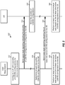
- FIG. 5 shows an exemplary message flow 500 for configuring and activating CSI-RS configurations.
- a cell may configure a UE with a plurality of CSI-RS configurations for one or more purposes (step 512).
- the cell may send upper-layer signaling indicating the plurality of CSI-RS configurations configured for the UE (step 514).
- the UE may receive the upper-layer signaling and may store the plurality of CSI-RS configurations (step 516).
- the cell may determine at least one active CSI-RS configuration for the UE (step 518).
- the cell may send lower-layer signaling indicating the at least one active CSI-RS configuration for the UE (step 520).
- the cell may perform at least one communication task based on the at least one active CSI-RS configuration for the UE (step 522).
- the UE may perform at least one complementary communication task based on the at least one active CSI-RS configuration for the UE (step 524).
- the cell may perform rate matching and the UE may perform de-rate matching based on the at least one active CSI-RS configuration.
- the UE may determine and report CSI and the cell may receive CSI feedback based on the at least one active CSI-RS configuration.
- Active CSI-RS configurations may be determined and applied in various manners.
- a UE may be configured with five sets of CSI-RS configurations via upper-layer signaling.
- the UE may receive lower-layer signaling indicating that only the first two sets of CSI-RS configurations are active in a first subframe and that all five sets of CSI-RS configurations are active in a second subframe.
- the UE may perform communication tasks (e.g., CSI feedback) associated with the first two sets of CSI-RS configurations in the first subframe.
- the UE may perform communication tasks (e.g., CoMP set management) associated with the five sets of CSI-RS configurations in the second subframe.
- the UE may also perform de-rate matching based on the first two sets of CSI-RS configurations in the first subframe and based on the five sets of CSI-RS configurations in the second subframe.
- a UE may be configured with two sets of CSI-RS configurations via upper-layer signaling.
- the first set of CSI-RS configurations may be associated with CSI-RS transmissions every 5 ms and may be present in first and second subframes.
- the second set of CSI-RS configurations may be associated with CSI-RS transmissions every 10 ms and may be present in the first subframe but not the second subframe.
- the UE may receive signaling indicating that the two sets of CSI-RS configurations are active.
- the UE may perform de-rate matching based on the two sets of CSI-RS configurations in the first subframe and based on only the first set of CSI-RS configurations in the second subframe.
- a UE may be configured with a first set of CSI-RS configurations for a first cell and a second set of CSI-RS configuration for a second cell.
- the first and second cells may correspond to two cells in a Node B, two carriers of the same eNB, two cells in two eNBs, etc.
- the UE may receive signaling indicating that only one set of CSI-RS configurations active. The UE may then perform communication tasks related to the active set of CSI-RS configurations.
- Signaling may be sent in various manners to indicate active CSI-RS configurations for a given UE.
- unicast signaling indicating active CSI-RS configurations may be sent specifically to the UE.
- the unicast signaling may be sent (i) when triggered by one or more events, e.g., when there is a change in active CSI-RS configurations for the UE, or (ii) periodically, e.g., in every X subframes, or (iii) prior to or concurrent with transmission of CSI-RS.
- multicast signaling indicating active CSI-RS configurations may be sent to a group of UEs (e.g., in the same cell) that might be affected by the active CSI-RS configurations.
- the group of UEs may monitor a multicast/groupcast channel (e.g., similar to DCI 3/3A group power control sent on the PDCCH in LTE) for signaling indicating active CSI-RS configurations and may perform de-rate matching and/or other communication tasks based on the signaling.
- broadcast signaling indicating active CSI-RS configurations may be sent to all UEs in a cell. All UEs in the cell may monitor a broadcast channel for signaling indicating active CSI-RS configurations.
- the signaling may be broadcast periodically, e.g., every X subframes, where X may be any integer value.
- a base station/cell may send signaling on the PDCCH and/or ePDCCH to indicate which CSI-RS configurations are active.
- MAC-based signaling may be sent to indicate active CSI-RS configurations.
- MAC-based signaling similar to that used to indicate activation/deactivation of a carrier may be sent to indicate active CSI-RS configurations.
- signaling may be sent to indicate semi-persistently active CSI-RS configurations and may be referred to as semi-persistent signaling.
- the semi-persistent signaling for active CSI-RS configurations may be sent in similar manner as semi-persistent scheduling (SPS) signaling used to assign resources to a UE for an extended period of time for traffic data transmission.
- SPS signaling may be used to reduce signaling overhead in comparison to dynamic scheduling in which a resource grant is sent for each transmission of data.
- Semi-persistent signaling may be used to convey active CSI-RS configurations for an extended period of time.
- the active CSI-RS configurations may be valid until a termination time is reached or until signaling is sent to cancel the active CSI-RS configurations.
- signaling may indicate whether each set of CSI-RS configurations is active.
- a UE may be configured with N sets of CSI-RS configurations, where N may be any integer value of one or greater.
- a bitmap of N bits may be defined and may include one bit for each set of CSI-RS configurations configured for the UE. Each bit of the bitmap may be set to (i) a first value (e.g., '1') if the set of CSI-RS configurations associated with that bit is active or (ii) a second value (e.g., '0') if the associated set of CSI-RS configurations is not active.
- sets of CSI-RS configurations for a UE may be organized into groups, with each group including one or more sets of CSI-RS configurations.
- a UE may be configured with N sets of CSI-RS configurations, which may be organized into K groups, where in general 1 ⁇ K ⁇ N .
- Signaling may be sent to indicate which groups of CSI-RS configurations are active.
- a bitmap of K bits may be defined and may include one bit for each group.
- Each bit of the bitmap may be set to (i) a first value (e.g., 'l') if the group of CSI-RS configurations associated with that bit is active or (ii) a second value (e.g., '0') if the associated group of CSI-RS configurations is not active.
- a first value e.g., 'l'
- a second value e.g., '0'
- a UE may have one or more sets of CSI-RS configurations that may always be active for the UE. For example, one set of CSI-RS configurations for CSI channel measurement and one set of CSI-RS configurations for interference measurement may always be active for the UE. As another example, all non-zero-power CSI-RS configurations for the UE may always be active.
- the sets of CSI-RS configurations for the UE may be arranged into (i) a primary group of CSI-RS configurations that is always active for the UE and (ii) one or more secondary groups of CSI-RS configurations that can be activated or deactivated for the UE. Signaling may be sent for only the secondary group(s) to indicate which groups or sets of CSI-RS configurations in the secondary group(s) are active for the UE.
- a UE may perform de-rate matching by taking into account CSI-RS in various manners.
- the UE may perform de-rate matching only for active CSI-RS configurations and not for inactive CSI-RS configurations.
- the UE may perform de-rate matching depending on CSI-RS types.
- Each CSI-RS type may be associated with a different purpose.
- the UE may be configured with one or more sets of CSI-RS configurations for CSI feedback, one or more sets of CSI-RS configurations for CoMP set management, one or more sets of CSI-RS configurations for RLM/RRM, one or more sets of zero-power CSI-RS configurations, one or more sets of non-zero-power CSI-RS configurations, etc.
- CSI-RS configurations of different types may be signaled and/or handled differently for de-rate matching.
- the UE may perform de-rate matching for CSI-RS configurations for CSI feedback and CoMP set management and may not perform de-rate matching for CSI-RS configurations for RLM/RRM.
- a UE may perform de-rate matching for one or more physical channels based on its active CSI-RS configurations and/or configured CSI-RS configurations. For example, the UE may perform de-rate matching for the PDSCH, or the ePDCCH, or both the PDSCH and ePDCCH, or some other physical channel, or any combination of physical channels. The UE may perform de-rate matching in the same manner for all physical channels. Alternatively, the UE may perform de-rate matching in different manners for different physical channels.
- the UE may also perform de-rate matching in different manners for different types of a given physical channel.
- different types of PDSCH may be supported.
- the different PDSCH types may include (i) broadcast PDSCH sent to all UEs versus unicast PDSCH sent to a specific UE, (ii) PDSCH scheduled via a common search space in the control region of a downlink subframe versus PDSCH scheduled via a UE-specific search space in the control region, (iii) PDSCH sent by multiple cells for CoMP versus PDSCH sent by one cell without CoMP, (iv) PDSCH sent in almost blank subframes (ABS) versus PDSCH sent in non-ABS subframes, (v) PDSCH sent without a corresponding control channel (e.g., semi-persistently scheduled PDSCH) versus PDSCH sent with corresponding control channel, and (vi) other types of PDSCH.
- ABS almost blank subframes
- a UE may perform de-rate matching in a similar manner for PDSCH of all types.
- a UE may perform de-rate matching in different manners for different types of PDSCH.
- the UE may perform de-rate matching for a broadcast PDSCH based on all configured CSI-RS configurations for the UE (instead of based on only active CSI-RS configurations).
- the UE may perform de-rate matching for a unicast PDSCH based on only active CSI-RS configurations for the UE.
- the UE may perform de-rate matching for a PDSCH without a corresponding control channel based on all configured CSI-RS configurations.
- the UE may perform de-rate matching for a PDSCH with a corresponding control channel based on only active CSI-RS configurations, which may be indicated via the corresponding control channel.
- a UE may perform de-rate matching for the ePDCCH in various manners. In one example, the UE may perform de-rate matching for the ePDCCH based on only active CSI-RS configurations. In another example, the UE may perform de-rate matching for the ePDCCH based on all configured CSI-RS configurations.
- a UE may perform de-rate matching in similar manner for the PDSCH and ePDCCH. For example, the UE may perform de-rate matching for the PDSCH and ePDCCH based on the active CSI-RS configurations instead of the configured CSI-RS configurations. In another example, the UE may perform de-rate matching in different manners for the PDSCH and ePDCCH. For example, the UE may perform de-rate matching for the PDSCH based on the active CSI-RS configurations and may perform de-rate matching for the ePDCCH based on the configured CSI-RS configurations.
- a UE may be configured with (i) one or more sets of CSI-RS configurations for channel estimation and (ii) one or more sets of CSI-RS configurations for interference estimation.
- the UE may perform channel estimation based on the set(s) of CSI-RS configurations designated for channel estimation and may perform interference estimation based on the set(s) of CSI-RS configurations designated for interference estimation.
- the UE may also perform channel estimation based on the CRS configurations designated for channel estimation and may not be configured with any CSI-RS configurations for interference estimation.
- a UE may be signaled one or more sets of CSI-RS configurations for one or more neighbor cells.
- the UE may estimate interference due to the CSI-RS from the neighbor cell(s) based on the CSI-RS configurations for the neighbor cell(s).
- the UE may cancel the estimated interference due to the CSI-RS from the neighbor cell(s) prior to making channel measurements and/or interference measurements based on the CSI-RS from the serving cell. Interference cancellation of the CSI-RS from the neighbor cell(s) may improve CSI feedback, and CoMP set management, especially in a hyperdense network with many cells.
- a UE may perform decoding for one or more physical channels (e.g., the PDSCH and/or ePDCCH) based on CSI-RS configurations for one or more neighbor cells.
- a serving cell of the UE may not perform rate matching for the PDSCH and/or ePDCCH based on the CSI-RS configurations for the neighbor cell(s) and may transmit the PDSCH and/or ePDCCH on resource elements used for CSI-RS by the neighbor cell(s).
- the UE may cancel the impact of the CSI-RS from the neighbor cell(s) based on the CSI-RS configurations for the neighbor cell(s).
- the UE may estimate interference due to the CSI-RS from the neighbor cell(s) based on the CSI-RS configurations for the neighbor cell(s). The UE may then cancel the estimated interference due to the CSI-RS from the neighbor cell(s) to obtain interference-canceled symbols for the PDSCH and/or ePDCCH. The UE may then decode the interference-canceled symbols to recover data sent on the PDSCH and/or ePDCCH.
- a UE may perform de-rate matching for one or more physical channels based on active CSI-RS configurations, which may change frequently to reflect the dynamics of network operating conditions.
- the UE may perform communication tasks such as de-rate matching, CSI feedback, CoMP set management, etc., based on the active CSI-RS configurations instead of the configured CSI-RS configurations.
- Improved performance may be obtained by performing communication tasks based on the active CSI-RS configurations.
- Improved network efficiency may be obtained with the ability to dynamically select and indicate active CSI-RS configurations.
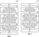
- FIG. 6 shows an exemplary process 600 for receiving CSI-RS.
- Process 600 may be performed by a UE (as described below) or by some other entity.
- the UE may receive first signaling indicating a plurality of CSI-RS configurations configured for the UE (block 612).
- the UE may receive second signaling indicating at least one active CSI-RS configuration for the UE (block 614).
- the at least one active CSI-RS configuration may include all or a subset of the plurality of CSI-RS configurations.
- the second signaling may relate to an individual CSI-RS configuration, or a set of CSI-RS configurations, or a group of CSI-RS configurations.
- the UE may perform at least one communication task based on the at least one active CSI-RS configuration for the UE (block 616).
- the UE may receive upper-layer signaling (e.g., RRC signaling) indicating the plurality of CSI-RS configurations configured for the UE.
- the UE may receive lower-layer signaling indicating the at least one active CSI-RS configuration for the UE.
- the second signaling may comprise control information sent on a physical channel (e.g., the PDCCH or ePDCCH) or via MAC.
- the plurality of CSI-RS configurations may be statically or semi-statically configured for the UE and may change infrequently (e.g., after some minimum number of frames or subframes) or not at all during a communication session for the UE.
- the at least one active CSI-RS configuration may change dynamically (e.g., possibly at subframe level) during the communication session for the UE.
- the second signaling may be sent in various manners.
- the UE may receive the second signaling via a broadcast channel sent to all UEs in a cell, or a unicast channel sent to the UE, or a multicast channel sent to a group of UEs including the UE.
- the UE may also receive signaling conveying the active CSI-RS configurations and the configured CSI-RS configurations in other manners.
- the plurality of CSI-RS configurations may include at least two sets of CSI-RS configurations.
- Each set of CSI-RS configurations may be associated with one or more communication tasks by the UE, e.g., de-rate matching, CSI feedback, CoMP set management, RLM/RRM, etc.
- Each set may include one or more CSI-RS configurations.
- the second signaling may comprise a bitmap with at least two bits for the at least two sets of CSI-RS configurations. Each bit of the bitmap may indicate whether an associated set of CSI-RS configurations is active for the UE.
- At least one group of CSI-RS configurations may be formed based on the at least two sets of CSI-RS configurations.
- Each group of CSI-RS configurations may include at least one set of CSI-RS configurations.
- the second signaling may comprise a bitmap with at least one bit for the at least one group of CSI-RS configurations. Each bit of the bitmap may indicate whether an associated group of CSI-RS configurations is active for the UE.
- the second signaling indicating at least one active CSI-RS configuration for the UE may also be sent in other manners.
- the plurality of CSI-RS configurations may include (i) a first subset of CSI-RS configurations that is always active for the UE and (ii) a second subset of CSI-RS configurations that can be activated or deactivated for the UE.
- the second signaling may indicate at least one active CSI-RS configuration in the second subset of CSI-RS configurations.
- the plurality of CSI-RS configurations may include a CSI-RS configuration that is active for a first communication task (e.g., de-rate matching) and is inactive for a second communication task (e.g., CSI feedback).
- the plurality of CSI-RS configurations may include a CSI-RS configuration that can be activated or deactivated for a first communication task and is always active for a second communication task.
- the plurality of CSI-RS configurations may include a first CSI-RS configuration that can be activated or deactivated for a first communication task and a second CSI-RS configuration that is always active for a second communication task.
- the plurality of CSI-RS configurations may include a first set of CSI-RS configurations for a first cell and a second set of CSI-RS configurations for a second cell.
- the at least one active CSI-RS configuration for the UE may comprise either the first or second set of CSI-RS configurations.
- the active CSI-RS configurations may also be defined in other manners.
- the UE may determine CSI feedback based on the at least one active CSI-RS configuration for the UE. Alternatively or additionally, the UE may perform de-rate matching for at least one physical channel based on the at least one active CSI-RS configuration for the UE. In one example, the UE may perform de-rate matching for a first physical channel (e.g., the PDSCH or unicast PDSCH) based on the at least one active CSI-RS configuration for the UE. The UE may perform de-rate matching for a second physical channel (e.g., the ePDCCH or broadcast PDSCH) based on the plurality of CSI-RS configurations configured for the UE. In another example, the UE may perform de-rate matching in the same manner for the first and second physical channels based on the at least one active CSI-RS configuration. The UE may also estimate interference based on the at least one active CSI-RS configuration for the UE.
- a first physical channel e.g., the PDSCH or uni
- the UE may determine CSI-RS types of the plurality of CSI-RS configurations.
- the UE may perform a communication task (e.g., de-rate matching) by considering CSI-RS configurations of a first CSI-RS type and without considering CSI-RS configurations of a second CSI-RS type.
- the UE may receive signaling indicating at least one CSI-RS configuration for at least one neighbor cell.
- the UE may perform interference cancellation for CSI-RS from the neighbor cell(s) based on the at least one CSI-RS configuration for the neighbor cell(s).
- the UE may determine CSI feedback and/or decode at least one physical channel (e.g., the PDSCH and/or ePDCCH) after performing interference cancellation for the CSI-RS from the neighbor cell(s).
- FIG. 7 shows an exemplary process 700 for sending CSI-RS.
- Process 700 may be performed by a cell/base station (as described below) or by some other entity.
- the cell may send first signaling to configure a UE with a plurality of CSI-RS configurations (block 712).
- the cell may send second signaling to indicate at least one active CSI-RS configuration for the UE (block 714).
- the at least one active CSI-RS configuration may include all or a subset of the plurality of CSI-RS configurations.
- the cell may perform at least one communication task based on the at least one active CSI-RS configuration for the UE (block 716).
- the cell may send upper-layer signaling (e.g., RRC signaling) to configure the UE with the plurality of CSI-RS configurations.
- the cell may send lower-layer signaling to indicate the at least one active CSI-RS configuration for the UE.
- the lower-layer signaling may comprise control information sent on a physical channel (e.g., the PDCCH or ePDCCH) or via MAC.
- the cell may send the second signaling via a broadcast channel sent to all UEs in a cell, or a unicast channel sent to the UE, or a multicast channel sent to a group of UEs including the UE.
- the second signaling may comprise a bitmap with one bit for each set of CSI-RS configurations or one bit for each group of at least one set of CSI-RS configurations.
- the second signaling may also comprise other information.
- the plurality of CSI-RS configurations may include (i) a first subset of CSI-RS configurations that is always active for the UE and (ii) a second subset of CSI-RS configurations that can be activated or deactivated for the UE.
- the second signaling may indicate at least one active CSI-RS configuration in the second subset of CSI-RS configurations.
- the plurality of CSI-RS configurations may include a CSI-RS configuration that is active for a first communication task (e.g., rate matching) and is inactive for a second communication task (e.g., CSI reporting).
- the plurality of CSI-RS configurations may include a CSI-RS configuration that can be activated or deactivated for a first communication task and is always active for a second communication task.
- the plurality of CSI-RS configurations may include (i) a first CSI-RS configuration that can be activated or deactivated for a first communication task and (ii) a second CSI-RS configuration that is always active for a second communication task.
- the plurality of CSI-RS configurations may include a first set of CSI-RS configurations for a first cell and a second set of CSI-RS configurations for a second cell.
- the at least one active CSI-RS configuration for the UE may include either the first or second set of CSI-RS configurations.
- the cell may receive CSI feedback determined by the UE based on the at least one active CSI-RS configuration for the UE.
- the cell may perform rate matching for at least one physical channel based on the at least one active CSI-RS configuration for the UE.
- the cell may perform rate matching for (i) a first physical channel (e.g., the PDSCH or unicast PDSCH) based on the at least one active CSI-RS configuration for the UE and (ii) a second physical channel (e.g., the ePDCCH or broadcast PDSCH) based on the plurality of CSI-RS configurations configured for the UE.
- the cell may perform rate matching in similar manner for the first and second physical channels.
- the cell may determine the CSI-RS types of the plurality of CSI-RS configurations.
- the cell may perform a communication task (e.g., rate matching) based on CSI-RS configurations of a first CSI-RS type and not based on CSI-RS configurations of a second CSI-RS type.
- the cell may send signaling indicating at least one CSI-RS configuration for at least one neighbor cell.
- the UE may perform interference cancellation for CSI-RS from the neighbor cell(s) based on the at least one CSI-RS configuration for the neighbor cell(s).
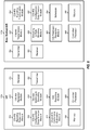
- FIG. 8 shows a block diagram of a UE 130x and a base station/eNB 110x, which may be one of the UEs and one of the eNBs in FIG. 1 .
- a receiver 810 may receive signals transmitted by base stations, relays, etc.
- a module 812 may receive reference signals (e.g., CRS, CSI-RS, etc.) from base station 110x and/or other base stations.
- a module 814 may receive upper-layer signaling conveying CSI-RS configurations configured for UE 130x and lower-layer signaling conveying active CSI-RS configurations for UE 130x.
- a module 816 may determine configured CSI-RS configurations and active CSI-RS configurations for UE 130x based on the received signaling.
- a module 818 may perform de-rate matching based on the active CSI-RS configurations and may perform decoding after de-rate matching.
- a module 822 may perform channel estimation based on active CSI-RS configurations for UE 130x designated for channel estimation. Module 822 may also perform interference estimation based on active CSI-RS configurations designated for interference estimation. Module 818 and/or 822 may perform interference cancellation for CSI-RS from neighbor cells based on CSI-RS configuration for the neighbor cells prior to performing decoding or channel estimation.
- a module 824 may determine CSI feedback based on the measurements for channel estimation and interference estimation. Module 824 may report the CSI for one or more carriers of interest.
- a transmitter 820 may transmit the CSI as well as other information.
- the various modules within UE 130x may operate as described above.
- a controller/processor 828 may direct the operation of various modules within UE 130x.
- a memory 826 may store data and program codes for UE 130x.
- a module 856 may configure UE 130x with CSI-RS configurations and may determine active CSI-RS configurations for UE 130x.
- a module 854 may generate upper-layer signaling conveying the configured CSI-RS configurations and lower-layer signaling conveying the active CSI-RS configurations for UE 130x.
- Module 854 may send the signaling to UE 130x.
- a module 858 may encode data and/or control information sent to UE 130x and may perform rate matching based on the active CSI-RS configurations for UE 130x.
- a module 852 may generate and send CSI-RS based on the active CSI-RS configurations for UE 130x.
- a transmitter 850 may transmit one or more downlink signals comprising CSI-RS, signaling, data, and/or other information.
- a receiver 860 may receive uplink signals transmitted by UE 130x and other UEs.
- a module 862 may receive CSI feedback determined by UE 130x based on the active CSI-RS configurations.
- a module 864 may schedule UE 130x for data transmission based on the CSI.
- the various modules within base station 110x may operate as described above.
- a controller/processor 866 may direct the operation of various modules within base station 110x.
- a memory 868 may store data and program codes for base station 110x.
- the modules in FIG. 8 may comprise processors, electronic devices, hardware devices, electronic components, logical circuits, memories, software codes, firmware codes, etc., or any combination thereof.
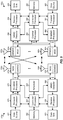
- FIG. 9 shows a block diagram of a base station/eNB 110y and a UE 130y, which may be one of the base stations/eNBs and one of the UEs in FIG. 1 .
- Base station 110y may be equipped with T antennas 934a through 934t
- UE 130y may be equipped with R antennas 952a through 952r, where in general T ⁇ 1 and R ⁇ 1.
- a transmit processor 920 may receive data from a data source 912 for transmission to one or more UEs, process (e.g., encode and modulate) the data for each UE based on one or more modulation and coding schemes selected for that UE, and provide data symbols for all UEs. Transmit processor 920 may also process control information (e.g., scheduling grants, configuration messages, signaling, etc.) and provide control symbols.
- the control information may include upper-layer signaling to configure UE 130y with CSI-RS configurations and lower-layer signaling indicating active CSI-RS configurations for UE 130y.
- Processor 920 may also generate reference symbols for one or more reference signals such as CRS, CSI-RS, etc.
- a transmit (TX) multiple-input multiple-output (MIMO) processor 930 may precode the data symbols, the control symbols, and/or the reference symbols (if applicable) and may provide T output symbol streams to T modulators (MOD) 932a through 932t.
- Each modulator 932 may process its output symbol stream (e.g., for OFDM, etc.) to obtain an output sample stream.
- Each modulator 932 may further condition (e.g., convert to analog, amplify, filter, and upconvert) its output sample stream to obtain a downlink signal.
- T downlink signals from modulators 932a through 932t may be transmitted via T antennas 934a through 934t, respectively.
- antennas 952a through 952r may receive the downlink signals from base station 110y and/or other base stations and may provide received signals to demodulators (DEMODs) 954a through 954r, respectively.
- Each demodulator 954 may condition (e.g., filter, amplify, downconvert, and digitize) its received signal to obtain input samples.
- Each demodulator 954 may further process the input samples (e.g., for OFDM, etc.) to obtain received symbols.
- a MIMO detector 956 may obtain received symbols from all R demodulators 954a through 954r, perform MIMO detection on the received symbols, and provide detected symbols.
- a receive processor 958 may process (e.g., demodulate and decode) the detected symbols to obtain decoded data.
- Receive processor 958 may obtain upper-layer signaling configuring UE 130y with CSI-RS configurations and lower-layer signaling indicating active CSI-RS configurations for UE 130y. Receive processor 958 may perform de-rate matching for the PDSCH, ePDCCH, and/or other physical channels based on active CSI-RS configurations and/or configured CSI-RS configurations for UE 130y. Receive processor 958 may provide decoded data for UE 130y to a data sink 960 and provide decoded control information to a controller/processor 980. A channel processor 984 may perform channel estimation and/or interference estimation for different carriers based on CSI-RS received on these carriers based on the active CSI-RS configurations for UE 130y. Channel processor 984 and/or controller 980 may determine CSI for each carrier of interest based on the measurements for channel estimation and/or interference estimation.
- a transmit processor 964 may receive and process data from a data source 962 and control information (e.g., CSI feedback, etc.) from controller/processor 980. Processor 964 may also generate reference symbols for one or more reference signals. The symbols from transmit processor 964 may be precoded by a TX MIMO processor 966 if applicable, further processed by modulators 954a through 954r (e.g., for SC-FDM, OFDM, etc.), and transmitted to base station 110y.
- modulators 954a through 954r e.g., for SC-FDM, OFDM, etc.
- the uplink signals from UE 130y and other UEs may be received by antennas 934, processed by demodulators 932, detected by a MIMO detector 936 if applicable, and further processed by a receive processor 938 to obtain decoded data and control information sent by UE 130y and other UEs.
- Processor 938 may provide the decoded data to a data sink 939 and the decoded control information to controller/ processor 940.
- Controllers/processors 940 and 980 may direct the operation at base station 110y and UE 130y, respectively.
- Processor 940 and/or other processors and modules at base station 110y may perform or direct process 700 in FIG. 7 , the portion of message flow 500 in FIG. 5 for a cell, and/or other processes for the techniques described herein.
- Processor 980 and/or other processors and modules at UE 130y may perform or direct process 600 in FIG. 6 , the portion of message flow 500 in FIG. 5 for a UE, and/or other processes for the techniques described herein.
- Memories 942 and 982 may store data and program codes for base station 110y and UE 130y, respectively.
- a scheduler 944 may schedule UEs for data transmission on the downlink and/or uplink.
- DSP digital signal processor
- ASIC application specific integrated circuit
- FPGA field programmable gate array
- a general-purpose processor may be a microprocessor, but in the alternative, the processor may be any conventional processor, controller, microcontroller, or state machine.
- a processor may also be implemented as a combination of computing devices, e.g., a combination of a DSP and a microprocessor, a plurality of microprocessors, one or more microprocessors in conjunction with a DSP core, or any other such configuration.
- a software module may reside in RAM memory, flash memory, ROM memory, EPROM memory, EEPROM memory, registers, hard disk, a removable disk, a CD-ROM, or any other form of storage medium known in the art.
- An exemplary storage medium is coupled to the processor such that the processor can read information from, and write information to, the storage medium.
- the storage medium may be integral to the processor.
- the processor and the storage medium may reside in an ASIC.
- the ASIC may reside in a user terminal.
- the processor and the storage medium may reside as discrete components in a user terminal.
- the functions described may be implemented in hardware, software, firmware, or any combination thereof. If implemented in software, the functions may be stored on or transmitted over as one or more instructions or code on a computer-readable medium.
- Computer-readable media includes both computer storage media and communication media including any medium that facilitates transfer of a computer program from one place to another.
- a storage media may be any available media that can be accessed by a general purpose or special purpose computer.
- Such computer-readable media can comprise RAM, ROM, EEPROM, CD-ROM or other optical disk storage, magnetic disk storage or other magnetic storage devices, or any other medium that can be used to carry or store desired program code means in the form of instructions or data structures and that can be accessed by a general-purpose or special-purpose computer, or a general-purpose or special-purpose processor.
- Disk and disc includes compact disc (CD), laser disc, optical disc, digital versatile disc (DVD), floppy disk and blu-ray disc where disks usually reproduce data magnetically, while discs reproduce data optically with lasers. Combinations of the above should also be included within the scope of computer-readable media.
Landscapes
- Engineering & Computer Science (AREA)
- Signal Processing (AREA)
- Computer Networks & Wireless Communication (AREA)
- Mobile Radio Communication Systems (AREA)
Claims (15)
- Verfahren zur drahtlosen Kommunikation, umfassend:Empfangen einer ersten Signalisierung, die eine Vielzahl von Kanalzustandsinformationsreferenzsignal, CSI-RS,-Konfigurationen anzeigt, die für eine Benutzervorrichtung, UE, (130, 130x, 132, 134, 136) konfiguriert sind;Empfangen einer zweiten Signalisierung, die mindestens zwei aktive CSI-RS-Konfigurationen für die UE anzeigt, wobei mindestens eine Teilmenge der Vielzahl von CSI-RS-Konfigurationen aktiv sind, wie durch die zweite Signalisierung angezeigt, wobei die Vielzahl von CSI-RS-Konfigurationen mindestens zwei Sätze von CSI-RS-Konfigurationen umfasst, wobei jeder Satz von CSI-RS-Konfigurationen durch die UE (130, 130x, 132, 134, 136) einer oder mehreren Kommunikationsaufgaben zugeordnet ist, wobei die mindestens zwei Sätze von CSI-RS-Konfigurationen durch die UE (130, 130x, 132, 134, 136) unterschiedlichen Kommunikationsaufgaben zugeordnet sind; undDurchführen einer De-Rate-Anpassung für einen oder mehrere Subframes durch die UE (130, 130x, 132, 134, 136) basierend auf einer der mindestens zwei aktiven CSI-RS-Konfigurationen, die durch die zweite Signalisierung angezeigt werden, und einer anderen Kommunikationsaufgabe für den einen oder die mehreren Subframes basierend auf der anderen der mindestens zwei aktiven CSI-RS-Konfigurationen, die durch die zweite Signalisierung angezeigt werden.
- Verfahren nach Anspruch 1, wobei das Empfangen der ersten Signalisierung Empfangen der Oberlagensignalisierung umfasst, die die Vielzahl von CSI-RS-Konfigurationen anzeigt, die für die UE konfiguriert sind (130, 130x, 132, 134, 136), und wobei das Empfangen der zweiten Signalisierung Empfangen der Unterlagensignalisierung umfasst, die die mindestens zwei aktiven CSI-RS-Konfigurationen für die UE anzeigt (130, 130x, 132, 134, 136).
- Verfahren nach Anspruch 1, wobei die zweite Signalisierung eine Bitmap mit mindestens zwei Bits für die mindestens zwei Sätze von CSI-RS-Konfigurationen umfasst, wobei jedes Bit der Bitmap anzeigt, ob ein zugehöriger Satz von CSI-RS-Konfigurationen für die UE (130, 130x, 132, 134, 136) aktiv ist.
- Verfahren nach Anspruch 1, wobei das Empfangen der zweiten Signalisierung Empfangen der zweiten Signalisierung über einen Broadcast-Kanal umfasst, der an alle UEs (130, 130x, 132, 134, 136) in einer Zelle (112a, 112b, 112c) gesendet wird oder einen Multicast-Kanal, der an eine Gruppe von UEs (130, 130x, 132, 134, 136) einschließlich der UE (130, 130x, 132, 134, 136) gesendet wird.
- Vorrichtung zur drahtlosen Kommunikation, umfassend:Mittel zum Empfangen einer ersten Signalisierung, die eine Vielzahl von Kanalzustandsinformationsreferenzsignal, CSI-RS,-Konfigurationen, die für eine Benutzervorrichtung, UE, (130, 130x, 132, 134, 136) konfiguriert sind, anzeigt;Mittel zum Empfangen einer zweiten Signalisierung, die mindestens zwei aktive CSI-RS-Konfigurationen für die UE (130, 130x, 132, 134, 136) anzeigt, wobei mindestens eine Teilmenge der Vielzahl von CSI-RS-Konfigurationen aktiv sind, wie durch die zweite Signalisierung angezeigt, wobei die Vielzahl von CSI-RS-Konfigurationen mindestens zwei Sätze von CSI-RS-Konfigurationen umfasst, wobei jeder Satz von CSI-RS-Konfigurationen durch die UE (130, 130x, 132, 134, 136) einer oder mehreren Kommunikationsaufgaben zugeordnet ist, wobei die mindestens zwei Sätze von CSI-RS-Konfigurationen durch die UE (130, 130x, 132, 134, 136) unterschiedlichen Kommunikationsaufgaben zugeordnet sind; undMittel zum Ausführen mindestens einer Kommunikationsaufgabe durch die UE (130, 130x, 132, 134, 136) basierend auf den mindestens zwei aktiven CSI-RS-Konfigurationen für die UE (130, 130x, 132, 134, 136);wobei die Vorrichtung angepasst ist, um durch die UE (130, 130x, 132, 134, 136) eine De-Rate-Anpassung für einen oder mehrere Subframes basierend auf der mindestens einen der mindestens zwei aktiven CSI-RS-Konfigurationen, die durch die zweite Signalisierung angezeigt werden, und eine andere Kommunikationsaufgabe für den einen oder die mehreren Subframes basierend auf dem anderen der mindestens zwei aktiven CSI-RS-Konfigurationen, die durch die zweite Signalisierung angezeigt werden, durchzuführen.
- Vorrichtung nach Anspruch 5, wobei die Vielzahl von CSI-RS-Konfigurationen eine erste Teilmenge von CSI-RS-Konfigurationen umfasst, die immer für die UE (130, 130x, 132, 134, 136) aktiv ist, und eine zweite Teilmenge von CSI-RS-Konfigurationen, die für die UE (130, 130x, 132, 134, 136) aktiviert oder deaktiviert werden kann, und wobei das Mittel zum Empfangen der zweiten Signalisierung ein Mittel zum Empfangen der zweiten Signalisierung umfasst, die mindestens eine aktive CSI-RS-Konfiguration in der zweiten Teilmenge von CSI-RS-Konfigurationen anzeigt.
- Vorrichtung nach Anspruch 5, ferner umfassend Mittel zum Bestimmen von CSI-Feedback basierend auf den mindestens zwei aktiven CSI-RS-Konfigurationen für die UE (130, 130x, 132, 134, 136).
- Verfahren zur drahtlosen Kommunikation, umfassend:Senden einer ersten Signalisierung, um eine Benutzervorrichtung, UE, (130, 130x, 132, 134, 136) mit einer Vielzahl von Kanalzustandsinformationsreferenzsignal, CSI-RS,-Konfigurationen zu konfigurieren; undSenden einer zweiten Signalisierung, um mindestens zwei aktive CSI-RS-Konfigurationen für die UE (130, 130x, 132, 134, 136) anzuzeigen, wobei die mindestens zwei aktiven CSI-RS-Konfigurationen alle oder eine Teilmenge der Vielzahl von CSI-RS-Konfigurationen beinhalten, wobei die Vielzahl von CSI-RS-Konfigurationen mindestens zwei Sätze von CSI-RS-Konfigurationen umfasst, wobei jeder Satz von CSI-RS-Konfigurationen einer oder mehreren Kommunikationsaufgaben durch die UE (130, 130x, 132, 134, 136) zugeordnet ist, wobei die mindestens zwei Sätze von CSI-RS-Konfigurationen durch die UE (130, 130x, 132, 134, 136) unterschiedlichen Kommunikationsaufgaben zugeordnet sind, damit die UE (130, 130x, 132, 134, 136) eine De-Rate-Anpassung für einen oder mehrere erste Subframes basierend auf einer der mindestens zwei aktiven CSI-RS-Konfigurationen, die durch die zweite Signalisierung angezeigt werden, und eine andere Kommunikationsaufgabe für den einen oder die mehreren ersten Subframes basierend auf der anderen der mindestens zwei aktiven CSI-RS-Konfigurationen, die durch die zweite Signalisierung angezeigt werden, durchführt.
- Verfahren nach Anspruch 8, wobei das Senden der ersten Signalisierung Senden der Oberlagensignalisierung umfasst, um die UE (130, 130x, 132, 134, 136) mit der Vielzahl von CSI-RS-Konfigurationen zu konfigurieren, und wobei das Senden der zweiten Signalisierung Senden der Unterlagensignalisierung umfasst, um die mindestens eine aktive CSI-RS-Konfiguration für die UE (130, 130x, 132, 134, 136) anzuzeigen.
- Verfahren nach Anspruch 8, wobei die zweite Signalisierung eine Bitmap mit mindestens zwei Bits für die mindestens zwei Sätze von CSI-RS-Konfigurationen umfasst, wobei jedes Bit der Bitmap anzeigt, ob ein zugehöriger Satz von CSI-RS-Konfigurationen für die UE (130, 130x, 132, 134, 136) aktiv ist.
- Verfahren nach Anspruch 8, wobei das Senden der zweiten Signalisierung Senden der zweiten Signalisierung über einen Broadcast-Kanal an alle UEs (130, 130x, 132, 134, 136) in einer Zelle (112a, 112b, 112c) oder einen Multicast-Kanal an eine Gruppe von UEs (130, 130x, 132, 134, 136) einschließlich der UE (130, 130x, 132, 134, 136) umfasst.
- Vorrichtung zur drahtlosen Kommunikation, umfassend:Mittel zum Senden einer ersten Signalisierung, um eine Benutzervorrichtung, UE, (130, 130x, 132, 134, 136) mit einer Vielzahl von Kanalzustandsinformationsreferenzsignal, CSI-RS,-Konfigurationen zu konfigurieren; undMittel zum Senden einer zweiten Signalisierung, um mindestens zwei aktive CSI-RS-Konfigurationen für die UE (130, 130x, 132, 134, 136) anzuzeigen, wobei die mindestens zwei aktiven CSI-RS-Konfigurationen alle oder eine Teilmenge der Vielzahl von CSI-RS-Konfigurationen beinhalten, wobei die Vielzahl von CSI-RS-Konfigurationen mindestens zwei Sätze von CSI-RS-Konfigurationen umfasst, wobei jeder Satz von CSI-RS-Konfigurationen einer oder mehreren Kommunikationsaufgaben durch die UE (130, 130x, 132, 134, 136) zugeordnet ist, wobei die mindestens zwei Sätze von CSI-RS-Konfigurationen durch die UE (130, 130x, 132, 134, 136) unterschiedlichen Kommunikationsaufgaben zugeordnet sind, damit die UE (130, 130x, 132, 134, 136) eine De-Rate-Anpassung für ein oder mehrere Subframes basierend auf einer der beiden aktiven CSI-RS-Konfigurationen, die durch die zweite Signalisierung angezeigt werden, und eine andere Kommunikationsaufgabe für den einen oder die mehreren ersten Subframes basierend auf der anderen der mindestens zwei aktiven CSI-RS-Konfigurationen, die durch die zweite Signalisierung angezeigt werden, durchführt.
- Vorrichtung nach Anspruch 12, wobei die Vielzahl von CSI-RS-Konfigurationen eine erste Teilmenge von CSI-RS-Konfigurationen, die immer für die UE (130, 130x, 132, 134, 136) aktiv ist, und eine zweite Teilmenge von CSI-RS-Konfigurationen, die für die UE (130, 130x, 132, 134, 136) aktiviert oder deaktiviert werden kann, umfasst, und wobei das Mittel zum Senden der zweiten Signalisierung ein Mittel zum Senden der zweiten Signalisierung umfasst, die mindestens eine aktive CSI-RS-Konfiguration in der zweiten Teilmenge von CSI-RS-Konfigurationen anzeigt.
- Vorrichtung nach Anspruch 12, ferner umfassend Mittel zum Empfangen von CSI-Feedback, das durch die UE (130, 130x, 132, 134, 136) basierend auf der mindestens einen aktiven CSI-RS-Konfiguration für die UE bestimmt wird.
- Computerprogramm, umfassend Anweisungen, die, wenn das Programm von einem Computer ausgeführt wird, den Computer veranlassen, die Schritte eines der Ansprüche 1 bis 4 oder 8 bis 11 auszuführen.
Applications Claiming Priority (3)
| Application Number | Priority Date | Filing Date | Title |
|---|---|---|---|
| US201261682594P | 2012-08-13 | 2012-08-13 | |
| US13/831,098 US9456358B2 (en) | 2012-08-13 | 2013-03-14 | Method and apparatus for indicating active channel state information reference signal (CSI-RS) configurations |
| PCT/US2013/054439 WO2014028346A2 (en) | 2012-08-13 | 2013-08-10 | Method and apparatus for indicating active channel state information reference signal (csi-rs) configurations |
Publications (2)
| Publication Number | Publication Date |
|---|---|
| EP2883325A2 EP2883325A2 (de) | 2015-06-17 |
| EP2883325B1 true EP2883325B1 (de) | 2019-10-23 |
Family
ID=50066135
Family Applications (1)
| Application Number | Title | Priority Date | Filing Date |
|---|---|---|---|
| EP13829053.1A Active EP2883325B1 (de) | 2012-08-13 | 2013-08-10 | Verfahren und vorrichtung zur signalisierung von aktiven csi-rs-konfigurationen |
Country Status (6)
| Country | Link |
|---|---|
| US (1) | US9456358B2 (de) |
| EP (1) | EP2883325B1 (de) |
| JP (1) | JP2015524641A (de) |
| KR (1) | KR101760026B1 (de) |
| CN (1) | CN104584476B (de) |
| WO (1) | WO2014028346A2 (de) |
Cited By (1)
| Publication number | Priority date | Publication date | Assignee | Title |
|---|---|---|---|---|
| EP3687095B1 (de) * | 2017-11-17 | 2023-08-09 | Samsung Electronics Co., Ltd. | Verfahren und vorrichtung zur einstellung eines referenzsignals in drahtloskommunikationssystem |
Families Citing this family (75)
| Publication number | Priority date | Publication date | Assignee | Title |
|---|---|---|---|---|
| CN105721129B (zh) * | 2007-09-26 | 2019-04-12 | 华为技术有限公司 | 无线通信系统、基站装置以及移动站装置 |
| EP2605433B1 (de) * | 2010-08-11 | 2019-02-27 | GoldPeak Innovations Inc. | Vorrichtung und verfahren zur übertragung von stummschaltungsinformationen sowie vorrichtung und verfahren zur erfassung eines kanalstatus damit |
| WO2013181394A1 (en) * | 2012-05-31 | 2013-12-05 | Interdigital Patent Holdings, Inc. | Device-to-device (d2d) link adaptation |
| US9496997B2 (en) * | 2012-09-07 | 2016-11-15 | Lg Electronics Inc. | Method and apparatus for measuring channel in wireless communication system |
| CN103973394B (zh) * | 2013-01-25 | 2018-07-17 | 索尼公司 | 公共参考信号的图样通知方法和装置、及确定方法和装置 |
| GB2512653B (en) * | 2013-04-05 | 2018-04-11 | Broadcom Corp | Interference mitigation |
| US9271279B2 (en) * | 2013-05-09 | 2016-02-23 | Sharp Laboratories Of America, Inc. | Channel state measurement and reporting |
| US9819471B2 (en) * | 2013-11-04 | 2017-11-14 | Texas Instruments Incorporated | Method and apparatus for configuration, measurement and reporting of channel state information for LTE TDD with dynamic UL/DL configuration |
| CN106031053B (zh) | 2014-02-18 | 2019-04-12 | Lg电子株式会社 | 无线通信系统中使用用户特定的灵活tdd技术收发信号的方法及其装置 |
| US9973901B2 (en) * | 2014-03-28 | 2018-05-15 | Blackberry Limited | Enhancing group communication services |
| US10187136B2 (en) | 2014-04-28 | 2019-01-22 | Sharp Kabushiki Kaisha | Terminal device, base station device, and communication method |
| EP2983323A1 (de) * | 2014-08-07 | 2016-02-10 | Nokia Technologies Oy | Verfahren und vorrichtung für interferenzverwaltung |
| US9900074B2 (en) * | 2014-08-12 | 2018-02-20 | Qualcomm Incorporated | CSI request procedure in LTE/LTE-A with unlicensed spectrum |
| CN106797649B (zh) * | 2014-10-10 | 2021-06-04 | 瑞典爱立信有限公司 | 与灵活的csi配置和关联反馈有关的系统和方法 |
| CN107210801B (zh) * | 2015-02-05 | 2021-07-02 | Lg 电子株式会社 | 无线通信系统中执行干扰测量的方法及其装置 |
| CN105991222B (zh) * | 2015-02-12 | 2020-05-19 | 中兴通讯股份有限公司 | 配置信息通知方法、获取方法、装置、基站及终端 |
| US10506591B2 (en) | 2015-05-15 | 2019-12-10 | Qualcomm Incorporated | Narrowband definition for enhanced machine type communication |
| US10164747B2 (en) * | 2015-05-29 | 2018-12-25 | Samsung Electronics Co., Ltd. | Method and apparatus for operating MIMO measurement reference signals and feedback |
| CN106470078B (zh) * | 2015-08-19 | 2019-04-26 | 中国移动通信集团公司 | 一种信道状态信息测量和反馈的方法、设备及系统 |
| EP3337286B1 (de) * | 2015-09-16 | 2022-01-12 | Huawei Technologies Co., Ltd. | Verfahren und vorrichtung zur freigabe einer funkressourcensteuerungsverbindung |
| WO2017128175A1 (en) * | 2016-01-28 | 2017-08-03 | Qualcomm Incorporated | Energy efficient csi measurement for fd-mimo |
| US10716020B2 (en) * | 2016-02-23 | 2020-07-14 | Samsung Electronics Co., Ltd. | Method and apparatus for measurement reference signal |
| AU2017244123A1 (en) * | 2016-03-30 | 2018-10-18 | Idac Holdings, Inc. | Systems and methods for reference signal measurements in wireless systems |
| CN107294643B (zh) | 2016-03-31 | 2021-07-02 | 中兴通讯股份有限公司 | 一种信道状态信息反馈和配置的方法和装置 |
| WO2017190273A1 (en) | 2016-05-03 | 2017-11-09 | Qualcomm Incorporated | Dynamic csi-rs transmission for enhanced fd-mimo |
| US10511421B2 (en) * | 2016-05-18 | 2019-12-17 | Qualcomm Incorporated | CSI-RS design with dynamic subframe structure |
| WO2017204737A1 (en) * | 2016-05-23 | 2017-11-30 | Telefonaktiebolaget Lm Ericsson (Publ) | Methods and user equipment for handling communication |
| US10333672B2 (en) * | 2016-07-28 | 2019-06-25 | Qualcomm Incorporated | Semi-persistent measurement reference signal (MRS) configuration |
| MX2019001492A (es) * | 2016-08-10 | 2019-07-10 | Interdigital Patent Holdings Inc | Sistemas y metodos para la transmision de señales de referencia de medicion aperiódica en múltiples sistemas de antena. |
| CN107743042A (zh) * | 2016-08-11 | 2018-02-27 | 华为技术有限公司 | 一种信道状态反馈的方法及装置 |
| CN109691198B (zh) | 2016-08-12 | 2023-06-23 | 瑞典爱立信有限公司 | 两级移动性参考信号配置 |
| WO2018038556A1 (ko) | 2016-08-24 | 2018-03-01 | 삼성전자 주식회사 | 이동 통신 시스템에서의 기준 신호 송신을 위한 방법 및 장치 |
| US20180062801A1 (en) * | 2016-08-24 | 2018-03-01 | Qualcomm Incorporated | Techniques for wireless communications in coordinated multi-point operation |
| KR102684277B1 (ko) * | 2016-08-24 | 2024-07-11 | 삼성전자 주식회사 | 이동 통신 시스템에서의 기준 신호 송신을 위한 방법 및 장치 |
| CN109565701B (zh) * | 2016-09-26 | 2022-04-26 | Lg 电子株式会社 | 无线通信系统中用于干扰测量的方法及其装置 |
| CN107888362B (zh) * | 2016-09-30 | 2022-08-19 | 中兴通讯股份有限公司 | 数据资源映射信息配置的方法及装置、基站、终端及系统 |
| US10334533B2 (en) | 2016-11-02 | 2019-06-25 | At&T Intellectual Property I, L.P. | Non-orthogonal design for channel state information reference signals for a 5G air interface or other next generation network interfaces |
| US11115267B2 (en) * | 2016-11-04 | 2021-09-07 | Telefonaktiebolaget Lm Ericsson (Publ) | Method and device for radio link monitoring |
| EP3965356B1 (de) | 2016-12-08 | 2024-02-21 | Telefonaktiebolaget Lm Ericsson (Publ) | Erhalten und anzeigen einer komponentenkombination zur verwendung für csi-rs |
| CN112788767B (zh) | 2016-12-19 | 2023-06-02 | 华为技术有限公司 | 动态调整波束集合的传输方法、基站及终端 |
| JP2020031248A (ja) * | 2016-12-20 | 2020-02-27 | シャープ株式会社 | 基地局装置、端末装置、通信方法、および、集積回路 |
| WO2018126764A1 (zh) * | 2017-01-06 | 2018-07-12 | 华为技术有限公司 | 一种信息指示的方法、网络设备和终端设备 |
| US10237032B2 (en) * | 2017-01-06 | 2019-03-19 | At&T Intellectual Property I, L.P. | Adaptive channel state information reference signal configurations for a 5G wireless communication network or other next generation network |
| CN108282321B (zh) | 2017-01-06 | 2022-03-29 | 华为技术有限公司 | 一种信息指示的方法、网络设备和终端设备 |
| US10320512B2 (en) | 2017-01-08 | 2019-06-11 | At&T Intellectual Property I, L.P. | Interference cancelation for 5G or other next generation network |
| US10396914B2 (en) * | 2017-01-19 | 2019-08-27 | Qualcomm Incorporated | Reference signal measurement filtering in multi-beam operation |
| WO2018144920A1 (en) * | 2017-02-03 | 2018-08-09 | Ntt Docomo, Inc. | User equipment and wireless communication method |
| CN108400852B (zh) * | 2017-02-06 | 2020-10-30 | 电信科学技术研究院 | 一种大尺度信道参数的指示、确定方法、基站及终端 |
| US10536209B2 (en) * | 2017-03-24 | 2020-01-14 | Qualcomm Incorporated | Techniques for beam discovery and beamforming in wireless communications |
| CN115987354A (zh) * | 2017-03-30 | 2023-04-18 | 上海朗帛通信技术有限公司 | 一种用户设备、基站中的被用于多天线传输的方法和装置 |
| CN108668300B (zh) * | 2017-03-31 | 2021-04-27 | 深圳市中兴微电子技术有限公司 | 一种信道状态信息参考信号的处理方法和装置 |
| CN108696306B (zh) * | 2017-04-06 | 2021-05-25 | 电信科学技术研究院 | 一种csi反馈配置方法、网络侧设备和终端 |
| US11310009B2 (en) * | 2017-05-05 | 2022-04-19 | Qualcomm Incorporated | Reference signal acquisition |
| US10587385B2 (en) * | 2017-06-15 | 2020-03-10 | Qualcomm Incorporated | Techniques and apparatuses for acknowledgement (ACK) / negative acknowledgement (NACK) signaling using a reference signal |
| EP3681079B1 (de) | 2017-09-08 | 2022-12-07 | Wilus Institute of Standards and Technology Inc. | Datenübertragungsverfahren und empfangsverfahren für ein drahtloses kommunikationssystem und vorrichtung damit |
| CN108650711B (zh) * | 2017-10-20 | 2020-02-14 | 华为技术有限公司 | 信道测量方法和用户设备 |
| EP3700254A4 (de) * | 2017-10-20 | 2021-05-19 | NTT DoCoMo, Inc. | Benutzerendgerät und drahtloskommunikationsverfahren |
| CN108964862B (zh) | 2017-11-17 | 2019-11-19 | 华为技术有限公司 | 测量csi-rs的指示方法、网络设备和通信系统 |
| EP3711407A4 (de) | 2017-11-17 | 2021-06-09 | ZTE Corporation | Referenzsignalkonfiguration |
| US11290988B2 (en) | 2018-02-02 | 2022-03-29 | Qualcomm Incorporated | UE indicated timing relation for UL transmission |
| JP2021129126A (ja) * | 2018-04-27 | 2021-09-02 | ソニーグループ株式会社 | 無線通信装置、および、無線通信方法 |
| WO2020022748A1 (ko) * | 2018-07-24 | 2020-01-30 | 엘지전자 주식회사 | 채널 상태 정보를 보고하는 방법 및 이를 위한 장치 |
| US20200107265A1 (en) * | 2018-09-28 | 2020-04-02 | Mediatek Inc. | UE Power Consumption Characteristics and Adaptation to Traffic |
| US20200128427A1 (en) | 2018-10-19 | 2020-04-23 | Mediatek Inc. | Adaptation Framework for UE Power Saving |
| US20210013941A1 (en) * | 2019-07-09 | 2021-01-14 | Qualcomm Incorporated | Channel state information (csi) for unlicensed spectrum |
| CN111294188B (zh) * | 2019-07-16 | 2021-07-27 | 北京紫光展锐通信技术有限公司 | 参考信号信息的确定方法及装置、存储介质、终端 |
| EP4104361A1 (de) * | 2020-02-14 | 2022-12-21 | Telefonaktiebolaget Lm Ericsson (Publ) | Zusätzliche referenzsignale für benutzergeräte in nichtverbundenen zuständen |
| US20230064881A1 (en) * | 2020-02-27 | 2023-03-02 | Lenovo (Beijing) Ltd. | Method and apparatus for wireless communication |
| CN114696982A (zh) | 2020-12-31 | 2022-07-01 | 维沃移动通信有限公司 | 参考信号配置方法、配置装置、电子设备和可读存储介质 |
| JPWO2022162742A1 (de) * | 2021-01-26 | 2022-08-04 | ||
| EP4287693A1 (de) * | 2021-01-26 | 2023-12-06 | Ntt Docomo, Inc. | Endgerät, basisstation und drahtloskommunikationsverfahren |
| WO2023031190A1 (en) * | 2021-08-30 | 2023-03-09 | Telefonaktiebolaget Lm Ericsson (Publ) | Channel state information reference signal enhancements for wireless devices |
| WO2023130482A1 (zh) * | 2022-01-10 | 2023-07-13 | 北京小米移动软件有限公司 | 参考信号可用性指示方法及装置、网元设备、终端及存储介质 |
| KR20240131327A (ko) * | 2022-01-11 | 2024-08-30 | 엘지전자 주식회사 | 무선 통신 시스템에서 무선 신호 송수신 방법 및 장치 |
| EP4336911A1 (de) * | 2022-09-01 | 2024-03-13 | KT Corporation | Verfahren und vorrichtung zur signalisierung für netzwerkenergiesparen |
Family Cites Families (17)
| Publication number | Priority date | Publication date | Assignee | Title |
|---|---|---|---|---|
| KR101523985B1 (ko) * | 2008-12-12 | 2015-05-29 | 삼성전자주식회사 | 무선 통신 시스템에서 단말의 채널 품질 지시자를 이용한 제어 채널 요소 검출 방법 및 장치 |
| KR101750371B1 (ko) * | 2009-12-24 | 2017-07-03 | 삼성전자 주식회사 | 크로스 캐리어 스케쥴링을 지원하는 tdd 통신시스템에서 물리채널의 송수신 타이밍을 정의하는 방법 |
| US9407409B2 (en) | 2010-02-23 | 2016-08-02 | Qualcomm Incorporated | Channel state information reference signals |
| EP2548313B1 (de) * | 2010-03-17 | 2019-05-08 | LG Electronics Inc. | Verfahren und vorrichtung zur bereitstellung der konfigurationsinformationen eines kanalstatusinformations-referenzsignals (csi-rs) in einem drahtlosen kommunikationssystem mit unterstützung mehrerer antennen |
| US8743799B2 (en) | 2010-06-24 | 2014-06-03 | Nokia Siemens Networks Oy | Change of rate matching modes in presence of channel state information reference signal transmission |
| CN102347817B (zh) | 2010-08-02 | 2014-01-08 | 华为技术有限公司 | 通知参考信号配置信息的方法及设备 |
| WO2012020963A2 (en) | 2010-08-13 | 2012-02-16 | Lg Electronics Inc. | Method and base station for transmitting downlink signal and method and equipment for receiving downlink signal |
| US9350506B2 (en) * | 2010-09-30 | 2016-05-24 | Qualcomm Incorporated | Aperiodic SRS for carrier aggregation |
| US9252930B2 (en) | 2011-01-07 | 2016-02-02 | Futurewei Technologies, Inc. | Reference signal transmission and reception method and equipment |
| US10014911B2 (en) | 2011-01-07 | 2018-07-03 | Interdigital Patent Holdings, Inc. | Communicating channel state information (CSI) of multiple transmission points |
| US10200166B2 (en) | 2011-01-17 | 2019-02-05 | Qualcomm Incorporated | Rate matching for coordinated multipoint transmission schemes |
| ES2536895T3 (es) | 2011-02-09 | 2015-05-29 | Telefonaktiebolaget L M Ericsson (Publ) | Configuración de símbolos de recursos dependientes del punto en una célula inalámbrica |
| CN102684850B (zh) | 2011-03-11 | 2017-07-04 | 夏普株式会社 | 信道状态信息反馈方法、用户设备和基站 |
| CN104115422B (zh) * | 2012-02-06 | 2018-09-25 | 英特尔公司 | 用于配置下行链路协作多点通信的信令 |
| KR102217646B1 (ko) * | 2012-05-24 | 2021-02-19 | 삼성전자 주식회사 | 이동 통신 시스템 및 그 이동 통신 시스템에서 채널 송수신 방법 |
| US20130322333A1 (en) * | 2012-05-31 | 2013-12-05 | Mediatek Inc. | Network server, mobile communications device, and method thereof |
| US9912430B2 (en) * | 2012-07-06 | 2018-03-06 | Samsung Electronics Co. Ltd. | Method and apparatus for channel state information feedback reporting |
-
2013
- 2013-03-14 US US13/831,098 patent/US9456358B2/en active Active
- 2013-08-10 CN CN201380042649.3A patent/CN104584476B/zh active Active
- 2013-08-10 WO PCT/US2013/054439 patent/WO2014028346A2/en active Application Filing
- 2013-08-10 EP EP13829053.1A patent/EP2883325B1/de active Active
- 2013-08-10 JP JP2015526748A patent/JP2015524641A/ja active Pending
- 2013-08-10 KR KR1020157006208A patent/KR101760026B1/ko active IP Right Grant
Non-Patent Citations (2)
| Title |
|---|
| RENESAS MOBILE EUROPE LTD: "Signaling of CRS position information", vol. RAN WG1, no. Qingdao, China; 20120813 - 20120817, 5 August 2012 (2012-08-05), XP050661460, Retrieved from the Internet <URL:http://www.3gpp.org/ftp/tsg_ran/WG1_RL1/TSGR1_70/Docs/> [retrieved on 20120805] * |
| ZTE: "Downlink control signaling for CoMP", vol. RAN WG1, no. Qingdao, China; 20120813 - 20120817, 9 August 2012 (2012-08-09), XP050661706, Retrieved from the Internet <URL:http://www.3gpp.org/ftp/tsg_ran/WG1_RL1/TSGR1_70/Docs/> [retrieved on 20120809] * |
Cited By (1)
| Publication number | Priority date | Publication date | Assignee | Title |
|---|---|---|---|---|
| EP3687095B1 (de) * | 2017-11-17 | 2023-08-09 | Samsung Electronics Co., Ltd. | Verfahren und vorrichtung zur einstellung eines referenzsignals in drahtloskommunikationssystem |
Also Published As
| Publication number | Publication date |
|---|---|
| US9456358B2 (en) | 2016-09-27 |
| CN104584476B (zh) | 2018-05-08 |
| WO2014028346A3 (en) | 2014-04-17 |
| KR20150043399A (ko) | 2015-04-22 |
| WO2014028346A2 (en) | 2014-02-20 |
| US20140044040A1 (en) | 2014-02-13 |
| JP2015524641A (ja) | 2015-08-24 |
| EP2883325A2 (de) | 2015-06-17 |
| CN104584476A (zh) | 2015-04-29 |
| KR101760026B1 (ko) | 2017-07-20 |
Similar Documents
| Publication | Publication Date | Title |
|---|---|---|
| EP2883325B1 (de) | Verfahren und vorrichtung zur signalisierung von aktiven csi-rs-konfigurationen | |
| RU2572566C2 (ru) | Передача информации управления в беспроводной сети с агрегацией несущих | |
| US9831994B2 (en) | Method and apparatuses for using channel state information reference signals | |
| US9420576B2 (en) | PDSCH transmission schemes with compact downlink control information (DCI) format in new carrier type (NCT) in LTE | |
| US9036594B2 (en) | Systems and methods for enhancing uplink coverage in interference scenarios | |
| EP2774437B1 (de) | Ressourcenverwaltung für erweiterten pdcch | |
| US9565011B2 (en) | Data transmission with cross-subframe control in a wireless network | |
| EP2918122B1 (de) | Steuerkanalverwaltung für relais-backhaul | |
| EP3255826A1 (de) | Entwurf eines suchraums für e-pdcch in drahtlosen kommunikationsnetzen | |
| US20100309876A1 (en) | Partitioning of control resources for communication in a dominant interference scenario | |
| US20130114495A1 (en) | Physical Channel Characteristics for e-PDCCH in LTE | |
| US20110274060A1 (en) | Subframe-specific search space design for cross-subframe assignments | |
| KR20130064128A (ko) | 다중 비트 ack/nak를 위한 제어 채널 자원들 | |
| EP3539315B1 (de) | Referenzsignalzweckanzeige |
Legal Events
| Date | Code | Title | Description |
|---|---|---|---|
| PUAI | Public reference made under article 153(3) epc to a published international application that has entered the european phase |
Free format text: ORIGINAL CODE: 0009012 |
|
| 17P | Request for examination filed |
Effective date: 20150129 |
|
| AK | Designated contracting states |
Kind code of ref document: A2 Designated state(s): AL AT BE BG CH CY CZ DE DK EE ES FI FR GB GR HR HU IE IS IT LI LT LU LV MC MK MT NL NO PL PT RO RS SE SI SK SM TR |
|
| AX | Request for extension of the european patent |
Extension state: BA ME |
|
| DAX | Request for extension of the european patent (deleted) | ||
| STAA | Information on the status of an ep patent application or granted ep patent |
Free format text: STATUS: EXAMINATION IS IN PROGRESS |
|
| 17Q | First examination report despatched |
Effective date: 20171208 |
|
| REG | Reference to a national code |
Ref country code: DE Ref legal event code: R079 Ref document number: 602013062082 Country of ref document: DE Free format text: PREVIOUS MAIN CLASS: H04L0005000000 Ipc: H04J0011000000 |
|
| RIC1 | Information provided on ipc code assigned before grant |
Ipc: H04J 11/00 20060101AFI20190211BHEP Ipc: H04L 5/00 20060101ALI20190211BHEP Ipc: H04L 5/14 20060101ALI20190211BHEP Ipc: H04W 28/22 20090101ALI20190211BHEP |
|
| GRAP | Despatch of communication of intention to grant a patent |
Free format text: ORIGINAL CODE: EPIDOSNIGR1 |
|
| STAA | Information on the status of an ep patent application or granted ep patent |
Free format text: STATUS: GRANT OF PATENT IS INTENDED |
|
| INTG | Intention to grant announced |
Effective date: 20190429 |
|
| GRAS | Grant fee paid |
Free format text: ORIGINAL CODE: EPIDOSNIGR3 |
|
| GRAA | (expected) grant |
Free format text: ORIGINAL CODE: 0009210 |
|
| STAA | Information on the status of an ep patent application or granted ep patent |
Free format text: STATUS: THE PATENT HAS BEEN GRANTED |
|
| AK | Designated contracting states |
Kind code of ref document: B1 Designated state(s): AL AT BE BG CH CY CZ DE DK EE ES FI FR GB GR HR HU IE IS IT LI LT LU LV MC MK MT NL NO PL PT RO RS SE SI SK SM TR |
|
| REG | Reference to a national code |
Ref country code: GB Ref legal event code: FG4D |
|
| REG | Reference to a national code |
Ref country code: CH Ref legal event code: EP |
|
| REG | Reference to a national code |
Ref country code: IE Ref legal event code: FG4D |
|
| REG | Reference to a national code |
Ref country code: DE Ref legal event code: R096 Ref document number: 602013062082 Country of ref document: DE |
|
| REG | Reference to a national code |
Ref country code: AT Ref legal event code: REF Ref document number: 1194875 Country of ref document: AT Kind code of ref document: T Effective date: 20191115 |
|
| REG | Reference to a national code |
Ref country code: NL Ref legal event code: MP Effective date: 20191023 |
|
| REG | Reference to a national code |
Ref country code: LT Ref legal event code: MG4D |
|
| PG25 | Lapsed in a contracting state [announced via postgrant information from national office to epo] |
Ref country code: SE Free format text: LAPSE BECAUSE OF FAILURE TO SUBMIT A TRANSLATION OF THE DESCRIPTION OR TO PAY THE FEE WITHIN THE PRESCRIBED TIME-LIMIT Effective date: 20191023 Ref country code: LV Free format text: LAPSE BECAUSE OF FAILURE TO SUBMIT A TRANSLATION OF THE DESCRIPTION OR TO PAY THE FEE WITHIN THE PRESCRIBED TIME-LIMIT Effective date: 20191023 Ref country code: NL Free format text: LAPSE BECAUSE OF FAILURE TO SUBMIT A TRANSLATION OF THE DESCRIPTION OR TO PAY THE FEE WITHIN THE PRESCRIBED TIME-LIMIT Effective date: 20191023 Ref country code: LT Free format text: LAPSE BECAUSE OF FAILURE TO SUBMIT A TRANSLATION OF THE DESCRIPTION OR TO PAY THE FEE WITHIN THE PRESCRIBED TIME-LIMIT Effective date: 20191023 Ref country code: BG Free format text: LAPSE BECAUSE OF FAILURE TO SUBMIT A TRANSLATION OF THE DESCRIPTION OR TO PAY THE FEE WITHIN THE PRESCRIBED TIME-LIMIT Effective date: 20200123 Ref country code: ES Free format text: LAPSE BECAUSE OF FAILURE TO SUBMIT A TRANSLATION OF THE DESCRIPTION OR TO PAY THE FEE WITHIN THE PRESCRIBED TIME-LIMIT Effective date: 20191023 Ref country code: GR Free format text: LAPSE BECAUSE OF FAILURE TO SUBMIT A TRANSLATION OF THE DESCRIPTION OR TO PAY THE FEE WITHIN THE PRESCRIBED TIME-LIMIT Effective date: 20200124 Ref country code: PL Free format text: LAPSE BECAUSE OF FAILURE TO SUBMIT A TRANSLATION OF THE DESCRIPTION OR TO PAY THE FEE WITHIN THE PRESCRIBED TIME-LIMIT Effective date: 20191023 Ref country code: NO Free format text: LAPSE BECAUSE OF FAILURE TO SUBMIT A TRANSLATION OF THE DESCRIPTION OR TO PAY THE FEE WITHIN THE PRESCRIBED TIME-LIMIT Effective date: 20200123 Ref country code: PT Free format text: LAPSE BECAUSE OF FAILURE TO SUBMIT A TRANSLATION OF THE DESCRIPTION OR TO PAY THE FEE WITHIN THE PRESCRIBED TIME-LIMIT Effective date: 20200224 Ref country code: FI Free format text: LAPSE BECAUSE OF FAILURE TO SUBMIT A TRANSLATION OF THE DESCRIPTION OR TO PAY THE FEE WITHIN THE PRESCRIBED TIME-LIMIT Effective date: 20191023 |
|
| PG25 | Lapsed in a contracting state [announced via postgrant information from national office to epo] |
Ref country code: IS Free format text: LAPSE BECAUSE OF FAILURE TO SUBMIT A TRANSLATION OF THE DESCRIPTION OR TO PAY THE FEE WITHIN THE PRESCRIBED TIME-LIMIT Effective date: 20200224 Ref country code: HR Free format text: LAPSE BECAUSE OF FAILURE TO SUBMIT A TRANSLATION OF THE DESCRIPTION OR TO PAY THE FEE WITHIN THE PRESCRIBED TIME-LIMIT Effective date: 20191023 Ref country code: RS Free format text: LAPSE BECAUSE OF FAILURE TO SUBMIT A TRANSLATION OF THE DESCRIPTION OR TO PAY THE FEE WITHIN THE PRESCRIBED TIME-LIMIT Effective date: 20191023 |
|
| PG25 | Lapsed in a contracting state [announced via postgrant information from national office to epo] |
Ref country code: AL Free format text: LAPSE BECAUSE OF FAILURE TO SUBMIT A TRANSLATION OF THE DESCRIPTION OR TO PAY THE FEE WITHIN THE PRESCRIBED TIME-LIMIT Effective date: 20191023 |
|
| REG | Reference to a national code |
Ref country code: DE Ref legal event code: R097 Ref document number: 602013062082 Country of ref document: DE |
|
| PG2D | Information on lapse in contracting state deleted |
Ref country code: IS |
|
| PG25 | Lapsed in a contracting state [announced via postgrant information from national office to epo] |
Ref country code: CZ Free format text: LAPSE BECAUSE OF FAILURE TO SUBMIT A TRANSLATION OF THE DESCRIPTION OR TO PAY THE FEE WITHIN THE PRESCRIBED TIME-LIMIT Effective date: 20191023 Ref country code: RO Free format text: LAPSE BECAUSE OF FAILURE TO SUBMIT A TRANSLATION OF THE DESCRIPTION OR TO PAY THE FEE WITHIN THE PRESCRIBED TIME-LIMIT Effective date: 20191023 Ref country code: DK Free format text: LAPSE BECAUSE OF FAILURE TO SUBMIT A TRANSLATION OF THE DESCRIPTION OR TO PAY THE FEE WITHIN THE PRESCRIBED TIME-LIMIT Effective date: 20191023 Ref country code: EE Free format text: LAPSE BECAUSE OF FAILURE TO SUBMIT A TRANSLATION OF THE DESCRIPTION OR TO PAY THE FEE WITHIN THE PRESCRIBED TIME-LIMIT Effective date: 20191023 Ref country code: IS Free format text: LAPSE BECAUSE OF FAILURE TO SUBMIT A TRANSLATION OF THE DESCRIPTION OR TO PAY THE FEE WITHIN THE PRESCRIBED TIME-LIMIT Effective date: 20200223 |
|
| REG | Reference to a national code |
Ref country code: AT Ref legal event code: MK05 Ref document number: 1194875 Country of ref document: AT Kind code of ref document: T Effective date: 20191023 |
|
| PLBE | No opposition filed within time limit |
Free format text: ORIGINAL CODE: 0009261 |
|
| STAA | Information on the status of an ep patent application or granted ep patent |
Free format text: STATUS: NO OPPOSITION FILED WITHIN TIME LIMIT |
|
| PG25 | Lapsed in a contracting state [announced via postgrant information from national office to epo] |
Ref country code: SK Free format text: LAPSE BECAUSE OF FAILURE TO SUBMIT A TRANSLATION OF THE DESCRIPTION OR TO PAY THE FEE WITHIN THE PRESCRIBED TIME-LIMIT Effective date: 20191023 Ref country code: SM Free format text: LAPSE BECAUSE OF FAILURE TO SUBMIT A TRANSLATION OF THE DESCRIPTION OR TO PAY THE FEE WITHIN THE PRESCRIBED TIME-LIMIT Effective date: 20191023 Ref country code: IT Free format text: LAPSE BECAUSE OF FAILURE TO SUBMIT A TRANSLATION OF THE DESCRIPTION OR TO PAY THE FEE WITHIN THE PRESCRIBED TIME-LIMIT Effective date: 20191023 |
|
| 26N | No opposition filed |
Effective date: 20200724 |
|
| PG25 | Lapsed in a contracting state [announced via postgrant information from national office to epo] |
Ref country code: AT Free format text: LAPSE BECAUSE OF FAILURE TO SUBMIT A TRANSLATION OF THE DESCRIPTION OR TO PAY THE FEE WITHIN THE PRESCRIBED TIME-LIMIT Effective date: 20191023 Ref country code: SI Free format text: LAPSE BECAUSE OF FAILURE TO SUBMIT A TRANSLATION OF THE DESCRIPTION OR TO PAY THE FEE WITHIN THE PRESCRIBED TIME-LIMIT Effective date: 20191023 |
|
| PG25 | Lapsed in a contracting state [announced via postgrant information from national office to epo] |
Ref country code: MC Free format text: LAPSE BECAUSE OF FAILURE TO SUBMIT A TRANSLATION OF THE DESCRIPTION OR TO PAY THE FEE WITHIN THE PRESCRIBED TIME-LIMIT Effective date: 20191023 |
|
| REG | Reference to a national code |
Ref country code: CH Ref legal event code: PL |
|
| PG25 | Lapsed in a contracting state [announced via postgrant information from national office to epo] |
Ref country code: LU Free format text: LAPSE BECAUSE OF NON-PAYMENT OF DUE FEES Effective date: 20200810 Ref country code: CH Free format text: LAPSE BECAUSE OF NON-PAYMENT OF DUE FEES Effective date: 20200831 Ref country code: LI Free format text: LAPSE BECAUSE OF NON-PAYMENT OF DUE FEES Effective date: 20200831 |
|
| REG | Reference to a national code |
Ref country code: BE Ref legal event code: MM Effective date: 20200831 |
|
| PG25 | Lapsed in a contracting state [announced via postgrant information from national office to epo] |
Ref country code: BE Free format text: LAPSE BECAUSE OF NON-PAYMENT OF DUE FEES Effective date: 20200831 Ref country code: IE Free format text: LAPSE BECAUSE OF NON-PAYMENT OF DUE FEES Effective date: 20200810 |
|
| PG25 | Lapsed in a contracting state [announced via postgrant information from national office to epo] |
Ref country code: TR Free format text: LAPSE BECAUSE OF FAILURE TO SUBMIT A TRANSLATION OF THE DESCRIPTION OR TO PAY THE FEE WITHIN THE PRESCRIBED TIME-LIMIT Effective date: 20191023 Ref country code: MT Free format text: LAPSE BECAUSE OF FAILURE TO SUBMIT A TRANSLATION OF THE DESCRIPTION OR TO PAY THE FEE WITHIN THE PRESCRIBED TIME-LIMIT Effective date: 20191023 Ref country code: CY Free format text: LAPSE BECAUSE OF FAILURE TO SUBMIT A TRANSLATION OF THE DESCRIPTION OR TO PAY THE FEE WITHIN THE PRESCRIBED TIME-LIMIT Effective date: 20191023 |
|
| PG25 | Lapsed in a contracting state [announced via postgrant information from national office to epo] |
Ref country code: MK Free format text: LAPSE BECAUSE OF FAILURE TO SUBMIT A TRANSLATION OF THE DESCRIPTION OR TO PAY THE FEE WITHIN THE PRESCRIBED TIME-LIMIT Effective date: 20191023 |
|
| PGFP | Annual fee paid to national office [announced via postgrant information from national office to epo] |
Ref country code: GB Payment date: 20230712 Year of fee payment: 11 |
|
| PGFP | Annual fee paid to national office [announced via postgrant information from national office to epo] |
Ref country code: FR Payment date: 20230710 Year of fee payment: 11 Ref country code: DE Payment date: 20230425 Year of fee payment: 11 |