EP2883087B1 - Verfahren zur verbesserung der bestimmung eines seismischen horizonts - Google Patents
Verfahren zur verbesserung der bestimmung eines seismischen horizonts Download PDFInfo
- Publication number
- EP2883087B1 EP2883087B1 EP13745135.7A EP13745135A EP2883087B1 EP 2883087 B1 EP2883087 B1 EP 2883087B1 EP 13745135 A EP13745135 A EP 13745135A EP 2883087 B1 EP2883087 B1 EP 2883087B1
- Authority
- EP
- European Patent Office
- Prior art keywords
- horizon
- pseudo
- points
- rectangle
- related control
- Prior art date
- Legal status (The legal status is an assumption and is not a legal conclusion. Google has not performed a legal analysis and makes no representation as to the accuracy of the status listed.)
- Active
Links
- 238000000034 method Methods 0.000 title claims description 92
- 230000002708 enhancing effect Effects 0.000 title claims description 5
- 238000004422 calculation algorithm Methods 0.000 claims description 64
- 230000009466 transformation Effects 0.000 claims description 59
- 230000001131 transforming effect Effects 0.000 claims description 15
- 238000012545 processing Methods 0.000 claims description 10
- 238000004590 computer program Methods 0.000 claims description 9
- 238000012986 modification Methods 0.000 claims description 9
- 230000004048 modification Effects 0.000 claims description 9
- 238000003860 storage Methods 0.000 claims description 2
- 230000000875 corresponding effect Effects 0.000 description 31
- 230000006870 function Effects 0.000 description 29
- 238000004364 calculation method Methods 0.000 description 14
- 238000013459 approach Methods 0.000 description 6
- 230000008901 benefit Effects 0.000 description 6
- 238000000844 transformation Methods 0.000 description 5
- 239000011159 matrix material Substances 0.000 description 4
- 238000005457 optimization Methods 0.000 description 4
- 238000009826 distribution Methods 0.000 description 3
- 238000005304 joining Methods 0.000 description 3
- 230000008859 change Effects 0.000 description 2
- 230000001965 increasing effect Effects 0.000 description 2
- 238000005259 measurement Methods 0.000 description 2
- 239000000203 mixture Substances 0.000 description 2
- 230000008569 process Effects 0.000 description 2
- 239000010749 BS 2869 Class C1 Substances 0.000 description 1
- 239000010750 BS 2869 Class C2 Substances 0.000 description 1
- 238000012937 correction Methods 0.000 description 1
- 230000002596 correlated effect Effects 0.000 description 1
- 230000001419 dependent effect Effects 0.000 description 1
- 239000006185 dispersion Substances 0.000 description 1
- 238000002592 echocardiography Methods 0.000 description 1
- 230000000694 effects Effects 0.000 description 1
- 238000007429 general method Methods 0.000 description 1
- 230000006872 improvement Effects 0.000 description 1
- 230000003993 interaction Effects 0.000 description 1
- 238000013507 mapping Methods 0.000 description 1
- 239000003921 oil Substances 0.000 description 1
- 230000000135 prohibitive effect Effects 0.000 description 1
- 230000009467 reduction Effects 0.000 description 1
- 229910052710 silicon Inorganic materials 0.000 description 1
- 239000010703 silicon Substances 0.000 description 1
- 239000007787 solid Substances 0.000 description 1
- 238000012360 testing method Methods 0.000 description 1
Images

Classifications
-
- G—PHYSICS
- G06—COMPUTING; CALCULATING OR COUNTING
- G06T—IMAGE DATA PROCESSING OR GENERATION, IN GENERAL
- G06T17/00—Three dimensional [3D] modelling, e.g. data description of 3D objects
- G06T17/05—Geographic models
-
- G—PHYSICS
- G01—MEASURING; TESTING
- G01V—GEOPHYSICS; GRAVITATIONAL MEASUREMENTS; DETECTING MASSES OR OBJECTS; TAGS
- G01V1/00—Seismology; Seismic or acoustic prospecting or detecting
- G01V1/28—Processing seismic data, e.g. analysis, for interpretation, for correction
- G01V1/30—Analysis
-
- G—PHYSICS
- G06—COMPUTING; CALCULATING OR COUNTING
- G06T—IMAGE DATA PROCESSING OR GENERATION, IN GENERAL
- G06T17/00—Three dimensional [3D] modelling, e.g. data description of 3D objects
- G06T17/10—Constructive solid geometry [CSG] using solid primitives, e.g. cylinders, cubes
-
- G—PHYSICS
- G01—MEASURING; TESTING
- G01V—GEOPHYSICS; GRAVITATIONAL MEASUREMENTS; DETECTING MASSES OR OBJECTS; TAGS
- G01V2210/00—Details of seismic processing or analysis
- G01V2210/60—Analysis
- G01V2210/64—Geostructures, e.g. in 3D data cubes
- G01V2210/643—Horizon tracking
-
- G—PHYSICS
- G06—COMPUTING; CALCULATING OR COUNTING
- G06T—IMAGE DATA PROCESSING OR GENERATION, IN GENERAL
- G06T2207/00—Indexing scheme for image analysis or image enhancement
- G06T2207/20—Special algorithmic details
- G06T2207/20036—Morphological image processing
- G06T2207/20041—Distance transform
-
- G—PHYSICS
- G06—COMPUTING; CALCULATING OR COUNTING
- G06T—IMAGE DATA PROCESSING OR GENERATION, IN GENERAL
- G06T2207/00—Indexing scheme for image analysis or image enhancement
- G06T2207/20—Special algorithmic details
- G06T2207/20048—Transform domain processing
-
- G—PHYSICS
- G06—COMPUTING; CALCULATING OR COUNTING
- G06T—IMAGE DATA PROCESSING OR GENERATION, IN GENERAL
- G06T2207/00—Indexing scheme for image analysis or image enhancement
- G06T2207/20—Special algorithmic details
- G06T2207/20068—Projection on vertical or horizontal image axis
-
- G—PHYSICS
- G06—COMPUTING; CALCULATING OR COUNTING
- G06T—IMAGE DATA PROCESSING OR GENERATION, IN GENERAL
- G06T2207/00—Indexing scheme for image analysis or image enhancement
- G06T2207/30—Subject of image; Context of image processing
- G06T2207/30181—Earth observation
Definitions
- the invention pertains to the field of methods implemented in order to determine seismic horizons.
- the invention more specifically relates to a method that enhances the determination of a seismic horizon without suffering from some of the drawbacks of the prior art.
- Geological surveys involving generators of seismic waves and detectors of their reflections in the ground are often conducted to determine the position of oil reservoirs and/or to get to know the composition and thickness of the many layers that form the underground.
- Seismic reflection techniques consist in generating a seismic wave that propagates through the ground and reflects at the interfaces thereof. A precise measurement of these echoes and more specifically of their arrival times enables a determination of the shape, depth and composition of the layers that the seismic waves went through.
- image generation algorithms are used to reconstruct a raw picture of the underground in the form of seismic images, sometimes also referred to as echographic images. These images can be either two-dimensional in shape or three-dimensional. Such seismic images comprise pixels the intensity of which is correlated to a seismic wave amplitude, dependent on the local impedance variation.
- Geophysicists are used to manipulating such seismic images displaying information relating to amplitude. By merely looking at such seismic images, a geophysicist is capable of identifying areas of the underground having distinct characteristics, and use these to determine the corresponding structure of the underground.
- the method disclosed in this article considers a global approach by solving a two-dimensional nonlinear partial derivative equation relied on local dip.
- the partial derivative equation is solved using a Gauss-Newton approach by an iterative algorithm whose crucial step is the resolution of a Poisson equation.
- the approach is global in that it systematically computes a seismic horizon on the entire domain of the seismic image, no matter the number of related control points received as input.
- the high computational cost of the horizon reconstruction algorithm implemented by Lomask is further increased by the computational means for solving the Poisson equation that forms the core step of the iterative algorithm.
- another iterative algorithm may be used to solve the Poisson equation.
- the method disclosed by Lomask therefore comprises an iterative algorithm within another iterative algorithm.
- the invention provides a method for enhancing the determination, from a seismic image, of at least a portion of a seismic horizon in a three-dimensional domain comprising axes X , Y , Z .
- the seismic horizon is a function of coordinates along axes X , Y .
- the method comprises:
- the invention consists in, for each current pseudo-rectangle among the defined pseudo-rectangles:
- pseudo-rectangle is used to refer to any quadrangle or quadrilateral that has a convex shape, that is to say that each of its inner angles is smaller than 180°.
- Simple diffeomorphic transformations can be used to transform a convex quadrangle into a rectangle.
- Axes X , Y , Z are used to define corresponding coordinates x, y and z for each point in the three-dimensional domain.
- any point belonging to the reference plane will be referred to using the adjective reference, e.g. a reference center, and the corresponding points on the seismic horizon having the same x and y coordinates will be referred to using the adjective related, e.g. a related central point.
- One advantageous feature of the invention resides in the definition of pseudo-rectangles that delimit portions of the three-dimensional domain.
- Each of these portions has a pseudo-rectangular section and comprises points in the vicinity of a related control point.
- a horizon reconstruction algorithm is applied to the points of these portions of the three-dimensional domain.
- the combined volume of these portions corresponding to the sum of all the volumes of the portions defined by pseudo-rectangles, may be smaller than the volume of the domain corresponding to the entire seismic image. This reduction in volume provides a first enhancement of the computational speed of the horizon reconstruction algorithm.
- a second advantageous feature of the invention is that it provides fast means for solving the Poisson equation, the latter generally implementing an iterative algorithm within the horizon reconstruction algorithm.
- the invention introduces for each previously defined pseudo-rectangle, a corresponding diffeomorphic transformation F which transforms each pseudo-rectangle into a corresponding rectangle in a transformed reference plane defined by axes X' and Y'.
- the same diffeomorphic transformation F also transforms the points of the corresponding portion of the three-dimensional domain into transformed points which are within a transformed portion of the three-dimensional domain delimited by the corresponding rectangle.
- the purpose of this transformation is to meet some conditions in which the Poisson equation can be solved in one step, i.e. using direct calculation techniques that do not rely on an iterative algorithm. It is known, by a man skilled in the art of solving Poisson equations on discrete systems, that at least two conditions can be met to enable such a fast computation:
- the diffeomorphic transformation of pseudo-rectangles into rectangles ensures that the first condition is met.
- the diffeomorphic transformation associated with a pseudo-rectangle is applied to all the points of the seismic image whose coordinates along axes X and Y match those of points in the pseudo-rectangle.
- the coordinates along axis Z are not affected by that transformation.
- the second condition is met by defining pseudo-rectangles that comprise reference points associated with related control points received as input and the coordinates of which are known.
- each diffeomorphic transformation is applied to the portion of the seismic image comprising points having the same x and y coordinates as points in the pseudo-rectangles. Therefore, it may not be necessary to replace the Laplace operator of the Poisson equation by a differential operator with variable coefficients, which would render the resolution of the Poisson equation complex.
- the divergence operator and the fixed function r are the ones that are transformed, thereby enabling the implementation of fast solvers and not necessarily matrix methods.
- Another original feature of this invention is the possibility of choosing pseudo-rectangles delimiting portions of the three-dimensional domain having any section suitable for encompassing the received related control points.
- This is particularly interesting in situations where the related control points are inhomogeneously scattered in the three-dimensional domain, with areas locally having higher concentrations of related control points.
- defining a portion of the three-dimensional domain with a rectangular section may prove difficult insofar as it may require defining rectangles with small dimensions, sometimes referred to as degenerated rectangles.
- Horizon reconstruction algorithms might suffer from an insufficient number of data points in portions delimited by such degenerated rectangles and provide less accurate results.
- the use of pseudo-rectangles gives more freedom in choosing shapes adapted to the local distribution of related control points without suffering from the disadvantages that arise when defining portions of the three-dimensional domain delimited by rectangles.
- a pseudo-rectangle is defined so that the reference point comprised in a pseudo-rectangle belongs to a current reference edge of said pseudo-rectangle.
- the portion of a seismic horizon is determined by first determining the boundaries of the portion of the domain delimited by the current pseudo-rectangle. Having a reference point on a current reference edge may increase the efficiency of the algorithm by providing means for calculating these boundaries of the seismic horizon. Indeed, when a reference point belongs to a current reference edge of a pseudo-rectangle, the associated related control point belongs to a related edge of the seismic horizon. It may then be possible to implement a calculation of the boundaries on the sought seismic horizon.
- a further improvement of the method of the invention may consist in choosing advantageous methods for finding boundary conditions in the portion of the three-dimensional domain delimited by a pseudo-rectangle comprising reference points on a current reference edge.
- the method may comprise applying, for each current pseudo-rectangle comprising a reference point belonging to a current reference edge of said pseudo-rectangle among the defined pseudo-rectangles, for each current reference edge of said current pseudo-rectangle, a horizon reconstruction algorithm to edge points having coordinates along axes X , Y identical to the coordinates along axes X , Y of reference edge points of said current reference edge.
- the horizon reconstruction algorithm implemented to compute these boundary conditions may be a simplified algorithm insofar as its solutions are functions that can be graphically represented in two dimensions as lines.
- a first current reference edge may advantageously be chosen as being the one comprising the reference point associated with the related control point.
- a first horizon line comprising said related control point and forming a first related edge associated with reference edge points of the first current reference edge may be determined.
- the extremities of this first related edge may be used to determine, respectively, a second and third related edge, by implementing horizon reconstruction algorithms in a similar fashion on points of faces of the portion of the three-dimensional domain delimited by the current pseudo-rectangle associated with reference edge points of a second and third current reference edge.
- Two extremities of the second and third related edge may correspond to extremities of a fourth related edge. Therefore the fourth related edge may be determined by implementing a horizon reconstruction algorithm on edge points of a face associated with a fourth current reference edge, with the condition that the horizon line passes through both extremities of the fourth related edge.
- Some techniques for defining pseudo-rectangles may be particularly advantageous, may further reduce the computation time of the algorithm, and may be easy to implement.
- pseudo-rectangles such that at least one reference corner of each pseudo-rectangle among the defined pseudo-rectangles may have coordinates along axes X , Y identical to the coordinates along axes X , Y of a related control point among the plurality of related control points.
- each pseudo-rectangle among the defined pseudo-rectangles may have a reference corner associated with a related control point, thus enabling an easy calculation of the boundary conditions, for example by applying successive horizon reconstruction algorithms to points of faces of the portion of the three-dimensional domain comprising a reference edge comprising said corner and axis Z .
- the received plurality of related control points may comprise at least three related control points, and defining pseudo-rectangles comprises:
- Such a method of defining pseudo-rectangles may provide several advantages. First of all, it can be easily implemented by a computer program, no matter the distribution of the related control points. Secondly, this method may optimize the size distribution of the pseudo-rectangles, since the area of the pseudo-rectangles that are part of a given triangle is substantially the same. Thirdly, this way of defining pseudo-rectangles may greatly facilitate the determination of boundary conditions, since a reference corner of each pseudo-rectangle is associated with a related control point, and the triangles define lines joining reference points. These lines enable an easy calculation of the corresponding horizon line by applying a horizon reconstruction algorithm to points of a plane comprising axis Z and two of the related control points.
- the method of the invention may advantageously comprise, for an identified triangle, and prior to applying a diffeomorphic transformation F:
- the computation of the z coordinate of the related middle point can be a function of any point belonging to the first or second local horizon.
- it could advantageously be a function of one of the extremities of the first or second local horizons, or either related central point.
- the method described above may benefit from one major advantage: it may be particularly efficient from a computational point of view because many steps are implemented once for a first identified triangle, but can be skipped when applying the method to points associated with adjacent triangles. This more specifically concerns the portions of local horizons joining two related control points associated with two reference corners of a triangle. These portions of local horizons may be shared by two adjacent portions of the three-dimensional domain delimited by two adjacent triangles.
- computing a coordinate along axis Z of the related middle point can also be achieved by calculating the mean value of the coordinates along axis Z of at least the first and second related central points.
- This technique may be very quick and provide a good accuracy especially if the size of the triangle is small.
- the method described above can be implemented on portions of the three-dimensional domain comprising points having the same x and y coordinates as individualized pseudo-rectangles.
- the method may further comprise assembling all these portions of horizons to define a finalized portion of a reconstructed horizon.
- the method may comprise computing a portion of a seismic horizon from at least the computed part of the horizon of each current pseudo-rectangle among the defined pseudo-rectangles.
- the method may further comprise computing a portion of a seismic horizon from at least the computed part of the horizon of each current pseudo-rectangle among the defined pseudo-rectangles, and after computing a portion of a seismic horizon, the method may comprise:
- the method can efficiently limit the portion of the three-dimensional domain on which new calculations are performed to the portion of the three-dimensional domain concerned by the modifications that were performed.
- the invention also pertains to a device for enhancing the determination, from a seismic image, of at least a portion of a seismic horizon in a three-dimensional domain comprising axes , , , said seismic horizon being a function of coordinates along axes X, Y in said three-dimensional domain, wherein said device comprises:
- the invention also pertains to a non-transitory computer readable storage medium, having stored thereon a computer program comprising program instructions, the computer program being loadable into a data-processing unit and adapted to cause the data-processing unit to carry out the sequence of operations of the method described above when the computer program is run by the data-processing device.
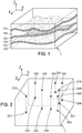
- Figure 1 represents an exemplary seismic image in a three-dimensional domain 1 associated with axes X , Y , Z .
- Such an image comprises dark regions 101, 102, 103 alternating with brighter regions 110, 120, 130.
- geophysicists may extract the tangent of the local dip p associated with every data point of the seismic image.
- the tangent of the local dip is expressed as a function of class C 1 of x, y, z coordinates.
- Iterative horizon reconstruction algorithms to solve the above equation are well-known from the existing prior art, such as for example from the above-cited article by Lomask et al.
- the invention resides in the way this Poisson equation is calculated.
- the method comprises receiving related control points 201, 202, 203, 204, 205, 206, 207, 208 in the three-dimensional domain 1.
- These related control points 201, 202, 203, 204, 205, 206, 207, 208 may for example be points that are known to belong to a given horizon because of drills realized in the ground or because of reliable geological data.
- the horizon reconstruction algorithm relies on using the x and y coordinates of the points of the three-dimensional domain 1 as input, and calculating a corresponding coordinate along axis Z to determine a reconstructed horizon.
- the method of the invention involves transformations on these points, that only affect their x and y coordinates, but do not change their z coordinate.
- reference points 210, 220, 230, 240, 250, 260, 270, 280 associated with said related control points are defined in a reference plane 10, this reference plane being defined by axes X and Y .
- the reference points 210, 220, 230, 240, 250, 260, 270, 280 have the same x and y coordinates along axes X and Y as the related control points 201, 202, 203, 204, 205, 206, 207, 208 i.e.
- the point 210 (respectively 220, 230, 240, 250, 260, 270, 280) is a projection of the related control point 201 (respectively 202, 203, 204, 205, 206, 207, 208) on a plane surface ( X , Y ).
- the invention then consists in defining pseudo-rectangles in the reference plane 10 comprising the reference points 210, 220, 230, 240, 250, 260, 270, 280 associated with related control points.
- pseudo-rectangles with random shapes map a portion of the reference plane 10.
- Each of these pseudo-rectangles contains one of the reference points 210, 220, 230, 240, 250, 260, 270, 280.
- the latter points can be located anywhere on a current pseudo-rectangle.
- reference point 280 belongs to a reference corner of a current pseudo-rectangle
- reference point 220 belongs to a current reference edge of a current pseudo-rectangle 3220.
- the pseudo-rectangles comprising reference points 210, 220, 230, 240, 250, 260, 270, 280 verify the boundary conditions called Neumann conditions, which state that for a unique point of fixed coordinates on the horizon, the derivative of the update term along the exterior normal ⁇ to the boundary is assumed to be equal to zero and its mean value fixed to zero.
- Neumann conditions state that for a unique point of fixed coordinates on the horizon, the derivative of the update term along the exterior normal ⁇ to the boundary is assumed to be equal to zero and its mean value fixed to zero.
- the following scalar product is equal to zero: ⁇ (x;y).
- ⁇ (x;y) 0.
- a plane 20 defined by axis Z and containing reference point 220 and reference corners 2220, 2210 is represented. This plane 20 comprises the current reference edge 320 of the current pseudo-rectangle 3220. On figure 3 , this plane 20 appears as a line.
- the same plane 20 is represented with the points from the seismic image having the same coordinates in the three-dimensional domain 1 as points from the plane 20, reference point 220, the related control point 202, and the reference corners 2220, 2210.
- a horizon reconstruction algorithm can be applied to points of plane 20.
- This horizon reconstruction algorithm is easier to implement since it resolves the Poisson equation in two-dimensions, that is to say, it computes a function ⁇ which can be expressed as a function of one variable and which can be graphically represented in a plane.
- the reconstructed horizon line 302 tends to follow the tangent of the dip of the points from the seismic image.
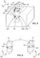
- Figure 5 represents the portion of the three-dimensional domain 1 delimited by pseudo-rectangle 3220. This portion comprises four faces: face 501 appears on the left side, face 504 on the right side, face 502 at the back and face 503 at the front of the illustration on figure 5 . Knowing a related edge 302, corresponding to a horizon line of the sought horizon, comprised in face 501, it is possible to compute the boundaries 420. The horizon line 302 can be used to compute the other horizon lines along the adjacent faces 502, 503 of the current portion of the three-dimensional domain 1 delimited by the current pseudo-rectangle 3220.
- the extremities 2201 and 2202 of the horizon line are used in two horizon reconstruction algorithms to determine a second and third horizon lines.
- the second horizon line passes through extremity 2202, comprises another extremity 2203 and is comprised in face 502.
- the third horizon line passes through extremity 2201, comprises another extremity 2204 and is comprised in face 503.
- the horizon line comprised in the remaining face 504 is determined by applying a horizon reconstruction algorithm to points of the remaining face 504, so that the horizon line passes through extremities 2203 of the second and 2204 third horizon line.
- FIG. 5 illustrates the determined boundaries 420 in the current portion ⁇ of the three-dimensional domain 1 delimited by the current pseudo-rectangle associated with related control point 202.
- the method of this invention is also efficient in the case where a single related control point is contained in the current portion ⁇ .
- Alternatives such as the configuration in which a related control point has the same x and y coordinates as a reference corner of the current pseudo-rectangle, as is the case for related control point 208, is also compatible with the invention.
- the method of the invention further proceeds by identifying, for a current pseudo-rectangle, a diffeomorphic transformation F which transforms the current pseudo-rectangle into a corresponding rectangle.
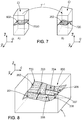
- Figure 6 illustrates a current portion ⁇ of the three-dimensional domain 1 delimited by the current pseudo-rectangle associated with related control point 202, for which the Dirichlet conditions, represented by boundaries 420, have been computed. All the points of this current portion ⁇ are transformed using diffeomorphic transformation F to obtain the corresponding rectangle and the new domain ⁇ ' delimited by the corresponding rectangle illustrated on figure 6 element B. The boundary conditions 620 in the new domain as well the transformed related control point 602 are also represented. The new domain is associated with the transformed axes X' , Y' , Z .
- the method of the invention In addition to transforming the current portion ⁇ into the new domain ⁇ ', the method of the invention also transforms the corresponding portion of the seismic image, to obtain a set of transformed points in the new domain.
- the domain on which a solution is searched corresponds to points having x and y coordinates identical to those of a rectangle, and either at least one related control point is within this new domain, or the boundary conditions of the solution are known.
- the Fourier transform is a discrete Fourier transform, and even more advantageously a fast Fourier transform. If the size of the new domain can be expressed as a number verifying 2 a 3 b 5 c 7 d 11 e 13 f , where a, b, c, d, e and f are positive integers and e+f is smaller than 1, then a particularly efficient fast Fourier transform can be implemented to further reduce the computation time of the method of the invention.
- the method comprises applying the inverse diffeomorphic transformation F -1 to the transformed part of a reconstructed horizon to obtain a part of a reconstructed horizon 720, as represented on figure 7 element B.
- the invention advantageously comprises assembling all the parts of a reconstructed horizon to obtain a reconstructed horizon on a portion of the three-dimensional domain 1 as represented on figure 8 .
- the invention may advantageously benefit from substantial optimizations that allow it to be performed faster and be easily programmed to be executed with minimal input from the user.
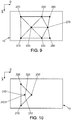
- figure 9 represents a method for defining pseudo-rectangles that have a substantially similar shape and which allows a fast and reliable calculation of the boundary conditions in each pseudo-rectangle.
- reference points 210, 220, 230, 240, 250, 260, 270, 280 associated with related control points 201, 202, 203, 204, 205, 206, 207, 208 are represented in the reference plane 10.
- a triangulation advantageously a Delaunay triangulation, connecting all these reference points to form triangles is implemented.
- the center of each side of an identified triangle is selected.
- Figure 10 represents the triangle identified by corners corresponding to reference points 210, 220 and 230.
- the reference centers 223, 212 and 213 of the sides of this triangle are also used to determine the centroid 2123 of this triangle, the centroid being the point where the median lines of the triangle cross.
- the obtained three pseudo-rectangles have substantially the same area in each triangle, and the method can systematically be implemented by a computer program.
- each triangle is lines joining two reference points having the same x and y coordinates as related control points, and boundary conditions can be easily computed in the plane comprising axis Z and comprising two related control points by using a horizon reconstruction algorithm to obtain a horizon line. Since it may occur, as seen on figure 9 , that several triangles share a common side, the calculation of boundary conditions may not have to be computed for each triangle in the portion of the three-dimensional domain 1 delimited by a triangle. Indeed the results obtained in the portion of the three-dimensional domain 1 delimited by a previously identified triangle may be reused in the portion of the three-dimensional domain 1 delimited by subsequent triangles.
- centroid 2123 shares the same x and y coordinates as a related middle point of the horizon.
- This related middle point is shared by three portions of horizon in three adjacent portions of the three-dimensional domain 1.
- Another method consists in applying a horizon reconstruction algorithm to points of the plane comprising axis Z and comprising one of the segments connecting a reference center 212, 223, 213 of a side of the triangle, and the reference centroid 2123, to obtain a horizon line.
- pseudo-rectangles it is possible to define pseudo-rectangles by combining the identified triangles two by two. Two adjacent triangles are combined by removing the segment they have in common.
- This embodiment is advantageous in that it makes it even easier to determine the boundary conditions of the portion ⁇ of the three-dimensional domain 1 delimited by a pseudo-rectangle, since every reference corner of each pseudo-rectangle is associated with a related control point.
- horizon lines passing through the related control points define the boundary conditions of each pseudo-rectangle.
- the method of the invention nonetheless also offers another major advantage over the existing prior art. Indeed, it is very efficient for computing portions of a seismic horizon when a related control point is added to or removed from a set of related control points.
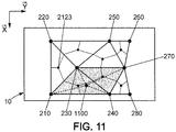
- Figure 11 represents reference plane 10 containing reference points 210, 220, 230, 240, 250, 260, 270, 280 associated with related control points 201, 202, 203, 204, 205, 206, 207, 208.
- modification information relating to the related control points is received, for example the addition of a related control point.
- the reference point 1100 in the reference plane 10 associated with the added related control point requires locally redefining pseudo-rectangles. Nevertheless, the effect is only local as shown on figure 11 , on which the darkest pseudo-rectangles correspond to the affected area that is chosen for a recalculation of the local horizon.
- adding a related control point only affects the pseudo-rectangle or pseudo-rectangles to which the added reference point associated with the added related control point belongs. Nevertheless, it is advantageous to identify an affected area by identifying the triangle or triangles to which the reference point belongs. This may enable defining new pseudo-rectangles having substantially the same size as already defined surrounding pseudo-rectangles. Since the pseudo-rectangles comprising the added reference point may share boundaries with neighboring pseudo-rectangles, two of which may belong to neighboring triangles, it is advantageous to include these neighboring triangles into the affected area and triangulate a new set of pseudo-rectangles on this affected area. On figure 11 , the area affected by the addition of reference point 1100 implies a new triangulation giving rise to twelve new pseudo-rectangles. Similar conclusions arise when a related control point is removed.
- the invention is very efficient in terms of computation time required to determine a horizon, for example when a user decides to add several related control points in a portion of the three-dimensional domain 1 which requires a finer resolution in the reconstructed horizon.
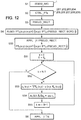
- Figure 12 is a flow-chart schematically illustrating the different steps that are implemented by the method of this invention.
- a seismic image SEISM_IMG 1 is received.
- the seismic image 1 can for example be received from a raw seismic data treatment program that outputs the data points in the three-dimensional domain 1.
- a second step S2 related control points CTRL._PTs 201, 202, 203, 204, 205, 206, 207, 208 are received.
- the x, y, z coordinates of these points are fixed and they all belong to the same horizon.
- pseudo-rectangles PSEUD._RECT. are defined, in such a way that each pseudo-rectangle is in a reference plane and comprises at least one reference point 210, 220, 230, 240, 250, 260, 270, 280.
- step S4 it is possible to apply, for each pseudo-rectangle PSEUD._RECT. one or several horizon reconstruction algorithms to points of an edge of a portion of the three-dimensional domain 1 delimited by the current pseudo-rectangle, in order to find the boundaries 420.
- step S50 a diffeomorphic transformation F is identified for each pseudo-rectangle.
- An identified diffeomorphic transformation F is applied to a current pseudo-rectangle to transform it into a corresponding rectangle.
- Step S50 also comprises applying said transformation to the points of the seismic image having the same x and y coordinates as points of the pseudo-rectangle.
- step S6 the method proceeds with step S6 by applying the inverse diffeomorphic transformation F -1 that can transform the corresponding rectangle into the current pseudo-rectangle, to the computed horizon ⁇ k .
- a comparison of the method of the invention and the global optimization method disclosed by Lomask et al. was performed on real seismic data defining a volume of 1750m by 4000m by 1600m. Complex geometries and convergent structures of the treated data resulted in an extremely noisy estimated dip, so a set of twenty seven related control points were sequentially received in critical regions corresponding for example to peaks or basins of the horizon to be reconstructed, starting from an initial set of thirteen related control points.
- each identified triangle is subdivided in three pseudo-rectangles as described above.
- the twenty seven related control points then lead to one hundred and twenty six pseudo-rectangles.
- each update term ⁇ computation through a direction descent approach required three hundred iterations and the algorithm had to be initialized with a function ⁇ 0 close to the solution. This function ⁇ 0 was obtained from a horizon reconstructed over the entire domain by assuming that only one particular related control point was known.
- Table 1 resumes the computation time in seconds that was measured using both methods. The time in parentheses corresponds to the time measured for the calculations dedicated to the Fourier transforms.
- Table 1 Size of rectangular domain (new domain) Method of the invention Method disclosed by Lomask et al. Normal size Optimal size smallest 3.3 s (1.41 s) 2.7 s (0.561 s) 79.1 s largest 9.98 s (5.47 s) 6.43 s (2.41 s) arithmetic mean 5.82 s (2.9 s) 4.26 s (1.56 s) geometric mean 5.4 s (2.54 s) 3.78 s (1.4 s)
- Table 1 shows the time required to do calculations on the portions of the three-dimensional domain 1 based on the size of the domain.
- the column labeled normal size gives the measured time that elapsed during the implementation of the method of the invention on portions of a domain that did not have a size optimized for fast Fourier transforms.
- the column labeled optimal size gives the same data but measured on portions of a domain that had a size suitable for implementing a fast Fourier transform algorithm.
- the line labeled smallest corresponds to the smallest defined portions of domains
- the line labeled largest corresponds to the largest defined portions of domains
- the arithmetic and geometric means give times calculated based on a mean value of the size of the rectangular domains. It arises from the data of table 1 that the method of the invention enables reducing the computation time by as much as thirty times when compared to global approaches like the one disclosed by Lomask et al..
- Table 2 summarizes the times in seconds measured for implementing the method of the invention when increasing the number of related control points from thirteen to twenty-seven.
- the time in parentheses corresponds to the time measured for the calculations dedicated to the Fourier transforms.
- the measured times are substantially the same, since the volume on which the computation is implemented is the entire three-dimensional domain 1.
- the method is only applied to the portion of the three-dimensional domain 1 which is affected by the addition of new related control points.
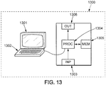
- Figure 13 is a possible embodiment for a device that enables the present invention.
- the device 1300 comprises a computer, this computer comprising a memory 1305 to store program instructions loadable into a circuit and adapted to cause circuit 1304 to carry out the steps of the present invention when the program instructions are run by the circuit 1304.
- the memory 1305 may also store data and useful information for carrying the steps of the present invention as described above.
- the circuit 1304 may be for instance:
- This computer comprises an input interface 1303 for the reception of data used for the above method according to the invention and an output interface 1306 for providing a stacked model.
- a screen 1301 and a keyboard 1302 may be provided and connected to the computer circuit 1304.
- pseudo-rectangles which are not associated with any related control point. Although doing so might seem less advantageous from a computational point of view, it may be interesting in the case in which large gaps exist between local concentrations of related control points. Defining pseudo-rectangles that are not associated with any related control point may allow mapping a continuous portion of the three-dimensional domain 1 without having a high dispersion in the size of the pseudo-rectangles. It is also possible to have pseudo-rectangles that are not associated with any related control point, but which are adjacent to other pseudo-rectangles which are. Thereby, it is possible to use the boundary conditions of the neighboring pseudo-rectangles to meet the conditions enabling a direct resolution of the Poisson equation.
- the method described above may also be implemented in a domain comprising more than three dimensions.
Claims (14)
- Verfahren zur Verbesserung wenigstens eines Abschnitts eines seismischen Horizonts aus einem seismischen Bild in einer dreidimensionalen Domäne (1), die Achsen
X ,Y ,Z , aufweist, wobei der seismische Horizont eine Funktion von Koordinaten entlang der AchsenX ,Y in der dreidimensionalen Domäne (1) ist,
wobei das Verfahren aufweist:- Empfangen (S1) des seismischen Bilds, wobei das seismische Bild Punkte hat, die zu Koordinaten entlang der AchsenX ,Y ,Z gehören;- Empfangen (S2) mehrerer verwandter Kontrollpunkte (201, 202, 203, 204, 205, 206, 207, 208), die zu Koordinaten auf den AchsenX ,Y ,Z gehören;- Definieren eines zugehörigen Referenzpunkts mit Koordinaten entlang der AchsenX , Y aus mehreren Referenzpunkten (210, 220, 230, 240, 250, 260, 270, 280) für wenigstens einen verwandten Kontrollpunkt aus den mehreren verwandten Kontrollpunkten (201, 202, 203, 204, 205, 206, 207, 208) in einer durch die AchsenX undY definierten Referenzebene (10), wobei der Referenzpunkt KoordinatenX undY hat, die identisch mit Koordinaten auf den AchsenX undY des verwandten Kontrollpunkts sind,- Definieren (S3) von Pseudorechtecken in der Referenzebene (10), wobei jedes Pseudorechteck einen Referenzpunkt aus mehreren Referenzpunkten (210, 220, 230, 240, 250, 260, 270, 280) aufweist;- für jedes aktuelle Pseudorechteck aus den definierten Pseudorechtecken:- Anwenden einer diffeomorphen Transformation F (S50) auf das aktuelle Pseudorechteck, wobei die diffeomorphe Transformation F:- eine Funktion von Koordinaten entlangX ,Y ist und eine neue Domäne definiert, die AchsenX' ,Y' ,Z' aufweist;- Punkte des seismischen Bilds mit Koordinaten entlang AchsenX ,Y , die identisch mit Koordinaten entlang der AchsenX ,Y von Punkten in dem aktuellen Pseudorechteck sind, transformiert, wobei die Punkte des seismischen Bilds den verwandten Kontrollpunkt, der zu dem aktuellen Pseudorechteck gehört, aufweisen;- das aktuelle Pseudorechteck in ein entsprechendes Rechteck transformiert;- Anwenden (S52, S53, S54, S55) eines Horizont-Rekonstruktionsalgorithmus auf die transformierten Punkte, um einen Teil eines transformierten Horizonts (7020) zu bestimmen, wobei dieser Teil eines transformierten Horizonts (7020) den transformierten verwandten Kontrollpunkt (602) aufweist, wobei die Rekonstruktion des seismischen Horizonts das Lösen (S54) der Poisson-Gleichung Δ(δτ) = -div(r) aufweist, wobei δτ eine unbekannte Funktion von Koordinaten entlang der AchsenX ,Y ist, Δ den Laplace-Operator in der neuen Domäne bezeichnet, div den Divergenzvektoroperator in der neuen Domäne bezeichnet und r eine feste Funktion von Koordinaten entlang der AchsenX' ,Y' ist;- Berechnen eines Teils des Horizonts (720), wobei das Berechnen eines Teils des Horizonts (720) das Anwenden (S6) einer inversen diffeomorphen Transformation der diffeomorphen Transformation F-1 auf den bestimmten Teil eines transformierten Horizonts (7020) aufweist. - Verfahren nach Anspruch 1, wobei das Pseudorechteck derart definiert wird, dass der Referenzpunkt (220), der in einem Pseudorechteck (3220) enthalten ist, zu einem aktuellen Referenzrand (320) des Pseudorechtecks (3220) gehört.
- Verfahren nach Anspruch 1, wobei das Verfahren vor dem Anwenden einer diffeomorphen Transformation F (S50) das Anwenden eines Horizont-Rekonstruktionsalgorithmus auf Randpunkte mit Koordinatenachsen
X, Y, die identisch mit Koordinaten entlang der AchsenX, Y von Referenzrandpunkten des aktuellen Referenzrands sind, für jedes aktuelle Pseudorechteck (3220) aufweist, das einen Referenzpunkt (220), der zu einem aktuellen Referenzrand (320) des Pseudorechtecks (3220) von den definierten Pseudorechtecken gehört, aufweist. - Verfahren nach einem der vorhergehenden Ansprüche, wobei wenigstens eine Referenzecke jedes Pseudorechtecks aus den definierten Pseudorechtecken Koordinaten entlang der Achsen
X, Y hat, die identisch mit Koordinaten entlang der AchsenX ,Y eines verwandten Kontrollpunkts aus den mehreren verwandten Kontrollpunkten (201, 202, 203, 204, 205, 206, 207, 208) sind. - Verfahren nach einem der vorhergehenden Ansprüche, wobei die empfangenen mehreren verwandten Kontrollpunkte (201, 202, 203, 204, 205, 206, 207, 208) wenigstens drei verwandte Kontrollpunkte (201, 202, 203) aufweisen, und wobei das Definieren von Pseudorechtecken aufweist:- Identifizieren von Referenzpunkten in einer Referenzebene (10);- Identifizieren von Dreiecken mit einer ersten Referenzecke (210), einer zweiten Referenzecke (220) und einer dritten Referenzecke (230) aus den identifizierten Referenzpunkten (210, 220, 230, 240, 250, 260, 270, 280) unter Verwendung einer Triangulation, und- in jedem der identifizierten Dreiecke:wobei ein Pseudorechteck durch Segmente definiert wird, welche die erste Referenzecke (210) mit dem ersten Referenzzentrum (212), das erste Referenzzentrum (212) mit dem Referenzschwerpunkt (2123), den Referenzschwerpunkt (2123) mit dem zweiten Referenzzentrum (213) und das zweite Referenzzentrum (213) mit der ersten Referenzecke (210) verbinden.- Identifizieren eines Referenzschwerpunkts (2123) des Dreiecks,- Identifizieren eines ersten Referenzzentrums (212) des Segments, das durch die erste Referenzecke (210) und die zweite Referenzecke (220) definiert wird;- Identifizieren eines zweiten Referenzzentrums (213) des Segments, das durch die erste Referenzecke (210) und die dritte Referenzecke (230) definiert wird;
- Verfahren nach Anspruch 5, wobei das Verfahren vor dem Anwenden einer diffeomorphen Transformation F (S50) für ein identifiziertes Dreieck aufweist:- Identifizieren eines ersten (201), zweiten (202) und dritten (203) verwandten Kontrollpunkts aus den mehreren verwandten Kontrollpunkten, die zu entsprechenden ersten (210), zweiten (220) und dritten (230) Referenzecken des identifizierten Dreiecks gehören;- Anwenden eines Horizont-Rekonstruktionsalgorithmus auf Punkte einer Ebene, die eine Achse
Z aufweist und die ersten (201) und zweiten (202) verwandten Kontrollpunkte aufweist, um einen ersten Abschnitt eines ersten lokalen Horizonts zu bestimmen;- Identifizieren eines ersten verwandten Mittelpunkts auf dem ersten Abschnitt des ersten lokalen Horizonts mit Koordinaten entlang AchsenX undY , die identisch mit Koordinaten entlang AchsenX undY des ersten Referenzzentrums (212) sind;- Anwenden eines Horizont-Rekonstruktionsalgorithmus auf eine Ebene, welche die AchseZ aufweist, und die ersten (201) und dritten (203) verwandten Kontrollpunkte aufweist, um einen zweiten Abschnitt eines zweiten lokalen Horizonts zu bestimmen;- Identifizieren eines zweiten verwandten Mittelpunkts auf dem zweiten Abschnitt des zweiten lokalen Horizonts mit Koordinaten entlang AchsenX undY , die identisch mit Koordinaten entlang AchsenX undY des zweiten Referenzzentrums (213) sind;- Berechnen einer Koordinate entlang der AchseZ eines verwandten Mittelpunkts mit Koordinaten entlang der AchsenX undY , die identisch mit Koordinaten entlang der AchsenX undY des Referenzschwerpunkts (2123) des identifizierten Dreiecks sind, wobei die Berechnung der Koordinate entlang der AchseZ eine Funktion der Koordinaten eines Punkts auf den bestimmten ersten oder zweiten lokalen Horizonten ist. - Verfahren nach Anspruch 6, wobei das Berechnen einer Koordinate entlang der Achse
Z eines verwandten Mittelpunkts des identifizierten Dreiecks erreicht wird, indem ein Horizont-Rekonstruktionsalgorithmus auf Punkte einer Ebene angewendet wird, welche die AchseZ aufweist und das Segment, welches das erste (212) Referenzzentrum mit dem Referenzschwerpunkt verbindet, oder das Segment, welches das zweite (213) Referenzzentrum mit dem Referenzschwerpunkt (2123) verbindet, aufweist. - Verfahren nach Anspruch 6, wobei das Berechnen einer Koordinate entlang der Achse
Z des verwandten Mittelpunkts erreicht wird, indem der Mittelwert der Koordinaten entlang der AchseZ des ersten (212) und zweiten (213) verwandten Referenzzentrums erreicht wird. - Verfahren nach einem der vorhergehenden Ansprüche, wobei die Poisson-Gleichung unter Verwendung eines Fouriertransformationsalgorithmus gelöst wird (S54).
- Verfahren nach einem der vorhergehenden Ansprüche, wobei die definierten Pseudorechtecke einen zusammenhängenden Abschnitt der Referenzebene (10) abbilden.
- Verfahren nach einem der vorhergehenden Ansprüche, wobei das Verfahren ferner das Berechnen eines Abschnitts eines seismischen Horizonts (800) wenigstens aus dem berechneten Teil des Horizonts (720) jedes aktuellen Pseudorechtecks aus den definierten Pseudorechtecken aufweist.
- Verfahren nach einem der Ansprüche 5 bis 8 und einem der Ansprüche 9 bis 10, wobei das Verfahren ferner das Berechnen eines Abschnitts eines seismischen Horizonts (800) wenigstens aus dem berechneten Teil des Horizonts (720) jedes aktuellen Pseudorechtecks aus den definierten Pseudorechtecken aufweist, und wobei das Verfahren nach dem Berechnen eines Abschnitts eines seismischen Horizonts (800) aufweist:- Empfangen von Modifikationsinformationen, welche die verwandten Kontrollpunkte betreffen;- Identifizieren von Pseudorechtecken, die von den empfangenen Modifikationsinformationen, welche die verwandten Kontrollpunkte betreffen, beeinflusst werden;- Definieren eines neuen Satzes von Pseudorechtecken in einem lokalen Bereich, der dem Bereich entspricht, der von den Pseudorechtecken belegt wird, die von den empfangenen Modifikationsinformationen, welche die verwandten Kontrollpunkte betreffen, betroffen sind;- für jedes aktuelle Pseudorechteck aus dem neuen Satz von Pseudorechtecken:- Anwenden einer diffeomorphen Transformation F (S50) auf das aktuelle Pseudorechteck, wobei die diffeomorphe Transformation F:- eine Funktion von Koordinaten entlang
X ,Y ist und eine neue Domäne definiert, die AchsenX' ,Y' ,Z' , aufweist;- Punkte des seismischen Bilds mit Koordinaten entlang AchsenX ,Y , die identisch mit Koordinaten entlang der AchsenX ,Y von Punkten in dem aktuellen Pseudorechteck sind, transformiert, wobei die Punkte des seismischen Bilds den verwandten Kontrollpunkt, der zu dem aktuellen Pseudorechteck gehört, umfassen;- das aktuelle Pseudorechteck in ein entsprechendes Rechteck transformiert;- Anwenden (S52, S53, S54, S55) eines Horizont-Rekonstruktionsalgorithmus auf die transformierten Punkte, um einen Teil eines transformierten Horizonts (7020) zu bestimmen, wobei dieser Teil eines transformierten Horizonts (7020) den transformierten verwandten Kontrollpunkt (602) aufweist, wobei die Rekonstruktion des seismischen Horizonts das Lösen (S54) der Poisson-Gleichung Δ(δτ) = -div(r) aufweist, wobei δτ eine unbekannte Funktion von Koordinaten entlang der AchsenX ,Y ist, Δ den Laplace-Operator in der neuen Domäne bezeichnet, div den Divergenzvektoroperator in der neuen Domäne bezeichnet und r eine feste Funktion von Koordinaten entlang der AchsenX' ,Y' ist;- Berechnen eines Teils des Horizonts (720), wobei das Berechnen eines Teils des Horizonts (720) das Anwenden (S6) einer inversen diffeomorphen Transformation der diffeomorphen Transformation F-1 auf den bestimmten Teil eines transformierten Horizonts (7020) aufweist. - Vorrichtung (13) zur Verbesserung der Bestimmung wenigstens eines Abschnitts eines seismischen Horizonts aus einem seismischen Bild in einer dreidimensionalen Domäne (1), die Achsen
X ,Y ,Z aufweist, wobei der seismische Horizont eine Funktion von Koordinaten entlang der AchsenX ,Y in der dreidimensionalen Domäne (1) ist,
wobei die Vorrichtung (1300) aufweist:- eine Eingabeschnittstelle (1303) zum Empfangen (S1) des seismischen Bilds, wobei das seismische Bild Punkte hat, die zu Koordinaten entlang der AchsenX ,Y ,Z gehören; und zum Empfangen (S2) mehrerer zugehöriger Kontrollpunkte (201, 202, 203, 204, 205, 206, 207, 208), die zu Koordinaten auf den AchsenX ,Y ,Z gehören;- eine Schaltung (1304) zum Definieren eines zugehörigen Referenzpunkts mit Koordinaten entlang der AchsenX ,Y aus mehreren Referenzpunkten (210, 220, 230, 240, 250, 260, 270, 280) für wenigstens einen verwandten Kontrollpunkt aus den mehreren verwandten Kontrollpunkten (201, 202, 203, 204, 205, 206, 207, 208) in einer durch die AchsenX undY definierten Referenzebene (10), wobei der Referenzpunkt KoordinatenX undY hat, die identisch mit Koordinaten auf den AchsenX undY des verwandten Kontrollpunkts sind,- eine Schaltung (1304) zum Definieren von Pseudorechtecken in der Referenzebene (10), wobei jedes Pseudorechteck einen Referenzpunkt aus mehreren Referenzpunkten (210, 220, 230, 240, 250, 260, 270, 280) aufweist;- eine Schaltung (1304), die eingerichtet ist, um für jedes aktuelle Pseudorechteck aus den definierten Pseudorechtecken:- eine diffeomorphe Transformation F (S50) auf das aktuelle Pseudorechteck anzuwenden, wobei die diffeomorphe Transformation F:- eine Funktion von Koordinaten entlangX ,Y ist und eine neue Domäne definiert, die AchsenX ',Y ',Z ' aufweist;- Punkte des seismischen Bilds mit Koordinaten entlang AchsenX ,Y , die identisch mit Koordinaten entlang der AchsenX ,Y von Punkten in dem aktuellen Pseudorechteck sind, transformiert, wobei die Punkte des seismischen Bilds den verwandten Kontrollpunkt, der zu dem aktuellen Pseudorechteck gehört, umfassen;- das aktuelle Pseudorechteck in ein entsprechendes Rechteck transformiert;- einen Horizont-Rekonstruktionsalgorithmus auf die transformierten Punkte anzuwenden (S52, S53, S54, S55), um einen Teil eines transformierten Horizonts (7020) zu bestimmen, wobei dieser Teil eines transformierten Horizonts (7020) den transformierten verwandten Kontrollpunkt (602) aufweist, wobei die Rekonstruktion des seismischen Horizonts das Lösen (S54) der Poisson-Gleichung Δ(δτ) = -div(r) aufweist, wobei δτ eine unbekannte Funktion von Koordinaten entlang der AchsenX ,Y ist, Δ den Laplace-Operator in der neuen Domäne bezeichnet, div den Divergenzvektoroperator in der neuen Domäne bezeichnet und r eine feste Funktion von Koordinaten entlang der AchsenX' ,Y' ist;- einen Teil des Horizonts (720) zu berechnen, wobei das Berechnen eines Teils des Horizonts (720) das Anwenden (S6) einer inversen diffeomorphen Transformation der diffeomorphen Transformation F-1 auf den bestimmten Teil eines transformierten Horizonts (7020) aufweist. - Dauerhaftes computerlesbares Speichermedium, das ein Computerprogramm darauf gespeichert hat, das Programmanweisungen aufweist, wobei das Computerprogramm in eine Datenverarbeitungseinheit ladbar ist und geeignet ist, um zu bewirken, dass die Datenverarbeitungseinheit die Schritte nach einem der Ansprüche 1 bis 12 ausführt, wenn das Computerprogramm von der Datenverarbeitungsvorrichtung laufen gelassen wird.
Applications Claiming Priority (2)
| Application Number | Priority Date | Filing Date | Title |
|---|---|---|---|
| US201261681005P | 2012-08-08 | 2012-08-08 | |
| PCT/EP2013/066492 WO2014023737A2 (en) | 2012-08-08 | 2013-08-06 | Method for enhancing the determination of a seismic horizon |
Publications (2)
| Publication Number | Publication Date |
|---|---|
| EP2883087A2 EP2883087A2 (de) | 2015-06-17 |
| EP2883087B1 true EP2883087B1 (de) | 2021-06-23 |
Family
ID=48916099
Family Applications (1)
| Application Number | Title | Priority Date | Filing Date |
|---|---|---|---|
| EP13745135.7A Active EP2883087B1 (de) | 2012-08-08 | 2013-08-06 | Verfahren zur verbesserung der bestimmung eines seismischen horizonts |
Country Status (5)
| Country | Link |
|---|---|
| US (1) | US9214041B2 (de) |
| EP (1) | EP2883087B1 (de) |
| JP (1) | JP6019230B2 (de) |
| SA (1) | SA515360008B1 (de) |
| WO (1) | WO2014023737A2 (de) |
Families Citing this family (5)
| Publication number | Priority date | Publication date | Assignee | Title |
|---|---|---|---|---|
| WO2014083402A2 (en) * | 2012-11-08 | 2014-06-05 | Total Sa | Method and device to process a three dimensional seismic image |
| NO342146B1 (en) * | 2016-05-18 | 2018-04-03 | Roxar Software Solutions As | Method of constructing a geologic model |
| US10571585B2 (en) * | 2016-08-31 | 2020-02-25 | Chevron U.S.A. Inc. | System and method for time-lapsing seismic imaging |
| US10914852B2 (en) | 2017-03-16 | 2021-02-09 | International Business Machines Corporation | Unsupervised identification of seismic horizons using swarms of cooperating agents |
| CN111796324B (zh) * | 2019-04-09 | 2023-02-10 | 中国石油天然气股份有限公司 | 地震全层位追踪方法及装置 |
Family Cites Families (10)
| Publication number | Priority date | Publication date | Assignee | Title |
|---|---|---|---|---|
| FR2652180B1 (fr) * | 1989-09-20 | 1991-12-27 | Mallet Jean Laurent | Procede de modelisation d'une surface et dispositif pour sa mise en óoeuvre. |
| US6615158B2 (en) * | 2001-06-25 | 2003-09-02 | National Instruments Corporation | System and method for analyzing a surface by mapping sample points onto the surface and sampling the surface at the mapped points |
| US7127100B2 (en) * | 2001-06-25 | 2006-10-24 | National Instruments Corporation | System and method for analyzing an image |
| FR2869693B1 (fr) | 2004-04-30 | 2006-06-02 | Total France Sa | Procede et programme de propagation d'un marqueur sismique dans un ensemble de traces sismiques |
| US20060047429A1 (en) * | 2004-08-24 | 2006-03-02 | Adams Steven L | Method of estimating geological formation depths by converting interpreted seismic horizons from the time domain to the depth domain |
| FR2923312B1 (fr) * | 2007-11-06 | 2009-12-18 | Total Sa | Procede de traitement d'images sismiques du sous-sol |
| EA026356B1 (ru) * | 2008-05-22 | 2017-03-31 | Эксонмобил Апстрим Рисерч Компани | Способ (варианты) и машиночитаемый носитель для сейсмического исследования глубинной зоны |
| EP2409176B1 (de) * | 2009-04-16 | 2021-03-03 | Landmark Graphics Corporation | Systeme und verfahren zur seismischen bildgebung, die eine schnelle zielorientierte beleuchtungsberechnung verwenden |
| US8694262B2 (en) * | 2011-08-15 | 2014-04-08 | Chevron U.S.A. Inc. | System and method for subsurface characterization including uncertainty estimation |
| FR2980854A1 (fr) | 2011-10-04 | 2013-04-05 | Total Sa | Procede de pointage d'horizons sismiques discontinus dans des images sismiques. |
-
2013
- 2013-08-06 US US14/420,267 patent/US9214041B2/en active Active
- 2013-08-06 JP JP2015525866A patent/JP6019230B2/ja not_active Expired - Fee Related
- 2013-08-06 WO PCT/EP2013/066492 patent/WO2014023737A2/en active Application Filing
- 2013-08-06 EP EP13745135.7A patent/EP2883087B1/de active Active
-
2015
- 2015-02-05 SA SA515360008A patent/SA515360008B1/ar unknown
Also Published As
| Publication number | Publication date |
|---|---|
| US9214041B2 (en) | 2015-12-15 |
| JP6019230B2 (ja) | 2016-11-02 |
| SA515360008B1 (ar) | 2016-03-27 |
| WO2014023737A3 (en) | 2014-05-01 |
| JP2015529814A (ja) | 2015-10-08 |
| US20150199845A1 (en) | 2015-07-16 |
| WO2014023737A2 (en) | 2014-02-13 |
| EP2883087A2 (de) | 2015-06-17 |
Similar Documents
| Publication | Publication Date | Title |
|---|---|---|
| EP2883087B1 (de) | Verfahren zur verbesserung der bestimmung eines seismischen horizonts | |
| Béréziat et al. | Solving ill-posed image processing problems using data assimilation | |
| Riyanti et al. | A new iterative solver for the time-harmonic wave equation | |
| CN107407736B (zh) | 生成无多次波的数据集的多阶段全波场反演处理 | |
| US9341729B2 (en) | Amplitude contrast seismic attribute | |
| WO2009126951A2 (en) | Visulation of geologic features using data representations thereof | |
| Luo et al. | Higher-order schemes for 3D first-arrival traveltimes and amplitudes | |
| Merland et al. | Voronoi grids conforming to 3D structural features | |
| Zinck et al. | Fast seismic horizon reconstruction based on local dip transformation | |
| Desquilbet et al. | Single pass computation of first seismic wave travel time in three dimensional heterogeneous media with general anisotropy | |
| Bekar et al. | Solving the eikonal equation for compressional and shear waves in anisotropic media using peridynamic differential operator | |
| EP2631678A2 (de) | Funktionserkennung in seismischen Volumen | |
| Motta et al. | A 3D sketch-based formulation to model salt bodies from seismic data | |
| EP3259618B1 (de) | Grenzbedingungen eines schwarzen lochs | |
| US11965999B2 (en) | Method and system for processing seismic images to obtain seismic horizon surfaces for a geological formation | |
| GB2468023A (en) | Seismic attributes for structural analysis | |
| Copeland* et al. | Fracture surface extraction and stress field estimation from three-dimensional microseismic data | |
| OA17254A (en) | Method for enhancing the determination of a seismic horizon. | |
| Hjelle et al. | A numerical framework for modeling folds in structural geology | |
| Jain et al. | A comparative study of iterative solvers for image de-noising | |
| Doghraji et al. | Seismic horizon reconstruction on polygonal domains using the Schwarz-Christoffel transformation | |
| Zinck et al. | Local dip transformation for fast seismic horizon reconstruction | |
| Holicki et al. | Acoustic directional snapshot wavefield decomposition | |
| Antunes et al. | Stereo estimation of depth along virtual cut planes | |
| Doghraji et al. | Free-shaped polygonal seismic horizon reconstruction using space transformations |
Legal Events
| Date | Code | Title | Description |
|---|---|---|---|
| PUAI | Public reference made under article 153(3) epc to a published international application that has entered the european phase |
Free format text: ORIGINAL CODE: 0009012 |
|
| 17P | Request for examination filed |
Effective date: 20150211 |
|
| AK | Designated contracting states |
Kind code of ref document: A2 Designated state(s): AL AT BE BG CH CY CZ DE DK EE ES FI FR GB GR HR HU IE IS IT LI LT LU LV MC MK MT NL NO PL PT RO RS SE SI SK SM TR |
|
| AX | Request for extension of the european patent |
Extension state: BA ME |
|
| DAX | Request for extension of the european patent (deleted) | ||
| RAP1 | Party data changed (applicant data changed or rights of an application transferred) |
Owner name: UNIVERSITE DE BORDEAUX Owner name: ECOLE NATIONALE SUPERIEURE DES SCIENCES AGRONOMIQUES DE BORDEAUX-AQUITAINE Owner name: INSTITUT POLYTECHNIQUE DE BORDEAUX Owner name: CENTRE NATIONAL DE LA RECHERCHE SCIENTIFIQUE (C.N.R.S.) Owner name: TOTAL SE |
|
| GRAP | Despatch of communication of intention to grant a patent |
Free format text: ORIGINAL CODE: EPIDOSNIGR1 |
|
| STAA | Information on the status of an ep patent application or granted ep patent |
Free format text: STATUS: GRANT OF PATENT IS INTENDED |
|
| INTG | Intention to grant announced |
Effective date: 20210120 |
|
| GRAS | Grant fee paid |
Free format text: ORIGINAL CODE: EPIDOSNIGR3 |
|
| GRAA | (expected) grant |
Free format text: ORIGINAL CODE: 0009210 |
|
| STAA | Information on the status of an ep patent application or granted ep patent |
Free format text: STATUS: THE PATENT HAS BEEN GRANTED |
|
| AK | Designated contracting states |
Kind code of ref document: B1 Designated state(s): AL AT BE BG CH CY CZ DE DK EE ES FI FR GB GR HR HU IE IS IT LI LT LU LV MC MK MT NL NO PL PT RO RS SE SI SK SM TR |
|
| REG | Reference to a national code |
Ref country code: GB Ref legal event code: FG4D |
|
| REG | Reference to a national code |
Ref country code: CH Ref legal event code: EP |
|
| REG | Reference to a national code |
Ref country code: AT Ref legal event code: REF Ref document number: 1404772 Country of ref document: AT Kind code of ref document: T Effective date: 20210715 Ref country code: DE Ref legal event code: R096 Ref document number: 602013078059 Country of ref document: DE |
|
| REG | Reference to a national code |
Ref country code: IE Ref legal event code: FG4D |
|
| REG | Reference to a national code |
Ref country code: NL Ref legal event code: FP |
|
| REG | Reference to a national code |
Ref country code: LT Ref legal event code: MG9D |
|
| REG | Reference to a national code |
Ref country code: NO Ref legal event code: T2 Effective date: 20210623 |
|
| PG25 | Lapsed in a contracting state [announced via postgrant information from national office to epo] |
Ref country code: HR Free format text: LAPSE BECAUSE OF FAILURE TO SUBMIT A TRANSLATION OF THE DESCRIPTION OR TO PAY THE FEE WITHIN THE PRESCRIBED TIME-LIMIT Effective date: 20210623 Ref country code: BG Free format text: LAPSE BECAUSE OF FAILURE TO SUBMIT A TRANSLATION OF THE DESCRIPTION OR TO PAY THE FEE WITHIN THE PRESCRIBED TIME-LIMIT Effective date: 20210923 Ref country code: FI Free format text: LAPSE BECAUSE OF FAILURE TO SUBMIT A TRANSLATION OF THE DESCRIPTION OR TO PAY THE FEE WITHIN THE PRESCRIBED TIME-LIMIT Effective date: 20210623 Ref country code: LT Free format text: LAPSE BECAUSE OF FAILURE TO SUBMIT A TRANSLATION OF THE DESCRIPTION OR TO PAY THE FEE WITHIN THE PRESCRIBED TIME-LIMIT Effective date: 20210623 |
|
| REG | Reference to a national code |
Ref country code: AT Ref legal event code: MK05 Ref document number: 1404772 Country of ref document: AT Kind code of ref document: T Effective date: 20210623 |
|
| PG25 | Lapsed in a contracting state [announced via postgrant information from national office to epo] |
Ref country code: LV Free format text: LAPSE BECAUSE OF FAILURE TO SUBMIT A TRANSLATION OF THE DESCRIPTION OR TO PAY THE FEE WITHIN THE PRESCRIBED TIME-LIMIT Effective date: 20210623 Ref country code: GR Free format text: LAPSE BECAUSE OF FAILURE TO SUBMIT A TRANSLATION OF THE DESCRIPTION OR TO PAY THE FEE WITHIN THE PRESCRIBED TIME-LIMIT Effective date: 20210924 Ref country code: SE Free format text: LAPSE BECAUSE OF FAILURE TO SUBMIT A TRANSLATION OF THE DESCRIPTION OR TO PAY THE FEE WITHIN THE PRESCRIBED TIME-LIMIT Effective date: 20210623 Ref country code: RS Free format text: LAPSE BECAUSE OF FAILURE TO SUBMIT A TRANSLATION OF THE DESCRIPTION OR TO PAY THE FEE WITHIN THE PRESCRIBED TIME-LIMIT Effective date: 20210623 |
|
| PG25 | Lapsed in a contracting state [announced via postgrant information from national office to epo] |
Ref country code: SM Free format text: LAPSE BECAUSE OF FAILURE TO SUBMIT A TRANSLATION OF THE DESCRIPTION OR TO PAY THE FEE WITHIN THE PRESCRIBED TIME-LIMIT Effective date: 20210623 Ref country code: SK Free format text: LAPSE BECAUSE OF FAILURE TO SUBMIT A TRANSLATION OF THE DESCRIPTION OR TO PAY THE FEE WITHIN THE PRESCRIBED TIME-LIMIT Effective date: 20210623 Ref country code: CZ Free format text: LAPSE BECAUSE OF FAILURE TO SUBMIT A TRANSLATION OF THE DESCRIPTION OR TO PAY THE FEE WITHIN THE PRESCRIBED TIME-LIMIT Effective date: 20210623 Ref country code: EE Free format text: LAPSE BECAUSE OF FAILURE TO SUBMIT A TRANSLATION OF THE DESCRIPTION OR TO PAY THE FEE WITHIN THE PRESCRIBED TIME-LIMIT Effective date: 20210623 Ref country code: RO Free format text: LAPSE BECAUSE OF FAILURE TO SUBMIT A TRANSLATION OF THE DESCRIPTION OR TO PAY THE FEE WITHIN THE PRESCRIBED TIME-LIMIT Effective date: 20210623 Ref country code: PT Free format text: LAPSE BECAUSE OF FAILURE TO SUBMIT A TRANSLATION OF THE DESCRIPTION OR TO PAY THE FEE WITHIN THE PRESCRIBED TIME-LIMIT Effective date: 20211025 Ref country code: ES Free format text: LAPSE BECAUSE OF FAILURE TO SUBMIT A TRANSLATION OF THE DESCRIPTION OR TO PAY THE FEE WITHIN THE PRESCRIBED TIME-LIMIT Effective date: 20210623 Ref country code: AT Free format text: LAPSE BECAUSE OF FAILURE TO SUBMIT A TRANSLATION OF THE DESCRIPTION OR TO PAY THE FEE WITHIN THE PRESCRIBED TIME-LIMIT Effective date: 20210623 |
|
| PG25 | Lapsed in a contracting state [announced via postgrant information from national office to epo] |
Ref country code: PL Free format text: LAPSE BECAUSE OF FAILURE TO SUBMIT A TRANSLATION OF THE DESCRIPTION OR TO PAY THE FEE WITHIN THE PRESCRIBED TIME-LIMIT Effective date: 20210623 |
|
| REG | Reference to a national code |
Ref country code: DE Ref legal event code: R119 Ref document number: 602013078059 Country of ref document: DE |
|
| REG | Reference to a national code |
Ref country code: CH Ref legal event code: PL |
|
| PG25 | Lapsed in a contracting state [announced via postgrant information from national office to epo] |
Ref country code: MC Free format text: LAPSE BECAUSE OF FAILURE TO SUBMIT A TRANSLATION OF THE DESCRIPTION OR TO PAY THE FEE WITHIN THE PRESCRIBED TIME-LIMIT Effective date: 20210623 |
|
| REG | Reference to a national code |
Ref country code: BE Ref legal event code: MM Effective date: 20210831 |
|
| PG25 | Lapsed in a contracting state [announced via postgrant information from national office to epo] |
Ref country code: LI Free format text: LAPSE BECAUSE OF NON-PAYMENT OF DUE FEES Effective date: 20210831 Ref country code: DK Free format text: LAPSE BECAUSE OF FAILURE TO SUBMIT A TRANSLATION OF THE DESCRIPTION OR TO PAY THE FEE WITHIN THE PRESCRIBED TIME-LIMIT Effective date: 20210623 Ref country code: CH Free format text: LAPSE BECAUSE OF NON-PAYMENT OF DUE FEES Effective date: 20210831 |
|
| PLBE | No opposition filed within time limit |
Free format text: ORIGINAL CODE: 0009261 |
|
| STAA | Information on the status of an ep patent application or granted ep patent |
Free format text: STATUS: NO OPPOSITION FILED WITHIN TIME LIMIT |
|
| 26N | No opposition filed |
Effective date: 20220324 |
|
| PG25 | Lapsed in a contracting state [announced via postgrant information from national office to epo] |
Ref country code: LU Free format text: LAPSE BECAUSE OF NON-PAYMENT OF DUE FEES Effective date: 20210806 Ref country code: AL Free format text: LAPSE BECAUSE OF FAILURE TO SUBMIT A TRANSLATION OF THE DESCRIPTION OR TO PAY THE FEE WITHIN THE PRESCRIBED TIME-LIMIT Effective date: 20210623 |
|
| PG25 | Lapsed in a contracting state [announced via postgrant information from national office to epo] |
Ref country code: IT Free format text: LAPSE BECAUSE OF FAILURE TO SUBMIT A TRANSLATION OF THE DESCRIPTION OR TO PAY THE FEE WITHIN THE PRESCRIBED TIME-LIMIT Effective date: 20210623 Ref country code: IE Free format text: LAPSE BECAUSE OF NON-PAYMENT OF DUE FEES Effective date: 20210806 Ref country code: DE Free format text: LAPSE BECAUSE OF NON-PAYMENT OF DUE FEES Effective date: 20220301 Ref country code: BE Free format text: LAPSE BECAUSE OF NON-PAYMENT OF DUE FEES Effective date: 20210831 |
|
| PG25 | Lapsed in a contracting state [announced via postgrant information from national office to epo] |
Ref country code: HU Free format text: LAPSE BECAUSE OF FAILURE TO SUBMIT A TRANSLATION OF THE DESCRIPTION OR TO PAY THE FEE WITHIN THE PRESCRIBED TIME-LIMIT; INVALID AB INITIO Effective date: 20130806 |
|
| PG25 | Lapsed in a contracting state [announced via postgrant information from national office to epo] |
Ref country code: CY Free format text: LAPSE BECAUSE OF FAILURE TO SUBMIT A TRANSLATION OF THE DESCRIPTION OR TO PAY THE FEE WITHIN THE PRESCRIBED TIME-LIMIT Effective date: 20210623 |
|
| PGFP | Annual fee paid to national office [announced via postgrant information from national office to epo] |
Ref country code: NL Payment date: 20230821 Year of fee payment: 11 |
|
| PGFP | Annual fee paid to national office [announced via postgrant information from national office to epo] |
Ref country code: NO Payment date: 20230824 Year of fee payment: 11 Ref country code: GB Payment date: 20230822 Year of fee payment: 11 |
|
| PGFP | Annual fee paid to national office [announced via postgrant information from national office to epo] |
Ref country code: FR Payment date: 20230824 Year of fee payment: 11 |