EP2882939B1 - Verfahren zur aufbereitung einer gasturbinenschaufel sowie verwendung einer gasturbine mit derartiger schaufel - Google Patents
Verfahren zur aufbereitung einer gasturbinenschaufel sowie verwendung einer gasturbine mit derartiger schaufel Download PDFInfo
- Publication number
- EP2882939B1 EP2882939B1 EP12772752.7A EP12772752A EP2882939B1 EP 2882939 B1 EP2882939 B1 EP 2882939B1 EP 12772752 A EP12772752 A EP 12772752A EP 2882939 B1 EP2882939 B1 EP 2882939B1
- Authority
- EP
- European Patent Office
- Prior art keywords
- thermal barrier
- barrier coating
- layer
- ceramic
- vanes
- Prior art date
- Legal status (The legal status is an assumption and is not a legal conclusion. Google has not performed a legal analysis and makes no representation as to the accuracy of the status listed.)
- Revoked
Links
Images

Classifications
-
- F—MECHANICAL ENGINEERING; LIGHTING; HEATING; WEAPONS; BLASTING
- F01—MACHINES OR ENGINES IN GENERAL; ENGINE PLANTS IN GENERAL; STEAM ENGINES
- F01D—NON-POSITIVE DISPLACEMENT MACHINES OR ENGINES, e.g. STEAM TURBINES
- F01D5/00—Blades; Blade-carrying members; Heating, heat-insulating, cooling or antivibration means on the blades or the members
- F01D5/12—Blades
- F01D5/28—Selecting particular materials; Particular measures relating thereto; Measures against erosion or corrosion
- F01D5/288—Protective coatings for blades
-
- B—PERFORMING OPERATIONS; TRANSPORTING
- B05—SPRAYING OR ATOMISING IN GENERAL; APPLYING FLUENT MATERIALS TO SURFACES, IN GENERAL
- B05D—PROCESSES FOR APPLYING FLUENT MATERIALS TO SURFACES, IN GENERAL
- B05D1/00—Processes for applying liquids or other fluent materials
- B05D1/02—Processes for applying liquids or other fluent materials performed by spraying
-
- B—PERFORMING OPERATIONS; TRANSPORTING
- B05—SPRAYING OR ATOMISING IN GENERAL; APPLYING FLUENT MATERIALS TO SURFACES, IN GENERAL
- B05D—PROCESSES FOR APPLYING FLUENT MATERIALS TO SURFACES, IN GENERAL
- B05D7/00—Processes, other than flocking, specially adapted for applying liquids or other fluent materials to particular surfaces or for applying particular liquids or other fluent materials
- B05D7/50—Multilayers
-
- B—PERFORMING OPERATIONS; TRANSPORTING
- B23—MACHINE TOOLS; METAL-WORKING NOT OTHERWISE PROVIDED FOR
- B23P—METAL-WORKING NOT OTHERWISE PROVIDED FOR; COMBINED OPERATIONS; UNIVERSAL MACHINE TOOLS
- B23P6/00—Restoring or reconditioning objects
- B23P6/002—Repairing turbine components, e.g. moving or stationary blades, rotors
- B23P6/005—Repairing turbine components, e.g. moving or stationary blades, rotors using only replacement pieces of a particular form
-
- F—MECHANICAL ENGINEERING; LIGHTING; HEATING; WEAPONS; BLASTING
- F01—MACHINES OR ENGINES IN GENERAL; ENGINE PLANTS IN GENERAL; STEAM ENGINES
- F01D—NON-POSITIVE DISPLACEMENT MACHINES OR ENGINES, e.g. STEAM TURBINES
- F01D5/00—Blades; Blade-carrying members; Heating, heat-insulating, cooling or antivibration means on the blades or the members
- F01D5/005—Repairing methods or devices
-
- F—MECHANICAL ENGINEERING; LIGHTING; HEATING; WEAPONS; BLASTING
- F05—INDEXING SCHEMES RELATING TO ENGINES OR PUMPS IN VARIOUS SUBCLASSES OF CLASSES F01-F04
- F05D—INDEXING SCHEME FOR ASPECTS RELATING TO NON-POSITIVE-DISPLACEMENT MACHINES OR ENGINES, GAS-TURBINES OR JET-PROPULSION PLANTS
- F05D2230/00—Manufacture
- F05D2230/80—Repairing, retrofitting or upgrading methods
-
- F—MECHANICAL ENGINEERING; LIGHTING; HEATING; WEAPONS; BLASTING
- F05—INDEXING SCHEMES RELATING TO ENGINES OR PUMPS IN VARIOUS SUBCLASSES OF CLASSES F01-F04
- F05D—INDEXING SCHEME FOR ASPECTS RELATING TO NON-POSITIVE-DISPLACEMENT MACHINES OR ENGINES, GAS-TURBINES OR JET-PROPULSION PLANTS
- F05D2230/00—Manufacture
- F05D2230/90—Coating; Surface treatment
-
- F—MECHANICAL ENGINEERING; LIGHTING; HEATING; WEAPONS; BLASTING
- F05—INDEXING SCHEMES RELATING TO ENGINES OR PUMPS IN VARIOUS SUBCLASSES OF CLASSES F01-F04
- F05D—INDEXING SCHEME FOR ASPECTS RELATING TO NON-POSITIVE-DISPLACEMENT MACHINES OR ENGINES, GAS-TURBINES OR JET-PROPULSION PLANTS
- F05D2300/00—Materials; Properties thereof
- F05D2300/20—Oxide or non-oxide ceramics
- F05D2300/21—Oxide ceramics
- F05D2300/2118—Zirconium oxides
-
- Y—GENERAL TAGGING OF NEW TECHNOLOGICAL DEVELOPMENTS; GENERAL TAGGING OF CROSS-SECTIONAL TECHNOLOGIES SPANNING OVER SEVERAL SECTIONS OF THE IPC; TECHNICAL SUBJECTS COVERED BY FORMER USPC CROSS-REFERENCE ART COLLECTIONS [XRACs] AND DIGESTS
- Y02—TECHNOLOGIES OR APPLICATIONS FOR MITIGATION OR ADAPTATION AGAINST CLIMATE CHANGE
- Y02T—CLIMATE CHANGE MITIGATION TECHNOLOGIES RELATED TO TRANSPORTATION
- Y02T50/00—Aeronautics or air transport
- Y02T50/60—Efficient propulsion technologies, e.g. for aircraft
Definitions
- the invention relates to a method for producing gas turbines, which are designed to be flexible, and a use of gas turbines.
- Gas turbines can be operated when generating electricity in base load operation or in particular in peak load operation.
- the object is achieved by a method for producing a second gas turbine according to claim 1 and a use according to claim 17.
- An interval of maintenance of gas turbines 100 ( Fig. 6 ) is determined by recording the operating hours and starts, which depend on the operating mode and certain factors. Maintenance must be carried out after the hour or start limit has been reached.
- the first gas turbine has a 1st turbine blade with a 1st thermal insulation layer.
- the turbine blades for the second gas turbine can be in the origin (the same substrate) the first turbine blades of the first gas turbine or other gas turbines that have already been in use, have been refurbished accordingly and can result in a second turbine blade by recoating or be new second turbine blades, in which newly manufactured (newly cast), not yet used turbine blades are coated differently than the first turbine blades of the first gas turbine.
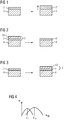
- the gas turbine 100 has a two-layer ceramic thermal barrier coating on the turbine blades 120, 130 during base load operation, to apply a single-layer TBC, so that it can then be used in peak load operation (daily starter) ( Fig. 2 ).
- the ceramic thermal barrier coating on the turbine blades 120, 130 preferably has a high porosity of 18% ⁇ 4%.
- base loader In base load operation (base loader), however, a two-layer thermal insulation layer 13 is used ( Fig. 3 ).
- Agglomerated, sintered powder is preferably used as the starting powder for the ceramic layers 7 ', 7 ", 7'", 10 ', 13'.
- Each ceramic sprayed layer is applied in coating layers.
- two layers means that a second layer differs from a first layer below by porosity and / or microstructure and / or chemical composition.
- a porosity of 25% ⁇ 4% is injected or is present as the outer ceramic layer 10.
- the difference in porosity is at least 2%, in particular at least 4%. Fluctuations in the porosity during production are known. Within a batch, ie a blade set, there are no fluctuations.
- coarse grains can be used during spraying and the use of polymers or smaller grains with polymer can be used, coarse meaning an average particle diameter which is at least 20% larger.
- a two-layer ceramic layer 7, 10 can be produced using various spraying methods: the lower layer 7 is sprayed without polymer and the upper layer 10 is sprayed with polymer.
- the same powder is preferably used here, that is, the same grain size distribution.
- Zirconium oxide (ZrO 2 ) for the ceramic layers of the thermal insulation layers preferably has a monoclinic content of 3 3%, in particular ⁇ 1.5%. Corresponding portions then have a ceramic layer or layer 7, 7 ', 10, 13 ( Figures 1-3 ) on the turbine blade 120, 130.
- the minimum proportion of the monoclinic phase is at least 1%, in particular 0.5%, in order not to increase the powder costs too much.
- the Figure 5 shows a perspective view of a rotor blade 120 or guide blade 130 of a turbomachine, which extends along a longitudinal axis 121.
- the turbomachine can be a gas turbine of an aircraft or a power plant for generating electricity, a steam turbine or a compressor.
- the blade 120, 130 has, in succession along the longitudinal axis 121, a fastening region 400, an adjacent blade platform 403 and an airfoil 406 and a blade tip 415.
- the vane 130 can have a further platform (not shown) at its vane tip 415.
- a blade root 183 is formed in the fastening area 400 and is used to fasten the moving blades 120, 130 to a shaft or a disk (not shown).
- the blade root 183 is designed, for example, as a hammer head. Other configurations as a fir tree or dovetail foot are possible.
- the blade 120, 130 has a leading edge 409 and a trailing edge 412 for a medium flowing past the blade 406.
- blades 120, 130 for example, solid metal materials, in particular super alloys, are used in all areas 400, 403, 406 of blade 120, 130.
- Such superalloys are, for example, from EP 1 204 776 B1 .
- EP 1 306 454 .
- the blade 120, 130 can in this case be produced by a casting process, also by means of directional solidification, by a forging process, by a milling process or combinations thereof.
- Workpieces with a single-crystal structure or structures are used as components for machines that are exposed to high mechanical, thermal and / or chemical loads during operation.
- Such single-crystal workpieces are manufactured e.g. by directional solidification from the melt. These are casting processes in which the liquid metallic alloy forms a single-crystal structure, i.e. to the single-crystalline workpiece, or solidified in a directed manner.
- dendritic crystals are aligned along the heat flow and either form a stem-crystalline grain structure (columnar, i.e. grains that run the entire length of the workpiece and here, according to common usage, are referred to as directionally solidified) or a single-crystalline structure, i.e. the whole workpiece consists of a single crystal.
- a stem-crystalline grain structure columnumnar, i.e. grains that run the entire length of the workpiece and here, according to common usage, are referred to as directionally solidified
- a single-crystalline structure i.e. the whole workpiece consists of a single crystal.
- directionally solidified structures If there is general talk of directionally solidified structures, this means both single crystals which have no grain boundaries or at most small-angle grain boundaries, and stem crystal structures which probably have grain boundaries running in the longitudinal direction but no transverse grain boundaries. These second-mentioned crystalline structures are also referred to as directionally solidified structures.
- the blades 120, 130 may have coatings against corrosion or oxidation, e.g. B. (MCrAlX; M is at least one element from the group iron (Fe), cobalt (Co), nickel (Ni), X is an active element and stands for yttrium (Y) and / or silicon and / or at least one element of the rare Earth or hafnium (Hf)).
- M is at least one element from the group iron (Fe), cobalt (Co), nickel (Ni)
- X is an active element and stands for yttrium (Y) and / or silicon and / or at least one element of the rare Earth or hafnium (Hf)).
- Such alloys are known from the EP 0 486 489 B1 .
- EP 0 412 397 B1 or EP 1 306 454 A1 are known from the EP 0 486 489 B1 .
- the density is preferably 95% of the theoretical density.
- the layer composition preferably has Co-30Ni-28Cr-8Al-0.6Y-0.7Si or Co-28Ni-24Cr-10Al-0.6Y.
- nickel-based protective layers are also preferably used, such as Ni-10Cr-12Al-0.6Y-3Re or Ni-12Co-21Cr-11Al-0.4Y-2Re or Ni-25Co-17Cr-10Al-0.4Y-1 , 5RE.
- a thermal insulation layer which is preferably the outermost layer, may also be present on the MCrAlX and consists, for example, of ZrO 2 , Y 2 O 3 -ZrO 2 , ie it is not, partially or completely stabilized by yttrium oxide and / or calcium oxide and / or magnesium oxide.
- the thermal insulation layer covers the entire MCrAlX layer.
- suitable coating processes such as Electron beam evaporation (EB-PVD) creates stem-shaped grains in the thermal barrier coating.
- the thermal barrier coating can have porous, micro- or macro-cracked grains for better thermal shock resistance.
- the thermal barrier coating is therefore preferably more porous than the MCrAlX layer.
- Refurbishment means that components 120, 130 may have to be freed of protective layers after their use (eg by sandblasting). The corrosion and / or oxidation layers or products are then removed. If necessary, cracks in component 120, 130 are also repaired. This is followed by recoating of component 120, 130 and a renewed use of component 120, 130.
- the blade 120, 130 can be hollow or solid. If the blade 120, 130 is to be cooled, it is hollow and may also have film cooling holes 418 (indicated by dashed lines).
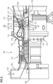
- the Figure 6 shows an example of a gas turbine 100 in a partial longitudinal section.
- the gas turbine 100 has a rotor 103 with a shaft 101 which is rotatably mounted about an axis of rotation 102 and which is also referred to as a turbine rotor.
- the annular combustion chamber 110 communicates with an annular hot gas channel 111, for example.
- annular hot gas channel 111 for example.
- turbine stages 112 connected in series form the turbine 108.
- Each turbine stage 112 is formed, for example, from two blade rings. Seen in the flow direction of a working medium 113, a row 125 of guide vanes is followed by a row 125 formed from rotor blades 120 in the hot gas channel 111.
- the guide vanes 130 are fastened to an inner housing 138 of a stator 143, whereas the rotor blades 120 of a row 125 are attached to the rotor 103, for example by means of a turbine disk 133.
- a generator or a work machine (not shown) is coupled to the rotor 103.
- the compressor 105 draws in and compresses air 135 through the intake housing 104.
- the one provided at the turbine end of the compressor 105 compressed air is fed to the burners 107 and mixed there with a fuel.
- the mixture is then burned in the combustion chamber 110 to form the working medium 113.
- the working medium 113 flows along the hot gas channel 111 past the guide vanes 130 and the moving blades 120.
- the working medium 113 relaxes in a pulse-transmitting manner on the moving blades 120, so that the moving blades 120 drive the rotor 103 and the working machine coupled to it.
- the components exposed to the hot working medium 113 are subject to thermal loads during the operation of the gas turbine 100.
- the guide blades 130 and blades 120 of the first turbine stage 112, as seen in the flow direction of the working medium 113, are subjected to the greatest thermal stress in addition to the heat shield elements lining the annular combustion chamber 110.
- substrates of the components can have a directional structure, i.e. they are single-crystal (SX structure) or only have longitudinal grains (DS structure).
- SX structure single-crystal
- DS structure longitudinal grains
- iron, nickel or cobalt-based superalloys are used as the material for the components, in particular for the turbine blade 120, 130 and components of the combustion chamber 110.
- Such superalloys are, for example, from the EP 1 204 776 B1 .
- EP 1 306 454 .
- the blades 120, 130 can have coatings against corrosion (MCrAlX; M is at least one element from the group iron (Fe), cobalt (Co), nickel (Ni), X is an active element and stands for yttrium (Y) and / or silicon , Scandium (Sc) and / or at least one element of the rare earths or hafnium).
- M is at least one element from the group iron (Fe), cobalt (Co), nickel (Ni)
- X is an active element and stands for yttrium (Y) and / or silicon , Scandium (Sc) and / or at least one element of the rare earths or hafnium).
- Such alloys are known from the EP 0 486 489 B1 .
- EP 0 412 397 B1 or EP 1 306 454 A1 are known from the EP 0 486 489 B1 .
- a thermal insulation layer may also be present on the MCrAlX and consists, for example, of ZrO 2 , Y 2 O 3 -ZrO 2 , ie it is not partially or completely stabilized by yttrium oxide and / or calcium oxide and / or magnesium oxide.
- Electron beam evaporation creates stem-shaped grains in the thermal barrier coating.
- the guide vane 130 has a guide vane foot (not shown here) facing the inner casing 138 of the turbine 108 and a guide vane head opposite the guide vane foot.
- the guide vane head faces the rotor 103 and is fixed to a fastening ring 140 of the stator 143.
Landscapes
- Engineering & Computer Science (AREA)
- Mechanical Engineering (AREA)
- General Engineering & Computer Science (AREA)
- Chemical & Material Sciences (AREA)
- Materials Engineering (AREA)
- Life Sciences & Earth Sciences (AREA)
- Wood Science & Technology (AREA)
- Turbine Rotor Nozzle Sealing (AREA)
- Coating By Spraying Or Casting (AREA)
Description
- Die Erfindung betrifft ein Verfahren zur Herstellung von Gasturbinen, die flexibel ausgelegt werden, und eine Verwendung von Gasturbinen.
- Gasturbinen können bei der Stromerzeugung im Grundlastbetrieb oder insbesondere im Spitzenlastbetrieb betrieben werden.
- Die Anforderungen an die jeweiligen Bedingungen sind unterschiedlich.
- Eine optimierte Konfiguration der Gasturbine, die beide Anforderungen erfüllt, würde immer einen Kompromiss darstellen.
- Es ist daher Aufgabe der Erfindung dieses Problem zu lösen.
- Die Aufgabe wird gelöst durch ein Verfahren zur Herstellung einer zweiten Gasturbine gemäß Anspruch 1 und eine Verwendung gemäß Anspruch 17.
- In den Unteransprüchen sind weitere vorteilhafte Maßnahmen aufgelistet, die beliebig miteinander kombiniert werden können, um weitere Vorteile zu erzielen.
- Es zeigen:
- Figur 1 - 3
- Ausführungsbeispiel der Erfindung,
- Figur 4
- eine Porenverteilung keramischer Schicht,
- Figur 5
- eine Turbinenschaufel und
- Figur 6
- eine Gasturbine.
- Die Beschreibung stellt nur ein Ausführungsbeispiel der Erfindung dar.
- Ein Intervall der Wartung von Gasturbinen 100 (
Fig. 6 ) wird bestimmt durch Erfassung der Betriebsstunden und Starts, die abhängig von der Betriebsweise und bestimmten Faktoren sind. Die Wartung ist jeweils nach Erreichen des Stunden- oder Startlimits durchzuführen. - Ist nun je nach Einsatzgebiet der Gasturbine eine Wartung notwendig oder verlangt der Einsatz vorab eine Überholung bzw. einen anderen Einsatz, so wird die Konfiguration der Gasturbine 100 geändert.
- Erste Gasturbine hat 1. Turbinenschaufel mit 1. Wärmedämmschicht.
- Zweite Gasturbine hat Turbinenschaufeln mit keramischen Wärmedämmschichten
- a) bei denen die 1. Turbinenschaufeln (=zweite Turbinenschaufel) und/oder
- b) neue unverbrauchte Turbinenschaufeln (= neue zweite Turbinenschaufeln)
- War vorher in dieser ersten Gasturbine eine einlagige Wärmedämmschicht wie oben beschrieben im Betrieb vorhanden, so wird für den erneuten Einsatz im Grundlastbetrieb eine zweilagige (
Fig. 3 ), eine dickere (Fig. 1 ) oder porösere keramische Wärmedämmschicht für die Turbinenschaufeln 120, 130 verwendet. - Die Turbinenschaufeln für die zweite Gasturbine können im Ursprung (dasselbe Substrat) die ersten Turbinenschaufeln der ersten Gasturbine oder anderer Gasturbinen sein, die bereits im Einsatz waren, entsprechend aufgearbeitet wurden (Refurbishment) und durch eine Wiederbeschichtung zweite Turbinenschaufeln ergeben oder neue zweite Turbinenschaufeln sein, bei denen neu hergestellte (neu gegossene), noch nicht verwendete Turbinenschaufeln anders als die ersten Turbinenschaufeln der ersten Gasturbine beschichtet werden.
- Ebenso ist es möglich, wenn die Gasturbine 100 im Grundlastbetrieb eine zweilagige keramische Wärmedämmschicht auf den Turbinenschaufeln 120, 130 aufgewiesen hat, eine einlagige TBC aufzubringen, so dass sie dann im Spitzenlastbetrieb (daily starter) eingesetzt werden kann (
Fig. 2 ). - Für den Spitzenlastbetrieb wird vorzugsweise nur eine einlagige keramische Schicht mit einer einheitlichen Porosität verwendet. Für den Spitzenlastbetrieb weist die keramische Wärmedämmschicht auf den Turbinenschaufeln 120, 130 vorzugsweise eine hohe Porosität von 18% ± 4% auf.
- Im Grundlastbetrieb (base loader) wird jedoch eine zweilagige Wärmedämmschicht 13 eingesetzt (
Fig. 3 ). - Als Ausgangspulver für die keramischen Schichten 7', 7", 7'", 10', 13' wird vorzugsweise agglomeriertes, gesintertes Pulver verwendet.
- Jede keramische gespritzte Schicht wird in Beschichtungslagen aufgebracht. Zweilagigkeit bedeutet aber, dass sich eine zweite Lage durch Porosität und/oder Mikrostruktur und/oder chemische Zusammensetzung von einer ersten, untenliegenden Lage unterscheidet.
- Als untere Lage wird vorzugsweise eine keramische Lage 7 mit einer Porosität von 12% ± 4% verwendet, die vorzugsweise eine Schichtdicke von 75µm bis 150µm aufweist.
- Darüber wird als äußere keramische Lage 10 eine Porosität mit 25% ± 4% gespritzt bzw. ist vorhanden.
- Der Unterschied in der Porosität beträgt jedoch mindestens 2%, insbesondere mindestens 4%. Schwankungen in der Porosität bei der Herstellung sind bekannt. Innerhalb einer Charge, d.h. eines Schaufelsatzes, sind keine Schwankungen zu verzeichnen.
- Um Porositäten in keramischen Schichten oder keramischen Lagen (
Figuren 1 - 3 ) zu erzeugen, können beim Spritzen grobe Körner verwendet werden und Verwendung von Polymeren oder kleinere Körner mit Polymer verwendet werden, wobei grob einen mindestens 20% größeren mittleren Teilchendurchmesser bedeutet. - Eine zweilagige keramische Schicht 7, 10 kann mit verschiedenen Spritzverfahren hergestellt werden: die untere Lage 7 wird ohne Polymer und die obere Lage 10 wird mit Polymer verspritzt.
- Dadurch ergeben sich in der oberen Lage 10 größere Poren, d.h. der mittlere Porendurchmesser d10 steigt gegenüber dem mittleren Porendurchmesser d7 der unteren Lage 7 (
Fig. 4 ) an. Dies ist nicht zwangsläufig so. Eine höhere Porosität wird oft nur durch eine höhere Anzahl Poren der gleichen Porengröße erzielt. - Vorzugsweise wird das gleiche Pulver dabei verwendet, also auch eine gleiche Korngrößenverteilung.
- Zirkonoxid (ZrO2) für die keramischen Lagen der Wärmedämmschichten weist vorzugsweise einen monoklinen Anteil von ≤ 3%, insbesondere ≤ 1,5% aufweist. Dementsprechende Anteile weist dann eine keramische Lage oder Schicht 7, 7', 10, 13 (
Figuren 1 - 3 ) auf der Turbinenschaufel 120, 130 auf. - Der Minimumanteil der monoklinen Phase beträgt mindestens 1%, insbesondere 0,5%, um die Kosten des Pulvers nicht zu stark zu erhöhen.
- Durch die Veränderung der Konfiguration der ersten Wärmedämmschicht 7', 7", 13' wird quasi eine andere, zweite Gasturbine hergestellt, die optimiert ist auf ihr Einsatzgebiet.
- Die
Figur 5 zeigt in perspektivischer Ansicht eine Laufschaufel 120 oder Leitschaufel 130 einer Strömungsmaschine, die sich entlang einer Längsachse 121 erstreckt. - Die Strömungsmaschine kann eine Gasturbine eines Flugzeugs oder eines Kraftwerks zur Elektrizitätserzeugung, eine Dampfturbine oder ein Kompressor sein.
- Die Schaufel 120, 130 weist entlang der Längsachse 121 aufeinander folgend einen Befestigungsbereich 400, eine daran angrenzende Schaufelplattform 403 sowie ein Schaufelblatt 406 und eine Schaufelspitze 415 auf.
- Als Leitschaufel 130 kann die Schaufel 130 an ihrer Schaufelspitze 415 eine weitere Plattform aufweisen (nicht dargestellt) .
- Im Befestigungsbereich 400 ist ein Schaufelfuß 183 gebildet, der zur Befestigung der Laufschaufeln 120, 130 an einer Welle oder einer Scheibe dient (nicht dargestellt).
- Der Schaufelfuß 183 ist beispielsweise als Hammerkopf ausgestaltet. Andere Ausgestaltungen als Tannenbaum- oder Schwalbenschwanzfuß sind möglich.
- Die Schaufel 120, 130 weist für ein Medium, das an dem Schaufelblatt 406 vorbeiströmt, eine Anströmkante 409 und eine Abströmkante 412 auf.
- Bei herkömmlichen Schaufeln 120, 130 werden in allen Bereichen 400, 403, 406 der Schaufel 120, 130 beispielsweise massive metallische Werkstoffe, insbesondere Superlegierungen verwendet.
- Solche Superlegierungen sind beispielsweise aus der
EP 1 204 776 B1 ,EP 1 306 454 ,EP 1 319 729 A1 ,WO 99/67435 WO 00/44949 - Die Schaufel 120, 130 kann hierbei durch ein Gussverfahren, auch mittels gerichteter Erstarrung, durch ein Schmiedeverfahren, durch ein Fräsverfahren oder Kombinationen daraus gefertigt sein.
- Werkstücke mit einkristalliner Struktur oder Strukturen werden als Bauteile für Maschinen eingesetzt, die im Betrieb hohen mechanischen, thermischen und/oder chemischen Belastungen ausgesetzt sind.
- Die Fertigung von derartigen einkristallinen Werkstücken erfolgt z.B. durch gerichtetes Erstarren aus der Schmelze. Es handelt sich dabei um Gießverfahren, bei denen die flüssige metallische Legierung zur einkristallinen Struktur, d.h. zum einkristallinen Werkstück, oder gerichtet erstarrt.
- Dabei werden dendritische Kristalle entlang dem Wärmefluss ausgerichtet und bilden entweder eine stängelkristalline Kornstruktur (kolumnar, d.h. Körner, die über die ganze Länge des Werkstückes verlaufen und hier, dem allgemeinen Sprachgebrauch nach, als gerichtet erstarrt bezeichnet werden) oder eine einkristalline Struktur, d.h. das ganze Werkstück besteht aus einem einzigen Kristall. In diesen Verfahren muss man den Übergang zur globulitischen (polykristallinen) Erstarrung meiden, da sich durch ungerichtetes Wachstum notwendigerweise transversale und longitudinale Korngrenzen ausbilden, welche die guten Eigenschaften des gerichtet erstarrten oder einkristallinen Bauteiles zunichte machen.
- Ist allgemein von gerichtet erstarrten Gefügen die Rede, so sind damit sowohl Einkristalle gemeint, die keine Korngrenzen oder höchstens Kleinwinkelkorngrenzen aufweisen, als auch Stängelkristallstrukturen, die wohl in longitudinaler Richtung verlaufende Korngrenzen, aber keine transversalen Korngrenzen aufweisen. Bei diesen zweitgenannten kristallinen Strukturen spricht man auch von gerichtet erstarrten Gefügen (directionally solidified structures).
- Solche Verfahren sind aus der US-PS
6,024,792 und derEP 0 892 090 A1 bekannt. - Ebenso können die Schaufeln 120, 130 Beschichtungen gegen Korrosion oder Oxidation aufweisen, z. B. (MCrAlX; M ist zumindest ein Element der Gruppe Eisen (Fe), Kobalt (Co), Nickel (Ni), X ist ein Aktivelement und steht für Yttrium (Y) und/oder Silizium und/oder zumindest ein Element der Seltenen Erden, bzw. Hafnium (Hf)). Solche Legierungen sind bekannt aus der
EP 0 486 489 B1 ,EP 0 786 017 B1 ,EP 0 412 397 B1 oderEP 1 306 454 A1 . - Die Dichte liegt vorzugsweise bei 95% der theoretischen Dichte.
- Auf der MCrAlX-Schicht (als Zwischenschicht oder als äußerste Schicht) bildet sich eine schützende Aluminiumoxidschicht (TGO = thermal grown oxide layer).
- Vorzugsweise weist die Schichtzusammensetzung Co-30Ni-28Cr-8Al-0,6Y-0,7Si oder Co-28Ni-24Cr-10Al-0,6Y auf. Neben diesen kobaltbasierten Schutzbeschichtungen werden auch vorzugsweise nickelbasierte Schutzschichten verwendet wie Ni-10Cr-12Al-0,6Y-3Re oder Ni-12Co-21Cr-11Al-0,4Y-2Re oder Ni-25Co-17Cr-10Al-0,4Y-1,5Re.
- Auf der MCrAlX kann noch eine Wärmedämmschicht vorhanden sein, die vorzugsweise die äußerste Schicht ist, und besteht beispielsweise aus ZrO2, Y2O3-ZrO2, d.h. sie ist nicht, teilweise oder vollständig stabilisiert durch Yttriumoxid und/oder Kalziumoxid und/oder Magnesiumoxid.
- Die Wärmedämmschicht bedeckt die gesamte MCrAlX-Schicht. Durch geeignete Beschichtungsverfahren wie z.B. Elektronenstrahlverdampfen (EB-PVD) werden stängelförmige Körner in der Wärmedämmschicht erzeugt.
- Andere Beschichtungsverfahren sind denkbar, z.B. atmosphärisches Plasmaspritzen (APS), LPPS, VPS oder CVD. Die Wärmedämmschicht kann poröse, mikro- oder makrorissbehaftete Körner zur besseren Thermoschockbeständigkeit aufweisen. Die Wärmedämmschicht ist also vorzugsweise poröser als die MCrAlX-Schicht.
- Wiederaufarbeitung (Refurbishment) bedeutet, dass Bauteile 120, 130 nach ihrem Einsatz gegebenenfalls von Schutzschichten befreit werden müssen (z.B. durch Sandstrahlen). Danach erfolgt eine Entfernung der Korrosions- und/oder Oxidationsschichten bzw. -produkte. Gegebenenfalls werden auch noch Risse im Bauteil 120, 130 repariert. Danach erfolgt eine Wiederbeschichtung des Bauteils 120, 130 und ein erneuter Einsatz des Bauteils 120, 130.
- Die Schaufel 120, 130 kann hohl oder massiv ausgeführt sein. Wenn die Schaufel 120, 130 gekühlt werden soll, ist sie hohl und weist ggf. noch Filmkühllöcher 418 (gestrichelt angedeutet) auf.
- Die
Figur 6 zeigt beispielhaft eine Gasturbine 100 in einem Längsteilschnitt. - Die Gasturbine 100 weist im Inneren einen um eine Rotationsachse 102 drehgelagerten Rotor 103 mit einer Welle 101 auf, der auch als Turbinenläufer bezeichnet wird.
- Entlang des Rotors 103 folgen aufeinander ein Ansauggehäuse 104, ein Verdichter 105, eine beispielsweise torusartige Brennkammer 110, insbesondere Ringbrennkammer, mit mehreren koaxial angeordneten Brennern 107, eine Turbine 108 und das Abgasgehäuse 109.
- Die Ringbrennkammer 110 kommuniziert mit einem beispielsweise ringförmigen Heißgaskanal 111. Dort bilden beispielsweise vier hintereinander geschaltete Turbinenstufen 112 die Turbine 108.
- Jede Turbinenstufe 112 ist beispielsweise aus zwei Schaufelringen gebildet. In Strömungsrichtung eines Arbeitsmediums 113 gesehen folgt im Heißgaskanal 111 einer Leitschaufelreihe 115 eine aus Laufschaufeln 120 gebildete Reihe 125.
- Die Leitschaufeln 130 sind dabei an einem Innengehäuse 138 eines Stators 143 befestigt, wohingegen die Laufschaufeln 120 einer Reihe 125 beispielsweise mittels einer Turbinenscheibe 133 am Rotor 103 angebracht sind.
- An dem Rotor 103 angekoppelt ist ein Generator oder eine Arbeitsmaschine (nicht dargestellt).
- Während des Betriebes der Gasturbine 100 wird vom Verdichter 105 durch das Ansauggehäuse 104 Luft 135 angesaugt und verdichtet. Die am turbinenseitigen Ende des Verdichters 105 bereitgestellte verdichtete Luft wird zu den Brennern 107 geführt und dort mit einem Brennmittel vermischt. Das Gemisch wird dann unter Bildung des Arbeitsmediums 113 in der Brennkammer 110 verbrannt. Von dort aus strömt das Arbeitsmedium 113 entlang des Heißgaskanals 111 vorbei an den Leitschaufeln 130 und den Laufschaufeln 120. An den Laufschaufeln 120 entspannt sich das Arbeitsmedium 113 impulsübertragend, so dass die Laufschaufeln 120 den Rotor 103 antreiben und dieser die an ihn angekoppelte Arbeitsmaschine.
- Die dem heißen Arbeitsmedium 113 ausgesetzten Bauteile unterliegen während des Betriebes der Gasturbine 100 thermischen Belastungen. Die Leitschaufeln 130 und Laufschaufeln 120 der in Strömungsrichtung des Arbeitsmediums 113 gesehen ersten Turbinenstufe 112 werden neben den die Ringbrennkammer 110 auskleidenden Hitzeschildelementen am meisten thermisch belastet.
- Um den dort herrschenden Temperaturen standzuhalten, können diese mittels eines Kühlmittels gekühlt werden.
- Ebenso können Substrate der Bauteile eine gerichtete Struktur aufweisen, d.h. sie sind einkristallin (SX-Struktur) oder weisen nur längsgerichtete Körner auf (DS-Struktur).
- Als Material für die Bauteile, insbesondere für die Turbinenschaufel 120, 130 und Bauteile der Brennkammer 110 werden beispielsweise eisen-, nickel- oder kobaltbasierte Superlegierungen verwendet.
- Solche Superlegierungen sind beispielsweise aus der
EP 1 204 776 B1 ,EP 1 306 454 ,EP 1 319 729 A1 ,WO 99/67435 WO 00/44949 - Ebenso können die Schaufeln 120, 130 Beschichtungen gegen Korrosion (MCrAlX; M ist zumindest ein Element der Gruppe Eisen (Fe), Kobalt (Co), Nickel (Ni), X ist ein Aktivelement und steht für Yttrium (Y) und/oder Silizium, Scandium (Sc) und/oder zumindest ein Element der Seltenen Erden bzw. Hafnium). Solche Legierungen sind bekannt aus der
EP 0 486 489 B1 ,EP 0 786 017 B1 ,EP 0 412 397 B1 oderEP 1 306 454 A1 . - Auf der MCrAlX kann noch eine Wärmedämmschicht vorhanden sein, und besteht beispielsweise aus ZrO2, Y2O3-ZrO2, d.h. sie ist nicht, teilweise oder vollständig stabilisiert durch Yttriumoxid und/oder Kalziumoxid und/oder Magnesiumoxid.
- Durch geeignete Beschichtungsverfahren wie z.B. Elektronenstrahlverdampfen (EB-PVD) werden stängelförmige Körner in der Wärmedämmschicht erzeugt.
- Die Leitschaufel 130 weist einen dem Innengehäuse 138 der Turbine 108 zugewandten Leitschaufelfuß (hier nicht dargestellt) und einen dem Leitschaufelfuß gegenüberliegenden Leitschaufelkopf auf. Der Leitschaufelkopf ist dem Rotor 103 zugewandt und an einem Befestigungsring 140 des Stators 143 festgelegt.
und jeweils eine 2. Wärmedämmschicht deutlich unterscheidbar von der 1. Wärmedämmschicht aufweisen.
Claims (19)
- Verfahren zur Herstellung einer zweiten Gasturbine, bei dem ausgehend von einer ersten Gasturbine von ersten Turbinenschaufeln der ersten Gasturbine zumindest eine erste keramische Wärmedämmschicht (7, 13) entfernt wird und eine neue zweite keramische Wärmedämmschicht (7', 7", 13') zur Herstellung zweiter Turbinenschaufeln (7) auf die entschichteten ersten Turbinenschaufeln aufgebracht wird, und/oder
auf neue zweite Turbinenschaufeln,
die neu hergestellt wurden,
eine neue zweite keramische Wärmedämmschicht (7', 7", 13') aufgebracht wird,
die (7', 7", 13') sich von der ersten keramischen Wärmedämmschicht (7, 13) deutlich unterscheidet,
nämlich dass die Porosität unterschiedlich ist,
wobei der absolute Unterschied in der verkleinerten oder vergrößerten Porosität mindestens 2% beträgt,
wobei Unterscheidung zumindest weiterhin bedeutet:die Schichtdicke ist unterschiedlich,wobei der Unterschied in der reduzierten und vergrößerten Schichtdicke mindestens 50µm beträgt,und/oderdie Lagigkeit ist unterschiedlich,wobeientweder eine zweilagige keramische Wärmedämmschicht (13) von den ersten Turbinenschaufeln entfernt wird und eine einlagige Wärmedämmschicht (7") als zweite keramische Wärmedämmschicht auf die zweiten oder neuen zweiten Turbinenschaufeln aufgebracht wird,oderwobei eine einlagige Wärmedämmschicht (7) von den ersten Turbinenschaufeln entfernt wird und eine zweilagige Wärmedämmschicht (13') als zweite keramische Wärmedämmschicht auf die zweiten oder neuen zweiten Turbinenschaufeln aufgebracht wird,insbesondere eine nur zweilagige Wärmedämmschicht (13') und wobei die neuen zweiten und/oder die zweiten Turbinenschaufeln in die zweite Gasturbine eingebaut werden. - Verfahren nach Anspruch 1,
bei dem die einlagige keramische Wärmedämmschicht (7") mit einer Porosität von 18% ± 4% erzeugt wird. - Verfahren nach einem oder beiden der Ansprüche 1 oder 2,
bei dem die Porosität der zweiten keramischen Wärmedämmschicht (7', 7", 13') der zweiten oder der neuen zweiten Turbinenschaufeln gegenüber der Porosität der Wärmedämmschicht der ersten Turbinenschaufeln erhöht wird. - Verfahren nach einem oder beiden der Ansprüche 1 oder 2,
bei dem die Porosität der zweiten keramischen Wärmedämmschicht (7', 7", 13) der zweiten oder der neuen zweiten Turbinenschaufeln gegenüber der Porosität der Wärmedämmschicht der ersten Turbinenschaufeln erniedrigt wird. - Verfahren nach einem oder mehreren der Ansprüche 1 bis 3,
bei dem eine dünnere keramische Wärmedämmschicht (7) als erste keramische Wärmedämmschicht ersetzt wird durch eine dickere keramische Wärmedämmschicht (7', 13') als zweite keramische Wärmedämmschicht der zweiten oder der neuen zweiten Turbinenschaufeln,
wobei der Unterschied in der Dicke mindestens +50µm beträgt. - Verfahren nach einem oder mehreren der Ansprüche 1 bis 4,
bei dem eine dickere keramische Wärmedämmschicht als erste keramische Wärmedämmschicht ersetzt wird durch eine dünnere keramische Wärmedämmschicht als zweite keramische Wärmedämmschicht der zweiten oder der neuen zweiten Turbinenschaufeln,
wobei der Unterschied in der Dicke mindestens -50µm beträgt. - Verfahren nach einem oder mehreren der Ansprüche 1, 3 bis 6,
bei dem eine zweilagige Wärmedämmschicht (13') mit einer untersten keramischen Lage (7'") mit einer Porosität von 12% ± 4% und
mit einer äußeren keramischen Lage (10') mit einer Porosität von 25% ± 4% erzeugt wird,
wobei der absolute Unterschied in der Porosität der keramischen Schichten (7'", 10') mindestens 2%, insbesondere mindestens 4% beträgt. - Verfahren nach einem oder mehreren der Ansprüche 1, 3 bis 7,
bei dem die untere Lage (7'") der zweilagigen Wärmedämmschicht (13) dünner, insbesondere mindestens 20% dünner ausgeführt ist als die obere Lage (10'),
insbesondere bei dem die untere Lage (7"') der zweilagigen Wärmedämmschicht (13) eine Dicke von 75µm bis 150µm aufweist,
ganz insbesondere die Gesamtschichtdicke der zweilagigen Wärmedämmschicht (13) 500µm bis 800µm beträgt. - Verfahren nach einem oder mehreren der Ansprüche 1, 3 bis 8,
bei dem für die untere keramische Lage (7'") teilstabilisiertes Zirkonoxid und
für die obere keramische Lage (10') teilstabilisiertes Zirkonoxid verwendet wird. - Verfahren nach einem oder mehreren der vorherigen Ansprüche,
bei dem Zirkonoxid für die keramische Wärmedämmschicht (7', 7", 13') oder die keramischen Lagen (7"', 10') verwendet wird,
und der monokline Anteil des zu verspritzenden Pulvers unter 3%,
insbesondere unter 1,5% liegt,
ganz insbesondere mindestens 0,3% beträgt. - Verfahren nach einem oder beiden der Ansprüche 9 oder 10,
bei dem der tetragonale Anteil in Zirkonoxid den größten Anteil aufweist,
insbesondere mindestens 60%,
ganz insbesondere mindestens 75%. - Verfahren nach Anspruch 10 oder 11,
bei dem durch eine Wärmebehandlung der monokline Anteil des Zirkonoxids,
insbesondere des zu verspritzenden Pulvers,
um mindestens 50% reduziert wird,
insbesondere unter die Nachweisgrenze. - Verfahren nach einem oder mehreren der Ansprüche 1, 3 bis 12,
bei dem die untere Lage (7'") ohne Polymer verspritzt wird und die obere Lage (10') mit Polymer verspritzt wird. - Verfahren nach einem oder mehreren der Ansprüche 1, 3 bis 13,
bei dem der mittlere Porendurchmesser (d10) der oberen keramischen Lage (10') größer erzeugt wird als der mittlere Porendurchmesser (d7) der unteren keramischen Lage (7"'), ganz insbesondere um mindestens 20µm. - Verfahren nach einem oder mehreren der Ansprüche 1, 3 bis 14,
bei dem das gleiche Pulver mit gleicher Zusammensetzung und gleicher Korngrößenverteilung verwendet wird. - Verfahren nach Anspruch 1, 3 bis 14,
bei dem für die untere keramische Lage (7"') ein anderes Material verwendet wird als für die obere keramische Lage (10'),
insbesondere Zirkonoxid für die untere Lage (7'"), ganz insbesondere ein Pyrochlor für die obere Lage (10'). - Verwendung einer Gasturbinenanlage, bei der die Art von keramischen Schichten von Turbinenschaufeln der Gasturbine (100) gemäss Anspruch 1 verändert wird.
- Verwendnug einer Gasturbinenanlage nach Anspruch 17, wobei tägliche Starts der Gasturbine erfolgen.
- Verwendung einer Gasturbinenanlage nach Anspruch 18, wobei die Gasturbine mehrere Tage kontinuierlich in Betrieb ist.
Applications Claiming Priority (1)
| Application Number | Priority Date | Filing Date | Title |
|---|---|---|---|
| PCT/EP2012/069700 WO2014053185A1 (de) | 2012-10-05 | 2012-10-05 | Verfahren zur aufbereitung einer gasturbinenschaufel sowie gasturbine mit derartiger schaufel |
Publications (2)
| Publication Number | Publication Date |
|---|---|
| EP2882939A1 EP2882939A1 (de) | 2015-06-17 |
| EP2882939B1 true EP2882939B1 (de) | 2020-01-08 |
Family
ID=47018990
Family Applications (1)
| Application Number | Title | Priority Date | Filing Date |
|---|---|---|---|
| EP12772752.7A Revoked EP2882939B1 (de) | 2012-10-05 | 2012-10-05 | Verfahren zur aufbereitung einer gasturbinenschaufel sowie verwendung einer gasturbine mit derartiger schaufel |
Country Status (6)
| Country | Link |
|---|---|
| US (2) | US10215034B2 (de) |
| EP (1) | EP2882939B1 (de) |
| KR (1) | KR20150060960A (de) |
| CN (1) | CN104704200B (de) |
| RU (1) | RU2618988C2 (de) |
| WO (1) | WO2014053185A1 (de) |
Cited By (1)
| Publication number | Priority date | Publication date | Assignee | Title |
|---|---|---|---|---|
| WO2013143631A1 (de) | 2012-03-28 | 2013-10-03 | Siemens Aktiengesellschaft | Verfahren zur herstellung und wiederherstellung von keramischen wärmedämmschichten in gasturbinen sowie dazugehörige gasturbine |
Families Citing this family (5)
| Publication number | Priority date | Publication date | Assignee | Title |
|---|---|---|---|---|
| DE102013226594A1 (de) * | 2013-12-19 | 2015-06-25 | Robert Bosch Gmbh | Verfahren zum Herstellen eines Laufrads und eines Läufers |
| DE102015206321A1 (de) * | 2015-04-09 | 2016-10-13 | Siemens Aktiengesellschaft | Zweilagige keramische Wärmedämmschicht mit Übergangszone |
| FR3058469B1 (fr) * | 2016-11-09 | 2020-08-21 | Safran | Piece de turbomachine revetue d'une barriere thermique et procede pour l'obtenir |
| DE102017207238A1 (de) | 2017-04-28 | 2018-10-31 | Siemens Aktiengesellschaft | Dichtungssystem für Laufschaufel und Gehäuse |
| US11655720B2 (en) | 2020-06-19 | 2023-05-23 | General Electric Company | Methods and materials for repairing a thermal barrier coating of a gas turbine component |
Citations (7)
| Publication number | Priority date | Publication date | Assignee | Title |
|---|---|---|---|---|
| US5972424A (en) | 1998-05-21 | 1999-10-26 | United Technologies Corporation | Repair of gas turbine engine component coated with a thermal barrier coating |
| US20040057832A1 (en) | 2001-04-03 | 2004-03-25 | Robert Fleck | Gas turbine blade |
| US20050106316A1 (en) | 2003-11-13 | 2005-05-19 | General Electric Company | Method for repairing coated components |
| US20060029723A1 (en) | 2003-11-13 | 2006-02-09 | General Electric Company | Method for repairing coated components using nial bond coats |
| WO2007112783A1 (de) | 2006-04-06 | 2007-10-11 | Siemens Aktiengesellschaft | Layered thermal barrier coating with a high porosity, and a component |
| EP2450465A1 (de) | 2010-11-09 | 2012-05-09 | Siemens Aktiengesellschaft | Poröses Schichtsystem mit poröserer Innenschicht |
| EP2644824A1 (de) | 2012-03-28 | 2013-10-02 | Siemens Aktiengesellschaft | Verfahren zur Herstellung und Wiederherstellung von keramischen Wärmedämmschichten in Gasturbinen sowie dazugehörige Gasturbine |
Family Cites Families (41)
| Publication number | Priority date | Publication date | Assignee | Title |
|---|---|---|---|---|
| US4299865A (en) * | 1979-09-06 | 1981-11-10 | General Motors Corporation | Abradable ceramic seal and method of making same |
| DE3742038A1 (de) | 1987-12-11 | 1989-06-22 | Gerd Braasch | Schleifkoerper fuer die bearbeitung von oberflaechen, insbesondere holzoberflaechen |
| US5268238A (en) | 1989-08-10 | 1993-12-07 | Siemens Aktiengesellschaft | Highly corrosion and/or oxidation-resistant protective coating containing rhenium applied to gas turbine component surface and method thereof |
| DE3926479A1 (de) | 1989-08-10 | 1991-02-14 | Siemens Ag | Rheniumhaltige schutzbeschichtung, mit grosser korrosions- und/oder oxidationsbestaendigkeit |
| JP2773050B2 (ja) | 1989-08-10 | 1998-07-09 | シーメンス アクチエンゲゼルシヤフト | 耐熱性耐食性の保護被覆層 |
| US5401307A (en) | 1990-08-10 | 1995-03-28 | Siemens Aktiengesellschaft | High temperature-resistant corrosion protection coating on a component, in particular a gas turbine component |
| US5350557A (en) * | 1991-09-23 | 1994-09-27 | Technetics Corp. | Impermeable, abradable seal and method for the production thereof |
| WO1996012049A1 (de) | 1994-10-14 | 1996-04-25 | Siemens Aktiengesellschaft | Schutzschicht zum schutz eines bauteils gegen korrosion, oxidation und thermische überbeanspruchung sowie verfahren zu ihrer herstellung |
| US6465090B1 (en) * | 1995-11-30 | 2002-10-15 | General Electric Company | Protective coating for thermal barrier coatings and coating method therefor |
| EP0861927A1 (de) | 1997-02-24 | 1998-09-02 | Sulzer Innotec Ag | Verfahren zum Herstellen von einkristallinen Strukturen |
| EP0892090B1 (de) | 1997-02-24 | 2008-04-23 | Sulzer Innotec Ag | Verfahren zum Herstellen von einkristallinen Strukturen |
| EP1306454B1 (de) | 2001-10-24 | 2004-10-06 | Siemens Aktiengesellschaft | Rhenium enthaltende Schutzschicht zum Schutz eines Bauteils gegen Korrosion und Oxidation bei hohen Temperaturen |
| US20040180233A1 (en) | 1998-04-29 | 2004-09-16 | Siemens Aktiengesellschaft | Product having a layer which protects against corrosion. and process for producing a layer which protects against corrosion |
| WO1999067435A1 (en) | 1998-06-23 | 1999-12-29 | Siemens Aktiengesellschaft | Directionally solidified casting with improved transverse stress rupture strength |
| US6231692B1 (en) | 1999-01-28 | 2001-05-15 | Howmet Research Corporation | Nickel base superalloy with improved machinability and method of making thereof |
| JP2003529677A (ja) | 1999-07-29 | 2003-10-07 | シーメンス アクチエンゲゼルシヤフト | 耐熱性の構造部材及びその製造方法 |
| US6296447B1 (en) | 1999-08-11 | 2001-10-02 | General Electric Company | Gas turbine component having location-dependent protective coatings thereon |
| US20030203224A1 (en) * | 2001-07-30 | 2003-10-30 | Diconza Paul Josesh | Thermal barrier coating of intermediate density |
| US8357454B2 (en) * | 2001-08-02 | 2013-01-22 | Siemens Energy, Inc. | Segmented thermal barrier coating |
| US6924046B2 (en) | 2001-10-24 | 2005-08-02 | Siemens Aktiengesellschaft | Rhenium-containing protective layer for protecting a component against corrosion and oxidation at high temperatures |
| DE50112339D1 (de) | 2001-12-13 | 2007-05-24 | Siemens Ag | Hochtemperaturbeständiges Bauteil aus einkristalliner oder polykristalliner Nickel-Basis-Superlegierung |
| US20040115470A1 (en) * | 2002-12-12 | 2004-06-17 | Ackerman John Frederick | Thermal barrier coating protected by infiltrated alumina and method for preparing same |
| US20080163962A1 (en) | 2003-05-05 | 2008-07-10 | John Corrigan | Directionally solidified casting with improved transverse stress rupture strength |
| EP1491658A1 (de) * | 2003-06-26 | 2004-12-29 | ALSTOM Technology Ltd | Verfahren für das Auftragen eines mehrschichtigen Systems |
| JP4969094B2 (ja) | 2004-12-14 | 2012-07-04 | 三菱重工業株式会社 | 遮熱コーティング部材及びその製造並びにガスタービン |
| JP4815797B2 (ja) * | 2004-12-14 | 2011-11-16 | 船井電機株式会社 | 受光装置 |
| CA2529781C (en) | 2004-12-14 | 2010-10-12 | Mitsubishi Heavy Industries, Ltd. | Thermal barrier coating material, thermal barrier member, and member coated with thermal barrier and method for manufacturing the same |
| US7416788B2 (en) * | 2005-06-30 | 2008-08-26 | Honeywell International Inc. | Thermal barrier coating resistant to penetration by environmental contaminants |
| EP1806430A1 (de) | 2006-01-09 | 2007-07-11 | Siemens Aktiengesellschaft | Keramische Schicht mit hoher Porosität, Verwendung dieser Schicht sowie ein Bauteil mit dieser Schicht |
| US20070274837A1 (en) | 2006-05-26 | 2007-11-29 | Thomas Alan Taylor | Blade tip coatings |
| RU2442752C2 (ru) | 2006-08-17 | 2012-02-20 | Х.К. Штарк Гмбх | Оксид циркония и способ его получения |
| US8209839B1 (en) * | 2006-11-28 | 2012-07-03 | Florida Turbine Technologies, Inc. | Process for re-designing a distressed component used under thermal and structural loading |
| US20080145643A1 (en) * | 2006-12-15 | 2008-06-19 | United Technologies Corporation | Thermal barrier coating |
| EP1985803A1 (de) | 2007-04-23 | 2008-10-29 | Siemens Aktiengesellschaft | Verfahren zum Herstellen von beschichteten Turbinenlaufschaufeln |
| US20090123722A1 (en) * | 2007-11-08 | 2009-05-14 | Allen David B | Coating system |
| US20090263574A1 (en) * | 2008-04-21 | 2009-10-22 | Quinn Daniel E | Method of restoring an article |
| US20090324841A1 (en) * | 2008-05-09 | 2009-12-31 | Siemens Power Generation, Inc. | Method of restoring near-wall cooled turbine components |
| EP2385155B1 (de) | 2008-05-26 | 2015-06-24 | Siemens Aktiengesellschaft | Keramisches wärmedämmendes Beschichtungssystem mit zwei Keramikschichten |
| EP2224039A1 (de) * | 2009-01-28 | 2010-09-01 | Siemens Aktiengesellschaft | Beschichtung mit thermischen und nicht-thermischen Beschichtungsverfahren |
| EP2230329A1 (de) | 2009-03-18 | 2010-09-22 | Siemens Aktiengesellschaft | Zweilagiges poröses Schichtsystem mit Pyrochlor-Phase |
| EP2407579A1 (de) * | 2010-07-14 | 2012-01-18 | Siemens Aktiengesellschaft | Poröses keramisches Schichtsystem |
-
2012
- 2012-10-05 RU RU2015116446A patent/RU2618988C2/ru active
- 2012-10-05 KR KR1020157011094A patent/KR20150060960A/ko not_active Ceased
- 2012-10-05 EP EP12772752.7A patent/EP2882939B1/de not_active Revoked
- 2012-10-05 WO PCT/EP2012/069700 patent/WO2014053185A1/de not_active Ceased
- 2012-10-05 CN CN201280076282.2A patent/CN104704200B/zh active Active
- 2012-10-05 US US14/432,796 patent/US10215034B2/en active Active
-
2019
- 2019-01-16 US US16/249,247 patent/US10995625B2/en active Active
Patent Citations (7)
| Publication number | Priority date | Publication date | Assignee | Title |
|---|---|---|---|---|
| US5972424A (en) | 1998-05-21 | 1999-10-26 | United Technologies Corporation | Repair of gas turbine engine component coated with a thermal barrier coating |
| US20040057832A1 (en) | 2001-04-03 | 2004-03-25 | Robert Fleck | Gas turbine blade |
| US20050106316A1 (en) | 2003-11-13 | 2005-05-19 | General Electric Company | Method for repairing coated components |
| US20060029723A1 (en) | 2003-11-13 | 2006-02-09 | General Electric Company | Method for repairing coated components using nial bond coats |
| WO2007112783A1 (de) | 2006-04-06 | 2007-10-11 | Siemens Aktiengesellschaft | Layered thermal barrier coating with a high porosity, and a component |
| EP2450465A1 (de) | 2010-11-09 | 2012-05-09 | Siemens Aktiengesellschaft | Poröses Schichtsystem mit poröserer Innenschicht |
| EP2644824A1 (de) | 2012-03-28 | 2013-10-02 | Siemens Aktiengesellschaft | Verfahren zur Herstellung und Wiederherstellung von keramischen Wärmedämmschichten in Gasturbinen sowie dazugehörige Gasturbine |
Non-Patent Citations (2)
| Title |
|---|
| "Yttria Stabilized Zirconia, YSZ", Retrieved from the Internet <URL:http://www.matweb.com/search/datasheet.aspx?matquid=4e3988dd9adb4d1ca37a1b2cbab87d9a> |
| "Yttria-stabilized zirconia", WIKIPEDIA, 21 May 2020 (2020-05-21), XP055741987 |
Cited By (1)
| Publication number | Priority date | Publication date | Assignee | Title |
|---|---|---|---|---|
| WO2013143631A1 (de) | 2012-03-28 | 2013-10-03 | Siemens Aktiengesellschaft | Verfahren zur herstellung und wiederherstellung von keramischen wärmedämmschichten in gasturbinen sowie dazugehörige gasturbine |
Also Published As
| Publication number | Publication date |
|---|---|
| RU2618988C2 (ru) | 2017-05-11 |
| EP2882939A1 (de) | 2015-06-17 |
| US10995625B2 (en) | 2021-05-04 |
| US20150275678A1 (en) | 2015-10-01 |
| US20190178093A1 (en) | 2019-06-13 |
| CN104704200B (zh) | 2016-12-14 |
| US10215034B2 (en) | 2019-02-26 |
| WO2014053185A1 (de) | 2014-04-10 |
| RU2015116446A (ru) | 2016-11-27 |
| CN104704200A (zh) | 2015-06-10 |
| KR20150060960A (ko) | 2015-06-03 |
Similar Documents
| Publication | Publication Date | Title |
|---|---|---|
| EP2802742B1 (de) | Verfahren zur herstellung und wiederherstellung von keramischen wärmedämmschichten in gasturbinen | |
| EP1845171B1 (de) | Verwendung metallischer Pulver mit unterschiedlichen Korngrössen zum Herstellen eines Schichtsystems | |
| EP2436798B1 (de) | Maskierungsmaterial, Maskierungsschicht und Verfahren zum Maskieren eines Substrats | |
| EP3068921B1 (de) | Verdichterschaufel mit erosionsbeständiger hartstoffbeschichtung | |
| EP2882939B1 (de) | Verfahren zur aufbereitung einer gasturbinenschaufel sowie verwendung einer gasturbine mit derartiger schaufel | |
| WO2012062546A1 (de) | Poröses schichtsystem mit poröserer innenschicht | |
| EP2119805A1 (de) | Verfahren zur Herstellung einer optimierten Haftvermittlerschicht durch teilweise Verdampfung der Haftvermittlerschicht | |
| EP2373824B1 (de) | Verfahren zum beschichten eines bauteils mit filmkühllöchern, und bauteil | |
| EP2742171A1 (de) | Keramische doppelschicht auf zirkonoxidbasis | |
| WO2010084036A1 (de) | Bauteil mit unterschiedlichem gefüge und verfahren zur herstellung | |
| EP2088224A1 (de) | Verfahren zur Herstellung einer rauen Schicht und ein Schichtsystem | |
| EP2460608A1 (de) | Herstellung von einem Draht mittels Rapid Prototypingverfahren, Draht und Schweißverfahren | |
| EP2733236A1 (de) | Zweilagiges keramisches Schichtsystem mit äußerer poröser Schicht und Vertiefungen darin | |
| EP2484794A1 (de) | Material mit Pyrochlorstruktur mit Tantal, Verwendung des Materials, Schichtsystem und Verfahren zur Herstellung eines Schichtsystems | |
| WO2006103125A1 (de) | Schichtsystem und verfahren zur herstellung eines schichtsystems | |
| EP2581355A1 (de) | Keramik mit Nanostrukturverstärkung | |
| EP2322683B1 (de) | Beschichtungsverfahren eines bauteils mit teilweise verschlossenen löchern und verfahren zum öffnen der löcher | |
| WO2014108199A1 (de) | Verfahren zur herstellung von gasturbinen und verfahren zum betreiben von gasturbinenanlagen | |
| EP1806430A1 (de) | Keramische Schicht mit hoher Porosität, Verwendung dieser Schicht sowie ein Bauteil mit dieser Schicht | |
| EP2539476A1 (de) | Verfahren zur einstellung des kühlmittelverbrauchs innerhalb aktiv gekühlter bauteile und bauteil | |
| WO2009089840A1 (de) | Verfahren und vorrichtung zur geregelten edm-bearbeitung | |
| EP1932935A1 (de) | Verfahren zur Herstellung einer Turbinenschaufel mit einem Oxid auf einer metallischen Schicht, eine Turbineschaufel ,Verwendung einer solchen Turbinenschaufel und ein Verfahren zum Betreiben einer Turbine | |
| EP2511393A1 (de) | Matrix mit Nanotubes | |
| EP2599890A1 (de) | Abplatzungssichere keramische Schicht und Schichtsystem |
Legal Events
| Date | Code | Title | Description |
|---|---|---|---|
| PUAI | Public reference made under article 153(3) epc to a published international application that has entered the european phase |
Free format text: ORIGINAL CODE: 0009012 |
|
| 17P | Request for examination filed |
Effective date: 20150313 |
|
| AK | Designated contracting states |
Kind code of ref document: A1 Designated state(s): AL AT BE BG CH CY CZ DE DK EE ES FI FR GB GR HR HU IE IS IT LI LT LU LV MC MK MT NL NO PL PT RO RS SE SI SK SM TR |
|
| AX | Request for extension of the european patent |
Extension state: BA ME |
|
| DAX | Request for extension of the european patent (deleted) | ||
| RAP1 | Party data changed (applicant data changed or rights of an application transferred) |
Owner name: SIEMENS AKTIENGESELLSCHAFT |
|
| STAA | Information on the status of an ep patent application or granted ep patent |
Free format text: STATUS: EXAMINATION IS IN PROGRESS |
|
| 17Q | First examination report despatched |
Effective date: 20180713 |
|
| GRAP | Despatch of communication of intention to grant a patent |
Free format text: ORIGINAL CODE: EPIDOSNIGR1 |
|
| STAA | Information on the status of an ep patent application or granted ep patent |
Free format text: STATUS: GRANT OF PATENT IS INTENDED |
|
| INTG | Intention to grant announced |
Effective date: 20190920 |
|
| GRAS | Grant fee paid |
Free format text: ORIGINAL CODE: EPIDOSNIGR3 |
|
| GRAA | (expected) grant |
Free format text: ORIGINAL CODE: 0009210 |
|
| STAA | Information on the status of an ep patent application or granted ep patent |
Free format text: STATUS: THE PATENT HAS BEEN GRANTED |
|
| AK | Designated contracting states |
Kind code of ref document: B1 Designated state(s): AL AT BE BG CH CY CZ DE DK EE ES FI FR GB GR HR HU IE IS IT LI LT LU LV MC MK MT NL NO PL PT RO RS SE SI SK SM TR |
|
| REG | Reference to a national code |
Ref country code: GB Ref legal event code: FG4D Free format text: NOT ENGLISH |
|
| REG | Reference to a national code |
Ref country code: CH Ref legal event code: EP |
|
| REG | Reference to a national code |
Ref country code: DE Ref legal event code: R096 Ref document number: 502012015690 Country of ref document: DE |
|
| REG | Reference to a national code |
Ref country code: IE Ref legal event code: FG4D Free format text: LANGUAGE OF EP DOCUMENT: GERMAN |
|
| REG | Reference to a national code |
Ref country code: CH Ref legal event code: NV Representative=s name: SIEMENS SCHWEIZ AG, CH |
|
| REG | Reference to a national code |
Ref country code: AT Ref legal event code: REF Ref document number: 1222952 Country of ref document: AT Kind code of ref document: T Effective date: 20200215 |
|
| REG | Reference to a national code |
Ref country code: NL Ref legal event code: FP |
|
| REG | Reference to a national code |
Ref country code: LT Ref legal event code: MG4D |
|
| PG25 | Lapsed in a contracting state [announced via postgrant information from national office to epo] |
Ref country code: PT Free format text: LAPSE BECAUSE OF FAILURE TO SUBMIT A TRANSLATION OF THE DESCRIPTION OR TO PAY THE FEE WITHIN THE PRESCRIBED TIME-LIMIT Effective date: 20200531 Ref country code: FI Free format text: LAPSE BECAUSE OF FAILURE TO SUBMIT A TRANSLATION OF THE DESCRIPTION OR TO PAY THE FEE WITHIN THE PRESCRIBED TIME-LIMIT Effective date: 20200108 Ref country code: RS Free format text: LAPSE BECAUSE OF FAILURE TO SUBMIT A TRANSLATION OF THE DESCRIPTION OR TO PAY THE FEE WITHIN THE PRESCRIBED TIME-LIMIT Effective date: 20200108 Ref country code: NO Free format text: LAPSE BECAUSE OF FAILURE TO SUBMIT A TRANSLATION OF THE DESCRIPTION OR TO PAY THE FEE WITHIN THE PRESCRIBED TIME-LIMIT Effective date: 20200408 Ref country code: LT Free format text: LAPSE BECAUSE OF FAILURE TO SUBMIT A TRANSLATION OF THE DESCRIPTION OR TO PAY THE FEE WITHIN THE PRESCRIBED TIME-LIMIT Effective date: 20200108 |
|
| PG25 | Lapsed in a contracting state [announced via postgrant information from national office to epo] |
Ref country code: SE Free format text: LAPSE BECAUSE OF FAILURE TO SUBMIT A TRANSLATION OF THE DESCRIPTION OR TO PAY THE FEE WITHIN THE PRESCRIBED TIME-LIMIT Effective date: 20200108 Ref country code: LV Free format text: LAPSE BECAUSE OF FAILURE TO SUBMIT A TRANSLATION OF THE DESCRIPTION OR TO PAY THE FEE WITHIN THE PRESCRIBED TIME-LIMIT Effective date: 20200108 Ref country code: BG Free format text: LAPSE BECAUSE OF FAILURE TO SUBMIT A TRANSLATION OF THE DESCRIPTION OR TO PAY THE FEE WITHIN THE PRESCRIBED TIME-LIMIT Effective date: 20200408 Ref country code: GR Free format text: LAPSE BECAUSE OF FAILURE TO SUBMIT A TRANSLATION OF THE DESCRIPTION OR TO PAY THE FEE WITHIN THE PRESCRIBED TIME-LIMIT Effective date: 20200409 Ref country code: IS Free format text: LAPSE BECAUSE OF FAILURE TO SUBMIT A TRANSLATION OF THE DESCRIPTION OR TO PAY THE FEE WITHIN THE PRESCRIBED TIME-LIMIT Effective date: 20200508 Ref country code: HR Free format text: LAPSE BECAUSE OF FAILURE TO SUBMIT A TRANSLATION OF THE DESCRIPTION OR TO PAY THE FEE WITHIN THE PRESCRIBED TIME-LIMIT Effective date: 20200108 |
|
| REG | Reference to a national code |
Ref country code: DE Ref legal event code: R026 Ref document number: 502012015690 Country of ref document: DE |
|
| PLBI | Opposition filed |
Free format text: ORIGINAL CODE: 0009260 |
|
| PLAX | Notice of opposition and request to file observation + time limit sent |
Free format text: ORIGINAL CODE: EPIDOSNOBS2 |
|
| PG25 | Lapsed in a contracting state [announced via postgrant information from national office to epo] |
Ref country code: SM Free format text: LAPSE BECAUSE OF FAILURE TO SUBMIT A TRANSLATION OF THE DESCRIPTION OR TO PAY THE FEE WITHIN THE PRESCRIBED TIME-LIMIT Effective date: 20200108 Ref country code: EE Free format text: LAPSE BECAUSE OF FAILURE TO SUBMIT A TRANSLATION OF THE DESCRIPTION OR TO PAY THE FEE WITHIN THE PRESCRIBED TIME-LIMIT Effective date: 20200108 Ref country code: DK Free format text: LAPSE BECAUSE OF FAILURE TO SUBMIT A TRANSLATION OF THE DESCRIPTION OR TO PAY THE FEE WITHIN THE PRESCRIBED TIME-LIMIT Effective date: 20200108 Ref country code: SK Free format text: LAPSE BECAUSE OF FAILURE TO SUBMIT A TRANSLATION OF THE DESCRIPTION OR TO PAY THE FEE WITHIN THE PRESCRIBED TIME-LIMIT Effective date: 20200108 Ref country code: ES Free format text: LAPSE BECAUSE OF FAILURE TO SUBMIT A TRANSLATION OF THE DESCRIPTION OR TO PAY THE FEE WITHIN THE PRESCRIBED TIME-LIMIT Effective date: 20200108 Ref country code: CZ Free format text: LAPSE BECAUSE OF FAILURE TO SUBMIT A TRANSLATION OF THE DESCRIPTION OR TO PAY THE FEE WITHIN THE PRESCRIBED TIME-LIMIT Effective date: 20200108 Ref country code: RO Free format text: LAPSE BECAUSE OF FAILURE TO SUBMIT A TRANSLATION OF THE DESCRIPTION OR TO PAY THE FEE WITHIN THE PRESCRIBED TIME-LIMIT Effective date: 20200108 |
|
| 26 | Opposition filed |
Opponent name: ANSALDO ENERGIA SWITZERLAND AG Effective date: 20201007 |
|
| REG | Reference to a national code |
Ref country code: DE Ref legal event code: R081 Ref document number: 502012015690 Country of ref document: DE Owner name: SIEMENS ENERGY GLOBAL GMBH & CO. KG, DE Free format text: FORMER OWNER: SIEMENS AKTIENGESELLSCHAFT, 80333 MUENCHEN, DE |
|
| RAP2 | Party data changed (patent owner data changed or rights of a patent transferred) |
Owner name: SIEMENS ENERGY GLOBAL GMBH & CO. KG |
|
| PLBB | Reply of patent proprietor to notice(s) of opposition received |
Free format text: ORIGINAL CODE: EPIDOSNOBS3 |
|
| PG25 | Lapsed in a contracting state [announced via postgrant information from national office to epo] |
Ref country code: SI Free format text: LAPSE BECAUSE OF FAILURE TO SUBMIT A TRANSLATION OF THE DESCRIPTION OR TO PAY THE FEE WITHIN THE PRESCRIBED TIME-LIMIT Effective date: 20200108 Ref country code: PL Free format text: LAPSE BECAUSE OF FAILURE TO SUBMIT A TRANSLATION OF THE DESCRIPTION OR TO PAY THE FEE WITHIN THE PRESCRIBED TIME-LIMIT Effective date: 20200108 |
|
| GBPC | Gb: european patent ceased through non-payment of renewal fee |
Effective date: 20201005 |
|
| PG25 | Lapsed in a contracting state [announced via postgrant information from national office to epo] |
Ref country code: LU Free format text: LAPSE BECAUSE OF NON-PAYMENT OF DUE FEES Effective date: 20201005 Ref country code: MC Free format text: LAPSE BECAUSE OF FAILURE TO SUBMIT A TRANSLATION OF THE DESCRIPTION OR TO PAY THE FEE WITHIN THE PRESCRIBED TIME-LIMIT Effective date: 20200108 |
|
| REG | Reference to a national code |
Ref country code: BE Ref legal event code: MM Effective date: 20201031 |
|
| PG25 | Lapsed in a contracting state [announced via postgrant information from national office to epo] |
Ref country code: GB Free format text: LAPSE BECAUSE OF NON-PAYMENT OF DUE FEES Effective date: 20201005 Ref country code: BE Free format text: LAPSE BECAUSE OF NON-PAYMENT OF DUE FEES Effective date: 20201031 |
|
| PG25 | Lapsed in a contracting state [announced via postgrant information from national office to epo] |
Ref country code: IE Free format text: LAPSE BECAUSE OF NON-PAYMENT OF DUE FEES Effective date: 20201005 |
|
| REG | Reference to a national code |
Ref country code: AT Ref legal event code: MM01 Ref document number: 1222952 Country of ref document: AT Kind code of ref document: T Effective date: 20201005 |
|
| PG25 | Lapsed in a contracting state [announced via postgrant information from national office to epo] |
Ref country code: AT Free format text: LAPSE BECAUSE OF NON-PAYMENT OF DUE FEES Effective date: 20201005 |
|
| PGFP | Annual fee paid to national office [announced via postgrant information from national office to epo] |
Ref country code: CH Payment date: 20220107 Year of fee payment: 10 |
|
| PG25 | Lapsed in a contracting state [announced via postgrant information from national office to epo] |
Ref country code: MT Free format text: LAPSE BECAUSE OF FAILURE TO SUBMIT A TRANSLATION OF THE DESCRIPTION OR TO PAY THE FEE WITHIN THE PRESCRIBED TIME-LIMIT Effective date: 20200108 Ref country code: CY Free format text: LAPSE BECAUSE OF FAILURE TO SUBMIT A TRANSLATION OF THE DESCRIPTION OR TO PAY THE FEE WITHIN THE PRESCRIBED TIME-LIMIT Effective date: 20200108 |
|
| PG25 | Lapsed in a contracting state [announced via postgrant information from national office to epo] |
Ref country code: MK Free format text: LAPSE BECAUSE OF FAILURE TO SUBMIT A TRANSLATION OF THE DESCRIPTION OR TO PAY THE FEE WITHIN THE PRESCRIBED TIME-LIMIT Effective date: 20200108 Ref country code: AL Free format text: LAPSE BECAUSE OF FAILURE TO SUBMIT A TRANSLATION OF THE DESCRIPTION OR TO PAY THE FEE WITHIN THE PRESCRIBED TIME-LIMIT Effective date: 20200108 |
|
| RDAF | Communication despatched that patent is revoked |
Free format text: ORIGINAL CODE: EPIDOSNREV1 |
|
| APAH | Appeal reference modified |
Free format text: ORIGINAL CODE: EPIDOSCREFNO |
|
| APBM | Appeal reference recorded |
Free format text: ORIGINAL CODE: EPIDOSNREFNO |
|
| APBP | Date of receipt of notice of appeal recorded |
Free format text: ORIGINAL CODE: EPIDOSNNOA2O |
|
| REG | Reference to a national code |
Ref country code: NL Ref legal event code: PD Owner name: SIEMENS ENERGY GLOBAL GMBH & CO. KG; DE Free format text: DETAILS ASSIGNMENT: CHANGE OF OWNER(S), ASSIGNMENT; FORMER OWNER NAME: SIEMENS AKTIENGESELLSCHAFT Effective date: 20230125 |
|
| REG | Reference to a national code |
Ref country code: CH Ref legal event code: PL |
|
| PG25 | Lapsed in a contracting state [announced via postgrant information from national office to epo] |
Ref country code: LI Free format text: LAPSE BECAUSE OF NON-PAYMENT OF DUE FEES Effective date: 20221031 Ref country code: CH Free format text: LAPSE BECAUSE OF NON-PAYMENT OF DUE FEES Effective date: 20221031 |
|
| PLAB | Opposition data, opponent's data or that of the opponent's representative modified |
Free format text: ORIGINAL CODE: 0009299OPPO |
|
| R26 | Opposition filed (corrected) |
Opponent name: ANSALDO ENERGIA SWITZERLAND AG Effective date: 20201007 |
|
| APBQ | Date of receipt of statement of grounds of appeal recorded |
Free format text: ORIGINAL CODE: EPIDOSNNOA3O |
|
| PGFP | Annual fee paid to national office [announced via postgrant information from national office to epo] |
Ref country code: NL Payment date: 20241023 Year of fee payment: 13 |
|
| PGFP | Annual fee paid to national office [announced via postgrant information from national office to epo] |
Ref country code: TR Payment date: 20240918 Year of fee payment: 13 |
|
| PGFP | Annual fee paid to national office [announced via postgrant information from national office to epo] |
Ref country code: DE Payment date: 20241029 Year of fee payment: 13 |
|
| PGFP | Annual fee paid to national office [announced via postgrant information from national office to epo] |
Ref country code: FR Payment date: 20241025 Year of fee payment: 13 |
|
| PGFP | Annual fee paid to national office [announced via postgrant information from national office to epo] |
Ref country code: IT Payment date: 20241022 Year of fee payment: 13 |
|
| APBU | Appeal procedure closed |
Free format text: ORIGINAL CODE: EPIDOSNNOA9O |
|
| REG | Reference to a national code |
Ref country code: DE Ref legal event code: R103 Ref document number: 502012015690 Country of ref document: DE Ref country code: DE Ref legal event code: R064 Ref document number: 502012015690 Country of ref document: DE |
|
| RDAG | Patent revoked |
Free format text: ORIGINAL CODE: 0009271 |
|
| STAA | Information on the status of an ep patent application or granted ep patent |
Free format text: STATUS: PATENT REVOKED |
|
| REG | Reference to a national code |
Ref country code: CH Ref legal event code: PL |
|
| 27W | Patent revoked |
Effective date: 20250402 |
|
| PG25 | Lapsed in a contracting state [announced via postgrant information from national office to epo] |
Ref country code: FR Free format text: LAPSE BECAUSE OF NON-PAYMENT OF DUE FEES Effective date: 20250402 |
|
| REG | Reference to a national code |
Ref country code: AT Ref legal event code: MA03 Ref document number: 1222952 Country of ref document: AT Kind code of ref document: T Effective date: 20250402 |