EP2882929B1 - Procédés et appareil de formation souterraine - Google Patents
Procédés et appareil de formation souterraine Download PDFInfo
- Publication number
- EP2882929B1 EP2882929B1 EP13730060.4A EP13730060A EP2882929B1 EP 2882929 B1 EP2882929 B1 EP 2882929B1 EP 13730060 A EP13730060 A EP 13730060A EP 2882929 B1 EP2882929 B1 EP 2882929B1
- Authority
- EP
- European Patent Office
- Prior art keywords
- wellbore
- formation
- pressure
- exertive force
- force
- Prior art date
- Legal status (The legal status is an assumption and is not a legal conclusion. Google has not performed a legal analysis and makes no representation as to the accuracy of the status listed.)
- Active
Links
- 230000015572 biosynthetic process Effects 0.000 title claims description 245
- 238000000034 method Methods 0.000 title claims description 56
- 238000004519 manufacturing process Methods 0.000 claims description 55
- 230000035699 permeability Effects 0.000 claims description 48
- 239000004576 sand Substances 0.000 claims description 27
- 230000010339 dilation Effects 0.000 claims description 24
- 238000002347 injection Methods 0.000 claims description 23
- 239000007924 injection Substances 0.000 claims description 23
- 238000004590 computer program Methods 0.000 claims description 14
- 230000008859 change Effects 0.000 claims description 10
- 230000002706 hydrostatic effect Effects 0.000 claims description 10
- 238000005755 formation reaction Methods 0.000 description 222
- 239000012530 fluid Substances 0.000 description 60
- 238000001994 activation Methods 0.000 description 30
- 230000004913 activation Effects 0.000 description 29
- 239000011435 rock Substances 0.000 description 17
- 230000006835 compression Effects 0.000 description 13
- 238000007906 compression Methods 0.000 description 13
- 238000005056 compaction Methods 0.000 description 12
- XLYOFNOQVPJJNP-UHFFFAOYSA-N water Substances O XLYOFNOQVPJJNP-UHFFFAOYSA-N 0.000 description 12
- 238000004891 communication Methods 0.000 description 11
- 238000010586 diagram Methods 0.000 description 11
- 230000006870 function Effects 0.000 description 8
- 230000000694 effects Effects 0.000 description 7
- 230000008569 process Effects 0.000 description 7
- 230000009467 reduction Effects 0.000 description 7
- 230000003068 static effect Effects 0.000 description 7
- 239000011148 porous material Substances 0.000 description 6
- 238000002955 isolation Methods 0.000 description 5
- 239000000463 material Substances 0.000 description 5
- 230000004048 modification Effects 0.000 description 4
- 238000012986 modification Methods 0.000 description 4
- 238000012545 processing Methods 0.000 description 4
- 238000012360 testing method Methods 0.000 description 4
- 238000003466 welding Methods 0.000 description 4
- 229910000831 Steel Inorganic materials 0.000 description 3
- 230000009471 action Effects 0.000 description 3
- 230000003213 activating effect Effects 0.000 description 3
- 239000011248 coating agent Substances 0.000 description 3
- 238000000576 coating method Methods 0.000 description 3
- 238000005553 drilling Methods 0.000 description 3
- 239000011159 matrix material Substances 0.000 description 3
- 230000002441 reversible effect Effects 0.000 description 3
- 239000010959 steel Substances 0.000 description 3
- 230000007704 transition Effects 0.000 description 3
- 229920001971 elastomer Polymers 0.000 description 2
- 229930195733 hydrocarbon Natural products 0.000 description 2
- 150000002430 hydrocarbons Chemical class 0.000 description 2
- 238000011068 loading method Methods 0.000 description 2
- 238000005259 measurement Methods 0.000 description 2
- 239000002184 metal Substances 0.000 description 2
- 229910052751 metal Inorganic materials 0.000 description 2
- 230000002028 premature Effects 0.000 description 2
- 239000007787 solid Substances 0.000 description 2
- 239000000126 substance Substances 0.000 description 2
- 230000008961 swelling Effects 0.000 description 2
- 229910001369 Brass Inorganic materials 0.000 description 1
- 239000004215 Carbon black (E152) Substances 0.000 description 1
- 241000597800 Gulella radius Species 0.000 description 1
- 230000002411 adverse Effects 0.000 description 1
- 239000004411 aluminium Substances 0.000 description 1
- 229910052782 aluminium Inorganic materials 0.000 description 1
- XAGFODPZIPBFFR-UHFFFAOYSA-N aluminium Chemical compound [Al] XAGFODPZIPBFFR-UHFFFAOYSA-N 0.000 description 1
- 230000003466 anti-cipated effect Effects 0.000 description 1
- 230000009286 beneficial effect Effects 0.000 description 1
- 235000012206 bottled water Nutrition 0.000 description 1
- 239000010951 brass Substances 0.000 description 1
- 230000015556 catabolic process Effects 0.000 description 1
- 239000000919 ceramic Substances 0.000 description 1
- 238000010073 coating (rubber) Methods 0.000 description 1
- 230000000295 complement effect Effects 0.000 description 1
- 230000001186 cumulative effect Effects 0.000 description 1
- 238000005520 cutting process Methods 0.000 description 1
- 238000013481 data capture Methods 0.000 description 1
- 238000013500 data storage Methods 0.000 description 1
- 230000007423 decrease Effects 0.000 description 1
- 238000006731 degradation reaction Methods 0.000 description 1
- 239000003651 drinking water Substances 0.000 description 1
- 239000000806 elastomer Substances 0.000 description 1
- 238000004049 embossing Methods 0.000 description 1
- 238000005516 engineering process Methods 0.000 description 1
- 238000011049 filling Methods 0.000 description 1
- 230000006872 improvement Effects 0.000 description 1
- 238000011065 in-situ storage Methods 0.000 description 1
- 238000009434 installation Methods 0.000 description 1
- 230000000670 limiting effect Effects 0.000 description 1
- 238000012423 maintenance Methods 0.000 description 1
- 230000003287 optical effect Effects 0.000 description 1
- 230000036961 partial effect Effects 0.000 description 1
- 229920001084 poly(chloroprene) Polymers 0.000 description 1
- 239000004810 polytetrafluoroethylene Substances 0.000 description 1
- 229920001343 polytetrafluoroethylene Polymers 0.000 description 1
- 230000001681 protective effect Effects 0.000 description 1
- 238000004080 punching Methods 0.000 description 1
- 230000002829 reductive effect Effects 0.000 description 1
- 230000000717 retained effect Effects 0.000 description 1
- 239000005060 rubber Substances 0.000 description 1
- 238000007789 sealing Methods 0.000 description 1
- 239000004065 semiconductor Substances 0.000 description 1
- 238000010008 shearing Methods 0.000 description 1
- 239000000243 solution Substances 0.000 description 1
- 238000003860 storage Methods 0.000 description 1
- UONOETXJSWQNOL-UHFFFAOYSA-N tungsten carbide Chemical compound [W+]#[C-] UONOETXJSWQNOL-UHFFFAOYSA-N 0.000 description 1
- 239000011800 void material Substances 0.000 description 1
Images


Classifications
-
- E—FIXED CONSTRUCTIONS
- E21—EARTH DRILLING; MINING
- E21B—EARTH DRILLING, e.g. DEEP DRILLING; OBTAINING OIL, GAS, WATER, SOLUBLE OR MELTABLE MATERIALS OR A SLURRY OF MINERALS FROM WELLS
- E21B43/00—Methods or apparatus for obtaining oil, gas, water, soluble or meltable materials or a slurry of minerals from wells
- E21B43/16—Enhanced recovery methods for obtaining hydrocarbons
-
- E—FIXED CONSTRUCTIONS
- E21—EARTH DRILLING; MINING
- E21B—EARTH DRILLING, e.g. DEEP DRILLING; OBTAINING OIL, GAS, WATER, SOLUBLE OR MELTABLE MATERIALS OR A SLURRY OF MINERALS FROM WELLS
- E21B33/00—Sealing or packing boreholes or wells
- E21B33/10—Sealing or packing boreholes or wells in the borehole
- E21B33/12—Packers; Plugs
- E21B33/127—Packers; Plugs with inflatable sleeve
- E21B33/1277—Packers; Plugs with inflatable sleeve characterised by the construction or fixation of the sleeve
-
- E—FIXED CONSTRUCTIONS
- E21—EARTH DRILLING; MINING
- E21B—EARTH DRILLING, e.g. DEEP DRILLING; OBTAINING OIL, GAS, WATER, SOLUBLE OR MELTABLE MATERIALS OR A SLURRY OF MINERALS FROM WELLS
- E21B33/00—Sealing or packing boreholes or wells
- E21B33/10—Sealing or packing boreholes or wells in the borehole
- E21B33/12—Packers; Plugs
- E21B33/129—Packers; Plugs with mechanical slips for hooking into the casing
-
- E—FIXED CONSTRUCTIONS
- E21—EARTH DRILLING; MINING
- E21B—EARTH DRILLING, e.g. DEEP DRILLING; OBTAINING OIL, GAS, WATER, SOLUBLE OR MELTABLE MATERIALS OR A SLURRY OF MINERALS FROM WELLS
- E21B43/00—Methods or apparatus for obtaining oil, gas, water, soluble or meltable materials or a slurry of minerals from wells
- E21B43/02—Subsoil filtering
- E21B43/025—Consolidation of loose sand or the like round the wells without excessively decreasing the permeability thereof
-
- E—FIXED CONSTRUCTIONS
- E21—EARTH DRILLING; MINING
- E21B—EARTH DRILLING, e.g. DEEP DRILLING; OBTAINING OIL, GAS, WATER, SOLUBLE OR MELTABLE MATERIALS OR A SLURRY OF MINERALS FROM WELLS
- E21B43/00—Methods or apparatus for obtaining oil, gas, water, soluble or meltable materials or a slurry of minerals from wells
- E21B43/02—Subsoil filtering
- E21B43/08—Screens or liners
-
- E—FIXED CONSTRUCTIONS
- E21—EARTH DRILLING; MINING
- E21B—EARTH DRILLING, e.g. DEEP DRILLING; OBTAINING OIL, GAS, WATER, SOLUBLE OR MELTABLE MATERIALS OR A SLURRY OF MINERALS FROM WELLS
- E21B43/00—Methods or apparatus for obtaining oil, gas, water, soluble or meltable materials or a slurry of minerals from wells
- E21B43/02—Subsoil filtering
- E21B43/10—Setting of casings, screens, liners or the like in wells
- E21B43/103—Setting of casings, screens, liners or the like in wells of expandable casings, screens, liners, or the like
- E21B43/105—Expanding tools specially adapted therefor
-
- E—FIXED CONSTRUCTIONS
- E21—EARTH DRILLING; MINING
- E21B—EARTH DRILLING, e.g. DEEP DRILLING; OBTAINING OIL, GAS, WATER, SOLUBLE OR MELTABLE MATERIALS OR A SLURRY OF MINERALS FROM WELLS
- E21B43/00—Methods or apparatus for obtaining oil, gas, water, soluble or meltable materials or a slurry of minerals from wells
- E21B43/02—Subsoil filtering
- E21B43/10—Setting of casings, screens, liners or the like in wells
- E21B43/103—Setting of casings, screens, liners or the like in wells of expandable casings, screens, liners, or the like
- E21B43/108—Expandable screens or perforated liners
-
- E—FIXED CONSTRUCTIONS
- E21—EARTH DRILLING; MINING
- E21B—EARTH DRILLING, e.g. DEEP DRILLING; OBTAINING OIL, GAS, WATER, SOLUBLE OR MELTABLE MATERIALS OR A SLURRY OF MINERALS FROM WELLS
- E21B49/00—Testing the nature of borehole walls; Formation testing; Methods or apparatus for obtaining samples of soil or well fluids, specially adapted to earth drilling or wells
- E21B49/006—Measuring wall stresses in the borehole
Definitions
- the step of drilling the wellbore and removal of, for example, oil from the reservoir causes the forces, including stresses, and pressures, in the formation surrounding the wellbore to be modified, or redistributed.
- the modification, or redistribution, of forces, including stresses, pressures, etc., of the formation surrounding the wellbore may occur when producing from a well, for example when extracting oil and/or gas, as well as when injecting into the well, for example, when injecting water, fracturing fluid, or the like, into the formation.
- Such modification or redistribution of these forces can, in some cases, cause the formation to yield.
- WO 2012/066290 A2 (Darcy Technologies Limited) describes a method of injecting fluid into a formation, comprises exerting a mechanical force on a wall of a bore extending through a formation to modify the permeability of the formation; and injecting fluid into the modified formation.
- the mechanical force may be exerted through inflation of at least one pressure deformable member mounted on a base member.
- the base member may be a base pipe.
- the pressure deformable member may be a hollow or tubular member mounted externally of the base pipe.
- a plurality of pressure deformable members may be provided.
- a first aspect of the invention provides a method for modifying operations at a subterranean formation according to claim 1.
- a second aspect of the invention provides an apparatus for modifying operations at a subterranean formation according to claim 23.
- a third aspect of the invention provides a computer program according to claim 28.
- the method comprises selecting an exertive force to apply at a wellbore in order to modify operations at a subterranean formation (e.g. reservoir).
- the method comprises selecting a drawdown pressure at the wellbore in order to modify operations the formation.
- the selection of one or both of the exertive force and drawdown pressure is based on the downhole environment at that wellbore. In other words, the selection of one or both of the exertive force and drawdown pressure is determined from the downhole environment at that wellbore.
- the exertive force and/or drawdown pressure are applied at a wellbore in order to modify operations at the formation, for example, modify, assist with, or improve production from the wellbore.
- the exertive force and/or drawdown pressure may be applied at a wellbore in order to reduce production from a reservoir.
- the exertive force and/or drawdown pressure may be applied at a wellbore in order to reduce production of water at a region at the wellbore.
- the drawdown pressure may be a fluid pressure at the wellbore.
- the fluid pressure may be the differential pressure (e.g. the differential pressure) between the formation (e.g. reservoir) and the wellbore, such as between the formation and the wellbore at a production zone, which causes fluid to flow between formation and the wellbore.
- the fluid pressure may be considered to be the differential pressure between the formation static pressure and wellbore flowing pressure.
- the method may additionally comprise selecting a hydrostatic pressure at the wellbore in order to modify operations at the formation.
- the hydrostatic pressure may be considered to be the pressure provided by any mud, or the like, in the wellbore.
- the selection of the hydrostatic pressure may comprise selecting a particular mud to use (e.g. selecting a particular mud based on the weight of the mud, for example, the weight of the mud and the depth of the wellbore).
- the exertive force and/or drawdown pressure are applied at a wellbore in order to modify operations at the formation, for example, modify or improve injections at the wellbore.
- the exertive force and/or drawdown pressure may be applied at a wellbore in order to increase the ability to inject into the formation.
- the drawdown pressure may be considered to be a negative drawdown pressure, which may be called an injection pressure.
- the drawdown pressure may provide or induce a radial force, such as an inwardly or outwardly radial force at the wellbore, or near-wellbore formation (e.g. an inward force from the reservoir into the wellbore for production, and an outward radial form during injection).
- the drawdown pressure may be considered to be roughly the same around the wellbore (e.g. evenly distributed around the circumference of the wellbore).
- the selection of exertive force and drawdown pressure may both be based on the downhole environment at the wellbore.
- one or both of the exertive force and drawdown pressure may be constrained, for example, due to constraints of equipment, wellbore, reservoir, or limitations thereof. In such cases, there may be an upper and/or lower limit, or only a particular exertive force or drawdown pressure to select.
- the method may comprise selecting both the exertive force to apply at a wellbore together with a drawdown pressure at the wellbore, based on a constrained exertive force or drawdown pressure, as well as the downhole environment at the wellbore.
- the downhole environment may be known (e.g. measured), expected, estimated, predicted (e.g. simulated), guessed, etc., or combination therefore.
- some, or all, of the downhole environment may be determined from logging data, seismic data geophysical data, or the like.
- the downhole environment may include conditions at the wellbore.
- the conditions may be associated with the formation, such as the rock formation, of the reservoir.
- the conditions may be associated with the configuration of the wellbore.
- the conditions may include one or more of: a stress state within the formation (e.g. being in a state of dilation, compaction, or extension, etc.); the differential stresses and/or effective mean stresses in the formation; stresses at the wellbore (e.g. tangential stresses, radial stresses); stresses at equipment, such a casing, at the wellbore; pressures within the formation; pressures within the wellbore; temperature at the wellbore; well configuration (e.g. radius, deviation, azimuth, etc.), etc.
- the conditions e.g. the stress state
- the conditions may be existing conditions (e.g. the present stress state) or expected condition (e.g. a future stress state based on depletion, or predicted depletion from the reservoir).
- the near-wellbore formation may be considered to be the region extending up to at least three times the diameter of the wellbore.
- the near-wellbore formation then may be considered to be the region extending up to at least 60 cm (24 inches) around some or all of the wellbore.
- the downhole environment may have stresses, such as one or both of the effective and differential stresses, in the near-wellbore formation (i.e. these stresses extending at least up to three times the diameter of the wellbore into the formation surrounding some or all of the wellbore).
- the near-wellbore formation may have a particular stress state, such as being in compaction.
- the near-wellbore formation may be considered to be the region extending at least up to about 1 metre, or at least up to about 2 metres, around some or all of the wellbore.
- the exertive force may provide a force per unit area (i.e pressure) greater than about 0.5 MPa, or greater than 1 MPa, for example, greater than about 2 MPa, or greater than 5 MPa.
- the exertive force may provide force per unit area (i.e pressure) up to 30 MPa.
- the exertive force may provide a pressure greater than 30 MPa.
- One or both of exertive force and drawdown pressure may be selected so as to maintain the porosity and/or permeability of the near-wellbore formation.
- One or both of the exertive force and drawdown pressure may be selected so as to reduce, or minimise, any change in porosity and/or permeability of the near-wellbore formation, during production from the reservoir.
- the exertive force may be selected in order to provide, or induce, a particular stress state in the formation, or near-wellbore formation.
- the exertive force may be selected in order to increase, reduce, or maintain a particular stress state in the formation, or near-wellbore formation.
- the stress states may include dilation, compaction, or extension.
- the exertive force may be for application from the wellbore to the formation or near-wellbore formation (e.g. a force applied to a wall defining the wellbore).
- the exertive force may include an outwardly radial force (e.g. a radial force from the wellbore to the near-wellbore formation).
- the exertive force may be perpendicular to the wall defining the wellbore.
- the exertive force may include an outwardly axial force (e.g. an axial force from the bottom region of the wellbore to the near-wellbore formation).
- the exertive force may for application from the wellbore to the formation, or near-wellbore formation, as a force per unit area at the wellbore (or wall defining the wellbore).
- the exertive force may for application from the wellbore to the formation, or near-wellbore formation, as pressure (e.g. as an exertive pressure applied to a wall defining the wellbore).
- the exertive force may be for application from the wellbore to the formation, via intermediate apparatus.
- intermediate apparatus may include a sand screen, frac and pack, gravel pack, etc.
- the exertive force may be applied to the intermediate apparatus, which in turn may, or may not, transmit through to the formation.
- the selection of exertive force and drawdown pressure may be used to modify the porosity, or the like, of an intermediate apparatus.
- the intermediate apparatus may be considered to form some or all of the near-wellbore formation.
- the exertive force may be selected as to apply a similar force (or pressure) around some or all of the wellbore (e.g. roughly the same force or pressure applied around a circumference of the wellbore).
- the exertive force may be selected as to provide or induce a similar stress state around some or all of the wellbore (e.g. roughly the same stress state around the wellbore in the near-wellbore formation).
- the exertive force may be selected to provide different forces (or pressures) around some or all of the wellbore (e.g. different forces or pressures applied at different regions of wall defining the wellbore).
- the exertive force may be selected so as to provide or induce different stress states around some, or all, of the wellbore (e.g. different stress states around the wellbore in the near-wellbore formation).
- the exertive force may be selected based on a desired stress state around some, or all, of the wellbore.
- the selection of exertive force to provide or induce different stress states may be based on one or both of different properties and conditions of the downhole environment at the wellbore (e.g. different rock properties surrounding the wellbore in the near-wellbore formation).
- the selected exertive force may differ around the wellbore (e.g. differing pressures around the wellbore), so as to induce different levels of stress (or porosity/permeability) in the near-wellbore formation.
- the exertive force may differ around the wellbore (e.g. differing pressures) so as to induce a similar stress state (or porosity/permeability) in the near-wellbore formation, for example, when the initial stresses in the near-wellbore formation may be considered heterogeneous, or anisotropic.
- the exertive force may be considered to provide or induce mechanical stress (e.g. mechanical stress in the near-wellbore formation).
- the drawdown pressure may be considered to provide or induce a hydraulic pressure (e.g. a hydraulic pressure between the near-wellbore formation and the wellbore).
- the drawdown pressure may be considered to induce a mechanical stress in the near-wellbore formation.
- the selection of one or both of the exertive force and drawdown pressure may be based on the expected lifetime of the wellbore.
- One or both of the selected exertive force and drawdown pressure may be modified, or reviewed, from time to time (e.g. periodically, such as monthly, yearly, etc.) at some point during the lifetime of the wellbore.
- the downhole environment may be measure, or predicted, from time to time and, if helpful, one or both of the selected exertive force and drawdown pressure may be varied, based on that determined or predicted downhole environment at the wellbore.
- the method may comprise inflating the chambers with fluid or gas in order to provide particular exertive force to near-wellbore formation.
- the method may comprise providing the same, or different, force (e.g. pressure) via each inflatable chamber.
- the differing force e.g. differing pressures
- the differing force may be used in induce different stress states (or porosity/permeability) in different sections of the near-wellbore formation, for example, when the near-wellbore formation may be considered roughly homogenous, or isotropic.
- the differing force e.g. differing pressures
- the method may comprise applying the selected drawdown pressure at a wellbore.
- the method may comprise producing from the wellbore/formation.
- the method may comprising injecting (e.g. injecting water, fracture fluids, or the like) at the wellbore/formation.
- the method may comprise: selecting an exertive force to apply at a wellbore, together with a fluid pressure at the wellbore in order to modify production from a reservoir, the fluid pressure being the differential static pressure between the reservoir and the wellbore, such as between the reservoir and the wellbore at a production zone, which causes fluid to flow between reservoir and the wellbore, the selection of one or both of the exertive force and drawdown pressure being based on the downhole environment at that wellbore.
- the method may comprise: selecting an exertive force to apply at a wellbore, together with a fluid pressure at the wellbore in order to modify production from a reservoir, the fluid pressure being the differential pressure between the reservoir static pressure and the wellbore flowing pressure, such as between the reservoir and the wellbore at a production zone during flow conditions, which causes fluid to flow between reservoir and the wellbore, the selection of one or both of the exertive force and drawdown pressure being based on the downhole environment at that wellbore.
- a method further comprising: selecting an exertive force to apply at a wellbore together with a drawdown pressure at the wellbore and an injection pressure at the wellbore, in order to modify injection at a subterranean formation, the selection of exertive force and injection pressure being associated with the downhole environment at the wellbore.
- the injection pressure may be considered to be associated with a pressure at which fluids, such as water, fracture fluids, or the like, are injected into a formation at the wellbore.
- the injection pressure may be associated with a particular injection force, per unit area.
- the injection pressure may be considered to be the differential pressure between the static pressure in reservoir, or at least the near-wellbore formation (e.g. when the well is not producing), and the wellbore at an injection zone, when injecting (e.g. at a region where water, or the like, leaves the wellbore to the formation).
- the injection pressure may be considered to be a negative drawdown pressure.
- Operations may include production of fluid from the wellbore and/or and injection of fluid at the wellbore.
- the determination of exertive force or drawdown pressure may be based on a constrained drawdown pressure or exertive force being applied, or to be applied, at a wellbore, together with the downhole environment at the wellbore (e.g. one, or both, of conditions and properties at the wellbore).
- Operations may include production of fluid from the wellbore and/or and injection of fluid at the wellbore.
- the method may comprise compiling data associated with a downhole environment of a wellbore, for use in selecting one or both of and exertive force and drawdown pressure to apply at a wellbore.
- the method may comprise measuring data, for example, at the wellbore.
- the method may comprise storing data, such as on a downhole environment database.
- apparatus for modifying operations such as fluid production and/or injection, at a subterranean formation
- the apparatus comprises at least one processor.
- the at least one processor may be configured for use with memory (such as volatile, non-volatile memory, etc).
- the apparatus may comprise hardware and/or in software (including firmware, resident software, micro-code, etc.) that runs on the at least one processor. In some cases, this may be collectively referred to as "circuitry," "a module” or variants thereof.
- the apparatus may be configured with a Digital Signal Processor, Application Specific Integrated Circuit, Field Programmable Gate Array, Programmable Intelligent Computer, microcontroller, or the like.
- the apparatus may be configured as dedicated apparatus (including downhole equipment and tools), general purpose apparatus, such as a personal computer, handheld apparatus (e.g. multimedia device, such as a person digital assistant, tablet, etc.), or the like.
- the apparatus may be configured to determine one or both of an exertive force to apply at a wellbore together with a drawdown pressure, or injection pressure, at the wellbore, in order to modify operations, including fluid production and/or injection, at a subterranean formation.
- the apparatus may be configured to base the determination of one or both exertive force and drawdown pressure on a particular downhole environment at the wellbore (e.g. a determined, estimated, known, predicted, etc., downhole environment).
- the apparatus may be configured to base the determination of one or both exertive force and drawdown/ pressure on particular conditions at the wellbore and/or properties at the wellbore.
- the apparatus may be in communication with a database, and configured to receive data associated with a downhole environment.
- the apparatus may be configured to measure, or determine, predict (e.g. simulate), a downhole environment, in order to provide data associated with a downhole environment.
- apparatus configured to apply both of an exertive force and drawdown pressure, in order to modify operations at a subterranean formation.
- the apparatus may be configured to control one or both of the exertive force and drawdown pressure, in order to modify operations at the subterranean formation.
- the apparatus may comprise tubing.
- the tubing may be for use in lining drilled wellbores, such as those used when accessing reservoirs.
- the apparatus may comprise a base pipe.
- the base pipe may comprise a plurality of fluid pressure deformable chambers, for example, mounted on an exterior of the pipe.
- the pipe may comprise a conventional oil field tubular, which has been modified.
- the chambers may each be defined by a tubular member.
- the tubular members may be spaced around the circumference of the base pipe (e.g. equally spaced).
- the tubular members may extend axially along some, or all, of the base pipe.
- the apparatus may comprise a sand filter.
- the apparatus may comprise a weave, which may be configured as a sand filter.
- a subterranean formation such as a reservoir, having at least one wellbore, the at least one wellbore comprising apparatus configured to modify operations at the subterranean formation.
- the invention includes one or more corresponding aspects, embodiments or features in isolation or in various combinations whether or not specifically stated (including claimed) in that combination or in isolation.
- features associated with particular recited embodiments relating to methods may be equally appropriate as features of embodiments relating specifically to apparatus, reservoirs, or the like.
- one or more embodiments/aspects may be useful in assisting with production from a reservoir.
- One or more embodiments/aspects may be useful in modifying operations at a subterranean formation, such as a reservoir.
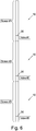
- Figure 1a shows a simplified section of a wellbore 100 that has been drilled into or through rock formation having a reservoir 130.
- a hydrocarbon reservoir e.g. an oil and/or gas field
- the reservoir 130 may equally be subterranean water reservoir (e.g. potable water), or the like.
- Figure 1b shows a plan section of the wellbore of Figure 1a .
- the following embodiments have be described in relation to producing from the reservoir 130, in other words, producing fluid, and in particular oil 120, from the reservoir 130 to the surface (not shown) by known methods.
- further embodiments include injecting fluid into the reservoir 130 from the wellbore 100 (e.g. injecting water to assist with production, and/or hydraulic fracturing fluid, etc.). Given the detailed description below, a skilled person will readily be able to implement those further embodiments.
- the wellbore 100 is essentially defined by a wellbore wall 105.
- the wellbore 100 is cylindrical.
- the reservoir 130 is in a state of compression when in its natural state.
- the effective mean stress e.g. the average stress, less any pore pressure, in the reservoir 130
- any differential stress e.g. the difference between the maximum and minimum stresses.
- any subsequent operations that occur when using fluids 120 at the reservoir 130 have a further effect on these formation forces or stresses in the near-wellbore formation 140.
- the removal of oil 120 from the reservoir 130 creates further stresses that, at some point, cause the formation 140 surrounding the wellbore 100 to begin to yield.
- the introduction of fluids, such as water, from the well to the reservoir can cause yielding.
- near-wellbore formation 140 As that near-wellbore formation 140 yields, it changes from a state of compression, through dilation (e.g. a moderate extension of formation matrix, which may be associated with an increase in porosity) and eventually undergoes a level of compaction (e.g. full or partial collapse of the formation matrix 140).
- the yielding process can cause numerous effects on the formation such as the release of formations fines, the mobilisation of sand , and the near-wellbore formation 140 may start to transmit loads to the wellbore 100 (e.g. equipment, or intermediate apparatus, such as gravel packs, or the like, that may be present in the wellbore 100, including completion equipment, etc.).
- the porosity and permeability of the near-wellbore formation 140 is affected. In the example of removing oil from the wellbore, all of these factors can reduce the ability to operate, and produce from, the reservoir 130.
- the near-wellbore formation 140 can be approximated to be that region of reservoir 130, or formation, which extends at least up to 1.6 times the diameter of the wellbore 100, from the wellbore (i.e. the formation that extends radially for 1.6 times the diameter of the wellbore outwardly from the wall 105 of the wellbore 100).
- the near-wellbore formation 140 may be considered to extend at least up to one tenth of the diameter of the wellbore 100, from the wellbore 100, or at least up to one quarter, or even at least up to one half of the diameter of the wellbore, from the wellbore.
- the near-wellbore formation may be that formation that extends at least up to three times the diameter of the wellbore, from the wellbore.
- Figure 2a shows an exemplary plot 200 of the effective mean stress, P', against the differential stress, Q, that can be present in a near-wellbore formation 140.
- the plot 200 can be considered applicable to a broad range of differing types of formation.
- the stress plot shown Figure 2a is consistent with the teaching from, for example, the paper, " Two-phase damage theory and crustal rock failure: the theoretical 'void' limit, and the prediction of experimental data"; Ricard, Yanick and Bercovici, David; Geophysical Journal International; November 18, 2003; vol. 155; pp 1057-1064 , which is incorporated herein in its entirety.
- the differential stress can provide an indication of the overall difference between stresses in the near-wellbore formation 140.
- Redistribution of these stresses during lifespan of the wellbore for example, due to the effects of reservoir 130 depletion (e.g. reduction in pore pressure) and/or drawdown, can cause an increase in the differential stress at the formation.
- a high differential stress can, in some cases, overcome the strength of the formation matrix.
- the formation 140 will generally have passed from the state of compression 210a, through to dilation 210b, into the state of so-called strong extension/compaction 210c.
- production from the reservoir 130 may be limited because the formation becomes compacted. That is to say that the grains of rock in the near-wellbore formation 140 are compacted together, reducing porosity and permeability.
- particulates of sand may mobilise and/or re-sort, which can ultimately result in a reduction in production. This can also result in wear and tear on components of the production equipment.
- Exemplary data points 220 are shown for a particular reservoir 130, showing the transition of stress in the near-wellbore formation 140 during depletion of the reservoir.
- a boundary 230 between a state of compression 210a and a dilation 210b/extension 210c is shown on Figure 2 .
- the boundary 230 is approximated as a linear relationship between effective mean stress P' and differential stress Q within the near-wellbore formation.
- this may be approximated as roughly 1.18, roughly 1.2, or even 1.
- the ratio of the differential stress Q to the effective mean stress P' exceeds the boundary co-efficient, C boundary , it can be determined that the stress state of the near-wellbore formation 140 is in a state of dilation 210b, or extension 210c. Otherwise, where the ratio of the differential stress Q to the effective mean stress P is less than the boundary co-efficient, C boundary , it can be determined that the stress state of near-wellbore formation 140 is in a state of compression 210a.
- the stress state for each particular near-wellbore formation will vary from reservoir 130 to reservoir 130, due to differing downhole environments at each particular wellbore 100 (e.g. differing rock type, depth, etc.).
- the downhole environment e.g. conditions, properties
- the expected degradation, reduction in porosity and/or permeability of the near-wellbore formation 140 can be determined or estimated for a given depletion from the reservoir 130. This variation in permeability can be predicted, or estimated, from data associated with the wellbore 100.
- This data may be logging data, data associated with experimental activity (e.g. laboratory activity), seismic data, or the like.
- experimental activity e.g. laboratory activity
- seismic data or the like.
- each formation can have an associated porosity-permeability relationship, in which for a given porosity, the permeability (and hence the ability to produce from the reservoir 130) can be related, or estimated.
- porosity-permeability relationships can be determined by experimental means, in a known manner.
- Figure 2b shows an exemplary porosity-permeability plot 250 for a given near-wellbore formation 140.
- the plot 250 shows a plurality of measured data points 255, providing a particular permeability for a particular porosity.
- the near-wellbore formation 140 Due to the nature of rock structure, it might be helpful to maintain, or induce, the near-wellbore formation 140 in a particular stress state (e.g. a state of compression), for example, for as long as possible in order to assist maintaining the permeability. In some cases, it may be helpful to maintain or place the near-wellbore formation 140 in a stress state associated with a state of dilation, because the permeability of the near-wellbore formation 140 may increase in such a state. Furthermore, it may be helpful to avoid a stress state associated with significant compaction, and so avoid sand mobilisation and production. One way in which to achieve this may be to select a formation material (i.e. rock) that shows the least reduction in porosity and/or permeability as the reservoir 130 is depleted.
- a formation material i.e. rock
- the wellbore 100 is essentially cylindrical, the principal stresses ⁇ 1, ⁇ 2 and ⁇ 3 will result in radial and tangential stresses being applied to the wellbore 100, or at least at the wall 105 defining the wellbore 100, or on equipment, such as completion casing, etc., in the wellbore 100.
- ⁇ H is the maximum horizontal stress
- ⁇ h is the minimum horizontal stress
- ⁇ Hh is the shear stress
- ⁇ is the angle around the wellbore 100 being considered.
- Darcy's is an exertive force, which in this case is provided per unit area (i.e. exertive pressure), that is provided from the wellbore 100 - or wall 105 - to the near-wellbore formation 140 (e.g. in addition to any hydrostatic pressure).
- the exertive force may apply a force per unit area (i.e. pressure) greater than about 0.25 MPa, such as greater than 0.5 MPa, or greater than 1 MPa, for example, greater than about 2 MPa, or even greater than 5 MPa.
- the exertive force may provide force per unit area (i.e. pressure) of up to 30 MPa.
- the exertive force may provide a pressure greater than 30 MPa.
- FIG. 2a an example of a near-wellbore formation having a differential stress of 150 MPa, and an effective mean stress of 200 MPa.
- the ratio of the differential stress to effective mean stress is 0.75, which is less that the given boundary co-efficient of 1.1801. Therefore, the formation can be considered to be in a state of compression 210a. In this state, it may be possible to change, or modify, the stress state of the near-wellbore formation 140 from a state of compression to a state of dilation.
- the porosity of the near-wellbore formation 140 can be considered to be a function of firstly the drawdown pressure, DD, and secondly the exertive force, or exertive force per unit area (e.g. exertive pressure, Darcy's) that is applied at the wellbore.
- the permeability of the near-wellbore formation 140 can affect production from the reservoir 130, and that the permeability is a function of the particular conditions and properties of the formation (e.g. rock type, etc.) and the porosity of the near-wellbore formation. Therefore, a preferable porosity, and as such a preferable permeability, can be provided by selecting both the exertive force and the drawdown pressure to apply at the wellbore 100.
- the porosity and/or permeability may be essentially maintained, as the increase in porosity merely offsets any reduction due to production/depletion.
- the stress state of the near-wellbore formation 140 is in a state of compaction (i.e. that the ratio of differential stress to effective mean stress is greater than the boundary co-efficient).
- DD drawdown pressure
- f compaction the compaction coefficient.
- the compaction coefficient is shown as 1, 2 and 4 on Figure 2a at 260d-260f, and can be given from the differential stress and the effective mean stress in a similar manner as above.
- the change in porosity can be determined to be roughly 0.13 (roughly 13%). Using the initial porosity, this provides a final porosity of approximately 0.38 (roughly 38%). Using the associated porosity-permeability relationship, it is possible to determine that this relates to a permeability of approximately 2874 mD. This data point is shown at reference 305 in Figure 3a . The further data points for a particular near-wellbore formation 140 can be determined in a similar manner.
- FIG. 3a shows a similar permeability can be provided when using no exertive force (see the 306 showing a permeability of roughly 2600 mD at a drawdown of around 7.6 MPa (1100 psi) for 0 Pa (0 psi) exertive force per unit area).
- Figure 3b shows a plot 350 corresponding to that shown in Figure 3a , in which the corresponding flow rate in barrels per day (bbl/day) is shown.
- the bbl/day flow rate is roughly 350k (56x10 6 L), whereas at point 308, which corresponds to point 306 in Figure 3b , the bbl/day flow rate in only about 250k (40x10 6 L). This significant difference in available flow rate is as a result of the combination of a particular drawdown pressure for a particular exertive force.
- the exertive force and the drawdown pressure may be selected based on the initial downhole environment associated with the wellbore at the reservoir. However, in some cases, the exertive force and the drawdown pressure may be selected based on the expected downhole environment at one or more times during the life of the wellbore/reservoir. In other words, the exertive force and the drawdown pressure may be selected based on a future downhole environment (e.g. a predicted future stress state after a certain amount of depletion). This may provide improved production over the life of the reservoir 130. This may be useful because there would be little or no need to apply differing, or to modify, the drawdown and exertive forces during the life of the wellbore 100.
- a future downhole environment e.g. a predicted future stress state after a certain amount of depletion
- the exertive force and the drawdown pressure may be selected from time to time, such as periodically (e.g. annually). This modification may be based on a changing downhole environment, for example, changing conditions of the near-wellbore formation 140. In such cases, it may be possible to make assumptions regarding the downhole environment of the wellbore 100 at those intervals in order to select the exertive force and drawdown pressure. In other cases, measurements may be taken in order to determine the downhole environment at the wellbore 100.
- the hydrostatic pressure may also be selected. While, in some examples, the true vertical depth (TVD) of the wellbore may be predetermined, a particular mud may be selected, which may provide a particular hydrostatic pressure, as will be appreciated.
- TVD true vertical depth
- the near-wellbore formation can be considered to be the region extending up to at least a tenth of a diameter of the wellbore into the formation.
- the near-wellbore formation may be considered to be the region extending up to at least a quarter, a half, or even at least one-times the diameter of the wellbore into the formation.
- it has been shown that the near-wellbore formation may be considered to be the region extending up to at least 1.6, or up to at least 1.8 times the diameter of the wellbore.
- any apparatus that is used to apply the exertive force at the wellbore differs from and downhole equipment that merely abuts, or the like, the wellbore, and, for example, does not provide an exertive force for modifying the near-wellbore formation.
- Figure 4a shows a flow diagram 400 of selecting the drawdown pressure and exertive force based on the downhole environment at the wellbore 100.
- the downhole environment at the wellbore 100 is determined, for example, from using logging data, etc. to determine the near-wellbore formation 140 properties, etc.
- an exertive force and corresponding drawdown pressure can be selected based on that initial downhole environment, or based on the expected downhole environment of the wellbore in the future, in the manner described above (e.g. after a certain amount of depletion).
- the exertive force and drawdown pressure is applied, before operating 440, and in this example producing, at the reservoir 130. From time to time, the downhole environment can be reviewed 450 in order to select again the exertive force and drawdown pressure.
- Figure 4b shows similar a flow diagram 500, in which one or both of the drawdown pressure or exertive force is selected based on the downhole environment at the wellbore 100.
- one of the drawdown pressure or exertive force is constrained (e.g. within certain parameters or limits, for example by equipment constraints).
- the downhole environment at the wellbore 100 is again determined, for example, from using logging data, etc. to determine the near-wellbore formation 140 properties, etc.
- an exertive force, or corresponding drawdown pressure is selected based on that initial condition - or expected environment of the wellbore in the future, - in addition to either of the constrained parameters. In other words, in some examples, a useful, or optimal, exertive force or drawdown pressure can be used, even when one of the other is constrained.
- a third step 530 the particular exertive force and drawdown pressure is applied, before operating 540, and gain in this example producing, at the reservoir 130. Again, from time to time, the downhole environment can be reviewed 450 in order to select again the exertive force and/or drawdown pressure.
- Figure 5a shows apparatus 600 for modifying operations at a reservoir, and in this example modifying production from a reservoir.
- the apparatus 600 comprises processor 610, for use with memory 620 (e.g. volatile, non-volatile memory, etc).
- the processor 610 and memory are configured in a known manner.
- the apparatus 600 may be configured with a Digital Signal Processor, Application Specific Integrated Circuit, Field Programmable Gate Array, Programmable Intelligent Computer, microcontroller, or the like.
- the apparatus 100 may be configured with dedicated apparatus.
- the apparatus 600 may be configured with downhole apparatus, such as completion casing, or the like.
- the apparatus 600 may be provided with a personal computer, or handheld device, such as multimedia device or tablet.
- the apparatus is configured to receive data associated with a downhole environment from a downhole database 630.
- the data stored at the downhole database 630 is that used to be able to select a particular exertive force and/or drawdown pressure, as exemplified above.
- the apparatus 600 may be in communication with the downhole database 630 via a wired connection, wireless connection, or combination thereof.
- the apparatus 600 may be in communication with the downhole database 630 via the Internet.
- the database 630 may be comprised with the apparatus 600 (e.g. provided with the memory 620).
- the apparatus further in communication with an output 640.
- the apparatus is configured to receive data associated with one or more particular downhole environments for one or more particular wellbores 100 from a downhole database 630.
- the apparatus is configured to select one or both of an exertive force to apply at a wellbore together with a drawdown pressure at the wellbore, in order to modify production from a reservoir based on the data associated with the or each downhole environment.
- the apparatus 600 is configured to provide the selected exertive force and drawdown pressure to the output 640.
- the output may be display, memory, or the like.
- the output 640 may be in communication with equipment to control production from the wellbore (e.g. downhole equipment, drawdown chokes, etc.). It will be appreciated that in example in which one of the exertive force and drawdown pressure is constrained (e.g. at a particular level), then the apparatus 600 may be configured only to provide the other, non-constrained, parameter.
- the apparatus 600 may be configured to measure, or determine, a downhole environment, in order to provide some or all of the data associated with the downhole environment. This is exemplified by a measurement device 650 in communication with the apparatus 600 by broken lines.
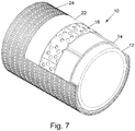
- Figure 5b shows a sectional view of downhole apparatus 20 for applying exertive force to the near-wellbore formation 140.
- the apparatus 20 comprises base pipe for use in lining drilled wellbores 100, such as used when access reservoirs 100.
- the apparatus 20 comprises a rigid base pipe 10 and, in this example, a plurality of non-concentric fluid pressure deformable chambers 12 mounted on the exterior of the pipe 10.
- the pipe 10 may comprise a conventional oil field tubular, which has been modified.
- the chambers 12, six in this instance, are each defined by a tubular member 14.
- the members 14 may initially be formed as cylindrical tubes, flat plates, or the like, which, in some examples, can be formed to provide the shallow oval form as illustrated in Figure 5b .
- the members 14 are also provided with a shallow curvature to match the circumference of the base pipe 10.
- the members 14 are welded to the pipe 10.
- the members 14 are equally spaced around the circumference of the base pipe 10 with a small gap 16 therebetween.
- the members 14 extend axially along the base pipe 10, parallel to the base pipe axis.
- some or all of the chambers may be inflated with fluid in order to provide particular radial pressure to near-wellbore formation 140.
- Figure 5c shows a cross-sectional view of the apparatus 10 within the wellbore.
- the drawdown pressure, DD is illustratively shown as the pressure differential between the static pressure in the reservoir 130 and the pressure in the wellbore 100. This may be considered to be, for example, at a production zone 102. This drawdown pressure causes fluids from the reservoir 130 to flow into the wellbore when the well begins to produce.
- the apparatus 600 shown in Figure 5a is in communication, or comprised with, the apparatus 10 of Figure 5b and Figure 5c .
- a borehole can be drilled into a formation, or subterranean reservoir, to form a wellbore.
- Logging, or other data capture methods can be used to determine the downhole environment at the wellbore. From this data, a particular exertive force and drawdown pressure can be selected using the above described methods.
- Apparatus 20 can be run into the borehole, and deployed in order to provide the particular exertive force, etc. Fluids can then be produced from the wellbore. Subsequently, the exertive force and drawdown pressure may be modifying from time to time, based on the life characteristics of the well.
- the exertive force may be applied from the wellbore to the formation, via intermediate apparatus.
- such intermediate apparatus may include a sand screen, frac-and-pack, gravel pack, etc.
- the exertive force may be applied to the intermediate apparatus, which in turn may or may not transmit through to the formation.
- the selection of exertive force and drawdown pressure may be used to modify the porosity, or the like, of an intermediate apparatus, so as to assist with production and/or injection.
- the intermediate apparatus may be considered to form some or all of the near-wellbore formation. A skilled person will readily be able to implement such further embodiments.
- one or more of the tubular members 14 may be activated to provide an exertive force based on the particular fluids being produced from the wellbore.
- the exertive force may be selected to apply to induce a particular stress state at one region of the wellbore and another particular stress state at another region of the wellbore.
- the apparatus may be configured to selecting a particular exertive force to reduce the production of, for example, water from one region of the wellbore, and additionally/alternatively select an exertive force to assist with production of, for example, oil from another region or the wellbore.
- FIGS 6 to 26 show embodiments and further apparatus 10 that may be used to modify operation at a reservoir, and while may be used in a wellbore 100.
- Figure 6 is a schematic illustration of part of a well-bore completion, which includes three sand screens 10.
- the completion will include many other elements and devices not shown in the drawing, such as a shoe on the leading end of the completion, packers for zonal isolation, hangers, valves and the like.
- a completion will incorporate more than three screens, the number of screens being selected as appropriate.
- Figure 7 of the drawings illustrates a part cutaway view of part of one of the screens of Figure 6 , showing the screen 10 in an initial configuration.
- the screen 10 comprises a base pipe 12 providing mounting for six activation chambers 14 which extend axially along the outer surface of the base pipe 12.
- the chambers 14 are arranged side-by-side around the base pipe 12 and, as will be described, may be inflated or deformed by filling the chambers 14 with high pressure fluid such that the chambers 14 assume an activated configuration as illustrated in Figure 8 of the drawings, as so can be used to apply an exertive force.
- a drainage layer is located externally of the chambers 14, the layer comprising six strips 18 of apertured steel sheet. Like the chambers 14, the strips 18 are arranged side-by-side and extend axially along the screen 10, but are circumferentially offset relative to the chambers 14, as illustrated in the drawings, such that when the chambers 14 are extended the strips 18 bridge the gaps 20 formed between the chambers 14. Further detail relating to the drainage layer will be provided below.
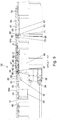
- Figures 9 , 10 , 11 and 12 of the drawings are sectional view of a valve arrangement 30 of one of the screens 10 of Figure 6 , showing the valve arrangement in first, second, third and fourth configurations respectively.
- a valve arrangement 30 will be provided at the lower end of each screen 10 between the lower end of the activation chambers 14 and a stub acme connection 32 and a premium connection (not shown) at the end of the screen 10.
- Figures 9 , 10 , 11 and 12 omit the drainage layer 16, weave 22 and shroud 24.
- the valve arrangement 30 comprises a body 34 comprising a number of interconnected cylindrical portions 34a, 34b which also form the lower end of the screen body. As will be described, the valve arrangement 30 also includes a number of generally cylindrical internal parts which are configurable to control passage of fluid through first and second ports 36, 38 in the body portion 34a.
- the first ports 36 provide communication with the activation chambers 14 via respective chamber blocks 40 which each incorporate a check valve 42 including a ball 44.
- the ball 44 may be formed of any suitable material, for example PTFE, ceramic, steel, rubber, brass or aluminium.
- the second ports 38 also extend through the body portion 34a and, when open, allow production fluid to flow from the exterior of the screen 10 into the base pipe 12, and subsequently to surface.
- the second ports 38 may be dimensioned or otherwise configured to provide a predetermined pressure drop in production fluid flowing into the base pipe. Thus, over the length of the completion the operator may configure the second ports to provide a desired flow profile taking account of local formation conditions.
- each second port 38 is provided with an inflow control device (ICD) assembly in the form of a disc 39 for location in the port 38, the disc having a central flow port accommodating an appropriately sized tungsten carbide insert 41, as illustrated in Figures 9a and 9b of the drawings (the skilled person will note that the ports 38 as illustrated in the figures are non-circular, and thus ICDs in the form of discs 39 are intended for use in combination with an alternative embodiment featuring circular second ports).
- ICD inflow control device
- the insert 41 is selected to provide the desired flow area or pressure drop and is pressed into the disc 39, which is then screwed into the port 38 from the outside of the body portion 34a, the disc outer face being provided with a screw thread configured to engage with a corresponding screw thread provided on the port 38.
- the disc 39 is also provided with an O-ring seal. If appropriate, some ports 38 of a valve arrangement 30 may be fitted with a disc including a blank insert, preventing flow through selected ports.
- the valve arrangement 30 includes a primary valve sleeve 46.
- a central part of the sleeve 46 defines production ports 48 which, when the valve arrangement 30 is in the third configuration, are aligned with the second ports 38.
- the production ports 48 are offset from the second ports 38, and isolated from the exterior of the valve sleeve 46 by seals 50, 51.
- a further seal 52 also serves to isolate the second port 38.
- the lower part of the valve sleeve 46 defines an internal profile 55 for engaging an intervention tool, as will be described.
- the upper end of the sleeve 46 includes collet fingers 49 which have outer profiles for engaging with locating recesses 45 formed in the inner diameter of the body 34.
- the collet fingers 49 also define profiles 43 which allow for mechanical engagement with an intervention tool if required, as will be described.
- a secondary valve or shuttle sleeve 47 is located externally of the primary valve sleeve 46 and carries external seals 54 for isolation of the first port 36 when the valve arrangement is in the third and fourth configurations, as illustrated in Figures 11 and 12 .
- the sleeves 46, 47 are initially fixed together by shear pins 59.
- the shuttle sleeve 47 is located downwards and clear of the first ports 36, and activation ports 56 in the primary valve sleeve 46, which may include a filter member 57, are aligned with the first ports 36, providing for fluid communication between the interior of the screen 10 and the activation chambers 14.
- a valve actuating sleeve 58 is also located within the body 34 and features an external shoulder 60 which provides a sealing contact with the body portion 34b.
- Shear pins 62 initially lock the sleeve 58 relative to the sleeve body against the action of a compression spring 63 contained in a chamber 67 between the sleeve 58 and the body portion 34b. While the upper face of the shoulder 60 is exposed to internal or pipe pressure, the lower face of the shoulder 60 is exposed to external or annulus pressure via a port 61 in the sleeve body, such that the shoulder 60 acts as a differential piston.
- check valves 65 extend through the shoulder 60, allowing fluid to bleed from the chamber between the sleeve 58 and the body portion 34b and into the valve, thus relieving any excess reverse pressure.
- a schematic of a check valve 65 is shown in Figure 9c of the drawings. Accordingly if, for example, during installation or retrieval of the completion, fluid is being circulated down through the completion and up the surrounding annulus, there may be circumstances in which the annulus pressure (P1) rises above the internal pressure (P3).
- fluid from the annulus may bleed through the port 61 and into the spring chamber 67, undergoing a pressure drop to a lower pressure (P2) in the process.
- P2 a pressure drop to a lower pressure
- the remaining pressure differential between the chamber 67 and the interior of the completion may then lift the check valve ball 69 off its seat 71, against the action of a spring 73, allowing the fluid to bleed from the chamber 67 and into the completion.
- the number and configuration of check valves 65 may be selected as appropriate to the completion configuration and anticipated operating conditions.
- An upper end of the sleeve 58 extends externally of the lower end of the primary valve sleeve 46, and abuts the lower end of the shuttle sleeve 47.
- the activation ports 56 are aligned with the first ports 36, while the second ports 38 are closed due to the misalignment between the ports 38 and the production ports 48; the screens 10 are run in hole in this configuration.
- a positive pressure differential between the interior of the screens 10 and the chambers 14 will open the check valve 42 and allow fluid to flow from the interior of the completion into the activation chambers 14, via the chamber blocks 40.
- the chambers 14 will undergo an initial degree of inflation or deformation with the valve arrangement 30 in this first configuration.
- the pipe pressure may be held at this first pressure for a period to provide an initial degree of inflation of the chambers 14.
- an operator may run a wash pipe or the like inside the completion to communicate pressure from surface to the screens 10.
- the internal pipe pressure may be increased to a higher second level to bring the differential pressure experienced across the shoulder 60 to a level sufficient level to shear the pins 62, as illustrated in Figure 4c.
- This pressure differential causes the check valve balls 69 to seat, ensuring the check valves 65 remain closed.
- this movement is not transferred to the primary valve sleeve 46, or the shuttle sleeve 47.
- the first port 36 remains open while the higher second pressure fully inflates and activates the chambers 14.
- valve sleeves 46, 47 do not move to the third configuration when pressure is bled off, and intervention tool may be employed to engage the collet profile 43 and mechanically shift the sleeves 46, 47 upwards.
- intervention tool may be employed to engage the collet profile 43 and mechanically shift the sleeves 46, 47 upwards.
- a mechanical intervention tool may be run into the bore to engage the sleeve profile 55.
- the primary valve sleeve 46 may thus be pushed downwards, dislodging the collet fingers 49 from the upper recess 45b to the lower recess 45a, such that the ports 38, 48 are moved out of alignment, as illustrated in Figure 12 of the drawings.
- the cut metal edges which define the lower spigot 72a are welded to leave an opening for passage of fluid, while the upper spigot 72b is welded closed.
- the opening 74 on the lower spigot 72a is of a width w, less than the chamber width W.
- the edges defining the transition from the full width chamber to the spigots 72 are radiused, in particular being formed with an outer radius 76 and an inner radius 78.
- the outer radius 76 reduces the stresses at the end of the chambers 14, reduces the shrinkage in length during activation, reduces the potential for damaging the weave 22, and smoothes out the end profile of the deformed chamber 14.
- the inner radius 78 reduces stresses in the transition area during activation.
- the open spigot 72a allows for fluid communication between the activation chamber 14 and the interior of the completion, via the chamber block 40 which includes an opening 80 in an end face to receive the spigot 72a.
- the spigot 72a and chamber block 40 are assembled while separated from the screen body, and the components are then bonded together around the complete perimeter of the opening 80 to provide pressure integrity, the bond 82 being perhaps most clearly visible in Figure 16 of the drawings.
- the bond 82 may be provided by any suitable method, typically welding, for example TIG, laser or robotic welding.
- a drilled hole 84 ( Figure 12 ) which extends to intercept a radial recess 85 which accommodates the check valve 42.
- the chamber blocks 40 are retained in place on the screen body 34a by clamps 88 ( Figure 12 ) which are bolted to the body 34a and engage with shoulders 90 formed on the edges of the blocks 40.
- drainage strips 18 are mounted externally of the mounted chambers 14, and parts of a drainage layer strip 18 are illustrated in Figure 17a and 17b of the drawings.
- the drainage layer formed by the strips 18 lifts the weave 22 from the activating chambers 14, maximising inflow through and around the screen.
- the strips 18 are of solid steel plate provided with perforations 92 which allow oil or gas to flow through weave 22 and into the screen 10.
- the strips are produced by punching and embossing flat plate to provide the required pattern, before roll forming to the required radius and then cutting to length.
- the perforations 92 may be any appropriate shape or size, and in the illustrated embodiment each strip 18 includes four axial rows of round holes.
- the strips 18 are also embossed to form protrusions on the inner surface of the strips 18, to lift the drainage layer up from the activation chambers 14 to permit flow under the layer and between the activating chambers 14 and the strips 18.
- the embosses 94 may be any appropriate shape, size or depth, and in the illustrated embodiment the embosses 94 are formed as four axial rows, axially and circumferentially offset from the perforations 92.
- the strips 18 are formed with an inner radius to match the outer radius of the activation chambers 14 to ensure that the outer diameter of the screen 10 is minimised and that the drainage layer formed by the strips 18 provides optimum support across the activation chambers 14.
- the ends of the strips 18 are tapered and are secured on the screen 10 by welding to shoulders 91 ( Figure 12 ) provided on the chamber block clamps 88.
- the strip ends are also slotted to facilitate deformation; the strip ends must bend and extend to accommodate the activation of the chambers 14.
- the drainage layer strips 18 provide support to the weave 22 as the gaps 20 ( Figure 8 ) between the activation chambers 14 increases. Also, the radiused strips 18 assist in maintaining a substantially circular shape during the activation process. In the absence of such support, the screen would assume a hexagonal shape due to the weave 22 and the outer shroud 24 forming straight lines between each activation chamber outer diameter.
- FIG. 18 of the drawings illustrates a clamp arrangement for use in securing the weave 22 in place on the screen 10.
- the Figure shows the body portion 34a which serves as a clamp body and a retainer ring 96 which may be threaded to the body 34a.
- the clamp body 34a defines a recess 93 upwards of the thread 97, and a tapering surface 98 leading down into the recess 100.
- the ring 96 includes a corresponding tapering surface 102 on its upper end, such that when the ring 96 is tightened on the body 34a the surfaces 98, 102 come together and clamp a portion of the weave 22 therebetween.
- the weave 22 is wrapped around the screen body, over the drainage layer formed by the strips 18, with the upper and lower ends of the weave 22 positioned in the recesses 93 (a similar clamping arrangement is provided at the upper end of the screen).
- the weave 22 may be held in place using rachet straps, spot welding or the like, and if desired the weave 22 may be spot welded in the recess 93. Spot welds may also be provided along the length of the screen 10, to secure the weave 22 to the strips 18.
- the clamping ring 96 is then screwed on to the clamp body 34a and the taper surfaces 98, 102 clamp and secure the weave 22.
- the shroud 24 is then located over the clamped weave 22.
- the shroud 24 will form the outer surface of the screen.
- a portion of the screen may be covered with an elastomer, as illustrated in Figures 21 and 22 of the drawings.
- a neoprene elastomer coating 104 has been wrapped around a portion of the screen outside diameter. Once such a screen has been activated, the rubber coating 104 will be pushed out against the surrounding casing or formation and will provide a restriction or baffle to the flow of production fluids between zones; the coating 104 may provide a low pressure seal or a restriction to flow of fluid past the screen, but may permit fluid to flow beneath the coating 104 and into or along the screen.
- different qualities of material may be utilised to provide a higher pressure seal.
- the pressure increases in the chambers on the other side of the structure: for example, if a high load is applied in the region of the chamber 14(6), an elevated pressure is measured in the opposite chamber 14(3), and to a lesser extent in adjacent chambers 14(4) and 14(2). Testing has further demonstrated that the chambers 14 tend to absorb at least initial deformation of the structure, such that the internal diameter of the base pipe 12 remains substantially unobstructed. Also, the deformed chambers 14 tend to recover, typically by around 50%, when the applied force is reduced.
- sand integrity of sand screens incorporating inflated chambers 14 as described herein when subject to crush or pinch loads was maintained at very high loading, as was the integrity of the chambers 14.
- the pressure in the chambers 14 increased from an initial 6.9 MPa (1000 psi) to almost 8.3 MPa (1200 psi), corresponding to a 2.5 cm (1 inch) deformation of a sand screen with an activated outer diameter of 22 cm (8 1 ⁇ 2 inches).
- a sand screen in accordance with an embodiment of the present invention will withstand significant crush loading, for example from a swelling or partially collapsing formation, and will accommodate a degree of deformation without adversely affecting the base pipe 12.
- inflatable chambers may be mounted on an impervious section of a completion intended to intersect a non-producing problem formation. Accordingly, an operator may be able to utilise significantly lighter and less expensive base pipe 12, and may be able to drill and then maintain bores through difficult formations, for example swelling formations which would otherwise be expected to crush bore lining tubing located in the bores.
- near-wellbore formation 140 problems such as reduction in permeability and mobilisation have been addressed, by applying an exertive force to the near wellbore formation 140 and, additionally, using an appropriate drawdown pressure, based on the exertive force.
- Such an exertive force essentially re-stresses the formation 140 at the wellbore wall 105.
- This process prevents solids from re-sorting and thus maintains formation permeability.
- the process and apparatus can be effectively use for sand control at a wellbore, for example, using an exertive force together with a drawdown pressure in order to inhibit, reduce or mitigate sand mobilisation at a wellbore, or even in some cases increase sand mobilisation.
- This method and apparatus allows for greater drawdowns to be placed on a reservoir 130 and can increase productivity.
- the same method and/or apparatus can be used to inject to a subterranean formation (without necessarily being a reservoir), and modifying the formation in order to assist with that injection.
- the drawdown pressure may be considered to be a negative drawdown pressure (or so-called injection pressure), causing fluid to flow from the wellbore to the formation.
- injection pressure or so-called injection pressure
- the same methods and apparatus may be used to produce and inject at a particular wellbore.
- These computer program instructions may also be stored in a computer-readable medium that can direct a computer or other programmable data processing apparatus to function in a particular manner, such that the instructions stored in the computer-readable medium produce an article of manufacture including instructions which implement the functions/acts specified in the block diagrams and/or flowchart block or blocks.
- a tangible, non-transitory computer-readable medium may include an electronic, magnetic, optical, electromagnetic, or semiconductor data storage system, apparatus, or device. More specific examples of the computer-readable medium would include the following: a portable computer diskette, a random access memory (RAM) circuit, a read-only memory (ROM) circuit, an erasable programmable read-only memory (EPROM or Flash memory) circuit, a portable compact disc read-only memory (CD-ROM), and a portable digital video disc read-only memory (DVD/Blu-ray).
- RAM random access memory
- ROM read-only memory
- EPROM or Flash memory erasable programmable read-only memory
- CD-ROM compact disc read-only memory
- DVD/Blu-ray portable digital video disc read-only memory
- the computer program instructions may also be loaded onto a computer and/or other programmable data processing apparatus to cause a series of operational steps to be performed on the computer and/or other programmable apparatus to produce a computer-implemented process such that the instructions which execute on the computer or other programmable apparatus provide steps for implementing the functions/acts specified in the block diagrams and/or flowchart block or blocks.
- the invention may be embodied in hardware and/or in software (including firmware, resident software, micro-code, etc.) that runs on a processor, which may collectively be referred to as "circuitry,” "a module” or variants thereof.
Claims (17)
- Procédé de modification d'opérations au niveau d'une formation souterraine, comprenant :la détermination (410, 510) de l'environnement de fond de trou au niveau d'un puits de forage dans une formation souterraine, à l'aide d'au moins un processeur ;la sélection (420, 520) d'une force d'effort à appliquer au niveau d'un puits de forage (100) avec une pression de soutirage au niveau du puits de forage afin de modifier les opérations au niveau de la formation souterraine, la sélection de l'une ou des deux de la force d'effort et de la pression de soutirage à l'aide de l'au moins un processeur et étant basé sur l'environnement de fond de trou au niveau du puits de forage ; etl'application (430, 530) de la force d'effort et de la pression de soutirage sélectionnées au niveau du puits de forage, à l'aide d'un appareil de fond de trou.
- Procédé selon la revendication 1, dans lequel l'une de la force d'effort et de la pression de soutirage est contrainte, de sorte que la sélection à la fois de la force d'effort avec une pression de soutirage est basée sur l'utilisation d'une force d'effort contrainte ou d'une pression de soutirage contrainte.
- Procédé selon la revendication 1 ou la revendication 2, comprenant en outre la sélection d'une pression hydrostatique au niveau du puits de forage afin de modifier les opérations au niveau de la formation.
- Procédé selon la revendication 1, 2 ou 3, dans lequel l'environnement de fond de trou comprend une porosité d'une formation proche du puits de forage, la formation proche du puits de forage étant la région de formation entourant radialement le puits de forage dans la formation.
- Procédé selon la revendication 4, dans lequel la formation proche du puits de forage s'étend au moins jusqu'à 1,6 fois le diamètre du puits de forage dans la formation entourant tout ou une partie du puits de forage.
- Procédé selon la revendication 4 ou 5, dans lequel la force d'effort et la pression de soutirage sont sélectionnées afin de modifier la porosité et/ou la perméabilité de la formation proche du puits de forage.
- Procédé selon la revendication 4, 5 ou 6, dans lequel la force d'effort et la pression de soutirage sont sélectionnées afin de maintenir ou de réduire le taux de changement de la porosité et/ou de la perméabilité de la formation proche du puits de forage lors d'opérations au niveau de la formation souterraine.
- Procédé selon l'une quelconque des revendications 1 à 7, dans lequel la force d'effort est destinée à être appliquée du puits de forage à la formation proche du puits de forage par l'intermédiaire d'un appareil intermédiaire, positionné au niveau du puits de forage.
- Procédé selon l'une quelconque des revendications 1 à 8, dans lequel la force d'effort est sélectionnée afin de fournir ou d'induire un état de contrainte particulier, tel que la dilatation, dans la formation ou la formation proche du puits de forage.
- Procédé selon l'une quelconque des revendications 1 à 9, dans lequel la force d'effort est fournie sous la forme d'une force par surface d'unité d'une paroi définissant le puits de forage.
- Procédé selon l'une quelconque des revendications 1 à 10, dans lequel l'opération de la formation comprend la modification de la production à partir d'un réservoir, telle que son augmentation.
- Procédé selon l'une quelconque des revendications 1 à 11, dans lequel la force d'effort avec une pression de soutirage est sélectionnée afin d'inhiber, de réduire ou d'atténuer la mobilisation de sable au niveau d'un puits de forage.
- Appareil de modification des opérations au niveau d'une formation souterraine, l'appareil comprenant au moins un processeur, et étant configuré pour sélectionner à la fois une force d'effort à appliquer au niveau d'un puits de forage avec une pression de soutirage au niveau du puits de forage, afin de modifier les opérations au niveau d'un réservoir, l'appareil étant configuré pour baser la sélection de la force d'effort et de la pression de soutirage sur un environnement de fond de trou particulier au niveau du puits de forage ; l'appareil comprenant en outre un appareil de fond de trou pour appliquer la force d'effort et la pression de soutirage sélectionnées au niveau du puits de forage.
- Appareil selon la revendication 13, configuré pour modifier au moins l'une des opérations de production à partir d'un réservoir et/ou d'injection au niveau de la formation.
- Appareil selon l'une quelconque des revendications 13 à 14, dans lequel l'appareil comprend un filtre à sable, tel qu'un tissage.
- Programme d'ordinateur comprenant des instructions pour amener l'appareil selon la revendication 13 ou la revendication 14 à effectuer les étapes :de détermination (410, 510) de l'environnement de fond de trou au niveau d'un puits de forage dans une formation souterraine ;de sélection (420, 520) d'une force d'effort à appliquer au niveau d'un puits de forage (100) avec une pression de soutirage au niveau du puits de forage afin de modifier les opérations au niveau de la formation souterraine, la sélection de l'une ou des deux de la force d'effort et de la pression de soutirage étant basée sur l'environnement de fond de trou au niveau du puits de forage ;dans lequel le programme informatique est configuré pour être utilisé avec un appareil de fond de trou afin d'appliquer (430, 530) la force d'effort sélectionnée et la pression de soutirage au niveau du puits de forage, pour modifier les opérations au niveau d'une formation souterraine.
- Support lisible par ordinateur sur lequel est stocké le programme d'ordinateur selon la revendication 16.
Applications Claiming Priority (2)
| Application Number | Priority Date | Filing Date | Title |
|---|---|---|---|
| GBGB1210532.6A GB201210532D0 (en) | 2012-06-14 | 2012-06-14 | Subterranean formation methods and apparatus |
| PCT/GB2013/051558 WO2013186569A2 (fr) | 2012-06-14 | 2013-06-14 | Procédés et appareil de formation souterraine |
Publications (2)
| Publication Number | Publication Date |
|---|---|
| EP2882929A2 EP2882929A2 (fr) | 2015-06-17 |
| EP2882929B1 true EP2882929B1 (fr) | 2019-10-02 |
Family
ID=46605938
Family Applications (1)
| Application Number | Title | Priority Date | Filing Date |
|---|---|---|---|
| EP13730060.4A Active EP2882929B1 (fr) | 2012-06-14 | 2013-06-14 | Procédés et appareil de formation souterraine |
Country Status (4)
| Country | Link |
|---|---|
| US (1) | US10428631B2 (fr) |
| EP (1) | EP2882929B1 (fr) |
| GB (1) | GB201210532D0 (fr) |
| WO (1) | WO2013186569A2 (fr) |
Families Citing this family (13)
| Publication number | Priority date | Publication date | Assignee | Title |
|---|---|---|---|---|
| EP2631423A1 (fr) | 2012-02-23 | 2013-08-28 | Services Pétroliers Schlumberger | Procédé et appareil d'écran |
| GB201323121D0 (en) | 2013-12-30 | 2014-02-12 | Darcy Technologies Ltd | Downhole Apparatus |
| GB201323127D0 (en) | 2013-12-30 | 2014-02-12 | Darcy Technologies Ltd | Downhole apparatus |
| US9695675B2 (en) * | 2014-01-03 | 2017-07-04 | Weatherford Technology Holdings, Llc | High-rate injection screen assembly with checkable ports |
| WO2016076853A1 (fr) * | 2014-11-12 | 2016-05-19 | Halliburton Energy Services, Inc. | Support à haute expansion en treillis en interne pour applications d'étanchéité de dispositif de commande d'écoulement entrant |
| US10781672B2 (en) | 2016-06-15 | 2020-09-22 | Chevron U.S.A. Inc. | Protective shrouds for sand control screen assemblies |
| US10767449B2 (en) | 2016-06-15 | 2020-09-08 | Chevron U.S.A. Inc. | Protective shrouds for sand control screen assemblies |
| US10450844B2 (en) * | 2016-06-15 | 2019-10-22 | Chevron U.S.A. Inc. | Drainage layers for sand control screen assemblies |
| CN107766689B (zh) * | 2016-08-17 | 2021-03-23 | 中国石油化工股份有限公司 | 开发动态约束的储层渗透率时变模型的建立方法 |
| CN109236186B (zh) * | 2018-10-30 | 2020-03-06 | 中国石油大学(华东) | 钻井套管及大井眼多分支井快速钻完井方法 |
| US11326448B2 (en) | 2019-12-04 | 2022-05-10 | Saudi Arabian Oil Company | Pressure testing systems for subterranean rock formations |
| US11591905B2 (en) * | 2020-05-21 | 2023-02-28 | Saudi Arabian Oil Company | Methods and systems for determining optimum pressure drawdown in a production well for a shale gas reservoir |
| US11619127B1 (en) | 2021-12-06 | 2023-04-04 | Saudi Arabian Oil Company | Wellhead acoustic insulation to monitor hydraulic fracturing |
Family Cites Families (4)
| Publication number | Priority date | Publication date | Assignee | Title |
|---|---|---|---|---|
| GB0712345D0 (en) * | 2007-06-26 | 2007-08-01 | Metcalfe Paul D | Downhole apparatus |
| US7653488B2 (en) * | 2007-08-23 | 2010-01-26 | Schlumberger Technology Corporation | Determination of point of sand production initiation in wellbores using residual deformation characteristics and real time monitoring of sand production |
| GB201019358D0 (en) * | 2010-11-16 | 2010-12-29 | Darcy Technologies Ltd | Downhole method and apparatus |
| CA2757125C (fr) * | 2011-08-05 | 2014-03-25 | Cenovus Fccl Ltd., As Operator For Fccl Partnership | Creation d'un lien entre deux puits dans un reservoir de sables bitumineux grace a une dilatation obtenue par une circulation de vapeur ou d'eau a pression elevee |
-
2012
- 2012-06-14 GB GBGB1210532.6A patent/GB201210532D0/en not_active Ceased
-
2013
- 2013-06-14 EP EP13730060.4A patent/EP2882929B1/fr active Active
- 2013-06-14 WO PCT/GB2013/051558 patent/WO2013186569A2/fr active Application Filing
- 2013-06-14 US US14/407,475 patent/US10428631B2/en active Active
Non-Patent Citations (1)
| Title |
|---|
| None * |
Also Published As
| Publication number | Publication date |
|---|---|
| WO2013186569A2 (fr) | 2013-12-19 |
| US10428631B2 (en) | 2019-10-01 |
| GB201210532D0 (en) | 2012-07-25 |
| EP2882929A2 (fr) | 2015-06-17 |
| US20150144330A1 (en) | 2015-05-28 |
| WO2013186569A3 (fr) | 2014-09-18 |
Similar Documents
| Publication | Publication Date | Title |
|---|---|---|
| EP2882929B1 (fr) | Procédés et appareil de formation souterraine | |
| AU2017265078B2 (en) | Downhole apparatus | |
| US8479810B2 (en) | Downhole apparatus | |
| CA2811268C (fr) | Methode et systeme de dilatation de mandrins sous des obstacles | |
| US10689926B2 (en) | Lost circulation zone isolating liner | |
| CA3076393C (fr) | Appareil de fond de trou | |
| CA2694822A1 (fr) | Procede pour modifier l'etat de contrainte d'une formation et/ou d'un element tubulaire |
Legal Events
| Date | Code | Title | Description |
|---|---|---|---|
| PUAI | Public reference made under article 153(3) epc to a published international application that has entered the european phase |
Free format text: ORIGINAL CODE: 0009012 |
|
| 17P | Request for examination filed |
Effective date: 20150112 |
|
| AK | Designated contracting states |
Kind code of ref document: A2 Designated state(s): AL AT BE BG CH CY CZ DE DK EE ES FI FR GB GR HR HU IE IS IT LI LT LU LV MC MK MT NL NO PL PT RO RS SE SI SK SM TR |
|
| AX | Request for extension of the european patent |
Extension state: BA ME |
|
| DAX | Request for extension of the european patent (deleted) | ||
| STAA | Information on the status of an ep patent application or granted ep patent |
Free format text: STATUS: EXAMINATION IS IN PROGRESS |
|
| 17Q | First examination report despatched |
Effective date: 20170103 |
|
| RAP1 | Party data changed (applicant data changed or rights of an application transferred) |
Owner name: HALLIBURTON MANUFACTURING AND SERVICES LIMITED |
|
| GRAP | Despatch of communication of intention to grant a patent |
Free format text: ORIGINAL CODE: EPIDOSNIGR1 |
|
| STAA | Information on the status of an ep patent application or granted ep patent |
Free format text: STATUS: GRANT OF PATENT IS INTENDED |
|
| INTG | Intention to grant announced |
Effective date: 20190228 |
|
| RIN1 | Information on inventor provided before grant (corrected) |
Inventor name: NOBLETT, DAVID ALLAN Inventor name: BRUCE, STEPHEN EDMUND Inventor name: KENT, STEPHEN Inventor name: MCCANN, DOMINIC PATRICK JOSEPH |
|
| GRAJ | Information related to disapproval of communication of intention to grant by the applicant or resumption of examination proceedings by the epo deleted |
Free format text: ORIGINAL CODE: EPIDOSDIGR1 |
|
| STAA | Information on the status of an ep patent application or granted ep patent |
Free format text: STATUS: EXAMINATION IS IN PROGRESS |
|
| GRAP | Despatch of communication of intention to grant a patent |
Free format text: ORIGINAL CODE: EPIDOSNIGR1 |
|
| STAA | Information on the status of an ep patent application or granted ep patent |
Free format text: STATUS: GRANT OF PATENT IS INTENDED |
|
| INTC | Intention to grant announced (deleted) | ||
| INTG | Intention to grant announced |
Effective date: 20190716 |
|
| GRAS | Grant fee paid |
Free format text: ORIGINAL CODE: EPIDOSNIGR3 |
|
| GRAA | (expected) grant |
Free format text: ORIGINAL CODE: 0009210 |
|
| STAA | Information on the status of an ep patent application or granted ep patent |
Free format text: STATUS: THE PATENT HAS BEEN GRANTED |
|
| AK | Designated contracting states |
Kind code of ref document: B1 Designated state(s): AL AT BE BG CH CY CZ DE DK EE ES FI FR GB GR HR HU IE IS IT LI LT LU LV MC MK MT NL NO PL PT RO RS SE SI SK SM TR |
|
| REG | Reference to a national code |
Ref country code: GB Ref legal event code: FG4D |
|
| REG | Reference to a national code |
Ref country code: CH Ref legal event code: EP Ref country code: AT Ref legal event code: REF Ref document number: 1186365 Country of ref document: AT Kind code of ref document: T Effective date: 20191015 |
|
| REG | Reference to a national code |
Ref country code: DE Ref legal event code: R096 Ref document number: 602013061219 Country of ref document: DE |
|
| REG | Reference to a national code |
Ref country code: IE Ref legal event code: FG4D |
|
| REG | Reference to a national code |
Ref country code: NO Ref legal event code: T2 Effective date: 20191002 |
|
| REG | Reference to a national code |
Ref country code: NL Ref legal event code: MP Effective date: 20191002 |
|
| REG | Reference to a national code |
Ref country code: LT Ref legal event code: MG4D |
|
| REG | Reference to a national code |
Ref country code: AT Ref legal event code: MK05 Ref document number: 1186365 Country of ref document: AT Kind code of ref document: T Effective date: 20191002 |
|
| PG25 | Lapsed in a contracting state [announced via postgrant information from national office to epo] |
Ref country code: FI Free format text: LAPSE BECAUSE OF FAILURE TO SUBMIT A TRANSLATION OF THE DESCRIPTION OR TO PAY THE FEE WITHIN THE PRESCRIBED TIME-LIMIT Effective date: 20191002 Ref country code: BG Free format text: LAPSE BECAUSE OF FAILURE TO SUBMIT A TRANSLATION OF THE DESCRIPTION OR TO PAY THE FEE WITHIN THE PRESCRIBED TIME-LIMIT Effective date: 20200102 Ref country code: PT Free format text: LAPSE BECAUSE OF FAILURE TO SUBMIT A TRANSLATION OF THE DESCRIPTION OR TO PAY THE FEE WITHIN THE PRESCRIBED TIME-LIMIT Effective date: 20200203 Ref country code: AT Free format text: LAPSE BECAUSE OF FAILURE TO SUBMIT A TRANSLATION OF THE DESCRIPTION OR TO PAY THE FEE WITHIN THE PRESCRIBED TIME-LIMIT Effective date: 20191002 Ref country code: LT Free format text: LAPSE BECAUSE OF FAILURE TO SUBMIT A TRANSLATION OF THE DESCRIPTION OR TO PAY THE FEE WITHIN THE PRESCRIBED TIME-LIMIT Effective date: 20191002 Ref country code: LV Free format text: LAPSE BECAUSE OF FAILURE TO SUBMIT A TRANSLATION OF THE DESCRIPTION OR TO PAY THE FEE WITHIN THE PRESCRIBED TIME-LIMIT Effective date: 20191002 Ref country code: NL Free format text: LAPSE BECAUSE OF FAILURE TO SUBMIT A TRANSLATION OF THE DESCRIPTION OR TO PAY THE FEE WITHIN THE PRESCRIBED TIME-LIMIT Effective date: 20191002 Ref country code: SE Free format text: LAPSE BECAUSE OF FAILURE TO SUBMIT A TRANSLATION OF THE DESCRIPTION OR TO PAY THE FEE WITHIN THE PRESCRIBED TIME-LIMIT Effective date: 20191002 Ref country code: ES Free format text: LAPSE BECAUSE OF FAILURE TO SUBMIT A TRANSLATION OF THE DESCRIPTION OR TO PAY THE FEE WITHIN THE PRESCRIBED TIME-LIMIT Effective date: 20191002 Ref country code: PL Free format text: LAPSE BECAUSE OF FAILURE TO SUBMIT A TRANSLATION OF THE DESCRIPTION OR TO PAY THE FEE WITHIN THE PRESCRIBED TIME-LIMIT Effective date: 20191002 Ref country code: GR Free format text: LAPSE BECAUSE OF FAILURE TO SUBMIT A TRANSLATION OF THE DESCRIPTION OR TO PAY THE FEE WITHIN THE PRESCRIBED TIME-LIMIT Effective date: 20200103 |
|
| PG25 | Lapsed in a contracting state [announced via postgrant information from national office to epo] |
Ref country code: HR Free format text: LAPSE BECAUSE OF FAILURE TO SUBMIT A TRANSLATION OF THE DESCRIPTION OR TO PAY THE FEE WITHIN THE PRESCRIBED TIME-LIMIT Effective date: 20191002 Ref country code: RS Free format text: LAPSE BECAUSE OF FAILURE TO SUBMIT A TRANSLATION OF THE DESCRIPTION OR TO PAY THE FEE WITHIN THE PRESCRIBED TIME-LIMIT Effective date: 20191002 Ref country code: CZ Free format text: LAPSE BECAUSE OF FAILURE TO SUBMIT A TRANSLATION OF THE DESCRIPTION OR TO PAY THE FEE WITHIN THE PRESCRIBED TIME-LIMIT Effective date: 20191002 Ref country code: IS Free format text: LAPSE BECAUSE OF FAILURE TO SUBMIT A TRANSLATION OF THE DESCRIPTION OR TO PAY THE FEE WITHIN THE PRESCRIBED TIME-LIMIT Effective date: 20200224 |
|
| PG25 | Lapsed in a contracting state [announced via postgrant information from national office to epo] |
Ref country code: AL Free format text: LAPSE BECAUSE OF FAILURE TO SUBMIT A TRANSLATION OF THE DESCRIPTION OR TO PAY THE FEE WITHIN THE PRESCRIBED TIME-LIMIT Effective date: 20191002 |
|
| REG | Reference to a national code |
Ref country code: DE Ref legal event code: R097 Ref document number: 602013061219 Country of ref document: DE |
|
| PG2D | Information on lapse in contracting state deleted |
Ref country code: IS |
|
| PG25 | Lapsed in a contracting state [announced via postgrant information from national office to epo] |
Ref country code: EE Free format text: LAPSE BECAUSE OF FAILURE TO SUBMIT A TRANSLATION OF THE DESCRIPTION OR TO PAY THE FEE WITHIN THE PRESCRIBED TIME-LIMIT Effective date: 20191002 Ref country code: RO Free format text: LAPSE BECAUSE OF FAILURE TO SUBMIT A TRANSLATION OF THE DESCRIPTION OR TO PAY THE FEE WITHIN THE PRESCRIBED TIME-LIMIT Effective date: 20191002 Ref country code: DK Free format text: LAPSE BECAUSE OF FAILURE TO SUBMIT A TRANSLATION OF THE DESCRIPTION OR TO PAY THE FEE WITHIN THE PRESCRIBED TIME-LIMIT Effective date: 20191002 Ref country code: IS Free format text: LAPSE BECAUSE OF FAILURE TO SUBMIT A TRANSLATION OF THE DESCRIPTION OR TO PAY THE FEE WITHIN THE PRESCRIBED TIME-LIMIT Effective date: 20200202 |
|
| PLBE | No opposition filed within time limit |
Free format text: ORIGINAL CODE: 0009261 |
|
| STAA | Information on the status of an ep patent application or granted ep patent |
Free format text: STATUS: NO OPPOSITION FILED WITHIN TIME LIMIT |
|
| PG25 | Lapsed in a contracting state [announced via postgrant information from national office to epo] |
Ref country code: IT Free format text: LAPSE BECAUSE OF FAILURE TO SUBMIT A TRANSLATION OF THE DESCRIPTION OR TO PAY THE FEE WITHIN THE PRESCRIBED TIME-LIMIT Effective date: 20191002 Ref country code: SK Free format text: LAPSE BECAUSE OF FAILURE TO SUBMIT A TRANSLATION OF THE DESCRIPTION OR TO PAY THE FEE WITHIN THE PRESCRIBED TIME-LIMIT Effective date: 20191002 Ref country code: SM Free format text: LAPSE BECAUSE OF FAILURE TO SUBMIT A TRANSLATION OF THE DESCRIPTION OR TO PAY THE FEE WITHIN THE PRESCRIBED TIME-LIMIT Effective date: 20191002 |
|
| 26N | No opposition filed |
Effective date: 20200703 |
|
| PG25 | Lapsed in a contracting state [announced via postgrant information from national office to epo] |
Ref country code: SI Free format text: LAPSE BECAUSE OF FAILURE TO SUBMIT A TRANSLATION OF THE DESCRIPTION OR TO PAY THE FEE WITHIN THE PRESCRIBED TIME-LIMIT Effective date: 20191002 |
|
| REG | Reference to a national code |
Ref country code: DE Ref legal event code: R119 Ref document number: 602013061219 Country of ref document: DE |
|
| PG25 | Lapsed in a contracting state [announced via postgrant information from national office to epo] |
Ref country code: MC Free format text: LAPSE BECAUSE OF FAILURE TO SUBMIT A TRANSLATION OF THE DESCRIPTION OR TO PAY THE FEE WITHIN THE PRESCRIBED TIME-LIMIT Effective date: 20191002 |
|
| REG | Reference to a national code |
Ref country code: CH Ref legal event code: PL |
|
| PG25 | Lapsed in a contracting state [announced via postgrant information from national office to epo] |
Ref country code: LU Free format text: LAPSE BECAUSE OF NON-PAYMENT OF DUE FEES Effective date: 20200614 |
|
| REG | Reference to a national code |
Ref country code: BE Ref legal event code: MM Effective date: 20200630 |
|
| PG25 | Lapsed in a contracting state [announced via postgrant information from national office to epo] |
Ref country code: FR Free format text: LAPSE BECAUSE OF NON-PAYMENT OF DUE FEES Effective date: 20200630 Ref country code: LI Free format text: LAPSE BECAUSE OF NON-PAYMENT OF DUE FEES Effective date: 20200630 Ref country code: IE Free format text: LAPSE BECAUSE OF NON-PAYMENT OF DUE FEES Effective date: 20200614 Ref country code: CH Free format text: LAPSE BECAUSE OF NON-PAYMENT OF DUE FEES Effective date: 20200630 |
|
| PG25 | Lapsed in a contracting state [announced via postgrant information from national office to epo] |
Ref country code: DE Free format text: LAPSE BECAUSE OF NON-PAYMENT OF DUE FEES Effective date: 20210101 Ref country code: BE Free format text: LAPSE BECAUSE OF NON-PAYMENT OF DUE FEES Effective date: 20200630 |
|
| PG25 | Lapsed in a contracting state [announced via postgrant information from national office to epo] |
Ref country code: TR Free format text: LAPSE BECAUSE OF FAILURE TO SUBMIT A TRANSLATION OF THE DESCRIPTION OR TO PAY THE FEE WITHIN THE PRESCRIBED TIME-LIMIT Effective date: 20191002 Ref country code: MT Free format text: LAPSE BECAUSE OF FAILURE TO SUBMIT A TRANSLATION OF THE DESCRIPTION OR TO PAY THE FEE WITHIN THE PRESCRIBED TIME-LIMIT Effective date: 20191002 Ref country code: CY Free format text: LAPSE BECAUSE OF FAILURE TO SUBMIT A TRANSLATION OF THE DESCRIPTION OR TO PAY THE FEE WITHIN THE PRESCRIBED TIME-LIMIT Effective date: 20191002 |
|
| PG25 | Lapsed in a contracting state [announced via postgrant information from national office to epo] |
Ref country code: MK Free format text: LAPSE BECAUSE OF FAILURE TO SUBMIT A TRANSLATION OF THE DESCRIPTION OR TO PAY THE FEE WITHIN THE PRESCRIBED TIME-LIMIT Effective date: 20191002 |
|
| PGFP | Annual fee paid to national office [announced via postgrant information from national office to epo] |
Ref country code: NO Payment date: 20230525 Year of fee payment: 11 |
|
| PGFP | Annual fee paid to national office [announced via postgrant information from national office to epo] |
Ref country code: GB Payment date: 20230403 Year of fee payment: 11 |