EP2882257A1 - Expandable routing system (LTE + DSL) - Google Patents
Expandable routing system (LTE + DSL) Download PDFInfo
- Publication number
- EP2882257A1 EP2882257A1 EP13198005.4A EP13198005A EP2882257A1 EP 2882257 A1 EP2882257 A1 EP 2882257A1 EP 13198005 A EP13198005 A EP 13198005A EP 2882257 A1 EP2882257 A1 EP 2882257A1
- Authority
- EP
- European Patent Office
- Prior art keywords
- network
- wireless transceiver
- cable routing
- routing apparatus
- antenna
- Prior art date
- Legal status (The legal status is an assumption and is not a legal conclusion. Google has not performed a legal analysis and makes no representation as to the accuracy of the status listed.)
- Withdrawn
Links
Images


Classifications
-
- H—ELECTRICITY
- H04—ELECTRIC COMMUNICATION TECHNIQUE
- H04W—WIRELESS COMMUNICATION NETWORKS
- H04W88/00—Devices specially adapted for wireless communication networks, e.g. terminals, base stations or access point devices
- H04W88/08—Access point devices
- H04W88/10—Access point devices adapted for operation in multiple networks, e.g. multi-mode access points
-
- H—ELECTRICITY
- H04—ELECTRIC COMMUNICATION TECHNIQUE
- H04W—WIRELESS COMMUNICATION NETWORKS
- H04W84/00—Network topologies
- H04W84/02—Hierarchically pre-organised networks, e.g. paging networks, cellular networks, WLAN [Wireless Local Area Network] or WLL [Wireless Local Loop]
- H04W84/10—Small scale networks; Flat hierarchical networks
- H04W84/12—WLAN [Wireless Local Area Networks]
-
- H—ELECTRICITY
- H04—ELECTRIC COMMUNICATION TECHNIQUE
- H04W—WIRELESS COMMUNICATION NETWORKS
- H04W88/00—Devices specially adapted for wireless communication networks, e.g. terminals, base stations or access point devices
- H04W88/16—Gateway arrangements
Definitions
- the present invention is generally related to an expandable routing system, a wireless transceiver, and a cable routing apparatus; more particularly to the expandable routing system and the apparatus that is used to bridge a wireless transceiver for extending network over a mobile communication network.
- a network router is such as a network device that is in charge of forwarding the packets according to information of source and destination addresses extracted from the packets.
- the routing process finds a next routing path determined, by a processor of apparatus, to forward the packets to the destination.
- the network router forwards the packets according to the packets-carried information such as the source address and destination address.
- the routing process may need multiple routers to perform sequential routing.
- a regular router may forward the packets generated within a network to another network.
- the common household network sharing machine is used to transform the data created by the home device to the network packets that are applicably forwarded to external network.
- a common ADSL (asymmetric digital subscriber line) modem, cable modem, or even an optical fiber network device is an intermediate device for processing the routing.
- a router has a proprietary function that is to process routing.
- the router In case of changing the network type, for example advanced to next generation of communication network, the router lacks of upgrading mechanism to deal with the change. Therefore, the router may be knocked out since it fails to handle the new generation networking.
- an expandable routing system in accordance with the present invention is herein disclosed.
- the expandable system includes a wireless transceiver and a cable routing apparatus.
- the system may be able to access another wireless communication network by plugging with an expandable unit.
- the system may expand its coverage to the fourth-generation mobile communication network (4G) or other wireless network by the invention.
- 4G fourth-generation mobile communication network
- the expandable routing system essentially includes a wireless transceiver and a cable routing apparatus.
- the wireless transceiver is equipped with a first antenna contact and a first data connecting port.
- the cable routing apparatus has a second antenna contact and a second data connecting port.
- the first antenna contact is electrically with the second antenna contact as well the first data connecting port is linked with the second data connecting port when the wireless transceiver is plugged to or wiredly connected with the cable routing apparatus.
- the cable routing apparatus has an antenna unit that is used to process the wireless signals for the wireless transceiver.
- the apparatus may have internal or external antenna. Since the second antenna contact contacts the first antenna contact, an RF module of the wireless transceiver is connected to the antenna inside the cable routing apparatus.
- the antenna of the routing apparatus processes wireless signals.
- the cable routing apparatus may further have one or more network ports bridged to a network.
- the cable routing apparatus may include one or more LAN ports, such as the wired network ports or the wireless ports.
- the ports further includes at least one WAN port, by which bridges a digital subscriber line (DSL), cable data line Cable) or an optical network line such as a passive optical network (PON).
- DSL digital subscriber line
- Cable cable data line Cable
- PON passive optical network
- the mentioned first data connecting port of the wireless transceiver and the second data connecting port of the cable routing apparatus may be the corresponding USB ports that are operatively coupled.
- the disclosed expandable routing system is essentially made of a wireless transceiver and a cable routing apparatus.
- the wireless transceiver has a mobile network module, a first input/output interface unit and an RF module.
- the cable routing apparatus has a network routing module, a second input/output interface unit and an antenna unit. Furthermore, one or more connecting ports may be disposed with the cable routing apparatus.
- the wireless transceiver may be plugged into the cable routing apparatus via the mentioned connecting ports.
- the connection made by a direct insertion, or through a cable.
- the first input/output interface unit of the wireless transceiver is used to electrically connect with the second input/output interface unit of the cable routing apparatus via a data link. Therefore, the RF module of the wireless transceiver is able to use the antenna unit of the cable routing apparatus to process signals via an antenna link.
- the mentioned antenna may be an external device connected with the cable routing apparatus, or an internal component thereof.
- the antenna is an element used to receive or transmit wireless signals through the wireless transceiver.
- the mentioned data link is preferably a USB.
- the system combines two independent devices such as a wireless transceiver and a cable routing apparatus. Therefore, the expandable routing system is allowed to extend it network coverage to another wireless communication network, especially the mobile communication network such as fourth generation mobile communication network (4G).
- the 4G network generally means LTE (Long Term Evolution) or WiMAX. It is noted that the other types of mobile networks may not be excluded in this system.
- the expandable routing system provides a scheme to extend the original network coverage.
- the cable routing apparatus operates as a router used to bridge the local area network and the wide area network.
- the apparatus may link the terminal devices via cables, e.g. RJ-45 cables, within the local area network. Further, the apparatus may link the terminal devices in LAN over wireless local area network, for example WiFiTM.
- the cable routing apparatus serves the terminal devices to connect with external network.
- the asymmetric digital subscriber line (ADSL) modem, cable modem, or optical fiber network, e.g. passive optical network (PON), device may be used to render the network connection for the cable routing apparatus.
- ADSL digital subscriber line
- PON passive optical network
- Fig. 1 Two standalone devices are shown in Fig. 1 .
- One of the devices is a wireless transceiver 11 that is connected with a cable routing apparatus 12 via the corresponding contacts 110, 112, 120, and 122.
- the cable routing apparatus 12 may be exemplarily disposed with a socket to receive the wireless transceiver 11.
- the practical use may not be limited to any specific structure.
- the cable routing apparatus 12 may operates as a general router provided for the devices within the local area network to get on wide area network.
- the cable routing apparatus 12 may have a second antenna contact 120 that may be implemented to have one or more contacts.
- the MIMO (multiple inputs and multiple outputs) antenna requires at least two contacts.
- One of the objectives of the second antenna contact 120 is to electrically connect with the first antenna contact 110 of the wireless transceiver 11.
- the contacts 110 and 120 may be physically plugged.
- the cable routing apparatus 12 may have built-in or externally disposed antenna unit (not shown in this figure) provided for the wireless transceiver 11 to process wireless signals.
- the antenna unit may not render any function to this cable routing apparatus 12, but served as the antenna for the wireless transceiver 11 while combined with the cable routing apparatus 12.
- the cable routing apparatus 12 has a second data connecting port 122 that is correspondingly connected with the first data connecting port 112 of the wireless transceiver 11.
- USB embodies the transmission interface between the two ends of ports.
- Other types of connections may not be excluded in the present invention.
- the cable routing apparatus 12 is such as standalone router. As shown in the diagram, the cable routing apparatus 12 is electrically powered by an external power supply via a power connecting line 128. The apparatus 12 may have its own power supply. The cable routing apparatus 12 may be disposed with one or more network ports having at least one WAN port 127 being used to link with ADSL modem, Cable modem, optical fiber network modem, or the like. A LAN port 126 may be provided to establish a LAN among the devices. The cable routing apparatus 12 may have a circuit module provided to serve the devices within a wireless LAN. In which, a LAN module (not shown in this diagram) may be used to process RF (radio frequency) signals through antenna 124. WiFiTM technology is the legacy scheme to establish the wireless local area network. The service made by the LAN port 126 over wired network or wireless network may be operated alternatively, or at the same time.
- the wireless transceiver 11 in the system may also be a standalone transceiver.
- a RF module (not shown in this diagram), processing circuit, and power management circuit may be included.
- the first antenna contact 110 connected with the RF module may be the contact(s) to wire an external antenna.
- the external antenna may be connected to the transceiver 11 via a cable. Therefore, the wireless transceiver 11 may serve a networking dongle for a computer host to get on mobile communication network while connected with the computer host via the first data connecting port 112. Meanwhile, the first data connecting port 112 is preferably, but not limited to, a USB port for data transmittal.
- the cable routing apparatus 12 may extend its network coverage to another network by an expanding device.
- the cable routing apparatus 12 may be connected with the wireless transceiver 11 while the first and second antenna contacts 110, 120 are electrically connected with the first and second data connecting ports 112, 122.
- the wireless transceiver 11 may be wired to the antenna unit of the cable routing apparatus 12 via the first antenna contact 110 and the second antenna contact 120.
- the antenna unit serves as an antenna for the wireless transceiver 11.
- the association between the wireless transceiver 11 and the cable routing apparatus 12 may be made by plugging them together via an interface or by using cable to couple the two devices. By plugging or connecting the wireless transceiver, the cable routing apparatus 12 may extend its coverage to the mobile communication network through the wireless transceiver 11.
- Fig. 2 shows a schematic diagram of the devices in the expandable routing system. The figure depicts the relationship between the wireless transceiver 11 and the cable routing apparatus 12.
- the wireless transceiver 11 is disposed with the RF module 103.
- the RF module 103 is an essential component of the wireless transceiver 11 when it conducts the 4G signals over the mobile communication network.
- the wireless transceiver is electrically connected with the antenna unit 106 associated with the cable routing apparatus 201 via the antenna link 201.
- the antenna unit 106 is in charge of processing signals over the mobile communication network for the cable routing apparatus 12.
- the antenna unit 106 may be a built-in component within the apparatus 12, or an external device.
- the antenna unit 106 serves the wireless transceiver 11 while it is combined with the cable routing apparatus 12.
- the wireless transceiver 11 is such as a transceiver serving the apparatus 12 to bridge the mobile communication network.
- the wireless transceiver 11 includes a mobile network module 101 for rendering the wireless connection and processing the wireless signals.
- the first input/output interface unit 102 is such as USB that operates as a data transmission interface for the wireless transceiver 11.
- the first input/output interface unit 102 couples with the second input/output interface unit 105 of the cable routing apparatus 12 over the data link 202. That means the cable routing apparatus 12 receives or transmits wireless signals through the wireless transceiver 11 via the data link 202.
- the cable routing apparatus 12 is as a router that handles the signals over the LAN and WAN.
- the essential circuit performing packets routing is a network routing module 104.
- the network routing module 104 constitutes a LAN 22 by its one or more network ports, or wireless interface.
- the devices within the LAN 22 are allowed to access wide area network 21 over wired interface, associated with one or more network ports, or wireless interface.
- the WAN 21 is accessible to the devices within the LAN 22 when the cable routing apparatus 12 establishes the connections by specifying an external modem.
- the ADSL modem is provided for signaling with a telecommunication company over a telephony line.
- the cable modem helps establishing a cable data network.
- An optical fiber network device constitutes an optical fiber network connection.
- the apparatus 12 may extend its network coverage while combined with the wireless transceiver 11.
- the combination renders an expanding interface made by the second input/output interface unit 105 and the antenna unit 106. Therefore, the cable routing apparatus 12 may extend its networking to the mobile network connection through the wireless transceiver 11.
- the wireless transceiver 11 can be directly plugged to the cable routing apparatus 12. Further, the wireless transceiver 11 may also be wired to the cable routing apparatus 12 via a cable.
- FIG. 3 exemplarily showing the circuit blocks describing the wireless transceiver in the expandable routing system.
- a wireless transceiver 30 is shown.
- the transceiver 30 includes a first data processing unit 301 used to process the inner signals made by the circuits.
- the wireless transceiver 30 is the device processing signals over mobile communication network.
- the transceiver 30 includes a mobile network unit 302 used to process signals especially over the fourth generation mobile communication network, e.g. LTE.
- the mobile network unit 302 may activate the network service by initiating a subscriber identity module (SIM) 304.
- SIM subscriber identity module
- a SIM card 33 may be required to activate the mobile network service with the telecommunication company.
- a subscriber identity may be firstly verified by the telecommunication company or Internet service provider (ISP).
- the wireless transceiver 30 processes the wireless signals over mobile communication network through its first RF module 303, and first antenna 31.
- the wireless transceiver 30 is disposed with a first input/output interface unit 306 used to be a data transmission interface.
- the wireless transceiver 30 may be standalone serving an external device 32 via this first input/output interface unit 306.
- the external device 32 is such as a computer system which may bridge the mobile communication network through this wireless transceiver 30.
- the first input/output interface unit 306 is such as a USB which is to be the data transmission interface with the cable routing apparatus.
- an external first antenna 31 may be associated with the transceiver 30 for processing the signals over mobile communication network.
- the wireless transceiver 30 may serve as an expanding component while the wireless transceiver 30 is combined with the cable routing apparatus.
- the mentioned first antenna 31 is therefore to be a built-in or externally disposed device for the cable routing apparatus.
- the wireless transceiver 30 has a power management unit 305 that is used to manage power supplied by the external power supply, or alternatively supplied by a built-in battery set.
- a cable routing apparatus 40 shown in Fig. 4 is the other major device of the system in accordance with the present invention.
- Fig. 4 shows the circuit blocks describing the main circuits within the cable routing apparatus 40.
- a second data processing unit 401 is included for processing the signals created in the apparatus 40.
- the apparatus 40 further includes the circuit units electrically connected with the second data processing unit 401.
- the cable routing apparatus 40 is such as a standalone router.
- the apparatus 40 may include various network interfaces such as a first network unit 405 and a second network unit 406 coupled to the data processing unit 401.
- the network units 405 and 406 are used to connect with the network equipment providing the network services.
- the network equipment is such as the shown external modems 42 and 43, for example the ADSL modem used for establishing ADSL networking over the telecommunication company, the cable modem for establishing cable data network, or an optical fiber network device used to establish optical fiber network.
- the cable routing apparatus 40 may be disposed with two set of antennas at the same time.
- a first antenna unit 402 and a second antenna unit 411 are exemplarily provided.
- the first antenna unit 402 is provided for use of the wireless transceiver.
- the antenna is useful for the external wireless transceiver but no effect to its associated cable routing apparatus 40.
- the shown external device 41 is such as the wireless transceiver which is connected with the cable routing apparatus 40 through a second input/output interface unit 403 and the first antenna unit 402.
- the cable routing apparatus 40 establishes a wireless local area network by a WiFiTM network module.
- a wireless network unit 409 is used to process the wireless network signals.
- the wireless network unit 409 may have both a second RF module 410 and a second antenna unit 411, and by which establish a wireless local area network 45.
- the cable routing apparatus 40 may handle the LAN signals by its LAN unit 407, and establish a LAN 44 via a physical network interface unit (PHY) 408.
- PHY physical network interface unit
- the aforementioned first network unit 405, second network unit 406, wireless network unit 409, and LAN unit 407 may be optional to the user to select one of the services.
- the installation of the various network units allows the expandable routing system of the present invention to extend its network coverage to the LAN or/and WAN through this cable routing apparatus 40.
- the cable routing apparatus 40 serves as a routing system for bridging mobile communication network while combined with the wireless transceiver.
- the standalone cable routing apparatus 40 is disposed with a power management unit 404 which is used to manage the power allocation.
- the expandable routing system may be compatible to the various types of network or operate for heterogeneous networks simultaneously.
- the related description is referred to the schematic diagram in Fig. 5 .
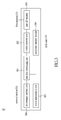
- the cable routing apparatus shown in Fig. 5 includes data processing unit 501 for processing internal signals among the circuits, especially the digital packets among the networks.
- the data processing unit 501 is electrically connected with an input/output interface unit 502 of a mobile network transceiver 52 such as the aforementioned wireless transceiver capable of network expansion. The apparatus is therefore capable of processing the signals over mobile communication network.
- the data processing unit 501 is also electrically connected with the network modules for processing various network protocols in the cable routing apparatus.
- the network modules are such as a LAN module 503, a wireless LAN module 504, a first network unit 505, a second network unit 506, and/or a third network unit 507.
- the cable routing apparatus may be installed with one or more network modules as described above.
- the cable routing apparatus is equipped with one or more networking measures.
- the first network unit 505 is used to bridge a digital subscriber line (DSL) 55 such as the general household ADSL.
- DSL digital subscriber line
- a DSL modem (not shown in this diagram) is required to establish the digital subscriber line 55.
- the cable routing apparatus has a second network unit 506 to establish a cable data line 56 by a cable modem.
- the cable routing apparatus is therefore allowed to bridge the cable data line 56, which provides an option for the user to select one of the network services.
- the cable routing apparatus may be disposed with a third network unit 507 in one further embodiment of the present invention.
- the network unit 507 renders establishment of an optical network line (PON) 57 which is also an option for the user to select.
- PON optical network line
- the cable routing apparatus is able to provide several options for the user to select one or more network services.
- the cable routing apparatus allows the user to link a local area network, or automatically switch to one of the supported network services.
- This cable routing apparatus particularly extends its network coverage through a mobile network transceiver 52 to a mobile communication network.
- the above mentioned network services are exemplarily described but not limited in the present invention.
- the cable routing apparatus has a LAN module 503 to serve the computer devices within a wired local area network 5 to link other networks.
- the cable routing apparatus is disposed with one or more LAN ports provided for the computer devices to link with this cable routing apparatus via cables, and further get on the mobile communication network through the expanding functions made by mobile network transceiver 52.
- the cable routing apparatus also has a wireless LAN module 504 in compliance with a general wireless local area network 54 by a specific communication protocol such as WiFiTM.
- the apparatus therefore provides the computer device within the LAN to link with this apparatus over a wireless connection.
- the LAN module 503, wireless LAN module 504, first network unit 505, second network unit 506, third network unit 507, and the mobile network transceiver 52 are separately process (encoding/decoding) the packets made by the various network types.
- the data processing unit 501 performs routing process according to the source and destination information extracted from the packets.
- the cable routing apparatus is able to extend its network coverage to the mobile communication network through its expanding module.
- the data processing unit 501 and the related firmware may perform a load balance over the various types of networks. That means a time-sharing technology is incorporated to the routing process allowing the packets routed to the different networks by the different network modules.
- the firmware may perform bandwidth integration over the various networks.
- the expandable routing system is formed in combination of the cable routing apparatus and the wireless transceiver.
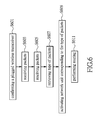
- Fig. 6 shows a flow chart illustrating the steps of packet routing.
- the cable routing apparatus is also expandable through combined with the expanding device, e.g. connected with the wireless transceiver via the contacts or/and interfaces.
- the network coverage of the cable routing apparatus is therefore extended to the mobile communication network.
- the cable routing apparatus confirms that a wireless transceiver is connected. For example, the cable routing apparatus may determine whether or not the wireless transceiver is connected by detecting the electrical features via the contacts.
- the apparatus next performs routing, such as step S603.
- the apparatus resolves the received network packets by its processing circuit, such as step S605.
- the type, source and destination of the packets may be recognized according to header information, such as step S607.
- a network unit corresponding to the detected type of packets is activated (step S609). Therefore, the corresponding network module performs the related decoding/encoding process.
- the apparatus successfully performs routing.
- the aforementioned expandable routing system essentially combines the two standalone devices, including a cable routing apparatus capable of processing routing among the various types of networks, and a wireless transceiver for bridging a mobile communication network.
- the cable routing apparatus is designed for expandable since it has the expanding mechanics and circuits.
- the cable routing apparatus particularly disposes an antenna unit and contacts supporting the wireless transceiver.
- the wireless transceiver has a module for conducting the mobile communication networking and the subscriber identity device.
- the module is in compliance with the fourth generation mobile communication network such as LTE.
- the wireless transceiver is also a transceiver provided for the computer host to get one mobile communication network.
- the combination of the cable routing apparatus and the wireless transceiver allows the expandable routing system to be extended to the mobile communication network in addition to the general network service.
Landscapes
- Engineering & Computer Science (AREA)
- Computer Networks & Wireless Communication (AREA)
- Signal Processing (AREA)
- Mobile Radio Communication Systems (AREA)
Abstract
Description
- The present invention is generally related to an expandable routing system, a wireless transceiver, and a cable routing apparatus; more particularly to the expandable routing system and the apparatus that is used to bridge a wireless transceiver for extending network over a mobile communication network.
- A network router is such as a network device that is in charge of forwarding the packets according to information of source and destination addresses extracted from the packets. The routing process finds a next routing path determined, by a processor of apparatus, to forward the packets to the destination. The network router forwards the packets according to the packets-carried information such as the source address and destination address. The routing process may need multiple routers to perform sequential routing.
- A regular router may forward the packets generated within a network to another network. The common household network sharing machine is used to transform the data created by the home device to the network packets that are applicably forwarded to external network. A common ADSL (asymmetric digital subscriber line) modem, cable modem, or even an optical fiber network device is an intermediate device for processing the routing.
- A router has a proprietary function that is to process routing. In case of changing the network type, for example advanced to next generation of communication network, the router lacks of upgrading mechanism to deal with the change. Therefore, the router may be knocked out since it fails to handle the new generation networking.
- For the regular routing device being adapted to the future network backbone over the mobile communication, an expandable routing system in accordance with the present invention is herein disclosed. The expandable system includes a wireless transceiver and a cable routing apparatus. The system may be able to access another wireless communication network by plugging with an expandable unit. For example, the system may expand its coverage to the fourth-generation mobile communication network (4G) or other wireless network by the invention.
- According to one of the embodiments, the expandable routing system essentially includes a wireless transceiver and a cable routing apparatus. The wireless transceiver is equipped with a first antenna contact and a first data connecting port. The cable routing apparatus has a second antenna contact and a second data connecting port. The first antenna contact is electrically with the second antenna contact as well the first data connecting port is linked with the second data connecting port when the wireless transceiver is plugged to or wiredly connected with the cable routing apparatus.
- The cable routing apparatus has an antenna unit that is used to process the wireless signals for the wireless transceiver. The apparatus may have internal or external antenna. Since the second antenna contact contacts the first antenna contact, an RF module of the wireless transceiver is connected to the antenna inside the cable routing apparatus. The antenna of the routing apparatus processes wireless signals. The cable routing apparatus may further have one or more network ports bridged to a network.
- In one further embodiment, the cable routing apparatus may include one or more LAN ports, such as the wired network ports or the wireless ports. The ports further includes at least one WAN port, by which bridges a digital subscriber line (DSL), cable data line Cable) or an optical network line such as a passive optical network (PON).
- In one embodiment, the mentioned first data connecting port of the wireless transceiver and the second data connecting port of the cable routing apparatus may be the corresponding USB ports that are operatively coupled.
- In one further embodiment, the disclosed expandable routing system is essentially made of a wireless transceiver and a cable routing apparatus. The wireless transceiver has a mobile network module, a first input/output interface unit and an RF module. The cable routing apparatus has a network routing module, a second input/output interface unit and an antenna unit. Furthermore, one or more connecting ports may be disposed with the cable routing apparatus.
- The wireless transceiver may be plugged into the cable routing apparatus via the mentioned connecting ports. The connection made by a direct insertion, or through a cable. In particular, the first input/output interface unit of the wireless transceiver is used to electrically connect with the second input/output interface unit of the cable routing apparatus via a data link. Therefore, the RF module of the wireless transceiver is able to use the antenna unit of the cable routing apparatus to process signals via an antenna link.
- The mentioned antenna may be an external device connected with the cable routing apparatus, or an internal component thereof. The antenna is an element used to receive or transmit wireless signals through the wireless transceiver. The mentioned data link is preferably a USB.
-
-
Fig. 1 shows a schematic diagram of the apparatus of the expandable routing system in accordance with one embodiment of the present invention; -
Fig. 2 shows a schematic diagram of the apparatus in the routing system according to one further embodiment of the present invention; -
Fig. 3 shows a circuit block diagram depicting the wireless transceiver according to one embodiment of the present invention; -
Fig. 4 shows a circuit diagram depicting the cable routing apparatus according to one embodiment of the present invention; -
Fig. 5 shows an embodiment describing the expandable routing system compatible to various types of networks; -
Fig. 6 shows a flow chart illustrating the steps of determining data routing routes by the expandable routing system. - The present invention now will be described more fully hereinafter with reference to the accompanying drawings, in which preferred embodiments of the invention are shown. This invention may, however, be embodied in many different forms and should not be construed as limited to the embodiments set forth herein; rather, these embodiments are provided so that this disclosure will be thorough and complete, and will fully convey the scope of the invention to those skilled in the art.
- Disclosure is related to an expandable routing system. The system combines two independent devices such as a wireless transceiver and a cable routing apparatus. Therefore, the expandable routing system is allowed to extend it network coverage to another wireless communication network, especially the mobile communication network such as fourth generation mobile communication network (4G). The 4G network generally means LTE (Long Term Evolution) or WiMAX. It is noted that the other types of mobile networks may not be excluded in this system.
- Reference is made to
Fig. 1 schematically depicting the expandable routing system in accordance with the embodiment of the present invention. The expandable routing system provides a scheme to extend the original network coverage. When the user has the cable routing apparatus, the cable routing apparatus operates as a router used to bridge the local area network and the wide area network. The apparatus may link the terminal devices via cables, e.g. RJ-45 cables, within the local area network. Further, the apparatus may link the terminal devices in LAN over wireless local area network, for example WiFi™. The cable routing apparatus serves the terminal devices to connect with external network. The asymmetric digital subscriber line (ADSL) modem, cable modem, or optical fiber network, e.g. passive optical network (PON), device may be used to render the network connection for the cable routing apparatus. - Two standalone devices are shown in
Fig. 1 . One of the devices is awireless transceiver 11 that is connected with acable routing apparatus 12 via the correspondingcontacts cable routing apparatus 12 may be exemplarily disposed with a socket to receive thewireless transceiver 11. However, the practical use may not be limited to any specific structure. - The
cable routing apparatus 12 may operates as a general router provided for the devices within the local area network to get on wide area network. Thecable routing apparatus 12 may have asecond antenna contact 120 that may be implemented to have one or more contacts. For example, the MIMO (multiple inputs and multiple outputs) antenna requires at least two contacts. One of the objectives of thesecond antenna contact 120 is to electrically connect with thefirst antenna contact 110 of thewireless transceiver 11. Thecontacts - In one embodiment of the present invention, the
cable routing apparatus 12 may have built-in or externally disposed antenna unit (not shown in this figure) provided for thewireless transceiver 11 to process wireless signals. The antenna unit may not render any function to thiscable routing apparatus 12, but served as the antenna for thewireless transceiver 11 while combined with thecable routing apparatus 12. - The
cable routing apparatus 12 has a seconddata connecting port 122 that is correspondingly connected with the firstdata connecting port 112 of thewireless transceiver 11. For example, USB embodies the transmission interface between the two ends of ports. Other types of connections may not be excluded in the present invention. - The
cable routing apparatus 12 is such as standalone router. As shown in the diagram, thecable routing apparatus 12 is electrically powered by an external power supply via apower connecting line 128. Theapparatus 12 may have its own power supply. Thecable routing apparatus 12 may be disposed with one or more network ports having at least oneWAN port 127 being used to link with ADSL modem, Cable modem, optical fiber network modem, or the like. ALAN port 126 may be provided to establish a LAN among the devices. Thecable routing apparatus 12 may have a circuit module provided to serve the devices within a wireless LAN. In which, a LAN module (not shown in this diagram) may be used to process RF (radio frequency) signals throughantenna 124. WiFi™ technology is the legacy scheme to establish the wireless local area network. The service made by theLAN port 126 over wired network or wireless network may be operated alternatively, or at the same time. - The
wireless transceiver 11 in the system may also be a standalone transceiver. A RF module (not shown in this diagram), processing circuit, and power management circuit may be included. Thefirst antenna contact 110 connected with the RF module may be the contact(s) to wire an external antenna. The external antenna may be connected to thetransceiver 11 via a cable. Therefore, thewireless transceiver 11 may serve a networking dongle for a computer host to get on mobile communication network while connected with the computer host via the firstdata connecting port 112. Meanwhile, the firstdata connecting port 112 is preferably, but not limited to, a USB port for data transmittal. - In particular, the
cable routing apparatus 12 may extend its network coverage to another network by an expanding device. For example, thecable routing apparatus 12 may be connected with thewireless transceiver 11 while the first andsecond antenna contacts data connecting ports wireless transceiver 11 may be wired to the antenna unit of thecable routing apparatus 12 via thefirst antenna contact 110 and thesecond antenna contact 120. The antenna unit serves as an antenna for thewireless transceiver 11. The association between thewireless transceiver 11 and thecable routing apparatus 12 may be made by plugging them together via an interface or by using cable to couple the two devices. By plugging or connecting the wireless transceiver, thecable routing apparatus 12 may extend its coverage to the mobile communication network through thewireless transceiver 11. -
Fig. 2 shows a schematic diagram of the devices in the expandable routing system. The figure depicts the relationship between thewireless transceiver 11 and thecable routing apparatus 12. - The
wireless transceiver 11 is disposed with theRF module 103. TheRF module 103 is an essential component of thewireless transceiver 11 when it conducts the 4G signals over the mobile communication network. The wireless transceiver is electrically connected with theantenna unit 106 associated with thecable routing apparatus 201 via theantenna link 201. Theantenna unit 106 is in charge of processing signals over the mobile communication network for thecable routing apparatus 12. Theantenna unit 106 may be a built-in component within theapparatus 12, or an external device. Theantenna unit 106 serves thewireless transceiver 11 while it is combined with thecable routing apparatus 12. - The
wireless transceiver 11 is such as a transceiver serving theapparatus 12 to bridge the mobile communication network. Thewireless transceiver 11 includes amobile network module 101 for rendering the wireless connection and processing the wireless signals. The first input/output interface unit 102 is such as USB that operates as a data transmission interface for thewireless transceiver 11. The first input/output interface unit 102 couples with the second input/output interface unit 105 of thecable routing apparatus 12 over thedata link 202. That means thecable routing apparatus 12 receives or transmits wireless signals through thewireless transceiver 11 via thedata link 202. - The
cable routing apparatus 12 is as a router that handles the signals over the LAN and WAN. The essential circuit performing packets routing is anetwork routing module 104. Thenetwork routing module 104 constitutes aLAN 22 by its one or more network ports, or wireless interface. The devices within theLAN 22 are allowed to accesswide area network 21 over wired interface, associated with one or more network ports, or wireless interface. - The
WAN 21 is accessible to the devices within theLAN 22 when thecable routing apparatus 12 establishes the connections by specifying an external modem. For example, the ADSL modem is provided for signaling with a telecommunication company over a telephony line. The cable modem helps establishing a cable data network. An optical fiber network device constitutes an optical fiber network connection. - In addition to
cable routing apparatus 12 performing routing process between LAN (22) and WAN (21), theapparatus 12 may extend its network coverage while combined with thewireless transceiver 11. The combination renders an expanding interface made by the second input/output interface unit 105 and theantenna unit 106. Therefore, thecable routing apparatus 12 may extend its networking to the mobile network connection through thewireless transceiver 11. In particular, thewireless transceiver 11 can be directly plugged to thecable routing apparatus 12. Further, thewireless transceiver 11 may also be wired to thecable routing apparatus 12 via a cable. - Reference is made to
Fig. 3 exemplarily showing the circuit blocks describing the wireless transceiver in the expandable routing system. - A
wireless transceiver 30 is shown. Thetransceiver 30 includes a firstdata processing unit 301 used to process the inner signals made by the circuits. Thewireless transceiver 30 is the device processing signals over mobile communication network. Thetransceiver 30 includes amobile network unit 302 used to process signals especially over the fourth generation mobile communication network, e.g. LTE. Themobile network unit 302 may activate the network service by initiating a subscriber identity module (SIM) 304. ASIM card 33 may be required to activate the mobile network service with the telecommunication company. A subscriber identity may be firstly verified by the telecommunication company or Internet service provider (ISP). Thewireless transceiver 30 processes the wireless signals over mobile communication network through itsfirst RF module 303, andfirst antenna 31. - The
wireless transceiver 30 is disposed with a first input/output interface unit 306 used to be a data transmission interface. Thewireless transceiver 30 may be standalone serving anexternal device 32 via this first input/output interface unit 306. Theexternal device 32 is such as a computer system which may bridge the mobile communication network through thiswireless transceiver 30. The first input/output interface unit 306 is such as a USB which is to be the data transmission interface with the cable routing apparatus. - While the
wireless transceiver 30 operates as a standalone device, an externalfirst antenna 31 may be associated with thetransceiver 30 for processing the signals over mobile communication network. Thewireless transceiver 30 may serve as an expanding component while thewireless transceiver 30 is combined with the cable routing apparatus. The mentionedfirst antenna 31 is therefore to be a built-in or externally disposed device for the cable routing apparatus. - The
wireless transceiver 30 has apower management unit 305 that is used to manage power supplied by the external power supply, or alternatively supplied by a built-in battery set. - A
cable routing apparatus 40 shown inFig. 4 is the other major device of the system in accordance with the present invention.Fig. 4 shows the circuit blocks describing the main circuits within thecable routing apparatus 40. A seconddata processing unit 401 is included for processing the signals created in theapparatus 40. Theapparatus 40 further includes the circuit units electrically connected with the seconddata processing unit 401. - The
cable routing apparatus 40 is such as a standalone router. Theapparatus 40 may include various network interfaces such as afirst network unit 405 and asecond network unit 406 coupled to thedata processing unit 401. Thenetwork units external modems - According to one of the embodiments, the
cable routing apparatus 40 may be disposed with two set of antennas at the same time. As shown in the figure, afirst antenna unit 402 and asecond antenna unit 411 are exemplarily provided. Thefirst antenna unit 402 is provided for use of the wireless transceiver. The antenna is useful for the external wireless transceiver but no effect to its associatedcable routing apparatus 40. The shownexternal device 41 is such as the wireless transceiver which is connected with thecable routing apparatus 40 through a second input/output interface unit 403 and thefirst antenna unit 402. - The
cable routing apparatus 40 establishes a wireless local area network by a WiFi™ network module. Awireless network unit 409 is used to process the wireless network signals. Thewireless network unit 409 may have both asecond RF module 410 and asecond antenna unit 411, and by which establish a wirelesslocal area network 45. - Further, the
cable routing apparatus 40 may handle the LAN signals by itsLAN unit 407, and establish aLAN 44 via a physical network interface unit (PHY) 408. - According to the exemplary embodiment of the present invention, the aforementioned
first network unit 405,second network unit 406,wireless network unit 409, andLAN unit 407 may be optional to the user to select one of the services. The installation of the various network units allows the expandable routing system of the present invention to extend its network coverage to the LAN or/and WAN through thiscable routing apparatus 40. Thecable routing apparatus 40 serves as a routing system for bridging mobile communication network while combined with the wireless transceiver. The standalonecable routing apparatus 40 is disposed with apower management unit 404 which is used to manage the power allocation. - According to the embodiment of the present invention, the expandable routing system may be compatible to the various types of network or operate for heterogeneous networks simultaneously. The related description is referred to the schematic diagram in
Fig. 5 . - The cable routing apparatus shown in
Fig. 5 includesdata processing unit 501 for processing internal signals among the circuits, especially the digital packets among the networks. Thedata processing unit 501 is electrically connected with an input/output interface unit 502 of amobile network transceiver 52 such as the aforementioned wireless transceiver capable of network expansion. The apparatus is therefore capable of processing the signals over mobile communication network. Thedata processing unit 501 is also electrically connected with the network modules for processing various network protocols in the cable routing apparatus. The network modules are such as aLAN module 503, awireless LAN module 504, afirst network unit 505, asecond network unit 506, and/or athird network unit 507. In practical, the cable routing apparatus may be installed with one or more network modules as described above. - According to one of the embodiments, the cable routing apparatus is equipped with one or more networking measures. For example, the
first network unit 505 is used to bridge a digital subscriber line (DSL) 55 such as the general household ADSL. In ADSL network, a DSL modem (not shown in this diagram) is required to establish thedigital subscriber line 55. - The cable routing apparatus has a
second network unit 506 to establish acable data line 56 by a cable modem. The cable routing apparatus is therefore allowed to bridge thecable data line 56, which provides an option for the user to select one of the network services. - The cable routing apparatus may be disposed with a
third network unit 507 in one further embodiment of the present invention. Thenetwork unit 507 renders establishment of an optical network line (PON) 57 which is also an option for the user to select. - The cable routing apparatus is able to provide several options for the user to select one or more network services. For example, the cable routing apparatus allows the user to link a local area network, or automatically switch to one of the supported network services. This cable routing apparatus particularly extends its network coverage through a
mobile network transceiver 52 to a mobile communication network. The above mentioned network services are exemplarily described but not limited in the present invention. - The cable routing apparatus has a
LAN module 503 to serve the computer devices within a wired local area network 5 to link other networks. The cable routing apparatus is disposed with one or more LAN ports provided for the computer devices to link with this cable routing apparatus via cables, and further get on the mobile communication network through the expanding functions made bymobile network transceiver 52. - The cable routing apparatus also has a
wireless LAN module 504 in compliance with a general wirelesslocal area network 54 by a specific communication protocol such as WiFi™. The apparatus therefore provides the computer device within the LAN to link with this apparatus over a wireless connection. - The
LAN module 503,wireless LAN module 504,first network unit 505,second network unit 506,third network unit 507, and themobile network transceiver 52 are separately process (encoding/decoding) the packets made by the various network types. Thedata processing unit 501 performs routing process according to the source and destination information extracted from the packets. - In particular, the cable routing apparatus is able to extend its network coverage to the mobile communication network through its expanding module. When the cable routing apparatus simultaneously performs routing process over two or more types of networks, the
data processing unit 501 and the related firmware may perform a load balance over the various types of networks. That means a time-sharing technology is incorporated to the routing process allowing the packets routed to the different networks by the different network modules. On the other hand, the firmware may perform bandwidth integration over the various networks. - The expandable routing system is formed in combination of the cable routing apparatus and the wireless transceiver.
Fig. 6 shows a flow chart illustrating the steps of packet routing. - In addition to the conventional network types supported by the cable routing apparatus, the cable routing apparatus is also expandable through combined with the expanding device, e.g. connected with the wireless transceiver via the contacts or/and interfaces. The network coverage of the cable routing apparatus is therefore extended to the mobile communication network.
- In the beginning step S601, the cable routing apparatus confirms that a wireless transceiver is connected. For example, the cable routing apparatus may determine whether or not the wireless transceiver is connected by detecting the electrical features via the contacts.
- The apparatus next performs routing, such as step S603. The apparatus then resolves the received network packets by its processing circuit, such as step S605. The type, source and destination of the packets may be recognized according to header information, such as step S607. A network unit corresponding to the detected type of packets is activated (step S609). Therefore, the corresponding network module performs the related decoding/encoding process. In step S611, the apparatus successfully performs routing.
- Thus, the aforementioned expandable routing system essentially combines the two standalone devices, including a cable routing apparatus capable of processing routing among the various types of networks, and a wireless transceiver for bridging a mobile communication network. The cable routing apparatus is designed for expandable since it has the expanding mechanics and circuits. The cable routing apparatus particularly disposes an antenna unit and contacts supporting the wireless transceiver. The wireless transceiver has a module for conducting the mobile communication networking and the subscriber identity device. For example, the module is in compliance with the fourth generation mobile communication network such as LTE. The wireless transceiver is also a transceiver provided for the computer host to get one mobile communication network. The combination of the cable routing apparatus and the wireless transceiver allows the expandable routing system to be extended to the mobile communication network in addition to the general network service.
- It is intended that the specification and depicted embodiment be considered exemplary only, with a true scope of the invention being determined by the broad meaning of the following claims.
Claims (15)
- An expandable routing system, comprising:a wireless transceiver (11), disposed with a first antenna contact (110), a first data connecting port (112), and an RF module (103) electrically connected with the first antenna contact (110); anda cable routing apparatus (12), disposed with a second antenna contact (120) and a second data connecting port (122), and further one or more network ports for bridging a network; with an internal or external antenna unit (106) provided for the wireless transceiver (11) to process wireless signaling;wherein, since the cable routing apparatus (12) and the wireless transceiver (11) are combined, the first antenna contact (110) is electrically connected with the second antenna contact (120), the first data connecting port (112) is electrically connected with the second data connecting port (122); the antenna unit (106) is then electrically connected with the RF module (103) of the wireless transceiver (11) for the wireless transceiver (11) to process wireless signaling.
- The system according to claim 1, wherein the network port of the cable routing apparatus (12) for bridging the network includes one or more LAN ports (126); wherein the LAN ports (126) are wired or wireless network ports, or simultaneously with both wired and wireless network ports.
- The system according to claim 2, wherein the cable routing apparatus (12) includes WAN port (127) which is used to bridge a digital subscriber line (55), a cable data line (56) or an optical network line (57).
- The system according to claim 1, wherein the wireless transceiver (11) is provided for bridging a mobile communication network; the cable routing apparatus (12) has a built-in antenna or externally connects with the antenna unit (106) provided for the wireless transceiver (11) to process signals over the mobile communication network.
- The system according to claim 1, wherein the first data connecting port (112) of the wireless transceiver (11) is correspondingly connected with the second data connecting port (122) of the cable routing apparatus (12) over USB.
- The system according to claim 5, wherein, when the wireless transceiver (11) is connected with the cable routing apparatus (12), the first antenna contact (110) and the first data connect port (112) of the wireless transceiver (11) are correspondingly plugged to the second antenna contact (120) and the second data connecting port (122) of the cable routing apparatus (12).
- The system according to claim 5, wherein, when the wireless transceiver (11) is combined with the cable routing apparatus (12), the first antenna contact (110) and the first data connecting port (112) of the wireless transceiver (11) are correspondingly connected with the second antenna contact (120) and the second data connecting port (122) of the cable routing apparatus (12) over at least two cables.
- An expandable routing system, comprising:a wireless transceiver (11), comprising a mobile network module, a first input/output interface unit (102) and an RF module (103); anda cable routing apparatus (12), comprising a network routing module (104), a second input/output interface unit (105) and a built-in or external antenna unit (106), and further one or more network ports bridged with a network;wherein, when the wireless transceiver (11) is combined with the cable routing apparatus (12), the first input/output interface unit (102) of the wireless transceiver (11) and the second input/output interface unit (105) of the cable routing apparatus (12) are connected via a data link; the RF module (103) of the wireless transceiver (11) is electrically connected with the antenna unit (106) associated with the cable routing apparatus (12) via an antenna link.
- The system according to claim 8, wherein the cable routing apparatus (12) includes one or more LAN port (126) bridged with the network; the one or more LAN ports (126) are wired or wireless network ports, or simultaneously both wired and wireless network ports.
- The system according to claim 9, wherein the cable routing apparatus includes a WAN port (127) bridged with the network; the WAN port (127) is provided for the system to bridge a digital subscriber line (55), a cable data line (56) or an optical network line (57).
- The system according to claim 8, wherein the wireless transceiver (11) is used to bridge a mobile communication network, the antenna unit (106) built in or externally disposed with the cable routing apparatus (12) is provided for the wireless transceiver (11) to process signals over the mobile communication network.
- The system according to claim 8, wherein the contacts of the wireless transceiver (11) are plugged with the contacts of the cable routing apparatus (12) via the data link and the antenna link.
- The system according to claim 8, wherein the contacts of the wireless transceiver (11) are connected with the contacts of the cable routing apparatus (12) through at least two cables.
- A wireless transceiver of the expandable routing system of claim 1 or 8 is provided for the expandable routing system to bridge a mobile communication network.
- A cable routing apparatus of the expandable routing system of claim 1 or 8 is provided for the expandable routing system to bridge a local area network or a wide area network.
Applications Claiming Priority (1)
| Application Number | Priority Date | Filing Date | Title |
|---|---|---|---|
| TW102215747U TWM468102U (en) | 2013-08-22 | 2013-08-22 | Expandable routing system, wireless transceiver, and wired routing apparatus |
Publications (1)
| Publication Number | Publication Date |
|---|---|
| EP2882257A1 true EP2882257A1 (en) | 2015-06-10 |
Family
ID=49944394
Family Applications (1)
| Application Number | Title | Priority Date | Filing Date |
|---|---|---|---|
| EP13198005.4A Withdrawn EP2882257A1 (en) | 2013-08-22 | 2013-12-18 | Expandable routing system (LTE + DSL) |
Country Status (3)
| Country | Link |
|---|---|
| EP (1) | EP2882257A1 (en) |
| DE (1) | DE202013104880U1 (en) |
| TW (1) | TWM468102U (en) |
Families Citing this family (2)
| Publication number | Priority date | Publication date | Assignee | Title |
|---|---|---|---|---|
| EP3090603A1 (en) * | 2013-12-31 | 2016-11-09 | The Antenna Company International N.V. | Lte/wifi wireless router |
| TWI650651B (en) * | 2017-12-28 | 2019-02-11 | 亞旭電腦股份有限公司 | Assembleable wireless networking device and integrated function system |
Citations (2)
| Publication number | Priority date | Publication date | Assignee | Title |
|---|---|---|---|---|
| KR20020055274A (en) * | 2000-12-28 | 2002-07-08 | 구자홍 | Managed switch for performing the function of broadband cable/dsl router |
| FR2929065A1 (en) * | 2008-03-18 | 2009-09-25 | Stephane Ruben | DEVICE FORMING GATEWAY BETWEEN AN INTERLOCUTOR PRESENT ON THE INTERNET NETWORK THROUGH P2P VOIP TECHNOLOGY SOFTWARE AND AT LEAST ONE MOBILE TELEPHONE SUBSCRIBER. |
-
2013
- 2013-08-22 TW TW102215747U patent/TWM468102U/en not_active IP Right Cessation
- 2013-10-31 DE DE201320104880 patent/DE202013104880U1/en not_active Expired - Lifetime
- 2013-12-18 EP EP13198005.4A patent/EP2882257A1/en not_active Withdrawn
Patent Citations (2)
| Publication number | Priority date | Publication date | Assignee | Title |
|---|---|---|---|---|
| KR20020055274A (en) * | 2000-12-28 | 2002-07-08 | 구자홍 | Managed switch for performing the function of broadband cable/dsl router |
| FR2929065A1 (en) * | 2008-03-18 | 2009-09-25 | Stephane Ruben | DEVICE FORMING GATEWAY BETWEEN AN INTERLOCUTOR PRESENT ON THE INTERNET NETWORK THROUGH P2P VOIP TECHNOLOGY SOFTWARE AND AT LEAST ONE MOBILE TELEPHONE SUBSCRIBER. |
Non-Patent Citations (4)
| Title |
|---|
| ANONYMOUS: "Streit um Hybrid-Router: Viprinet erwirkt Einstweilige Verfügungen gegen Telekom | heise online", 17 November 2014 (2014-11-17), XP055186868, Retrieved from the Internet <URL:http://www.heise.de/newsticker/meldung/Streit-um-Hybrid-Router-Viprinet-erwirkt-Einstweilige-Verfuegungen-gegen-Telekom-2466887.html> [retrieved on 20150429] * |
| DANIEL BEHRENS: "Die Profi-Lösung: Doppeltes DSL-Tempo zum stolzen Preis - Mehr Tempo - DSL & VoIP - PC-WELT", 6 July 2012 (2012-07-06), pages 1 - 3, XP055187122, Retrieved from the Internet <URL:http://www.pcwelt.de/ratgeber/Die-Profi-Loesung-Doppeltes-DSL-Tempo-zum-stolzen-Preis-Mehr-Tempo-5008.html> [retrieved on 20150430] * |
| DANIEL BEHRENS: "Mit zwei DSL-Leitungen gleichzeitig surfen - Mehr Tempo - DSL & VoIP - PC-WELT", 6 July 2012 (2012-07-06), pages 1 - 5, XP055187131, Retrieved from the Internet <URL:http://www.pcwelt.de/ratgeber/Mehr-Tempo-Mit-zwei-DSL-Leitungen-gleichzeitig-surfen-5000.html> [retrieved on 20150430] * |
| DANIEL BEHRENS: "Zwei UMTS-Sticks bündeln - Mehr Tempo - DSL & VoIP - PC-WELT", 6 July 2012 (2012-07-06), pages 1 - 5, XP055187129, Retrieved from the Internet <URL:http://www.pcwelt.de/ratgeber/Mehr-Tempo-durch-zwei-UMTS-Sticks-Mehr-Tempo-5006.html> [retrieved on 20150430] * |
Also Published As
| Publication number | Publication date |
|---|---|
| DE202013104880U1 (en) | 2013-12-17 |
| TWM468102U (en) | 2013-12-11 |
Similar Documents
| Publication | Publication Date | Title |
|---|---|---|
| US10797939B2 (en) | WAN control failover broker for vHGW | |
| US9008723B2 (en) | Wireless adapter | |
| US20110280175A1 (en) | Wireless relay device | |
| TWI477111B (en) | Outdoor wireless modem and method for signal procesisng thereof | |
| TW200803301A (en) | Automatic selection of a home agent | |
| EP2099180A1 (en) | Switching device and method for Layer-2 forwarding of OAM frames with multicast Layer-3 addresses | |
| JP5049069B2 (en) | Wireless communication terminal device and communication network program | |
| US10187916B2 (en) | Wireless adapter | |
| EP2882257A1 (en) | Expandable routing system (LTE + DSL) | |
| EP1817892B1 (en) | Method and system for opening a network link | |
| CN107786441B (en) | Communication method, OpenFlow switch and communication system | |
| CN203435014U (en) | An expandable route system, a wireless transmitting and receiving device, and a wired route device | |
| TWI511496B (en) | System of wireless communication, and method of management | |
| EP3079327A1 (en) | Information transmission method, device and system | |
| US9877348B2 (en) | Method and apparatus for establishing a backhaul link | |
| KR20170001654A (en) | Method for network address translation by using a software defined networking switch | |
| CN102201991B (en) | Data transmission method based on integral end-to-end multi-path transmission | |
| CN113285780B (en) | Method, device and system for configuring transmission pipeline | |
| JP5522374B2 (en) | COMMUNICATION MANAGEMENT CONTROL METHOD, COMMUNICATION MANAGEMENT CONTROL DEVICE, AND COMMUNICATION MANAGEMENT CONTROL PROGRAM | |
| EP3588866A1 (en) | Method and apparatus for configuring a routing table | |
| CN116599786A (en) | Communication method, device and storage medium | |
| JP2024033687A (en) | Relay device, program, and communication method | |
| KR20080051989A (en) | Power line communication apparatus comprising function of access point and network system comprising the apparatus | |
| KR20060135187A (en) | Home gateway using cable modem | |
| JP2010016624A (en) | Radio communication system, radio base station and packet transfer device |
Legal Events
| Date | Code | Title | Description |
|---|---|---|---|
| PUAI | Public reference made under article 153(3) epc to a published international application that has entered the european phase |
Free format text: ORIGINAL CODE: 0009012 |
|
| 17P | Request for examination filed |
Effective date: 20131218 |
|
| AK | Designated contracting states |
Kind code of ref document: A1 Designated state(s): AL AT BE BG CH CY CZ DE DK EE ES FI FR GB GR HR HU IE IS IT LI LT LU LV MC MK MT NL NO PL PT RO RS SE SI SK SM TR |
|
| AX | Request for extension of the european patent |
Extension state: BA ME |
|
| R17P | Request for examination filed (corrected) |
Effective date: 20150909 |
|
| RBV | Designated contracting states (corrected) |
Designated state(s): AL AT BE BG CH CY CZ DE DK EE ES FI FR GB GR HR HU IE IS IT LI LT LU LV MC MK MT NL NO PL PT RO RS SE SI SK SM TR |
|
| 17Q | First examination report despatched |
Effective date: 20170222 |
|
| GRAP | Despatch of communication of intention to grant a patent |
Free format text: ORIGINAL CODE: EPIDOSNIGR1 |
|
| INTG | Intention to grant announced |
Effective date: 20171025 |
|
| STAA | Information on the status of an ep patent application or granted ep patent |
Free format text: STATUS: THE APPLICATION IS DEEMED TO BE WITHDRAWN |
|
| 18D | Application deemed to be withdrawn |
Effective date: 20180306 |