EP2882034A1 - A radio-frequency or microwave resonator, a filter, and a method of filtering - Google Patents
A radio-frequency or microwave resonator, a filter, and a method of filtering Download PDFInfo
- Publication number
- EP2882034A1 EP2882034A1 EP13290304.8A EP13290304A EP2882034A1 EP 2882034 A1 EP2882034 A1 EP 2882034A1 EP 13290304 A EP13290304 A EP 13290304A EP 2882034 A1 EP2882034 A1 EP 2882034A1
- Authority
- EP
- European Patent Office
- Prior art keywords
- frequency
- radio
- microwave resonator
- resonator according
- core
- Prior art date
- Legal status (The legal status is an assumption and is not a legal conclusion. Google has not performed a legal analysis and makes no representation as to the accuracy of the status listed.)
- Withdrawn
Links
- 238000001914 filtration Methods 0.000 title claims description 4
- 238000000034 method Methods 0.000 title claims 2
- 239000000919 ceramic Substances 0.000 claims abstract description 34
- 230000005294 ferromagnetic effect Effects 0.000 claims abstract description 12
- 230000005291 magnetic effect Effects 0.000 claims abstract description 7
- 239000002184 metal Substances 0.000 claims description 9
- 230000035699 permeability Effects 0.000 claims description 8
- 229910000859 α-Fe Inorganic materials 0.000 description 11
- 230000005684 electric field Effects 0.000 description 10
- 239000000463 material Substances 0.000 description 9
- 229910010293 ceramic material Inorganic materials 0.000 description 6
- 238000009826 distribution Methods 0.000 description 6
- 238000010586 diagram Methods 0.000 description 4
- 239000003302 ferromagnetic material Substances 0.000 description 4
- 239000000523 sample Substances 0.000 description 4
- 238000003780 insertion Methods 0.000 description 3
- 230000037431 insertion Effects 0.000 description 3
- 230000008878 coupling Effects 0.000 description 2
- 238000010168 coupling process Methods 0.000 description 2
- 238000005859 coupling reaction Methods 0.000 description 2
- 239000003989 dielectric material Substances 0.000 description 2
- 238000005549 size reduction Methods 0.000 description 2
- 230000001413 cellular effect Effects 0.000 description 1
- 239000004020 conductor Substances 0.000 description 1
- 230000001419 dependent effect Effects 0.000 description 1
- 239000002223 garnet Substances 0.000 description 1
- 238000001465 metallisation Methods 0.000 description 1
- 239000000843 powder Substances 0.000 description 1
- 230000009467 reduction Effects 0.000 description 1
- 238000000926 separation method Methods 0.000 description 1
- 230000008646 thermal stress Effects 0.000 description 1
Images

Classifications
-
- H—ELECTRICITY
- H01—ELECTRIC ELEMENTS
- H01P—WAVEGUIDES; RESONATORS, LINES, OR OTHER DEVICES OF THE WAVEGUIDE TYPE
- H01P7/00—Resonators of the waveguide type
- H01P7/10—Dielectric resonators
-
- H—ELECTRICITY
- H01—ELECTRIC ELEMENTS
- H01P—WAVEGUIDES; RESONATORS, LINES, OR OTHER DEVICES OF THE WAVEGUIDE TYPE
- H01P1/00—Auxiliary devices
- H01P1/20—Frequency-selective devices, e.g. filters
- H01P1/207—Hollow waveguide filters
- H01P1/208—Cascaded cavities; Cascaded resonators inside a hollow waveguide structure
- H01P1/2084—Cascaded cavities; Cascaded resonators inside a hollow waveguide structure with dielectric resonators
-
- H—ELECTRICITY
- H01—ELECTRIC ELEMENTS
- H01P—WAVEGUIDES; RESONATORS, LINES, OR OTHER DEVICES OF THE WAVEGUIDE TYPE
- H01P1/00—Auxiliary devices
- H01P1/20—Frequency-selective devices, e.g. filters
- H01P1/215—Frequency-selective devices, e.g. filters using ferromagnetic material
Definitions
- the present invention relates to telecommunications, in particular to resonators for possible use in radio-frequency or microwave filtering.
- Filters are a key component of many radio-frequency (RF) and microwave-frequency systems such as for example cellular telecommunications base stations, point-to-point radio transceivers, and radar systems.
- RF radio-frequency
- microwave-frequency systems such as for example cellular telecommunications base stations, point-to-point radio transceivers, and radar systems.
- the type of filter chosen depends on the particular application, but there are certain common desirable characteristics for filters. For example, the insertion loss in the pass-band of the filter should be as low as possible, and the attenuation in the stop-band should be as high as possible.
- the frequency separation between the pass-band and stop-band needs to be very small, requiring a filter of high order. This frequency range is known as the guard-band.
- a challenging aspect of filter design is how to miniaturise the filter whilst maintaining electrical performance as compared to a similar but larger filter structure.
- Q factor quality factor
- Lumped elements In filters designed for low RF frequencies, lumped elements are used. Lumped elements have a Q factor in an approximate range of 60 to 100. On the other hand, cavity type resonators that can be used to construct filters have a Q factor which can be as high as several 1000s.
- ceramic monoblock filters are known with external metallisation. They offer significant size reduction but because of their relatively low Q factor of some 100s (typically 500 to 700) are unsuitable for many applications. Furthermore, their small size prevents their use in high power applications due to relatively high insertion losses and limited power handling capabilities.
- filters are those made up from ceramic resonators. These offer significant size reductions but are able to handle much higher powers than monoblock filters.
- the inventor realised that it was known to use high permeability materials in resonator design to reduce the size of resonator in proportion to the square root of real relative permittivity ( ⁇ r ) times real relative permeability ( ⁇ r ), denoted ⁇ r ⁇ ⁇ r .
- known ceramic filters are built from ceramic resonators in which the ceramic material is dielectric having a real relative permeability ( ⁇ r ) of about 1, but a real relative permittivity of several tens, usually in range of 30 - 80.
- An example of the present invention is a radio-frequency or microwave resonator comprising a dielectric ceramic core having a ferromagnetic ceramic covering, the covering in use providing a magnetic wall boundary to electromagnetic signals inside the resonator.
- the inventor found a way to produce a radio-frequency resonator having improved properties by including ferromagnetic ceramic covering. For example, a more even energy distribution within the core is provided.
- Preferred embodiments provide a magnetic wall boundary dielectric resonator.
- Preferred embodiments are a combination of both dielectric and ferromagnetic ceramic parts in an arrangement that allows the size of the dielectric part to be reduced, as compared to a comparable filter in which the ferromagnetic part is absent, for the same filtering frequency and without a significant increase in energy losses in the resonator.
- the dielectric ceramic part confine electromagnetic energy due to the high contrast between the dielectric ceramic part's permittivity and surrounding material(s), but also the ferromagnetic ceramic covering acts to aid that energy confinement as it introduces a high contrast between the permeability of the dielectric ceramic and the ferromagnetic ceramic covering.
- the ferromagnetic ceramic covering enhances the magnetic wall boundary at the surface of the dielectric ceramic bringing it closer to perfect magnetic boundary conditions.
- Preferred embodiments allow a significant reduction in resonator size, and hence filter size, due to introducing a material of high relative permeability in addition to a material of high relative permittivity.
- Preferred embodiments provide reduced size filters comprising reduced size resonators.
- Preferred embodiments allow miniaturisation of ceramic resonators that may be cavity resonators, for example at least partially filling cavities within a metallic outer casing.
- Preferred embodiments may be smaller sized, with better RF power handling and thermal properties than a known alternative.
- Preferred embodiments operate in the radio-frequency or microwave frequency bands.
- this known resonator 2 consists of a cylindrical core 4 of dielectric ceramic material fitting tightly within a metal casing 8.
- the shape of the core 4 can be considered a puck 6.
- the real relative permittivity of the core 4 is 38, the height is 12mm and the diameter is 25mm.
- the first (lowest radio-frequency) resonating mode is TM 010 .
- the inventors realised that an improved field distribution was possible.
- a resonator 12 consisting of a cylindrical core 14 of dielectric ceramic material, surrounded by a tightly fitting thin cylindrical ring 16 of ceramic ferromagnetic material, also known as ferrite.
- the ceramic material is Ceramic DR-45 from TCI Ceramics Inc
- the ferromagnetic material is garnet NG-1850 from TCI Ceramics Inc.
- This assembly of core 14 and ferrite ring 16 fits into a tightly-fitting metal casing 18.
- the core 14 and ferrite ring 16 can be considered together as a puck 20.
- the real relative permittivity of the core 14 is 38, the height is 12mm and the diameter is 25mm.
- the first (lowest radio-frequency) resonating mode is TM 010 .
- the ferrite ring 16 is made of ferrite material having a high relative magnetic permeability ( ⁇ r ) of 100. In this example the thickness of the ferrite 16 is 1 mm.
- ceramic ferromagnetic material possess an anisotropic real relative permittivity of up to 1000s, but are significantly more lossy, in other words have a significantly higher imaginary relative permittivity component, than dielectric ceramic materials, so their volumetric contribution to the resonator should be sufficient to be effective, but kept to a minimum.
- An example filter 22 is shown in Figures 7 to 9 , and includes two resonators 12 as described above in relation to Figures 4 to 6 .
- the filter 22 has a metal casing 24 within which is a cavity 26.
- the filter 22 is a two pole filter in that two resonators 12 are provided.
- the resonators 12 are coupled via an opening 28 known as an iris 28 between internal walls 30 in the cavity 26.
- the size of the opening 28 dictates the level of coupling between the two resonators 12.
- the resonators 12 are both cylindrical and of a dielectric material of high permittivity, and are each sleeved in the respective ferrite ring 16 so as to provide a respective puck 20.
- the top (not shown) and bottom (not shown) of the puck 20 contact the respective top (not shown) and bottom 32 of the cavity 26.
- the cavity 26 is otherwise substantially air-filled.
- the filter 22 includes a metallic end launch probe 34 near the first resonator 12' used for signal input.
- a similar metallic end probe 36 is provided near the second resonator 12" used for signal output.
- each resonator 12 consists of a high permittivity dielectric core 12 covered at its sides by a ferromagnetic ring 16.
- the diameter of the resonator dictates the resonant frequency of the resonator 12 and effectively the centre frequency of the filter 22.
- the above mentioned example resonator described with reference to Figure 4 to 6 is cylindrical, being in the shape of a puck 20.
- the resonator can be in the shape of a cylindrical puck or post, a puck or post of rectangular- or square- cross section, another regular shape, or any shape. Regular shapes are easier to machine.
- the ferrite material can be in the form of a sleeve that tightly fits the resonator or be a layer deposited on the dielectric ceramic material core.
- the resonator is within a metal casing.
- the metal casing may be a tight-fitting to the resonator or not, for example the resonator can be used within a cavity in a cavity filter, for example a comb-line filter in which the resonator is substantially surrounded by air or some other material, for example a dielectric powder.
- the present invention may be embodied in other specific forms without departing from its essential characteristics.
- other dielectric and ferromagnetic materials may be used. These materials are available from various suppliers including TCI Ceramics Inc, Murata and Kyocera.
- TCI Ceramics Inc, Murata and Kyocera are available from various suppliers including TCI Ceramics Inc, Murata and Kyocera.
- the described embodiments are to be considered in all respects only as illustrative and not restrictive. The scope of the invention is, therefore, indicated by the appended claims rather than by the foregoing description. All changes that come within the meaning and range of equivalency of the claims are to be embraced within their scope.
Landscapes
- Control Of Motors That Do Not Use Commutators (AREA)
Abstract
Description
- The present invention relates to telecommunications, in particular to resonators for possible use in radio-frequency or microwave filtering.
- Filters are a key component of many radio-frequency (RF) and microwave-frequency systems such as for example cellular telecommunications base stations, point-to-point radio transceivers, and radar systems. The type of filter chosen depends on the particular application, but there are certain common desirable characteristics for filters. For example, the insertion loss in the pass-band of the filter should be as low as possible, and the attenuation in the stop-band should be as high as possible. Furthermore, in some applications the frequency separation between the pass-band and stop-band needs to be very small, requiring a filter of high order. This frequency range is known as the guard-band.
- A challenging aspect of filter design is how to miniaturise the filter whilst maintaining electrical performance as compared to a similar but larger filter structure.
- One of the main parameters determining a filter's selectivity in terms of frequency, and insertion loss, is the so-called quality factor ("Q factor") of the elements that make up the filter. The Q factor is defined as the ratio of energy stored in the filter element to the time-averaged power loss.
- In filters designed for low RF frequencies, lumped elements are used. Lumped elements have a Q factor in an approximate range of 60 to 100. On the other hand, cavity type resonators that can be used to construct filters have a Q factor which can be as high as several 1000s.
- Although some miniaturisation of lumped element filters is possible, their low Q factors prohibit their use in highly demanding applications where high frequency rejection or selectivity is required. On the other hand, cavity resonators offer sufficiently high Q factors but their large sizes prevent their use in many applications.
- The problem of miniaturising filters is known to be particularly pressing in the field of small cell base stations, as it has been realised that the footprint of a small cell base stations should be minimal. Furthermore, a known trend in base stations is a shift from a single frequency band capability to a multiband capability whilst seeking to maintain the same physical footprint and avoid detriment to system performance.
- Several known solutions exist. For relatively low powers, ceramic monoblock filters are known with external metallisation. They offer significant size reduction but because of their relatively low Q factor of some 100s (typically 500 to 700) are unsuitable for many applications. Furthermore, their small size prevents their use in high power applications due to relatively high insertion losses and limited power handling capabilities.
- Another known type of filters are those made up from ceramic resonators. These offer significant size reductions but are able to handle much higher powers than monoblock filters.
- The inventor realised that it was known to use high permeability materials in resonator design to reduce the size of resonator in proportion to the square root of real relative permittivity (εr) times real relative permeability (µr), denoted

- The inventor also realised that known ceramic filters are built from ceramic resonators in which the ceramic material is dielectric having a real relative permeability (µr) of about 1, but a real relative permittivity of several tens, usually in range of 30 - 80.
- The reader is referred to the appended independent claims. Some preferred features are laid out in the dependent claims.
- An example of the present invention is a radio-frequency or microwave resonator comprising a dielectric ceramic core having a ferromagnetic ceramic covering, the covering in use providing a magnetic wall boundary to electromagnetic signals inside the resonator.
- The inventor found a way to produce a radio-frequency resonator having improved properties by including ferromagnetic ceramic covering. For example, a more even energy distribution within the core is provided.
- Preferred embodiments provide a magnetic wall boundary dielectric resonator.
- Preferred embodiments are a combination of both dielectric and ferromagnetic ceramic parts in an arrangement that allows the size of the dielectric part to be reduced, as compared to a comparable filter in which the ferromagnetic part is absent, for the same filtering frequency and without a significant increase in energy losses in the resonator.
- In preferred embodiments, not only does the dielectric ceramic part confine electromagnetic energy due to the high contrast between the dielectric ceramic part's permittivity and surrounding material(s), but also the ferromagnetic ceramic covering acts to aid that energy confinement as it introduces a high contrast between the permeability of the dielectric ceramic and the ferromagnetic ceramic covering.
- It can be considered that the ferromagnetic ceramic covering enhances the magnetic wall boundary at the surface of the dielectric ceramic bringing it closer to perfect magnetic boundary conditions.
- Preferred embodiments allow a significant reduction in resonator size, and hence filter size, due to introducing a material of high relative permeability in addition to a material of high relative permittivity.
- Preferred embodiments provide reduced size filters comprising reduced size resonators. Preferred embodiments allow miniaturisation of ceramic resonators that may be cavity resonators, for example at least partially filling cavities within a metallic outer casing.
- Preferred embodiments may be smaller sized, with better RF power handling and thermal properties than a known alternative.
- Preferred embodiments operate in the radio-frequency or microwave frequency bands.
- An embodiment of the present invention will now be described by way of example and with reference to the drawings, in which:
-
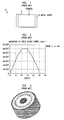
Figure 1 is a diagram illustrating a known cylindrical radio-frequency ceramic resonator within a metal casing (PRIOR ART), -
Figure 2 is a diagram illustrating the magnitude of the electric field across the diameter of the resonator shown inFigure 1 (PRIOR ART), -
Figure 3 is a perspective illustration of how magnitude of this electric field varies in the resonator shown inFigure 1 (PRIOR ART), -
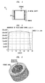
Figure 4 is a diagram illustrating a cylindrical radio-frequency ceramic resonator according to an embodiment of the present invention within a metal casing, and -
Figure 5 is a diagram illustrating the magnitude of the electric field across the diameter of the resonator shown inFigure 4 , -
Figure 6 is a perspective illustration of how the magnitude of this electric field varies in the resonator shown inFigure 4 , -
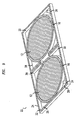
Figure 7 is a perspective view of a filter including resonators as shown inFigure 4 , -
Figure 8 is a cross-sectional view along the line A-A of the filter shown inFigure 7 , and -
Figure 9 is a perspective cross-sectional view of the filter shown inFigures 7 and 8 . - The inventors considered a known
ceramic resonator 2 as shown inFigure 1 . As shown inFigure 1 , this knownresonator 2 consists of acylindrical core 4 of dielectric ceramic material fitting tightly within ametal casing 8. The shape of thecore 4 can be considered apuck 6. In this example, the real relative permittivity of thecore 4 is 38, the height is 12mm and the diameter is 25mm. The first (lowest radio-frequency) resonating mode is TM010. - The inventors realised that an improved field distribution was possible.
- As shown in
Figure 4 , the inventors devised aresonator 12 consisting of acylindrical core 14 of dielectric ceramic material, surrounded by a tightly fitting thincylindrical ring 16 of ceramic ferromagnetic material, also known as ferrite. In this example the ceramic material is Ceramic DR-45 from TCI Ceramics Inc, and the ferromagnetic material is garnet NG-1850 from TCI Ceramics Inc. This assembly ofcore 14 andferrite ring 16 fits into a tightly-fitting metal casing 18. Thecore 14 andferrite ring 16 can be considered together as apuck 20. In this example, the real relative permittivity of thecore 14 is 38, the height is 12mm and the diameter is 25mm. The first (lowest radio-frequency) resonating mode is TM010. Theferrite ring 16 is made of ferrite material having a high relative magnetic permeability (µr) of 100. In this example the thickness of theferrite 16 is 1 mm. - The inventors realised that ceramic ferromagnetic material (ferrite materials) possess an anisotropic real relative permittivity of up to 1000s, but are significantly more lossy, in other words have a significantly higher imaginary relative permittivity component, than dielectric ceramic materials, so their volumetric contribution to the resonator should be sufficient to be effective, but kept to a minimum.
- Comparison of
Figure 5 withFigure 2 , andFigure 6 withFigure 3 , reveal that the electric field strength (E-Field) distributions are significantly different. More specifically, theresonator 2 ofFigure 1 (PRIOR ART) shows a highly concentrated field in the centre of thepuck 6 with the magnitude of the electric field steadily decaying towards the outer edge, which acts as an electric wall, where the field becomes zero. On the other hand, theresonator 12 ofFigure 4 which includes thepuck 20 having theceramic core 14 andferrite ring 16 shows a much more evenly distributed electric field through the volume of thepuck 20 with a clearly defined field inside theferrite ring 16 that rapidly decays as a function of distance towards the outer edge where the field becomes zero. - In the known example shown in
Figures 1 (PRIOR ART) to 3 (PRIOR ART), the energy distribution is less uniform, hence the effective electrical size of the resonator is smaller, and so the resonant frequency is higher (1.479 GHz in this example). - Conversely, in the example shown in
Figures 4 to 6 the energy distribution is much more uniform, hence the effective electrical size is larger, and so the resonant frequency is lower (0.311 GHz in this example). - In the example shown in
Figure 4 , as the field is distributed much more evenly, there is no region of relatively high electric field; in other words the electric field "hotspot", which occurs in the known resonator shown inFigure 1 (PRIOR ART), is avoided. This advantageously allows for higher power handling than in the known approach. - In the known approach, as ceramics are poor heat conductors, the thermal stresses induced by the electric field "hotspot" can result in catastrophic structural failure. Furthermore uneven heat distribution tends to degrade electrical performance as different areas of the resonator are more likely to be at different temperatures resulting in varying thermal expansions and variations in permittivity due to temperature variations. The example shown in
Figure 4 avoids these disadvantages. - An
example filter 22 is shown inFigures 7 to 9 , and includes tworesonators 12 as described above in relation toFigures 4 to 6 . - As shown in
Figure 7 to 9 , thefilter 22 has ametal casing 24 within which is acavity 26. Thefilter 22 is a two pole filter in that tworesonators 12 are provided. Theresonators 12 are coupled via anopening 28 known as aniris 28 betweeninternal walls 30 in thecavity 26. The size of theopening 28 dictates the level of coupling between the tworesonators 12. - The
resonators 12 are both cylindrical and of a dielectric material of high permittivity, and are each sleeved in therespective ferrite ring 16 so as to provide arespective puck 20. The top (not shown) and bottom (not shown) of thepuck 20 contact the respective top (not shown) and bottom 32 of thecavity 26. Thecavity 26 is otherwise substantially air-filled. - The
filter 22 includes a metallicend launch probe 34 near the first resonator 12' used for signal input. The distance between the probe and the resonator, and the length of the probe, dictate the amount of coupling and the loaded quality factor of the resonator. A similarmetallic end probe 36 is provided near thesecond resonator 12" used for signal output. - As mentioned above each
resonator 12 consists of a highpermittivity dielectric core 12 covered at its sides by aferromagnetic ring 16. The diameter of the resonator dictates the resonant frequency of theresonator 12 and effectively the centre frequency of thefilter 22. - The above mentioned example resonator described with reference to
Figure 4 to 6 is cylindrical, being in the shape of apuck 20. Other shapes are possible. For example, the resonator can be in the shape of a cylindrical puck or post, a puck or post of rectangular- or square- cross section, another regular shape, or any shape. Regular shapes are easier to machine. The ferrite material can be in the form of a sleeve that tightly fits the resonator or be a layer deposited on the dielectric ceramic material core. - In the example described with reference to
Figures 4 to 6 , the resonator is within a metal casing. The metal casing may be a tight-fitting to the resonator or not, for example the resonator can be used within a cavity in a cavity filter, for example a comb-line filter in which the resonator is substantially surrounded by air or some other material, for example a dielectric powder. - The present invention may be embodied in other specific forms without departing from its essential characteristics. For example, other dielectric and ferromagnetic materials may be used. These materials are available from various suppliers including TCI Ceramics Inc, Murata and Kyocera. The described embodiments are to be considered in all respects only as illustrative and not restrictive. The scope of the invention is, therefore, indicated by the appended claims rather than by the foregoing description. All changes that come within the meaning and range of equivalency of the claims are to be embraced within their scope.
Claims (15)
- A radio-frequency or microwave resonator, the resonator comprising a dielectric ceramic core having a ferromagnetic ceramic covering.
- A radio-frequency or microwave resonator according to claim 1, in which the covering in use provides a magnetic wall boundary to electromagnetic signals inside the resonator.
- A radio-frequency or microwave resonator according to claim 1 or claim 2, in which the covering has a relative permittivity lower than the relative permittivity of the core.
- A radio-frequency or microwave resonator according to any preceding claim, in which the core is of a simple shape having sides and the covering covers said sides.
- A radio-frequency or microwave resonator according to any preceding claim, in which the core is cylindrical and the covering is a tubular sleeve or ring.
- A radio-frequency or microwave resonator according to claim 5, in which the core is a puck or post.
- A radio-frequency or microwave resonator according to any preceding claim, in which the core is of rectangular cross-section and the covering is a sleeve of rectangular cross section.
- A radio-frequency or microwave resonator according to claim 7, in which the core is a puck, post or a cuboid.
- A radio-frequency or microwave resonator according to any preceding claim, in which the covering has a thickness thick enough to provide a high contrast in relative permeability with the core and thin enough to avoid large energy losses in the covering.
- A radio-frequency or microwave resonator according to any preceding claim, in which the ferromagnetic ceramic has a relative permittivity of about 1.
- A radio-frequency or microwave resonator according to any preceding claim, in which the ferromagnetic ceramic has a relative permeability in the order of tens to in the order of thousands.
- A radio-frequency or microwave resonator according to any preceding claim, in which the dielectric ceramic has a relative permittivity in the range 30 to 300.
- A radio-frequency or microwave radio-frequency resonator according to any preceding claim, further comprising a metal casing for electromagnetic shielding.
- A filter comprising at least one radio-frequency or microwave resonator according to any preceding claim and a metal housing within which each resonator resides.
- A method of filtering comprising passing an input signal through a filter comprising a radio-frequency or microwave resonator according to any of claims 1 to 13, so as to provide a filtered output signal.
Priority Applications (1)
| Application Number | Priority Date | Filing Date | Title |
|---|---|---|---|
| EP13290304.8A EP2882034A1 (en) | 2013-12-09 | 2013-12-09 | A radio-frequency or microwave resonator, a filter, and a method of filtering |
Applications Claiming Priority (1)
| Application Number | Priority Date | Filing Date | Title |
|---|---|---|---|
| EP13290304.8A EP2882034A1 (en) | 2013-12-09 | 2013-12-09 | A radio-frequency or microwave resonator, a filter, and a method of filtering |
Publications (1)
| Publication Number | Publication Date |
|---|---|
| EP2882034A1 true EP2882034A1 (en) | 2015-06-10 |
Family
ID=51298497
Family Applications (1)
| Application Number | Title | Priority Date | Filing Date |
|---|---|---|---|
| EP13290304.8A Withdrawn EP2882034A1 (en) | 2013-12-09 | 2013-12-09 | A radio-frequency or microwave resonator, a filter, and a method of filtering |
Country Status (1)
| Country | Link |
|---|---|
| EP (1) | EP2882034A1 (en) |
Cited By (1)
| Publication number | Priority date | Publication date | Assignee | Title |
|---|---|---|---|---|
| WO2023066038A1 (en) * | 2021-10-22 | 2023-04-27 | 华为技术有限公司 | Dielectric filter and communication device |
Citations (5)
| Publication number | Priority date | Publication date | Assignee | Title |
|---|---|---|---|---|
| US4122418A (en) * | 1975-05-10 | 1978-10-24 | Tsukasa Nagao | Composite resonator |
| FR2521786A2 (en) * | 1981-02-27 | 1983-08-19 | Thomson Csf | Pass band filter with dielectric resonators - uses ferrimagnetic elements subjected to external magnetic field to modify resonant frequency |
| US5469128A (en) * | 1993-09-17 | 1995-11-21 | Nissan Motor Co., Ltd. | Circuit elements for microwave and millimeter-wave bands and method of producing same |
| US20010045872A1 (en) * | 1999-01-10 | 2001-11-29 | Tdk Corporation | Non-reciprocal circuit element and millimeter-wave hybrid integrated circuit board with the non-reciprocal circuit element |
| GB2380069A (en) * | 2001-04-09 | 2003-03-26 | South Bank Univ Entpr Ltd | Dielectric resonator with ferroelectric tuner |
-
2013
- 2013-12-09 EP EP13290304.8A patent/EP2882034A1/en not_active Withdrawn
Patent Citations (5)
| Publication number | Priority date | Publication date | Assignee | Title |
|---|---|---|---|---|
| US4122418A (en) * | 1975-05-10 | 1978-10-24 | Tsukasa Nagao | Composite resonator |
| FR2521786A2 (en) * | 1981-02-27 | 1983-08-19 | Thomson Csf | Pass band filter with dielectric resonators - uses ferrimagnetic elements subjected to external magnetic field to modify resonant frequency |
| US5469128A (en) * | 1993-09-17 | 1995-11-21 | Nissan Motor Co., Ltd. | Circuit elements for microwave and millimeter-wave bands and method of producing same |
| US20010045872A1 (en) * | 1999-01-10 | 2001-11-29 | Tdk Corporation | Non-reciprocal circuit element and millimeter-wave hybrid integrated circuit board with the non-reciprocal circuit element |
| GB2380069A (en) * | 2001-04-09 | 2003-03-26 | South Bank Univ Entpr Ltd | Dielectric resonator with ferroelectric tuner |
Cited By (1)
| Publication number | Priority date | Publication date | Assignee | Title |
|---|---|---|---|---|
| WO2023066038A1 (en) * | 2021-10-22 | 2023-04-27 | 华为技术有限公司 | Dielectric filter and communication device |
Similar Documents
| Publication | Publication Date | Title |
|---|---|---|
| Zhang et al. | Compact substrate integrated waveguide (SIW) bandpass filter with complementary split-ring resonators (CSRRs) | |
| US10205214B2 (en) | Radio-frequency filter | |
| Chu et al. | Novel UWB bandpass filter using stub-loaded multiple-mode resonator | |
| KR101239209B1 (en) | Suspended dielectric combline cavity filter | |
| Shen et al. | Miniaturized dual-band substrate integrated waveguide filter with controllable bandwidths | |
| Lee et al. | K-band substrate-integrated waveguide resonator filter with suppressed higher-order mode | |
| US20020041221A1 (en) | Tunable bandpass filter | |
| Huang et al. | Compact ridged half-mode substrate integrated waveguide bandpass filter | |
| Lee et al. | K-band frequency tunable substrate-integrated-waveguide resonator filter with enhanced stopband attenuation | |
| EP2903084B1 (en) | A resonator assembly and filter | |
| Lee et al. | Post-loaded substrate-integrated waveguide bandpass filter with wide upper stopband and reduced electric field intensity | |
| CA2849854A1 (en) | Radiofrequency filter with dielectric element | |
| Kumar et al. | Design of improved quadruple-mode bandpass filter using cavity resonator for 5G mid-band applications | |
| EP2882034A1 (en) | A radio-frequency or microwave resonator, a filter, and a method of filtering | |
| US9343791B2 (en) | Frequency-tunable microwave-frequency wave filter with a dielectric resonator including at least one element that rotates | |
| KR101468409B1 (en) | Dual mode resonator including the disk with notch and filter using the same | |
| US20140266961A1 (en) | Mode Filter | |
| US9673500B2 (en) | Artificial dielectric resonator and artificial dielectric filter using the same | |
| EP3012901B1 (en) | A resonator, a radio frequency filter, and a method of filtering | |
| EP2804254A1 (en) | A radio frequency filter, a method of radio frequency filtering, and a method of constructing a filter | |
| Turgaliev et al. | Small-size dual-band filters on capacitively loaded cavities | |
| He et al. | A dual-band bandpass filter based on hybrid structure of substrate integrated waveguide and substrate integrated coaxial line | |
| Lee et al. | $ K $-Band Substrate-Integrated Waveguide Filter Using TM21 Mode With Enhanced Stopband Attenuation | |
| US9620836B2 (en) | Bandpass microwave filter tunable by a 90 degree rotation of a dielectric element between first and second positions | |
| Martínez et al. | Compact SIW filter with asymmetric frequency response for C-band wireless applications |
Legal Events
| Date | Code | Title | Description |
|---|---|---|---|
| PUAI | Public reference made under article 153(3) epc to a published international application that has entered the european phase |
Free format text: ORIGINAL CODE: 0009012 |
|
| 17P | Request for examination filed |
Effective date: 20131209 |
|
| AK | Designated contracting states |
Kind code of ref document: A1 Designated state(s): AL AT BE BG CH CY CZ DE DK EE ES FI FR GB GR HR HU IE IS IT LI LT LU LV MC MK MT NL NO PL PT RO RS SE SI SK SM TR |
|
| AX | Request for extension of the european patent |
Extension state: BA ME |
|
| R17P | Request for examination filed (corrected) |
Effective date: 20151210 |
|
| RBV | Designated contracting states (corrected) |
Designated state(s): AL AT BE BG CH CY CZ DE DK EE ES FI FR GB GR HR HU IE IS IT LI LT LU LV MC MK MT NL NO PL PT RO RS SE SI SK SM TR |
|
| RAP1 | Party data changed (applicant data changed or rights of an application transferred) |
Owner name: ALCATEL LUCENT |
|
| 17Q | First examination report despatched |
Effective date: 20180621 |
|
| STAA | Information on the status of an ep patent application or granted ep patent |
Free format text: STATUS: THE APPLICATION IS DEEMED TO BE WITHDRAWN |
|
| 18D | Application deemed to be withdrawn |
Effective date: 20200820 |